Embed Size (px)
Citation preview

Basics of Magnetic Resonance Imaging (MRI)
Shaoying HUANG, PhD
Singapore University of Technology and Design

• Medical imaging modalities
• History of MRI
• Working principles of MRI
OUTLINE

• X-ray radiography
• X-ray computed tomography (CT)
• Medical ultrasonography
• MRI
Medical Imaging Modalities
Create images of human body non-invasively
3

www.medicalradiation.com
X-ray radiography
- 2D images
- Radiation: X-ray is
absorbed by the subject
www.toshiba-medical.eu
X-ray
generator
Projected
plane
Subject
Medical Imaging Modalities
4
To use X-rays to view the internal structure of a
non-uniformly composed and opaque object

X-ray Computed Tomography (CT)
Medical Imaging Modalities
www.cedars-sinai.edu
- 3D images
- X-ray absorbed by the subject is 100 times of that by
using x-ray radiography
www.capitalhealth.org
5
To generate a 3D image of the internal structure of
an object from a large series of 2D radiographic
images taken around a single axis of rotation

Medical ultrasonography
Medical Imaging Modalities
- It displays
• 2D cross-section of the tissue
• Blood flow
• Motion of the tissue over time
• The location of blood
• The present of specific molecules
• The stiff ness of tissues
• Anatomy of 3D region
- Advantages
• Provide real-time images
• Portable
• Low cost
• No harmful radiation
- Limitations on field of view
• Difficult imaging structure behind bone
• The skill of operators matters
blog.healthtap.com
www.haam.us
www.upmc.com
6
Obstetric sonography
Ultrasound-based imaging technique used
for visualizing subcutaneous body
structures

Medical Imaging Modalities
billpstudios.blogspot.com
Magnetic Resonance Imaging (MRI)
- 3D images
- Low RF radiation
- Cost: 2 - 4 millions USD www.magnet.fsu.edu
7

MRI
Advantages:
• Good contrast
• Noninvasive
• No ionizing radiation
• Arbitrary scan planes
Different names of MRI
Magnetic resonance imaging (MRI)
Nuclear magnetic resonance imaging (NMRI)
Magnetic resonance tomography (MRT)
Abdomen Spine Heart / Coronary
http://mrsrl.stanford.edu/~brian/intromr/ 8

History of MRI
1952 Herman Carr
(Harvard University)
Produced 1D MRI image
1960 Vladislav Ivanov
(Soviet Union)
Filed a document for a magnetic resonance
imaging device (USSR State Committee for
Inventions and Discovery at Leningrad)
1970 Peter Mansfield
(University of
Nottingham)
Developed a mathematical technique that would
allow scans to take seconds rather than hours and
produce clearer images than Lauterbur had.
1971 Raymond Damadian
(State University of
New York)
Reported tumors and normal tissue can be
distinguished in vivo by NMR [Science]. This
method is not effective and not practical.
1972 Raymond Damadian Created the world’s first MRI machine & filed a
patent
1973 Paul Lauterbur (State
University of New
York)
Expended Carr’s technique & generated and
published the first nuclear magnetic resonance 2D
and 3D images (using gradients)
9

History of MRI
Raymond Damadian's apparatus and method for detecting cancer in tissue [1]
[1] www.fonar.com [2] "Scientist Claims Exclusion From Nobel Prize for MRI". Los Angeles Times. 2003-11-08. Retrieved 2013-02-13.
[3] "Does Dr. Raymond Damadian Deserve the Nobel Prize for Medicine?". The Armenian Reporter. 2003-11-08. Retrieved 2007-08-
05.
The National Science Foundation notes "The patent included the idea of
using NMR to 'scan' the human body to locate cancerous tissue.“ However,
it did not describe a method for generating pictures from such a scan or
precisely how such a scan might be done.[2][3]
10

History of MRI
1974 Paul Lauterbur Generated the first cross-sectional image of a
living mouse
1977 Raymond Damadian
Larry Minkoff
Michael Goldsmith
Performed and published the first MRI body scan
of a human
1979 Richard S. Likes (GE) Filed a patent on k-space
1970s John Mallard (University
of Aberdeen)
Built the first full body MRI scanner at the
University of Aberdeen
1980 John Mallard Obtained the first clinically useful image of a
patient’s internal tissues using MRI using the
machine he built during the 1970s
1980 Paul Bottomley (GE) Built the first 1.5T whole-body MRI/MRS scanner
(the highest strength at that time)
1982 Paul Bottomley (Johns
Hopkins University)
Performed the first localized MR Spectroscopy
(MRS) in the human heart and brain
2003 Paul Lauterbur
Peter Mansfield
Nobel Prize in Physiology or Medicine for their
"discoveries concerning magnetic resonance
imaging" 11

12
• A group of atoms (with odd number of protons and/or
odd number of neutrons)
• Possess a nuclear spin angular momentum
• Exhibit nuclear MR phenomena
• e.g. hydrogen (1H )
• Visualization
Nucleons
Spinning charged spheres
Small magnetic moments
• MR relevant nuclei spins
1H
MRI Spin Polarization Precession Relaxation Signal Reception
Magnetic Resonance - Spins
Imaging FT

13
Examples of MR-relevant nuclei (spins)
1H
MRI Spin Polarization Precession Relaxation Signal Reception
Hydrogen (1H), single proton
- Most abundant (large amount)
- Most sensitive (gives large signals)
- Most studied
Phosphorus (31P)
Important indicator of
metabolism
31P
Magnetic Resonance - Spins
Imaging FT

14
No Applied Field Applied Field
B0
• Spins are aligned to the applied field
equilibrium state
• Results: net magnetization
MRI MR Polarization Precession Relaxation Signal Reception
Polarization
Imaging FT

15
MRI MR Polarization Precession Relaxation Signal Reception
Polarization
Imaging FT
z
x
y

16
• Spins precess about B0
• Angular frequency & frequency of the precession
16
MRI MR Polarization Precession Relaxation Signal Reception
0B 02 Bf 02
Bf
42
2
or MHz/Tesla
Precession
Imaging FT
Equilibrium state direction
B0

17
B0
• Spins precess about B0
• Angular frequency & frequency of the precession
• To obtain MR signal: B1 is tuned to to excite spins OUT
OF equilibrium
Equilibrium state direction
B1
Out of
equilibrium
state
direction
17
MRI MR Polarization Precession Relaxation Signal Reception
0B 02 Bf 02
Bf
42
2
or MHz/Tesla
Precession
Imaging FT
B1: radiofrequency field
Source:
http://mrsrl.stanford.edu/~bria
n/intromr/

18
MRI MR Polarization Precession Relaxation Signal Reception
Polarization
Imaging FT
z
x
y

B0
x
y
z
Equilibrium state
direction
B1
Out of
equilibrium
state
direction
Magnetization returns exponentially to equilibrium
• Longitudinal recovery time constant, T1
• Transverse decay time constant, T2
• Different tissues have different T1 and T2
Mz
time
Recover
|Mxy|
time
Decay
19
MRI MR Polarization Precession Relaxation Signal Reception
Relaxation
Imaging FT
T1 T2
100 – 1500 ms 20 – 300 ms

Magnetization returns exponentially to equilibrium
• Longitudinal recovery time constant, T1
• Transverse decay time constant, T2
• Different tissues have different T1 and T2
20
MRI MR Polarization Precession Relaxation Signal Reception
Relaxation
Imaging FT
Source: http://mrsrl.stanford.edu/~brian/intromr/

21
MRI MR Polarization Precession Relaxation Signal Reception
Relaxation
Imaging FT
Mz
time
Recover
T1
T1 is determined by thermal
interactions between the
resonating protons and other
protons and other magnetic
nuclei in the magnetic
environment or "lattice".
|Mxy|
time
Decay
T2
- T2 decay is due to magnetic
interactions that occur
between spinning protons.
- T2 interactions do not involve
a transfer of energy but only
a change in phase, which
leads to a loss of coherence.

22
FB y
z
B0
RF coil
x
• The spin precession causes magnetic flux (B)
change in a RF coil
• The change in flux induces currents/voltage
• The induced currents/voltage generates signal
22
MRI MR Polarization Precession Relaxation Signal Reception Imaging FT
Signal Reception

23
• The spin precession causes magnetic flux (B)
change in a RF coil
• The change in flux induces currents/voltage
• The induced currents/voltage generates signal
23
MRI MR Polarization Precession Relaxation Signal Reception Imaging FT
Signal Reception
Source: http://mrsrl.stanford.edu/~brian/intromr/

24
FB y
z
B0
RF coil
x
• The spin precession causes magnetic flux (B)
change in a RF coil
• The change in flux induces currents/voltage
• The induced currents/voltage generates signal
3T
128 MHz
24
MRI MR Polarization Precession Relaxation Signal Reception Imaging FT
?
Signal Reception

Step 1: Selective excitation:
B1 is applied to the presence of B0 & Gz
2D Imaging Sequence
25 25
MRI MR Polarization Precession Relaxation Signal Reception
Step 2: Spatial signal encoding & signal readout
Method 1 Projection-reconstruction method (x-ray CT)
Method 2 2D Fourier transform method (popular)
Imaging FT

B0
26
z
B1 is applied to the presence of B0 only 3D imaging
x
y
Equilibrium state direction
B1
Out of
equilibrium
state
direction
26
MRI MR Polarization Precession Relaxation Signal Reception
Comment:
3D imaging is usually time consuming
Nonselective Excitations & 3D Imaging
B0
B0
B1
Imaging FT
z
x

27
B1 is applied to the presence of B0 & a linear gradient field (Gx, Gy, or Gz)
Excite a plane the z-axis
2D imaging
27
MRI MR Polarization Precession Relaxation Signal Reception
Selective Excitation & 2D Imaging
B0
B1
Gzz + B0 Gzz +
Imaging FT
z
x
zGG zz
e.g. Gz = 1 Gauss /m

28 28
MRI MR Polarization Precession Relaxation Signal Reception
Selective Excitation & 2D Imaging
B0
B1
Gzz + B0 Gzz +
Imaging FT
z
x
z
1
0
-1
B0 + Gzz
B0
B0 - Gzz 0B
B1 is applied to the presence of B0 & a linear gradient field (Gx, Gy, or Gz)
Excite a plane the z-axis
2D imaging

29 29
MRI MR Polarization Precession Relaxation Signal Reception
Selective Excitation & 2D Imaging
B0
B1
Gzz + B0 Gzz +
Imaging FT
z
x
z
1
0
-1
B0 + Gzz
B0
B0 - Gzz
)2
( 0
zGzBlower
z
)2
( 0
zGzBupper
B1 is applied to the presence of B0 & a linear gradient field (Gx, Gy, or Gz)
Excite a plane the z-axis
2D imaging
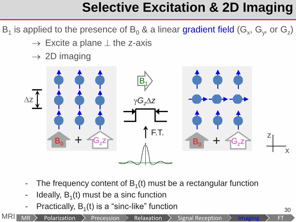
30 30
MRI MR Polarization Precession Relaxation Signal Reception
z
- The frequency content of B1(t) must be a rectangular function
- Ideally, B1(t) must be a sinc function
- Practically, B1(t) is a “sinc-like” function
Gzz
F.T.
Selective Excitation & 2D Imaging
B0
B1
Gzz + B0 Gzz +
Imaging FT
z
x
B1 is applied to the presence of B0 & a linear gradient field (Gx, Gy, or Gz)
Excite a plane the z-axis
2D imaging

Step 1: Selective excitation: B1 is applied to the presence of B0 & Gz
2D Imaging Sequence
Preferred
situation:
in phase
RF coil (excitation)
B1
31 31
MRI MR Polarization Precession Relaxation Signal Reception
RF
Gz
t
z
B0
B1
Gzz + B0 Gzz +
Imaging FT
z
x

2D Imaging Sequence
32 32
MRI MR Polarization Precession Relaxation Signal Reception
RF
Gz
t
Gy
Gx
? ?
RF coil (reception)
B1 z
x
y
RF sources
(x1,y1) (x2,y2)
(x3,y3)
Imaging FT
Step 2: Spatial signal encoding & signal readout
zGG zz
zGG yy
zGG xx
Example:
Gx = 1 Gauss /m
so xGzGBB xzz 0
x
z
zGB z0
-1 0 1 2
xz GzGB 0
xz GzGB 0
xz GzGB 20

2D Imaging Sequence
33 33
MRI MR Polarization Precession Relaxation Signal Reception
Method 1 Projection-reconstruction method
RF
Gz
Gy
Gx
t
Imaging FT
x y
Step 2: Spatial signal encoding & signal readout
t1
At t1, after excitation t > t1
RF coil (reception)
B1 z
x
y
RF sources
(x1,y1) (x2,y2)
(x3,y3)
)( 0 zGB z
)( 0 xtGB x
t < t1
t > t1

2D Imaging Sequence
RF coil (reception)
B1
34 34
MRI MR Polarization Precession Relaxation Signal Reception
z
x
y
RF sources
(x1,y1) (x2,y2)
(x3,y3)
Method 1 Projection-reconstruction method
RF
Gz
Gy
Gx
t
Imaging FT
dxedyyxm
dxdyeyxmts
x
xtGi
y
x y
xtGi
x
x
]),([
),()(
x y
Step 2: Spatial signal encoding & signal readout
)( 0 zGB z
)( 0 xtGB x
At t1, after excitation t > t1
t < t1
t > t1

2D Imaging Sequence
RF coil (reception)
B1
35 35
MRI MR Polarization Precession Relaxation Signal Reception
z
x
y
RF sources
(x1,y1) (x2,y2)
(x3,y3)
Method 1 Projection-reconstruction method
RF
Gz
Gy
Gx
t
Imaging FT
x y
dxexg
dxedyyxm
dxdyeyxmts
x
xtGix
xtGi
y
x y
xtGi
x
x
x
)(
]),([
),()(
g(x) is the
projection of
m(x,y) along the
y-direction
y
dyyxmxg ),()(
Step 2: Spatial signal encoding & signal readout
)( 0 zGB z
)( 0 xtGB x
At t1, after excitation
t > t1
t < t1
t > t1

2D Imaging Sequence
36 36
MRI MR Polarization Precession Relaxation Signal Reception
Method 1 Projection-reconstruction method (with an angle)
RF
Gz
t
Gy
Gx
cosGGx
sinGGy
kx
ky
Imaging FT
Step 2: Spatial signal encoding & signal readout
RF coil (reception)
B1 z
x
y
RF sources
(x1,y1) (x2,y2)
(x3,y3)
)( 0 zGB z
)( 0 ytGxtGB yx
t < t1
t > t1

2D Imaging Sequence
37 37
MRI MR Polarization Precession Relaxation Signal Reception
In X-ray CT imaging
Each point in
the projection
The sum of the object
distribution along the
appropriate ray path
Method 1 Projection-reconstruction method (with an angle)
- A single project angle DOES NOT
provide spatial information of the object
distribution along the ray path
- Multiple angles are needed.
Imaging FT
Step 2: Spatial signal encoding & signal readout

Step 2: Spatial signal encoding & signal readout
2D Imaging Sequence
RF coil (reception)
B1
38 38
MRI MR Polarization Precession Relaxation Signal Reception
z
x
y
RF sources
(x1,y1) (x2,y2)
(x3,y3)
Method 2 2D Fourier transform method (spatial encoding in a smart way)
RF
Gz
t
Gy
Gx
Phase
encoding
Readout
ty
dxdyeeyxmytsx y
xtGiytGi
yxyy
),();(
Imaging FT

2D Fourier Transform Method
39 39
MRI MR Polarization Precession Relaxation Signal Reception Imaging FT
RF
Gz
t
Gy
Gx
Phase
encoding
Readout
ty
dxdyeeyxmytsx y
xtGiytGi
yxyy
),();(
x y
t0 t1 t2
t > t2

2D Fourier Transform Method
40 40
MRI MR Polarization Precession Relaxation Signal Reception
dxdyeeyxmytsx y
xtGiytGi
yxyy
),();(
t
xx dGtk0
)(2
)(
t
yy dGtk0
)(2
)(
dxdyeyxmtsx y
ytkxtki yx
])()([2
),()(
Let
Signal equation
dxdyeyxmtktkMtsx y
ytkxtki
yxyx
])()([2
),()](),([)(
RF
Gz
t
Gy
Gx
Phase
encoding
Readout
ty
t0 t1 t2
Imaging FT

2D Fourier Transform Method
41 41
MRI MR Polarization Precession Relaxation Signal Reception
kx
ky )(ts
Measurable
x
y ),( yxm
Object
Fourier Transform
dxdyeeyxmytsx y
xtGiytGi
yxyy
),();(
t
xx dGtk0
)(2
)(
t
yy dGtk0
)(2
)(
dxdyeyxmtsx y
ytkxtki yx
])()([2
),()(
Let
Signal equation
dxdyeyxmtktkMtsx y
ytkxtki
yxyx
])()([2
),()](),([)(
Imaging FT
k-space

2D Fourier Transform Method
42 42
MRI MR Polarization Precession Relaxation Signal Reception
dxdyeyxmtktkMtsx y
ytkxtki
yxyx
])()([2
),()](),([)(
kx
ky )(ts
Measurable
x
y ),( yxm
Object
Fourier Transform
Signal equation
Source: www.developer.nvidia.com
Imaging FT
k-space k-space

Step 1: Selective excitation: B1 is applied to the presence of B0 & Gz
2D Imaging Sequence
43 43
MRI MR Polarization Precession Relaxation Signal Reception
Step 2: Spatial signal encoding & signal readout
Method 1 Projection-reconstruction method (x-ray CT)
Method 2 2D Fourier transform method (popular)
RF
Gz
Gy
Gx
t RF
Gz t
Gy
Gx
RF
Gz t
Gy
Gx
Phase
encoding
Readout
ty
Imaging FT

Applications of MRI
• Functional MRI
• Diffusion MRI
• Magnetic resonance spectroscopy
• Real-time MRI
• Interventional MRI
• Magnetic resonance angiography
• Magnetic resonance guided focused ultrasound

Applications of MRI
Functional MRI (fMRI)
- fMRI measures signal changes in the brain that are due to changing
neural activity.
- Compared to anatomical T1-weighted imaging, the brain is scanned at
lower spatial resolution but at a higher temporal resolution (typically
once every 2–3 seconds)
Diffusion MRI
- Diffusion MRI measures the diffusion of water molecules in biological
tissues.
- Clinically, diffusion MRI
• Is useful for the diagnoses of conditions (e.g., stroke) or
neurological disorders (e.g., multiple sclerosis)
• Helps better understand the connectivity of white matter axons in
the central nervous system
Source: http://en.wikipedia.org/wiki/Magnetic_resonance_imaging#Specialized_applications

Applications of MRI
Magnetic resonance spectroscopy (MRS)
- MRS is used to measure the levels of different metabolites in body
tissues.
- The MR signal produces a spectrum of resonances that corresponds to
different molecular arrangements of the isotope being "excited".
- This signature is used
• to diagnose certain metabolic disorders, especially those affecting
the brain
• to provide information on tumor metabolism
Source: http://en.wikipedia.org/wiki/Magnetic_resonance_imaging#Specialized_applications

* Take Home Message
• The physical process of MRI
Polarization Precession Relaxation Signal Reception Imaging MR
• Imaging sequence
Step 1: excitation
Step 2: signal encoding & signal readout
• 2D FT method
dxdyeyxmtktkMtsx y
ytkxtki
yxyx
])()([2
),()](),([)(
Signal equation
47
• Three main fields: Main field, B0
RF field, B1
Linear gradient field, G

for your attention!


![Mallard -v- The Queen - [2003] WASCA 296 - Polygraphantipolygraph.org/litigation/mallard/mallard-v-the-queen.pdf · committed by the killer - Whether genuine "confession" or mere](https://img.dokumen.tips/doc/110x75/5a86f9c27f8b9afc5d8d7bcc/mallard-v-the-queen-2003-wasca-296-po-by-the-killer-whether-genuine-confession.jpg)