Embed Size (px)
Citation preview
B a s i c s o f E x p l o s i o n P r o t e c t i o n
I n t r o d u c t i o n t o E x p l o s i o n P r o t e c t i o n f o r E l e c t r i c a l A p p a r a t u s a n d I n s t a l l a t i o n s
1 234
5 6
2
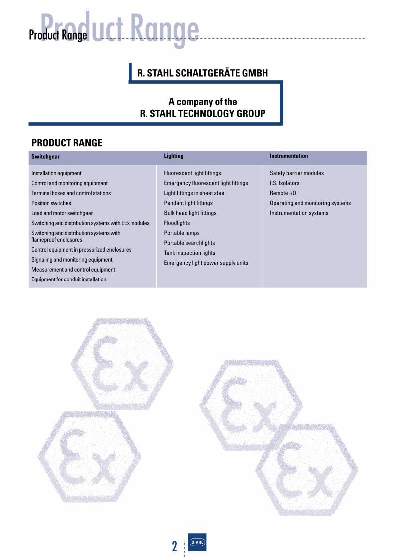
Product RangeProduct Range
R. STAHL SCHALTGERÄTE GMBH
A company of theR. STAHL TECHNOLOGY GROUP
PRODUCT RANGESwitchgear
Installation equipment
Control and monitoring equipment
Terminal boxes and control stations
Position switches
Load and motor switchgear
Switching and distribution systems with EEx modules
Switching and distribution systems withflameproof enclosures
Control equipment in pressurized enclosures
Signaling and monitoring equipment
Measurement and control equipment
Equipment for conduit installation
Lighting
Fluorescent light fittings
Emergency fluorescent light fittings
Light fittings in sheet steel
Pendant light fittings
Bulk head light fittings
Floodlights
Portable lamps
Portable searchlights
Tank inspection lights
Emergency light power supply units
Instrumentation
Safety barrier modules
I.S. Isolators
Remote I/O
Operating and monitoring systems
Instrumentation systems

1 234
5 6
3
IntroductionIntroduction
It is a fact that gases, vapours and mists escape during the production, processing, transportation and storage of flamma-ble materials in the chemical and petrochemical industries, aswell as in the production of mineral oil and natural gas, in miningand in many other sectors. During many processes alsoflammable dusts are created. These flammable gases,vapours, mists and dusts, form an explosive atmosphere withthe oxygen of the air. In the case that this atmosphere is ignited,explosions take place which can result in severe harm tohuman life and property
To avoid the danger of explosions, protective regulations inform of laws, specifications and standards have been developed in most countries and are aimed at ensuring that ahigh level of safety is observed. Due to the growing internationaleconomic link, extensive progress has been made in harmoni-zing the regulations for the explosion protection. The conditionsfor a complete harmonization have been created in the Euro-pean Union by the 9/94 EC Directive. However, world-widethere is still much to be done in this area.
The aim of this brochure is to provide both experts and interested laymen with an overview in the field of explosionprotection; in conjunction with electrical apparatus and installations, it does not replace the study of the relevant sta-tutory regulations and applicable standards.
In mining, miners underground have always lived under thethreat of firedamp explosions. Herein lie the origins of explosion protection, which has been consistently developedin industrialized countries and now provides a high level ofsafety.
Picture of a pit explosion
4
ContentsContents
The basic physic Principles and Definitions of Explosion Protection
Statutory Regulations and Standards2.1 International Standards2.2 European Directives and Standards2.2.1 Introduction2.2.2 EC Directive 94/9/EC (ATEX 100a)2.2.3 Certification and Marking2.3 Statutory Regulations in Germany
Technical Principles3.1 Zone Classification3.2 Explosion Groups and Temperature Classes3.3 Types of Protection3.3.1 Application and Combination of Types of Protection ”d” and ”e”3.3.2 Applications of Type of Protection “Intrinsic Safety“
Installation and Operation of Electrical Equipment4.1 Duties of Installer, Manufacturer and Operator4.2 Classification of Zones and Selection of Apparatus4.3 Methods of Installation4.4 Repair and Maintenance
Explosion Protection in North America5.1 Introduction5.2 Classification of Hazardous Locations5.3 Regulations for Installation5.4 Constructional Requirements5.5 Degrees of Protection provided by Enclosures5.6 Certification and Marking
Appendix6.1 Comparison of IEC Publications and European Standards (EN)6.2 Safety Characteristics of Flammable Gases and Vapours6.3 Classification of Hazardous Locations in North America6.4 Constructional Requirements in North America6.5 Degrees of Protection to IEC 60529 – IPXX6.6 Degrees of Protection to NEMA Standards6.7 Overview of the most important Approval and Testing Authorities
Literature
Index
12
3
4
5
6

1 234
5 6
5
Page 6-7
Page 8-10
Page 11-15
Page 16-17
Page 18-19
Page 20-26
Page 28
Page 29
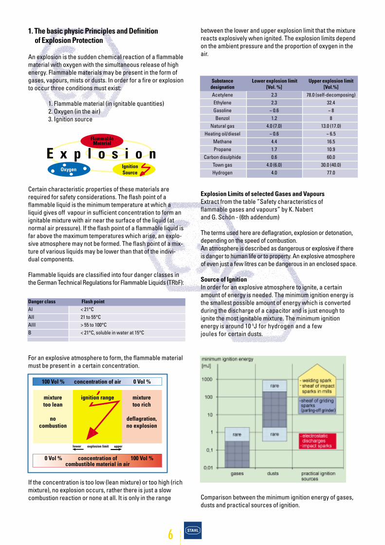
mixturetoo lean
nocombustion
mixturetoo rich
deflagration,no explosion
lower explosion limit upper
concentration of air
concentration ofcombustible material in air
0 Vol % 100 Vol %
100 Vol % 0 Vol %
ignition range
brennbarer Stoff
ZündquelleSauerstoff
E x p l o s i o n
6
between the lower and upper explosion limit that the mixturereacts explosively when ignited. The explosion limits dependon the ambient pressure and the proportion of oxygen in theair.
Explosion Limits of selected Gases and VapoursExtract from the table ”Safety characteristics of flammable gases and vapours” by K. Nabert and G. Schön - (6th addendum)
The terms used here are deflagration, explosion or detonation,depending on the speed of combustion. An atmosphere is described as dangerous or explosive if thereis danger to human life or to property. An explosive atmosphereof even just a few litres can be dangerous in an enclosed space.
Source of IgnitionIn order for an explosive atmosphere to ignite, a certain amount of energy is needed. The minimum ignition energy isthe smallest possible amount of energy which is convertedduring the discharge of a capacitor and is just enough toignite the most ignitable mixture. The minimum ignitionenergy is around 10-5J for hydrogen and a few joules for certain dusts.
Comparison between the minimum ignition energy of gases,dusts and practical sources of ignition.
1. The basic physic Principles and Definition of Explosion Protection
An explosion is the sudden chemical reaction of a flammablematerial with oxygen with the simultaneous release of highenergy. Flammable materials may be present in the form ofgases, vapours, mists or dusts. In order for a fire or explosionto occur three conditions must exist:
1. Flammable material (in ignitable quantities)2. Oxygen (in the air)3. Ignition source
Certain characteristic properties of these materials arerequired for safety considerations. The flash point of aflammable liquid is the minimum temperature at which aliquid gives off vapour in sufficient concentration to form anignitable mixture with air near the surface of the liquid (atnormal air pressure). If the flash point of a flammable liquid isfar above the maximum temperatures which arise, an explo-sive atmosphere may not be formed. The flash point of a mix-ture of various liquids may be lower than that of the indivi-dual components.
Flammable liquids are classified into four danger classes inthe German Technical Regulations for Flammable Liquids (TRbF):
For an explosive atmosphere to form, the flammable materialmust be present in a certain concentration.
If the concentration is too low (lean mixture) or too high (richmixture), no explosion occurs, rather there is just a slowcombustion reaction or none at all. It is only in the range
Danger class Flash pointAI < 21°CAII 21 to 55°CAIII > 55 to 100°CB < 21°C, soluble in water at 15°C
Substance Lower explosion limit Upper explosion limitdesignation [Vol. %] [Vol.%]Acetylene 2.3 78.0 (self-decomposing)Ethylene 2.3 32.4Gasoline ~ 0.6 ~ 8Benzol 1.2 8
Natural gas 4.0 (7.0) 13.0 (17.0)Heating oil/diesel ~ 0.6 ~ 6.5
Methane 4.4 16.5Propane 1.7 10.9
Carbon disulphide 0.6 60.0Town gas 4.0 (6.0) 30.0 (40.0)Hydrogen 4.0 77.0
Flammable Material
IgnitionSource
Oxygen
7
Ignition can be caused by various sources:
• hot surfaces• electrical arcs and sparks• electrostatic discharge• atmospheric discharge (lightning)• mechanical friction or impact sparks• electromagnetic radiation• ultrasonics• adiabatic compression (shock waves) • ionizing radiation• optical radiation• chemical reactions• open flames
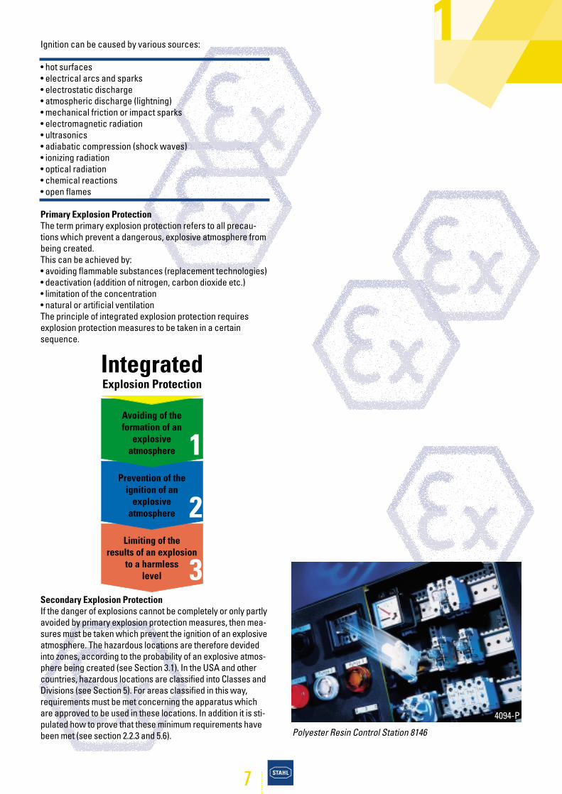
Primary Explosion ProtectionThe term primary explosion protection refers to all precau-tions which prevent a dangerous, explosive atmosphere frombeing created.This can be achieved by:• avoiding flammable substances (replacement technologies)• deactivation (addition of nitrogen, carbon dioxide etc.)• limitation of the concentration• natural or artificial ventilationThe principle of integrated explosion protection requiresexplosion protection measures to be taken in a certainsequence.
Secondary Explosion Protection If the danger of explosions cannot be completely or only partlyavoided by primary explosion protection measures, then mea-sures must be taken which prevent the ignition of an explosiveatmosphere. The hazardous locations are therefore devidedinto zones, according to the probability of an explosive atmos-phere being created (see Section 3.1). In the USA and othercountries, hazardous locations are classified into Classes andDivisions (see Section 5). For areas classified in this way,requirements must be met concerning the apparatus whichare approved to be used in these locations. In addition it is sti-pulated how to prove that these minimum requirements havebeen met (see section 2.2.3 and 5.6).
Avoiding of theformation of an
explosive atmosphere
Prevention of theignition of an
explosiveatmosphere
Limiting of theresults of an explosion
to a harmlesslevel
1
2
3
Integrated Explosion Protection
1
4094-P
Polyester Resin Control Station 8146
8
2. Statutory Regulations and Standards
2.1 International StandardsThe IEC (International Electrotechnical Commission) is responsible for international standardization in the field ofelectrical technology. IEC publications which deal withexplosion protection for electrical apparatus and installations,are developed by the Technical Committee TC31. IEC publica-tions have the status of recommendations which are used for orientation purposes for national and regional standards(see Appendix 6.1). The IEC has introduced a procedure - the so called IEC-ExScheme - intended to become a globally recognized test andcertification procedure in the field of explosion protected elec-trical apparatus. Many technical and legal hurdles still have tobe overcome before this procedure can operate world-wide.
2.2 European Directives and Standards
2.2.1 IntroductionAlready in 1976 the Council of the European Community esta-blished the prerequisite for unrestricted trade of explosionprotected electrical equipment within the European Unionby ratifying the ”Directive on the harmonization of the laws ofthe member states concerning electrical equipment for usein potentially explosive atmospheres (76/117/EEC)”.This directive has since then been supplemented by furtherdirectives. Complete harmonization in this area was achieved in 1994with the new Directive 94/9/EC. Of course, in addition to auniform statutory regulation, uniform standards are requiredas well. CENELEC is the European Committee for Electrotech-nical Standardization in which the countries of the EuropeanUnion and the West European EFTA states cooperate. European standards (EN) are published in three official versi-ons (French, English and German). The members of CENELECare obliged to adopt the European Standards unchanged asnational standards.
The European Standards series EN 50 014 and followingwhich deal with electrical explosion protection, have beendeveloped by the Technical Committee CENELEC TC31 andadopted in the EU states as identical national standards (seetable below).
It is determined that the member states of the EuropeanUnion may not forbid the free trade of electrical apparatus, ifit complies with these standards and has a Certificate ofConformity from a recognized EC testing authority.
The European directives and the uniform standards in thefield of electrical explosion protection have proved to be veryworthwhile in practice.
2.2.2 EC Directive 94/9/EC (ATEX 100a)The EC Directive 94/9/EC was issued in 1994 to further standardize explosion protection and make correspondingadjustments in line with a new directive concept. It specifiesthe requirements for explosion protected equipment and pro-tective systems by prescribing essential health and safetyrequirements. It guarantees the free trade within the Euro-pean Community, as agreed in Article 100a of the Treaty esta-blished between the European Community member states.This is also where the term ATEX 100a, generally used amongthe experts , comes from.
The directive applies to all industrial potentially explosive areas including mining and also covers dustexplosion protection. The scope covers all electrical andmechanical equipment and protective systems. In addition tothe basic health and safety requirements, the classificationof the equipment and protective systems according to cate-gories has also been re-organized, as well as the certification andmarking of these.
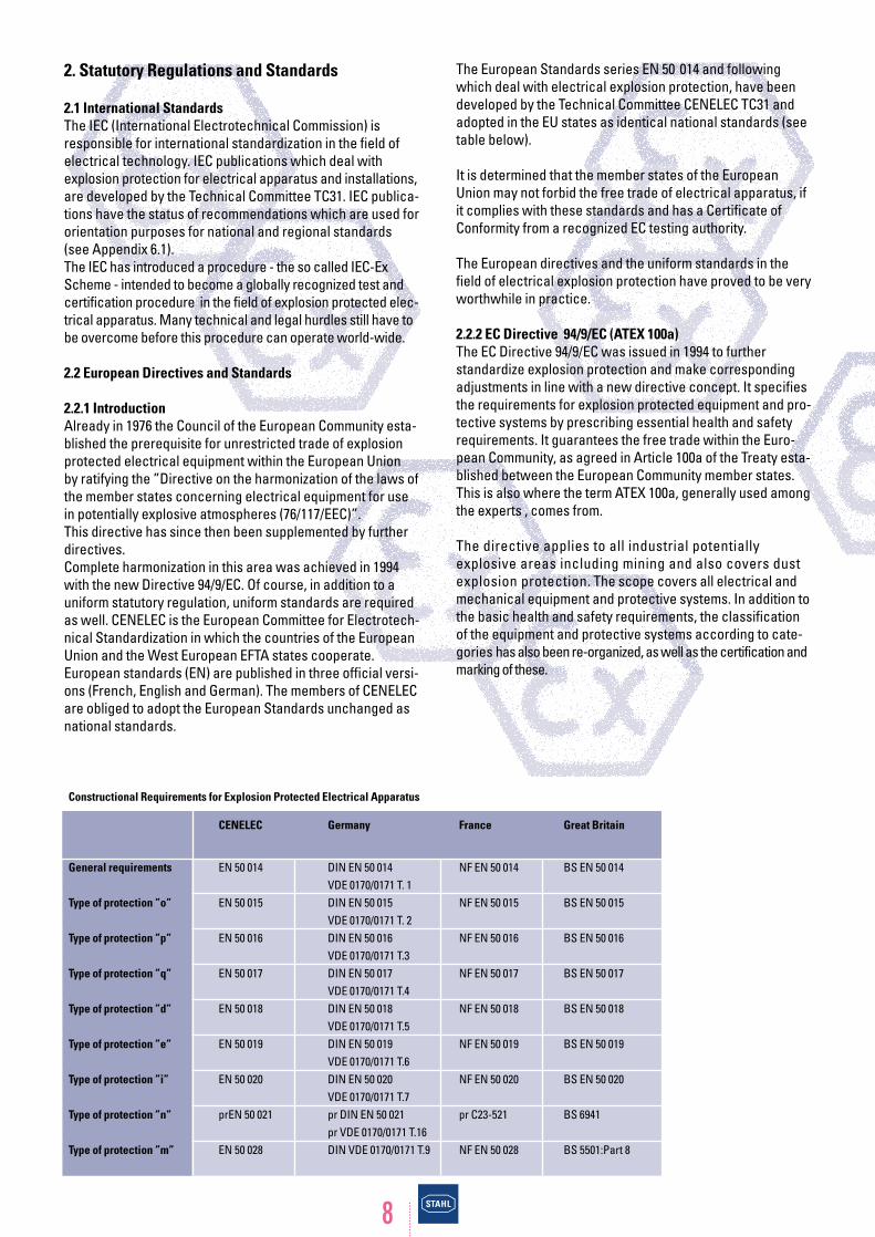
Constructional Requirements for Explosion Protected Electrical Apparatus
CENELEC Germany France Great Britain
General requirements EN 50 014 DIN EN 50 014 NF EN 50 014 BS EN 50 014VDE 0170/0171 T. 1
Type of protection ”o” EN 50 015 DIN EN 50 015 NF EN 50 015 BS EN 50 015VDE 0170/0171 T. 2
Type of protection ”p” EN 50 016 DIN EN 50 016 NF EN 50 016 BS EN 50 016VDE 0170/0171 T.3
Type of protection ”q” EN 50 017 DIN EN 50 017 NF EN 50 017 BS EN 50 017VDE 0170/0171 T.4
Type of protection ”d” EN 50 018 DIN EN 50 018 NF EN 50 018 BS EN 50 018VDE 0170/0171 T.5
Type of protection ”e” EN 50 019 DIN EN 50 019 NF EN 50 019 BS EN 50 019VDE 0170/0171 T.6
Type of protection ”i” EN 50 020 DIN EN 50 020 NF EN 50 020 BS EN 50 020VDE 0170/0171 T.7
Type of protection ”n” prEN 50 021 pr DIN EN 50 021 pr C23-521 BS 6941pr VDE 0170/0171 T.16
Type of protection ”m” EN 50 028 DIN VDE 0170/0171 T.9 NF EN 50 028 BS 5501:Part 8
9
Definitions• ”Electrical installations” are individual or interconnecteditems of apparatus for the generation, conversion, storage,transmission, distribution, measurement, regulation, andconsumption of electrical energy.• ”Equipment” means machines, apparatus, fixed or mobiledevices, control components and instrumentation thereof anddetection or prevention systems which, separately or jointly,are intended for the generation, transfer, storage, measure-ment, control and conversion of energy for the processing ofmaterial and which are capable of causing an explosionthrough their own potential sources of ignition. • ”Protective systems” is the definition for design units whichare intended to halt incipient explosions immediately and / orto limit the effective range of explosion flames and explosionpressures. Protective systems may be integrated into equip-ment separately placed on the market for use as autonomoussystems. The components of the above defined equipmentare not to be considered ”protective systems”.•”Components” means any item essential for the safe func-tioning of equipment and protective systems but with noautonomous function • An ”explosive atmosphere” is a mixture with air, underatmospheric condition, of flammable substances in the formof gases, vapours, mists, or dusts in which, after ignition hasoccured, combustion spreads to the entire unburned mixture.
• A ”potentially explosive atmos-phere” is an atmosphere whichcould become explosive due tolocal and operational conditions.
ScopeThe directive applies to equipment and protec-tive systems for use in potentially explosive atmos-pheres. Safety devices intended for use outside potentiallyexplosive atmospheres but required for or contributing to thesafe functioning of equipment with respect to explosion arealso covered by the scope of this Directive. The DirectiveATEX 100a doesn’t include a reference to mandatory stan-dards, whereas specifies the essential health and safetyrequirements to be maintained and which are mandatory forthe design and construction. The protection against otherhazards (e.g. electric shock) which could be caused by thisequipment, is required as well.
2.2.3 Certification and MarkingIn potentially explosive atmospheres only approved and marked equipment is allowed to be used. For the placing onmarket of explosion protected equipment two directivesapply in parallel.
2
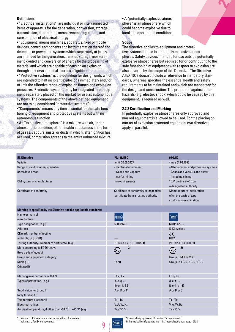
1) With an ... X if reference special conditions for use etc.With a ... U for Ex components
2) new: always present, old: not on Ex components3) Intrinsically safe apparatus: ib / associated apparatus: [ ib ]
EC Directive 79/196/EEC 94/9/ECValidity until 30.06.2003 since 01.03.1996Range of validity for equipment in - Electrical equipment - All equipment and protective systemshazardous areas - Gases and vapours - Gases and vapours and dusts
- not for mining - including miningQM system of manufacturer no requirements ”QM certificate” from
a designated authorityCertificate of conformity Certificate of conformity or inspection Manufacturer’s declaration
certificate from a resting authority of on the basis of type conformity examination
Marking is specified by the Directive and the applicable standardsName or mark ofmanufacturer Type designation, (e.g.) 6000/562-.... 6000/562-....Address — D-KünzelsauCE mark, number of testingauthority, (e.g. PTB) — 0102Testing authority, Number of certificate, (e.g.) PTB No. Ex- 91.C.1045 1) PTB 97 ATEX 2031 1)Mark according to EC Directive 2) 2)(free trade of goods)Group and equipment category: Group I: M 1 or M 2Mining (I) I or II Group II: 1 G/D, 2 G/D, 3 G/DOthers (II)
Marking in accordance with EN EEx / Ex EEx / ExTypes of protection, (e.g.) d, e, q, ... d, e, q, ...
ib or [ ib ] 3) ib or [ ib ] 3)Subdivision for Group Il A or B or C A or B or C(only for d and i)Temperature class for II T1 - T6 T1 - T6Electrical ratings V, A, W, Hz V, A, W, HzAmbient temperature, if other than -20 °C ... +40 °C, (e.g.) Ta ≤ 50 °c Ta ≤50 °c
10
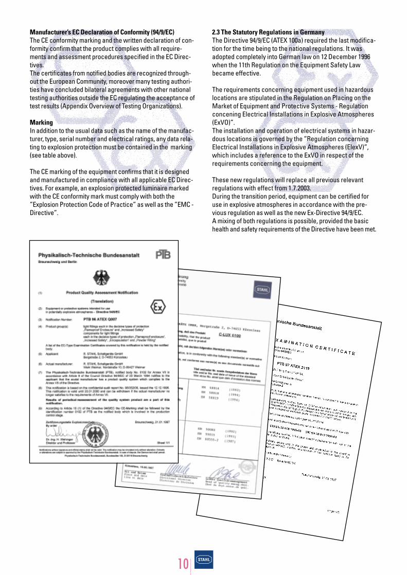
Manufacturer’s EC Declaration of Conformity (94/9/EC)The CE conformity marking and the written declaration of con-formity confirm that the product complies with all require-ments and assessment procedures specified in the EC Direc-tives.The certificates from notified bodies are recognized through-out the European Community, moreover many testing authori-ties have concluded bilateral agreements with other nationaltesting authorities outside the EC regulating the acceptance oftest results (Appendix Overview of Testing Organizations).
MarkingIn addition to the usual data such as the name of the manufac-turer, type, serial number and electrical ratings, any data rela-ting to explosion protection must be contained in the marking(see table above).
The CE marking of the equipment confirms that it is designedand manufactured in compliance with all applicable EC Direc-tives. For example, an explosion protected luminaire markedwith the CE conformity mark must comply with both the”Explosion Protection Code of Practice” as well as the ”EMC -Directive”.
2.3 The Statutory Regulations in GermanyThe Directive 94/9/EC (ATEX 100a) required the last modifica-tion for the time being to the national regulations. It wasadopted completely into German law on 12 December 1996when the 11th Regulation on the Equipment Safety Lawbecame effective.
The requirements concerning equipment used in hazardouslocations are stipulated in the Regulation on Placing on theMarket of Equipment and Protective Systems - Regulationconcening Electrical Installations in Explosive Atmospheres(ExVO)”.The installation and operation of electrical systems in hazar-dous locations is governed by the ”Regulation concerning Electrical Installations in Explosive Atmospheres (ElexV)”,which includes a reference to the ExVO in respect of therequirements concerning the equipment.
These new regulations will replace all previous relevantregulations with effect from 1.7.2003. During the transition period, equipment can be certified foruse in explosive atmospheres in accordance with the pre-vious regulation as well as the new Ex-Directive 94/9/EC. A mixing of both regulations is possible, provided the basichealth and safety requirements of the Directive have been met.
which can also occur in theseareas must be further classified as shown in Group II.
Electrical apparatus in Group II isfurther classified into explosion groups and temperature classes.
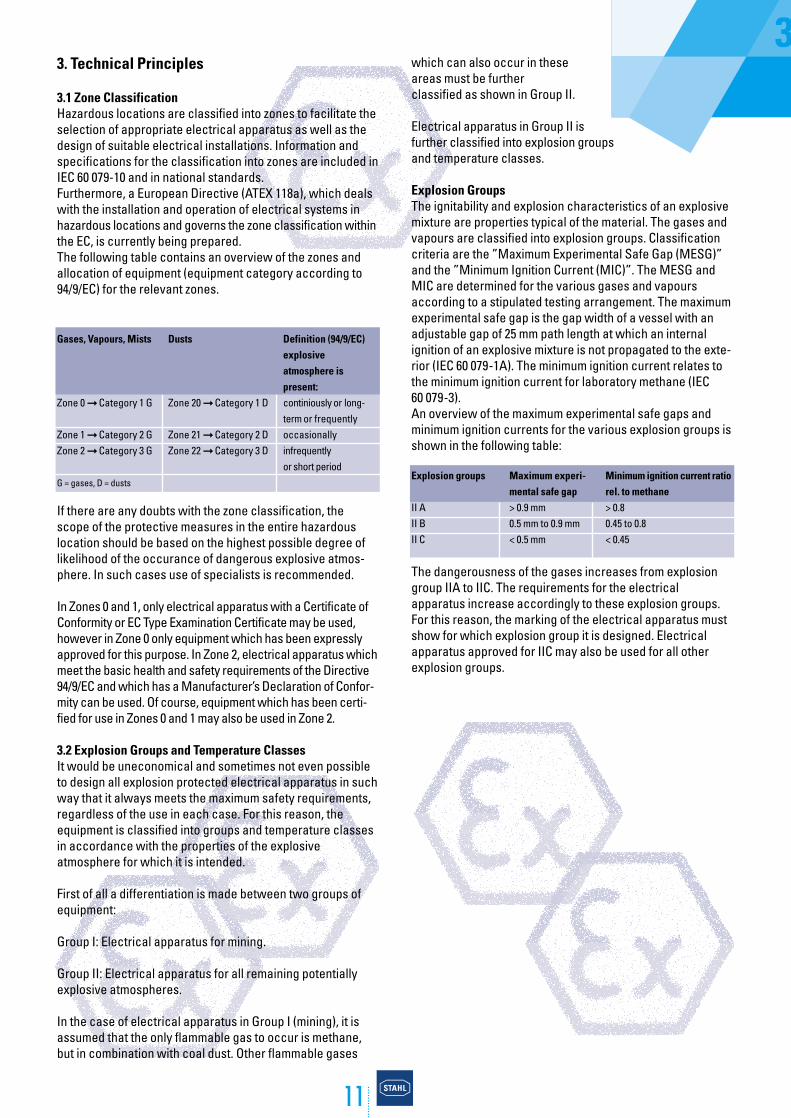
Explosion GroupsThe ignitability and explosion characteristics of an explosivemixture are properties typical of the material. The gases andvapours are classified into explosion groups. Classificationcriteria are the ”Maximum Experimental Safe Gap (MESG)”and the ”Minimum Ignition Current (MIC)”. The MESG andMIC are determined for the various gases and vapoursaccording to a stipulated testing arrangement. The maximumexperimental safe gap is the gap width of a vessel with anadjustable gap of 25 mm path length at which an internalignition of an explosive mixture is not propagated to the exte-rior (IEC 60 079-1A). The minimum ignition current relates tothe minimum ignition current for laboratory methane (IEC 60 079-3).An overview of the maximum experimental safe gaps andminimum ignition currents for the various explosion groups isshown in the following table:
Explosion groups Maximum experi- Minimum ignition current ratiomental safe gap rel. to methane
II A > 0.9 mm > 0.8II B 0.5 mm to 0.9 mm 0.45 to 0.8II C < 0.5 mm < 0.45
The dangerousness of the gases increases from explosiongroup IIA to IIC. The requirements for the electrical apparatus increase accordingly to these explosion groups.For this reason, the marking of the electrical apparatus mustshow for which explosion group it is designed. Electricalapparatus approved for IIC may also be used for all otherexplosion groups.
11
3. Technical Principles
3.1 Zone ClassificationHazardous locations are classified into zones to facilitate theselection of appropriate electrical apparatus as well as thedesign of suitable electrical installations. Information andspecifications for the classification into zones are included inIEC 60 079-10 and in national standards.Furthermore, a European Directive (ATEX 118a), which dealswith the installation and operation of electrical systems inhazardous locations and governs the zone classification withinthe EC, is currently being prepared.The following table contains an overview of the zones andallocation of equipment (equipment category according to94/9/EC) for the relevant zones.
If there are any doubts with the zone classification, thescope of the protective measures in the entire hazardouslocation should be based on the highest possible degree oflikelihood of the occurance of dangerous explosive atmos-phere. In such cases use of specialists is recommended.
In Zones 0 and 1, only electrical apparatus with a Certificate ofConformity or EC Type Examination Certificate may be used,however in Zone 0 only equipment which has been expresslyapproved for this purpose. In Zone 2, electrical apparatus whichmeet the basic health and safety requirements of the Directive94/9/EC and which has a Manufacturer’s Declaration of Confor-mity can be used. Of course, equipment which has been certi-fied for use in Zones 0 and 1 may also be used in Zone 2.
3.2 Explosion Groups and Temperature ClassesIt would be uneconomical and sometimes not even possibleto design all explosion protected electrical apparatus in suchway that it always meets the maximum safety requirements,regardless of the use in each case. For this reason, theequipment is classified into groups and temperature classesin accordance with the properties of the explosive atmosphere for which it is intended.
First of all a differentiation is made between two groups of equipment:
Group I: Electrical apparatus for mining.
Group II: Electrical apparatus for all remaining potentially explosive atmospheres.
In the case of electrical apparatus in Group I (mining), it isassumed that the only flammable gas to occur is methane,but in combination with coal dust. Other flammable gases
3
Gases, Vapours, Mists Dusts Definition (94/9/EC) explosive atmosphere is present:
Zone 0 ➞ Category 1 G Zone 20 ➞ Category 1 D continiously or long-term or frequently
Zone 1 ➞ Category 2 G Zone 21 ➞ Category 2 D occasionallyZone 2 ➞ Category 3 G Zone 22 ➞ Category 3 D infrequently
or short periodG = gases, D = dusts
12
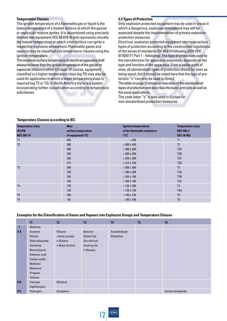
Temperature ClassesThe ignition temperature of a flammable gas or liquid is thelowest temperature of a heated surface at which the gas/airor vapour/air mixture ignites. It is ascertained using preciselydefined test equipment (IEC 60 079-4) and represents virtuallythe lowest temperature at which a hot surface can ignite arespective explosive atmosphere. Flammable gases andvapours may be classified into temperature classes using theignition temperature.The maximum surface temperature of electrical apparatus shallalways be lower than the ignition temperature of the gas/air orvapour/air mixture in which it is used. Of course, equipment classified in a higher temperature class (eg T5) may also beused for application in which a lower temperature class isrequired (eg T2 or T3). In North America there is a systemincorporating further classification according to temperaturesubclasses.
Examples for the Classification of Gases and Vapours into Explosion Groups and Temperature Classes
3.3 Types of ProtectionOnly explosion protected equipment may be used in areas inwhich a dangerous, explosive atmosphere may still beexpected despite the implementation of primary explosionprotection measures.Electrical, explosion protected equipment can have varioustypes of protection according to the construction regulationsof the series of standards EN 50 014 following (DIN VDE0170/0171 Part 1 - following). The type of protection used bythe manufacturer for apparatus essentially depends on thetype and function of the apparatus. From a safety point ofview, all standardized types of protection should be seen asbeing equal, but it should be noted here that the type of pro-tection ”n”can only be used in Zone 2.The table on page 13 shows an overview of the standardizedtypes of protection and describes the basic principle as well asthe usual applications.The code letter ”s” is also used in Europe fornon-standardized protection measures.
Temperature Classes according to IEC
Temperature class Max. Ignition temperatures Temperature classIEC/EN surface temperature of the flammable substance NEC 500-3NEC 505-10 of equipment [°C] [°C] CEC 18-052T1 450 > 450 T1T2 300 > 300 ≤ 450 T2
280 > 280 ≤ 300 T2A260 > 260 ≤ 280 T2B230 > 230 ≤ 260 T2C215 > 215 ≤ 230 T2D
T3 200 > 200 ≤ 300 T3180 > 180 ≤ 200 T3A165 > 165 ≤ 180 T3B160 > 160 ≤ 165 T3C
T4 135 > 135 ≤ 200 T4120 > 120 ≤ 135 T4A
T5 100 > 100 ≤ 135 T5T6 85 > 85 ≤ 100 T6
T1MethaneAcetoneEthaneEthyl ethanoateAmmoniaBenzol (pure)Ethanoic acidCarbon oxideMethaneMethanolPropaneTolueneCoal gas(lighting gas)Hydrogen
T2
Ethanoli-Amyl acetaten-Butanen-Butyl alcohol
Ethylene
Acetylene
T3
BenzineDiesel fuelAircraft fuelHeating oilsn-Hexane
T4
AcetaldehydeEthylether
III A
II B
II C
T5 T6
Carbon disulphide
13
Zone 2This type of protection includes several methods ofignition protection.
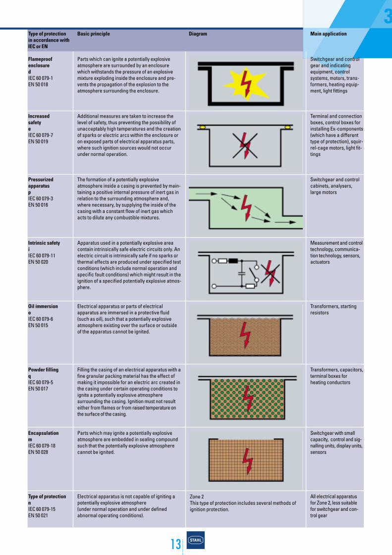
Type of protection in accordance withIEC or EN
FlameproofenclosuredIEC 60 079-1EN 50 018
IncreasedsafetyeIEC 60 079-7EN 50 019
PressurizedapparatuspIEC 60 079-3EN 50 016
Intrinsic safetyiIEC 60 079-11EN 50 020
Oil immersionoIEC 60 079-6EN 50 015
Powder fillingqIEC 60 079-5EN 50 017
EncapsulationmIEC 60 079-18EN 50 028
Type of protectionnIEC 60 079-15EN 50 021
Basic principle
Parts which can ignite a potentially explosiveatmosphere are surrounded by an enclosurewhich withstands the pressure of an explosivemixture exploding inside the enclosure and pre-vents the propagation of the explosion to theatmosphere surrounding the enclosure.
Additional measures are taken to increase thelevel of safety, thus preventing the possibility ofunacceptably high temperatures and the creationof sparks or electric arcs within the enclosure oron exposed parts of electrical apparatus parts,where such ignition sources would not occurunder normal operation.
The formation of a potentially explosive atmosphere inside a casing is prevented by main-taining a positive internal pressure of inert gas inrelation to the surrounding atmosphere and,where necessary, by supplying the inside of thecasing with a constant flow of inert gas whichacts to dilute any combustible mixtures.
Apparatus used in a potentially explosive areacontain intrinsically safe electric circuits only. Anelectric circuit is intrinsically safe if no sparks orthermal effects are produced under specified testconditions (which include normal operation andspecific fault conditions) which might result in theignition of a specified potentially explosive atmos-phere.
Electrical apparatus or parts of electrical apparatus are immersed in a protective fluid(such as oil), such that a potentially explosiveatmosphere existing over the surface or outsideof the apparatus cannot be ignited.
Filling the casing of an electrical apparatus with afine granular packing material has the effect ofmaking it impossible for an electric arc created inthe casing under certain operating conditions toignite a potentially explosive atmosphere surrounding the casing. Ignition must not resulteither from flames or from raised temperature onthe surface of the casing.
Parts which may ignite a potentially explosiveatmosphere are embedded in sealing compoundsuch that the potentially explosive atmospherecannot be ignited.
Electrical apparatus is not capable of igniting apotentially explosive atmosphere (under normal operation and under definedabnormal operating conditions).
Diagram
3Main application
Switchgear and controlgear and indicatingequipment, controlsystems, motors, trans-formers, heating equip-ment, light fittings
Terminal and connectionboxes, control boxes forinstalling Ex-components(which have a differenttype of protection), squir-rel-cage motors, light fit-tings
Switchgear and controlcabinets, analysers,large motors
Measurement and controltechnology, communica-tion technology, sensors,actuators
Transformers, startingresistors
Transformers, capacitors,terminal boxes forheating conductors
Switchgear with smallcapacity, control and sig-nalling units, display units,sensors
All electrical apparatusfor Zone 2, less suitablefor switchgear and con-trol gear
14
3.3.1 Application and Combination of Types of Protection ”d” and ”e”The most important type of protection for switchgear is”Flameproof Enclosure”, usually in conjunction with “In-creased Safety”. Switchgear does produce sources of igni-tion in normal use and therefore ”Increased Safety” alone isnot applicable as type of protection for switchgear, since”Increased Safety” is based on the principle to avoid sour-ces of ignition by additional measures. However, ”IncreasedSafety”, in conjunction with ”Flameproof Enclosure”, cut agreat figure for switchgear and control gear.
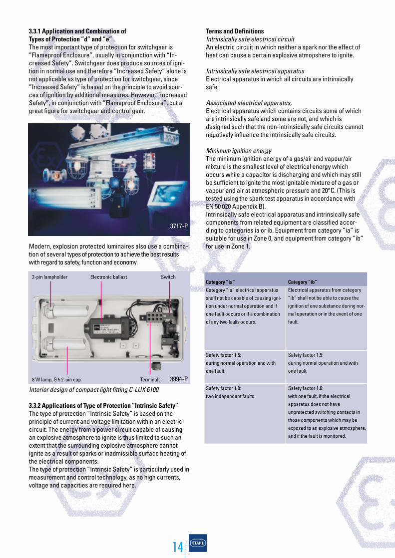
Modern, explosion protected luminaires also use a combina-tion of several types of protection to achieve the best resultswith regard to safety, function and economy.
Interior design of compact light fitting C-LUX 6100
3.3.2 Applications of Type of Protection ”Intrinsic Safety” The type of protection ”Intrinsic Safety” is based on the principle of current and voltage limitation within an electriccircuit. The energy from a power circuit capable of causingan explosive atmosphere to ignite is thus limited to such anextent that the surrounding explosive atmosphere cannotignite as a result of sparks or inadmissible surface heating ofthe electrical components. The type of protection ”Intrinsic Safety” is particularly used inmeasurement and control technology, as no high currents,voltage and capacities are required here.
3717-P
3994-P
2-pin lampholder Electronic ballast Switch
Terminals8 W lamp, G 5 2-pin cap
Terms and DefinitionsIntrinsically safe electrical circuitAn electric circuit in which neither a spark nor the effect ofheat can cause a certain explosive atmopshere to ignite.
Intrinsically safe electrical apparatusElectrical apparatus in which all circuits are intrinsicallysafe.
Associated electrical apparatus, Electrical apparatus which contains circuits some of whichare intrinsically safe and some are not, and which is designed such that the non-intrinsically safe circuits cannotnegatively influence the intrinsically safe circuits.
Minimum ignition energyThe minimum ignition energy of a gas/air and vapour/air mixture is the smallest level of electrical energy whichoccurs while a capacitor is discharging and which may stillbe sufficient to ignite the most ignitable mixture of a gas orvapour and air at atmospheric pressure and 20°C. (This istested using the spark test apparatus in accordance with EN 50 020 Appendix B).Intrinsically safe electrical apparatus and intrinsically safecomponents from related equipment are classified accor-ding to categories ia or ib. Equipment from category ”ia” issuitable for use in Zone 0, and equipment from category ”ib”for use in Zone 1.
Category ”ib”Electrical apparatus from category”ib” shall not be able to cause theignition of one substance during nor-mal operation or in the event of onefault.
Safety factor 1.5: during normal operation and withone fault
Safety factor 1.0:with one fault, if the electrical apparatus does not have unprotected switching contacts inthose components which may beexposed to an explosive atmosphere,and if the fault is monitored.
Category ”ia”Category ”ia” electrical apparatusshall not be capable of causing igni-tion under normal operation and ifone fault occurs or if a combinationof any two faults occurs.
Safety factor 1.5: during normal operation and withone fault
Safety factor 1.0:two independent faults

15
Isolation of Intrinsically Safe Circuits from non-intrinsicallySafe CircuitsAn important measure for intrinsically safe circuits is thesafe isolation of all intrinsically safe circuits from non intrin-sically safe circuits. Safe electric isolation is always required,with the exception of safety barriers. One rule which appliesespecially to Germany is that safety barriers are not permit-ted for the protection of intrinsically safe circuits in Zone 0.Galvanic isolation is generally required for Zone 0.
Zener diodes, used for limiting voltage, as well as other semiconductor components are considered to be suscep-tible to failure and must therefore be safeguarded by meansof redundant components. Wire wound or sheet resistors for current limitation are considered to be infallible components (they have high resistivity in the event of a fault).Therefore one single component is sufficient.
Single fault safety:In the event of the failure of one zener diode, a second zenerdiode must take its function (Category ”ib”: one redundant zener diode)
Double fault safety:In the event of a failure of two zener diodes, a third zenerdiode must take its function (Category ”ia”: two redundantzener diodes)
3Intrinsically safe apparatus
This contains intrinsically safe electric circuits only
EEx ib IIC T6
All necessary information is provided such ascategory, gas group and temperature class.
The apparatus may be used in Zone 1.
Associated electrical apparatus
This contains both intrinsically safe and non-intrinsically safe electric circuits
The square brackets indicate that the associated electrical apparatus contains an intrinsi-cally safe electric circuit which may be introduced into Zone 1, gas groups IIA, IIB and IIC.
[EEx ib] IIC T6
The apparatus must be installed outside ofthe potentially explosive area.
EEx de [ib] IIC T6
The apparatus may be used in zone 1 due toinstallation in a flame-proof enclosure (”d”)
4085-P
Temperature field station
16
4. Installation and Operation of Electrical Appara-tus in Potentially Explosive Areas
4.1 Duties of Installer, Manufacturer and OperatorSafety in potentially explosive areas can only be guaranteedby a close and effective working relationship amongst allparties involved.
The operator is responsible for the safety of his equipment. It ishis duty to judge where there is a risk of explosion and thendivide areas into Zones accordingly. He must ensure that theequipment is installed in accordance with regulations and istested before initial use. The equipment must be kept in a fitstate by regular inspection and maintenance.The installer must observe the installation requirements andselect and install the electric apparatus correctly for its inten-ded use.Manufacturers of explosion protected apparatus are responsi-ble for routine testing, certification and documentation and arerequired to ensure that each device manufactured complieswith the design tested.
4.2 Classification into Zones and Selection of ApparatusThe question of possible risks of explosion must be addressed at the early stages of planning a new facility.When classifying potentially explosive areas, the influenceof natural or artificial ventilation must be considered in addition to the levels of flammable materials being released.Furthermore, the classification figures relating to explosiontechnology must be determined for the flammable materialsbeing used (see Appendix 6.2). Only then a decision can be rea-ched on the division of potentially explosive areas into Zonesand the selection of suitable apparatus. IEC 60 079-14 (DIN 60079-14) applies to the installation of electrical apparatus inpotentially explosive areas Group II.
Equipment shall only be used within the ambient temperaturerange stipulated in its marking. If the marking does not con-tain any information, the standard range of between -20°Cand +40°C does apply.Electrical apparatus with the types of protection ”d” and ”i”must correspond to a subgroup IIA, IIB or IIC.
Electrical apparatus must be selected and installed such thatit is protected against external influences which may adversely affect the explosion protection.
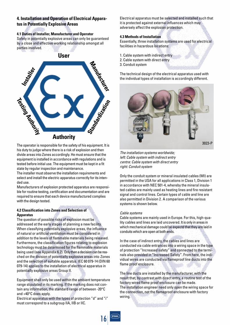
4.3 Methods of Installation Essentially, three installation systems are used for electricalfacilities in hazardous locations:
1. Cable system with indirect entry2. Cable system with direct entry3. Conduit system
The technical design of the electrical apparatus used withthe individual types of installation is accordingly different.
The installation systems worldwide;left: Cable system with indirect entrycentre: Cable system with direct entryright: Conduit system
Only the conduit system or mineral insulated cables (MI) arepermitted in the USA for all applications in Class 1, Division 1in accordance with NEC 501-4, whereby the mineral insula-ted cables are mainly used as heating lines and fire resistantsignal and control lines. Certain types of cable and line arealso permitted in Division 2. A comparison of the varioussystems is shown below.
Cable systemsCable systems are mainly used in Europe. For this, high-qua-lity cables and lines are laid uncovered. It is only in areas inwhich mechanical damage could be expectd that they are laid inconduits which are open at both ends.
In the case of indirect entry, the cables and lines are conducted via cable entrances into a wiring space in the typeof protection ”Increased safety” and connected to the termi-nals also provided in ”Increased Safety”. From here, the indi-vidual wires are conducted via flameproof line ducts into theflame proof enclosure.
The line ducts are installed by the manufacturer, with theresult that, by contrast with direct entry, a routine test of thefactory wired flame proof enclosure can be made.The installation engineer need only open the wiring space forthe connection, not the flameproof enclosure with factorywiring.
3023-P
User
AuthorityM
anufacturer
Testing Authority
Inst
alle
r
Stan
dard
izatio
n
17
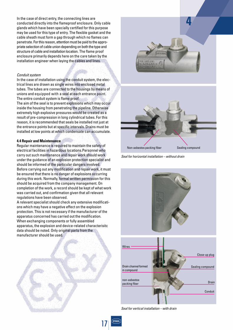
In the case of direct entry, the connecting lines are conducted directly into the flameproof enclosure. Only cableglands which have been specially certified for this purposemay be used for this type of entry. The flexible gasket and thecable sheath must form a gap through which no flames canpenetrate. For this reason, attention must be paid to the appro-priate selection of cable union depending on both the type andstructure of cable and installation location. The flame proofenclosure primarily depends here on the care taken by theinstallation engineer when laying the cables and lines.
Conduit systemIn the case of installation using the conduit system, the elec-trical lines are drawn as single wires into enclosed metaltubes. The tubes are connected to the housings by means ofunions and equipped with a seal at each entrance point.The entire conduit system is flame proof.The aim of the seal is to prevent explosions which may occurinside the housing from penetrating the pipeline. Otherwiseextremely high explosive pressures would be created as aresult of pre-compression in long cylindrical tubes. For thisreason, it is recommended that seals be installed not just atthe entrance points but at specific intervals. Drains must beinstalled at low points at which condensate can accumulate.
4.4 Repair and MaintenanceRegular maintenance is required to maintain the safety ofelectrical facilities in hazardous locations.Personnel whocarry out such maintenance and repair work should workunder the guidance of an explosion protection specialist andshould be informed of the particular dangers involved.Before carrying out any modification and repair work, it mustbe ensured that there is no danger of explosions occurringduring this work. Normally, formal written permission for thisshould be acquired from the company management. On completion of the work, a record should be kept of what workwas carried out, and confirmation given that all relevantregulations have been observed.A relevant specialist should check any extensive modificati-ons which may have a negative effect on the explosion protection. This is not necessary if the manufacturer of theapparatus concerned has carried out the modification.When exchanging components or fully assembled apparatus, the explosion and device-related characterisitcdata should be noted. Only original parts from the manufacturer should be used.
4
Sealing compoundNon-asbestos packing fiber
Seal for horizontal installation – without drain
Seal for vertical installation – with drain
non-asbestospacking fiber Drain
Conduit
Sealing compound
Close-up plug
Wires
Drain channel formed in compound

18
5. Explosion Protection in North America
5.1 IntroductionThe basic principles of explosion protection are the same allover the world. However, technologies have developed in NorthAmerica in the field of explosion protection for electricalequipment and installations which deviate considerably fromthose of the IEC (International Electrotechnical Commission).The differences from IEC technologies are among others the classification of hazardous locations, the construction ofapparatus and the installation of electrical systems.
5.2 Classification of Hazardous LocationsFor potentially explosive atmospheres the term ”hazardous(classified) locations” is used in North America. They aredefined in Articles 500 and 505 of the National Electrical Code(NEC) in the USA and in Section 18 and Annex J of the Cana-dian Electrical Code (CEC) in Canada.The hazardous locati-ons are those locations, where fire or explosion hazards mayexist due to flammable gases, vapours or liquids (Class I),combustible dusts (Class II), or ignitable fibers or flyings(Class III).
Based on the likelihood or risk that an ignitable concentra-tion of a flammable material will be present the hazardouslocations are traditionally subdivided into Division 1 and Divi-sion 2.
In 1996 the IEC classification system was introduced as aparallel system to the existing system for Class I in the USA.This system was implemented by the new Article 505. Thisnow gives the end user the possibility to choose the systemwhich best suits his needs.
The IEC zone classification for Class I was also introduced inCanada (CEC, 1988 edition). All newly built facilities inCanada need to be classified according to this principle.
The traditional North American classification system dividesClass I flammable gases, vapours, mists and liquids into GasGroups A, B, C and D and Class II combustible dusts intoGroups E, F and G.
Group A is the most hazardous gas group in the traditionalNEC system whereas Group IIC is the most volatile in the IECsystem in Article 505 of the NEC.
In Canada both gas grouping systems may be used with thezone classification system.
The maximum surface temperature classification given in thenew Article 505 maintains a pure IEC approach of having sixmain temperature classes T1 to T6. This deviates from thetraditional NEC temperature class structure which has fur-ther subdivisions between the main temperature classes.In the 1998 CEC this traditional structure T1-T6 with interme-diate subdivisions was maintained.
5.3 Regulations for Installation The National Electrical Code in the USA and the CanadianElectrical Code in Canada apply to electrical apparatus andinstallations for hazardous locations.
These have the character of installation regulations for elec-trical facilities in all locations and refer to a number of furtherstandards of other institutions which contain specificationsfor the installation and construction of suitable equipment.
The methods of installation for the zone concept in accor-dance with the NEC are similar to the traditional Class/Divisionsystem. New to the NEC 1996 is the use of listed Metal Clad(MC) cables in addition to rigid conduit and Mineral Insulatedcables in Class I, Division 1 or Zone 1.
One significant advantage of the CEC is the increased possibility of using wires and cables. In contrast to the USA,Canada has, for some time now, also permitted the useof special cables similar to the IEC steel-wire armouredcables.
5.4 Constructional RequirementsThe regulations of the National Electrical Code and the Canadian Electrical Code stipulate which apparatus andmethods of protection may be used in different hazardouslocations.
Various standards and regulations govern the constructionand testing of explosion-protected electrical apparatus andinstallations in North America. In the USA, these are mainlythe standards issued by Underwriters Laboratories Inc. (UL),Factory Mutual Research Corporation (FM) and the Inter-national Society for Measurement and Control (ISA). InCanada, those of the Canadian Standards Association (CSA)apply.
The tables in appendix 6.4 provide an overview of the constructional requirements for hazardous locations andmethods of protection.
5.5 Degrees of Protection provided by Enclosures The standard IEC 60 529 defines the degrees of protectionprovided by enclosures. In the USA the degrees of protec-tion are included in the NEMA Publication No. 250 (NationalElectrical Manufacturing Association). These enclosuretypes could not be exactly equated with the IEC enclosureclassification designation since NEMA additional environ-mental influences (such as cooling lubricant, cutting coo-lant, corrosion, iceing, hail) takes into account.
19
5.6 Certification and MarkingIn the USA and Canada, electrical apparatus and apparatusused in hazardous locations are, as a rule, subject to appro-val. Exceptions to this are items of electrical apparatuswhich, due to their design and the type of the explosiveatmosphere in which they operate, cannot create sparks.The responsible authorities shall decide whether suchequipment is subject to approval.
Equipment which has been developed and manufactured foruse in hazardous locations is tested and approved in the USAand Canada by a recognized testing laboratory. In the USA,this is for example the Underwriters Laboratories or FactoryMutual and in Canada the Canadian Standards Association.
In addition to data such as manufacturer, model, serial numberand electrical data, any data relating to explosion protectionmust be shown on the marking of the equipment. The require-ments for this are specified in the NEC, the CEC as well as therelevant construction regulations of the testing authority.
Class I, II & III, Division 1 and 2The approved electrical equipment for Class I, Class II andClass III, Division 1 and Division 2 must be marked to showthe following information:1. Class(es), Division(s) (optional except for Division 2)2. Gas/dust group(s)3. Operating temperature or temperature class (optional T5
and T6Example: Class I Division 1 Groups C D T6
Class I, Zone 0, 1 and 2For equipment intended for use in Class I, Zone 0, Zone 1 orZone 2, a distinction is made between ”Division Equipment”and ”Zone Equipment”.
(1) Division Equipment: Equipment approved for Class I, Division 1 and/or Class I, Division 2 shall be permitted to bemarked with the following in addition:1. Class I, Zone 1 or Class I, Zone 2 (as applicable)2. Gas group(s) IIA, IIB or IIC3. Temperature classExample: Class I Zone 1 IIC T4
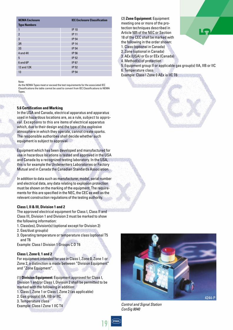
(2) Zone Equipment: Equipmentmeeting one or more of the pro-tection techniques described inArticle 505 of the NEC or Section18 of the CEC shall be marked withthe following in the order shown:1. Class (optional in Canada)2. Zone (optional in Canada)3. AEx (USA) or Ex or EEx (Canada)4. Method(s) of protection5. Equipment group II or applicable gas group(s) IIA, IIB or IIC6. Temperature classExample: Class I Zone 0 AEx ia IIC T6
5
4244-P
NEMA Enclosure IEC Enclosure ClassificationType Numbers1 IP 102 IP 113 IP 543R IP 143S IP 544 and 4X IP 565 IP 526 and 6P IP 6712 and 12K IP 5213 IP 54
Note:As the NEMA Types meet or exceed the test requirements for the associated IEC Classifications the table cannot be used to convert from IEC Classifications to NEMATypes.
Control and Signal StationConSig 8040
20
6. Appendix
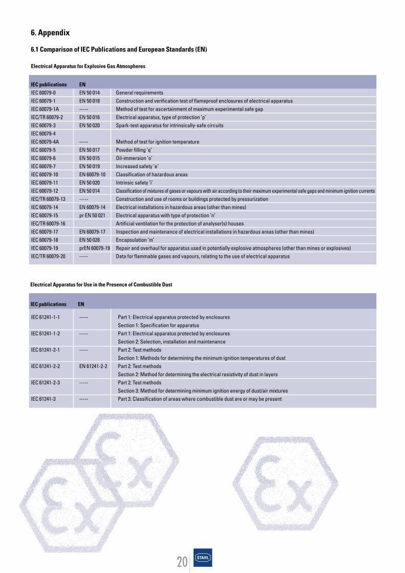
6.1 Comparison of IEC Publications and European Standards (EN)
Electrical Apparatus for Explosive Gas Atmospheres
IEC 61241-1-1 ----- Part 1: Electrical apparatus protected by enclosuresSection 1: Specification for apparatus
IEC 61241-1-2 ----- Part 1: Electrical apparatus protected by enclosuresSection 2: Selection, installation and maintenance
IEC 61241-2-1 ----- Part 2: Test methodsSection 1: Methods for determining the minimum ignition temperatures of dust
IEC 61241-2-2 EN 61241-2-2 Part 2: Test methodsSection 2: Method for determining the electrical resistivity of dust in layers
IEC 61241-2-3 ----- Part 2: Test methodsSection 3: Method for determining minimum ignition energy of dust/air mixtures
IEC 61241-3 ----- Part 3: Classification of areas where combustible dust are or may be present
Electrical Apparatus for Use in the Presence of Combustible Dust
IEC publications ENIEC 60079-0 EN 50 014 General requirementsIEC 60079-1 EN 50 018 Construction and verification test of flameproof enclosures of electrical apparatusIEC 60079-1A ----- Method of test for ascertainment of maximum experimental safe gapIEC/TR 60079-2 EN 50 016 Electrical apparatus, type of protection ’p’IEC 60079-3 EN 50 020 Spark-test apparatus for intrinsically-safe circuitsIEC 60079-4IEC 60079-4A ----- Method of test for ignition temperatureIEC 60079-5 EN 50 017 Powder filling ’q’IEC 60079-6 EN 50 015 Oil-immersion ’o’IEC 60079-7 EN 50 019 Increased safety ’e’IEC 60079-10 EN 60079-10 Classification of hazardous areasIEC 60079-11 EN 50 020 Intrinsic safety ’i’IEC 60079-12 EN 50 014 Classification of mixtures of gases or vapours with air according to their maximum experimental safe gaps and minimum ignition currentsIEC/TR 60079-13 ----- Construction and use of rooms or buildings protected by pressurizationIEC 60079-14 EN 60079-14 Electrical installations in hazardous areas (other than mines)IEC 60079-15 pr EN 50 021 Electrical apparatus with type of protection ’n’IEC/TR 60079-16 Artificial ventilation for the protection of analyser(s) housesIEC 60079-17 EN 60079-17 Inspection and maintenance of electrical installations in hazardous areas (other than mines)IEC 60079-18 EN 50 028 Encapsulation ’m’IEC 60079-19 prEN 60079-19 Repair and overhaul for apparatus used in potentially explosive atmospheres (other than mines or explosives)IEC/TR 60079-20 ----- Data for flammable gases and vapours, relating to the use of electrical apparatus
IEC publications EN
21
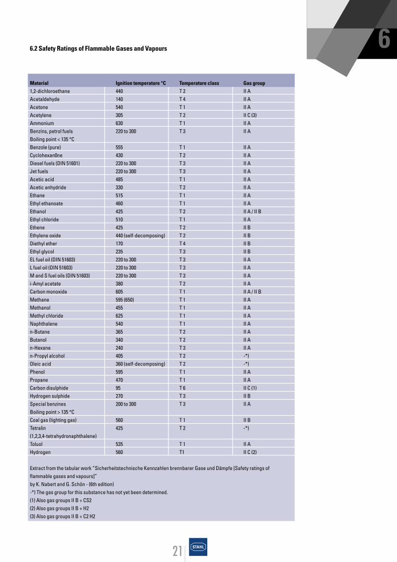
66.2 Safety Ratings of Flammable Gases and Vapours
Material Ignition temperature °C Temperature class Gas group1,2-dichloroethane 440 T 2 II AAcetaldehyde 140 T 4 II AAcetone 540 T 1 II AAcetylene 305 T 2 II C (3)Ammonium 630 T 1 II ABenzins, petrol fuels 220 to 300 T 3 II ABoiling point < 135 °CBenzole (pure) 555 T 1 II ACyclohexan0ne 430 T 2 II ADiesel fuels (DIN 51601) 220 to 300 T 3 II AJet fuels 220 to 300 T 3 II AAcetic acid 485 T 1 II AAcetic anhydride 330 T 2 II AEthane 515 T 1 II AEthyl ethanoate 460 T 1 II AEthanol 425 T 2 II A / II BEthyl chloride 510 T 1 II AEthene 425 T 2 II BEthylene oxide 440 (self-decomposing) T 2 II BDiethyl ether 170 T 4 II BEthyl glycol 235 T 3 II BEL fuel oil (DIN 51603) 220 to 300 T 3 II AL fuel oil (DIN 51603) 220 to 300 T 3 II AM and S fuel oils (DIN 51603) 220 to 300 T 3 II Ai-Amyl acetate 380 T 2 II ACarbon monoxide 605 T 1 II A / II BMethane 595 (650) T 1 II AMethanol 455 T 1 II AMethyl chloride 625 T 1 II ANaphthalene 540 T 1 II An-Butane 365 T 2 II AButanol 340 T 2 II An-Hexane 240 T 3 II An-Propyl alcohol 405 T 2 -*)Oleic acid 360 (self-decomposing) T 2 -*)Phenol 595 T 1 II APropane 470 T 1 II ACarbon disulphide 95 T 6 II C (1)Hydrogen sulphide 270 T 3 II BSpecial benzines 200 to 300 T 3 II ABoiling point > 135 °CCoal gas (lighting gas) 560 T 1 II BTetralin 425 T 2 -*)(1,2,3,4-tetrahydronaphthalene)Toluol 535 T 1 II AHydrogen 560 T1 II C (2)
Extract from the tabular work ”Sicherheitstechnische Kennzahlen brennbarer Gase und Dämpfe [Safety ratings offlammable gases and vapours]”by K. Nabert and G. Schön - (6th edition)-*) The gas group for this substance has not yet been determined.(1) Also gas groups II B + CS2 (2) Also gas groups II B + H2 (3) Also gas groups II B + C2 H2
22
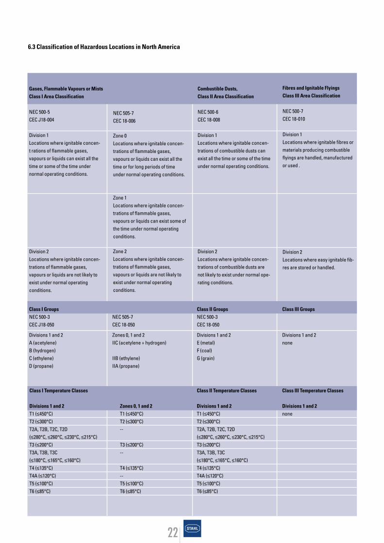
NEC 505-7CEC 18-006
Zone 0Locations where ignitable concen-trations of flammable gases,vapours or liquids can exist all thetime or for long periods of timeunder normal operating conditions.
Zone 1Locations where ignitable concen-trations of flammable gases,vapours or liquids can exist some ofthe time under normal operatingconditions.
Zone 2Locations where ignitable concen-trations of flammable gases,vapours or liquids are not likely toexist under normal operating conditions.
6.3 Classification of Hazardous Locations in North America
Gases, Flammable Vapours or MistsClass I Area Classification
NEC 500-5CEC J18-004
Division 1Locations where ignitable concen-t rations of flammable gases, vapours or liquids can exist all thetime or some of the time under normal operating conditions.
Division 2Locations where ignitable concen-trations of flammable gases, vapours or liquids are not likely toexist under normal operating conditions.
Combustible Dusts,Class II Area Classification
NEC 500-6CEC 18-008
Division 1Locations where ignitable concen-trations of combustible dusts canexist all the time or some of the timeunder normal operating conditions.
Division 2Locations where ignitable concen-trations of combustible dusts arenot likely to exist under normal ope-rating conditions.
Fibres and Ignitable FlyingsClass III Area Classification
NEC 500-7CEC 18-010
Division 1Locations where ignitable fibres ormaterials producing combustibleflyings are handled, manufacturedor used .
Division 2Locations where easy ignitable fib-res are stored or handled.
Class I Groups Class II Groups Class III GroupsNEC 500-3 NEC 505-7 NEC 500-3CEC J18-050 CEC 18-050 CEC 18-050
Divisions 1 and 2 Zones 0, 1 and 2 Divisions 1 and 2 Divisions 1 and 2A (acetylene) IIC (acetylene + hydrogen) E (metal) noneB (hydrogen) F (coal)C (ethylene) IIB (ethylene) G (grain)D (propane) IIA (propane)
Class I Temperature Classes Class II Temperature Classes Class III Temperature Classes
Divisions 1 and 2 Zones 0, 1 and 2 Divisions 1 and 2 Divisions 1 and 2T1 (≤450°C) T1 (≤450°C) T1 (≤450°C) noneT2 (≤300°C) T2 (≤300°C) T2 (≤300°C)T2A, T2B, T2C, T2D -- T2A, T2B, T2C, T2D(≤280°C, ≤260°C, ≤230°C, ≤215°C) (≤280°C, ≤260°C, ≤230°C, ≤215°C)T3 (≤200°C) T3 (≤200°C) T3 (≤200°C)T3A, T3B, T3C -- T3A, T3B, T3C(≤180°C, ≤165°C, ≤160°C) (≤180°C, ≤165°C, ≤160°C)T4 (≤135°C) T4 (≤135°C) T4 (≤135°C)T4A (≤120°C) -- T4A (≤120°C)T5 (≤100°C) T5 (≤100°C) T5 (≤100°C)T6 (≤85°C) T6 (≤85°C) T6 (≤85°C)
23
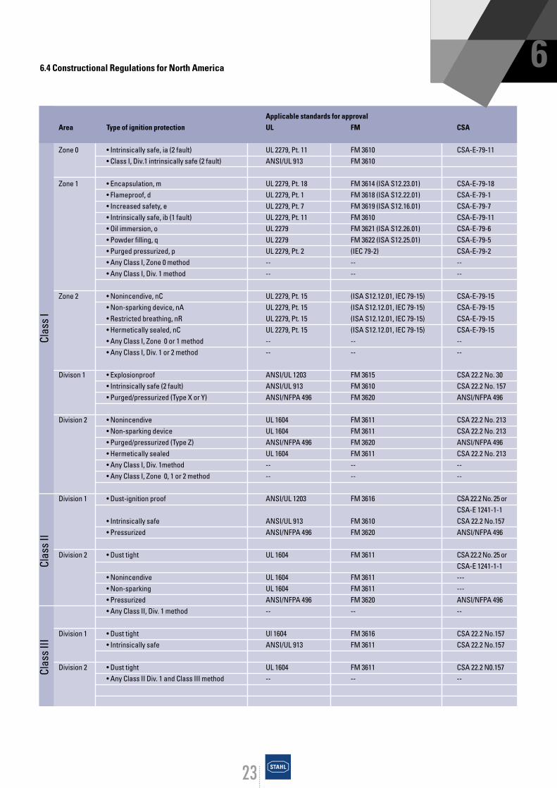
66.4 Constructional Regulations for North America
Clas
s I
Clas
s II
Clas
s III
Applicable standards for approval Area Type of ignition protection UL FM CSA
Zone 0 • Intrinsically safe, ia (2 fault) UL 2279, Pt. 11 FM 3610 CSA-E-79-11• Class I, Div.1 intrinsically safe (2 fault) ANSI/UL 913 FM 3610
Zone 1 • Encapsulation, m UL 2279, Pt. 18 FM 3614 (ISA S12.23.01) CSA-E-79-18• Flameproof, d UL 2279, Pt. 1 FM 3618 (ISA S12.22.01) CSA-E-79-1• Increased safety, e UL 2279, Pt. 7 FM 3619 (ISA S12.16.01) CSA-E-79-7• Intrinsically safe, ib (1 fault) UL 2279, Pt. 11 FM 3610 CSA-E-79-11• Oil immersion, o UL 2279 FM 3621 (ISA S12.26.01) CSA-E-79-6• Powder filling, q UL 2279 FM 3622 (ISA S12.25.01) CSA-E-79-5• Purged pressurized, p UL 2279, Pt. 2 (IEC 79-2) CSA-E-79-2• Any Class I, Zone 0 method -- -- --• Any Class I, Div. 1 method -- -- --
Zone 2 • Nonincendive, nC UL 2279, Pt. 15 (ISA S12.12.01, IEC 79-15) CSA-E-79-15• Non-sparking device, nA UL 2279, Pt. 15 (ISA S12.12.01, IEC 79-15) CSA-E-79-15• Restricted breathing, nR UL 2279, Pt. 15 (ISA S12.12.01, IEC 79-15) CSA-E-79-15• Hermetically sealed, nC UL 2279, Pt. 15 (ISA S12.12.01, IEC 79-15) CSA-E-79-15• Any Class I, Zone 0 or 1 method -- -- --• Any Class I, Div. 1 or 2 method -- -- --
Divison 1 • Explosionproof ANSI/UL 1203 FM 3615 CSA 22.2 No. 30• Intrinsically safe (2 fault) ANSI/UL 913 FM 3610 CSA 22.2 No. 157• Purged/pressurized (Type X or Y) ANSI/NFPA 496 FM 3620 ANSI/NFPA 496
Division 2 • Nonincendive UL 1604 FM 3611 CSA 22.2 No. 213• Non-sparking device UL 1604 FM 3611 CSA 22.2 No. 213• Purged/pressurized (Type Z) ANSI/NFPA 496 FM 3620 ANSI/NFPA 496• Hermetically sealed UL 1604 FM 3611 CSA 22.2 No. 213• Any Class I, Div. 1method -- -- --• Any Class I, Zone 0, 1 or 2 method -- -- --
Division 1 • Dust-ignition proof ANSI/UL 1203 FM 3616 CSA 22.2 No. 25 or CSA-E 1241-1-1
• Intrinsically safe ANSI/UL 913 FM 3610 CSA 22.2 No.157• Pressurized ANSI/NFPA 496 FM 3620 ANSI/NFPA 496
Division 2 • Dust tight UL 1604 FM 3611 CSA 22.2 No. 25 or CSA-E 1241-1-1
• Nonincendive UL 1604 FM 3611 ---• Non-sparking UL 1604 FM 3611 ---• Pressurized ANSI/NFPA 496 FM 3620 ANSI/NFPA 496• Any Class II, Div. 1 method -- -- --
Division 1 • Dust tight Ul 1604 FM 3616 CSA 22.2 No.157• Intrinsically safe ANSI/UL 913 FM 3611 CSA 22.2 No.157
Division 2 • Dust tight UL 1604 FM 3611 CSA 22.2 N0.157• Any Class II Div. 1 and Class III method -- -- --
24
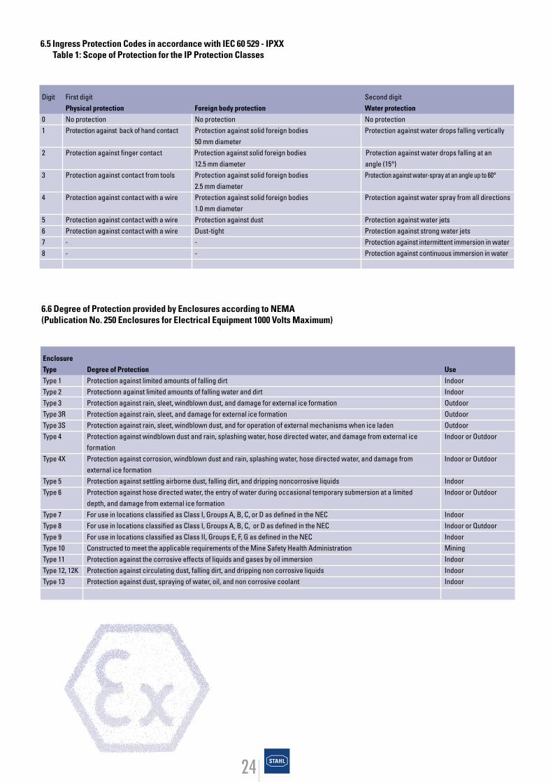
6.5 Ingress Protection Codes in accordance with IEC 60 529 - IPXXTable 1: Scope of Protection for the IP Protection Classes
Digit First digit Second digitPhysical protection Foreign body protection Water protection
0 No protection No protection No protection1 Protection against back of hand contact Protection against solid foreign bodies Protection against water drops falling vertically
50 mm diameter2 Protection against finger contact Protection against solid foreign bodies Protection against water drops falling at an
12.5 mm diameter angle (15°)3 Protection against contact from tools Protection against solid foreign bodies Protection against water-spray at an angle up to 60°
2.5 mm diameter4 Protection against contact with a wire Protection against solid foreign bodies Protection against water spray from all directions
1.0 mm diameter5 Protection against contact with a wire Protection against dust Protection against water jets6 Protection against contact with a wire Dust-tight Protection against strong water jets7 - - Protection against intermittent immersion in water8 - - Protection against continuous immersion in water
6.6 Degree of Protection provided by Enclosures according to NEMA(Publication No. 250 Enclosures for Electrical Equipment 1000 Volts Maximum)
EnclosureType Degree of Protection UseType 1 Protection against limited amounts of falling dirt IndoorType 2 Protectionn against limited amounts of falling water and dirt IndoorType 3 Protection against rain, sleet, windblown dust, and damage for external ice formation OutdoorType 3R Protection against rain, sleet, and damage for external ice formation OutdoorType 3S Protection against rain, sleet, windblown dust, and for operation of external mechanisms when ice laden OutdoorType 4 Protection against windblown dust and rain, splashing water, hose directed water, and damage from external ice Indoor or Outdoor
formationType 4X Protection against corrosion, windblown dust and rain, splashing water, hose directed water, and damage from Indoor or Outdoor
external ice formationType 5 Protection against settling airborne dust, falling dirt, and dripping noncorrosive liquids IndoorType 6 Protection against hose directed water, the entry of water during occasional temporary submersion at a limited Indoor or Outdoor
depth, and damage from external ice formationType 7 For use in locations classified as Class I, Groups A, B, C, or D as defined in the NEC IndoorType 8 For use in locations classified as Class I, Groups A, B, C, or D as defined in the NEC Indoor or QutdoorType 9 For use in locations classified as Class II, Groups E, F, G as defined in the NEC IndoorType 10 Constructed to meet the applicable requirements of the Mine Safety Health Administration MiningType 11 Protection against the corrosive effects of liquids and gases by oil immersion IndoorType 12, 12K Protection against circulating dust, falling dirt, and dripping non corrosive liquids IndoorType 13 Protection against dust, spraying of water, oil, and non corrosive coolant Indoor
25
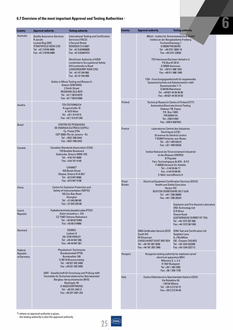
6.7 Overview of the most important Approval and Testing Authorities *
Country Approval authority Testing authority
Quality Assurance Services International Testing and Certification R Jacobi Services (ITACS)Locked Bag 2032 2 Second StreetSTRATHFIELD NSW 2135 BOWDEN S A 5007Tel: +61 2 9746 4900 Tel: +61 8 83468680Fax: +61 2 9746 8460 Fax: +61 8 83467072
WorkCover Authority of NSWLondonderry Occupational Safety 919 Londonderry RoadLONDONDERRY NSW 2753Tel: +61 47 244 900Fax: +61 47 244 999
6
*) where no approval authority is given, the testing authority is also the approval authority
Safety in Mines Testing and Research Station (SIMTARS)
2 Smith StreetREDBANK QLD 4075Tel: +61 7 3810 6370Fax: +61 7 3810 6366
TÜV ÖSTERREICHKrugerstraße 16
A 1015 WienTel: +43 1 514 07 0
Fax: +43 1 514 07 240
CENTRO DE PESQUISASDE ENERGIA ELETRICA (CEPEL)
Cx. Postal 2754CEP 20001 Rio de Janeiro - RJ
Tel: +5521 598 2442Fax: +5521 598 2443
Canadian Standards Association (CSA)178 Rexdale Boulevard
Etobicoke, Ontario M9W 1R3Tel: +416 747 4000Fax: +416 747 4149
CANMET555 Booth Street
Ottawa, Ontario K1A 0G1Tel: +613 947 6580Fax: +613 947 4198
Centre for Explosion Protection andSafety of Instrumentation (NEPSI)
103 Cao Bao RoadShanghai
Tel: +21 643 86180Fax: +21 643 335 66
Fyzikalne technicky zkusebni ustav (FTZU)Statni zkusebna c. 210
CZ 71607 Ostrava-RadvaniceTel: +42 69 6215484Fax: +42 69 214860
DEMKOLyskaer 8
DK-2730 HERLEVTel: +45 44 947 266Fax: +45 44 947 261
Physikalisch-Technische Bundesanstalt (PTB)
Bundesallee 100D 38116 Braunschweig
Tel: +49 531 592 3400Fax: +49 531 592 3405
DMT - Gesellschaft für Forschung und Prüfung mbHFachstelle für Sicherheit elektrischer Betriebsmttel
Bergbau-Versuchsstrecke (BVS)Beylingstr. 65
D 44329 DORTMUNDTel: +49 231 2491 0
Fax: +49 231 2491 224
IBExU - Institut für Sicherheitstechnik GmbHInstitut an der Bergakademie Freiberg
Fuchsmühlenweg 7D 09599 FREIBERG
Tel: +49 3731 3805 19Fax: +49 3731 23650
TÜV Hannover/Sachsen-Anhalt e.V.P.O.Box 81 05 51
D 30505 HannoverTel: +49 511 986 1552Fax: +49 511 986 1590
FSA - Forschungsgesellschaft für angewandte Systemsicherheit und Arbeitsmedizin mbH
Dynamostraße 7-11D 68165 Mannheim
Tel: +49 621 44 56 36 06Fax: +49 621 44 56 34 02
Technical Research Centre of Finland (VTT)Automation/Electrotechnical Testing
Otakaari 7B, EspooP.O. Box 13051FIN 02044 Vtt
Tel: +358 9 4561Fax: +358 9 4567042
Laboratoires Central des IndustriesElectriques (LCIE)
33 avenue du Général LeclercF 92260 Fontenay-aux-Roses
Tel: +33 1 409 55519Fax: +33 1 409 55520
Institut National de l’Environnement Industriel et des Risques (INERIS)
B PiquetteParc Technologique ALATA - B.P.2
F-60550 Verneuil-En-HalatteTel: + 3 44 55 66 77Fax: +3 44 55 66 99
E-Mail: [email protected]
Electrical Equipment Certification Services (EECS)Health and Safety Executive
Harpur HillBUXTON DERBYSHIRE SK17 9JN
Tel: +44 1 298 28000Fax: +44 1 298 28244
Explosion and Fire Hazards LaboratoryERA Technology LtdG R OliverCleeve Road LEATHERHEAD SURREY KT 7SATel: +44 1372 367 000Fax: +44 1372 367 099
SIRA Certification Service (SCS) SIRA Test and Certification LtdSouth Hill Saighton LaneM Shearman A J McMillanCHISELHURST KENT BR7 5EH GB - Chester CH3 6EGTel: +44 181 467 2636 Tel: +44 1244 332200Fax: +44 181 295 1990 Fax: +44 1244 332112
Hungarian testing authority for explosion-proofelectrical apparatus (BKI)
Mikoviny S. u. 2-4H 1037 Budapest
Tel: +36 1 168 7260Fax: +36 1 250 1720
Centro Elettrotecnico Sperimentale Italiano (CESI)Via Rubattino 54I 20134 Milano
Tel: +39 2 212 53 72Fax: +39 2 212 54 40
Australia
Austria
Brazil
Canada
China
CzechRepublic
Denmark
FederalRepublicof Germany
Finland
France
Great Britain
Hungary
Italy
Country Approval authority Testing authority

26
The Technical Institution of Industrial Safety (TIIS)1-4-6 Umezono Kiyose
Tokyo 204Tel: +81 424 91 4514Fax: +81 424 95 2461
Service de l´Energie de l´Etat LuxembourgeoisB.P. 10
L 2010 LuxembourgTel: +352 46 97 48Fax: +352 22 25 24
KEMAPostbus 9035
NL 6800 ET ARNHEMTel: +31 26 3 56 34 28Fax: +31 26 3 51 01 78
NEMKOP O Box 73 Blindern
N 0314 OSLOTel: +47 22 960330Fax: +47 22 698636
Glowny Institut GornictwaKopalnia Doswiadczalna ”BARBARA”ul. Podleska 72, skrytka pocztowa 72
PL 43-190 MikolowTel: +58 2028 024 9Fax: +58 2028 745
Korea Industrial Safety Corp. (KISCO)34-4 Kusa-dong, Poopyoung-gu
Inchon 403-120The Republic of Korea
Tel: +82 32 5100 865Fax: +82 32 518 6483-4
South African Bureau of Standards (SABS)1 Dr. Lategan Road, Groenkloof, Pretoria
Private Bag X191Pretoria 0001
Tel: +12 428 7911Fax: +12 344 1568
INSEMEX PETROSANI Equipment Ex. Certification Service
Str. Gen. Vasile Milea nr.32-34Cod 2675 Petrosani.Tel: +4 054 541 621Fax: +4 054 232 277
Test centre for explosion-proof electrical apparatus (VNIIEF)formerly Arzamas 16
Prospect Mira, 37607190 Sarov
Tel: +831 30 45669Fax: +831 30 45530
Elektrotechnicky vyskumny a projektovy ustav (EVPU)
Statna skusobna SKTC 101SK 01851 Nova Dubnica
Tel: +Fax: +
Mr Igor LikarSlovenian Institute of Quality and Metrology (SIQ)
Trazaska cesta 2 SL-1000 Ljubljana
Tel: +386 61 177 8100Fax: +386 61 177 8444
Laboratorio Official Jose Maria Madariaga (LOM)Calle Alenzaa 1-2E 28003 Madrid
Tel: +34 1 442 13 66Fax: +34 1 441 99 33
Country Approval authority Testing authority
Swedish National Testing and Research Institute (SP)
Brinellgatan 4Box 857
S-501 15 BORASTel: +46 33 16 5000Fax: +46 33 13 5502
Eidgenössisches Schweizerischer ElektrotechnischerStarkstrominspektorat (ESTI) Verein (SEV)Luppmenstraße 1 Luppmenstraße 1CH 8320 FEHRALTORF CH 8320 FEHRALTORFTel: +41 1 956 12 12 Tel: +41 1 956 11 11Fax: +41 1 956 12 22 Fax: +41 1 956 11 12
Test and certification centre forexplosion-proof and flame-proofelectrical apparatus (ISZ VE)
ul. Gvardeiskoi Divisii 17340052 Donezk
Tel: +Fax: +
Underwriters Laboratories Inc. (UL)333 Pfingsten Road
Northbrook, IL 60062-2096Tel: +847 272 8800Fax: +847 272 8129
Factory Mutual Research Corporation (FM)1151 Boston-Providence Turnpike
P.O. Box 9102Tel: +781 255 4840Fax: +781 762 9375
SAVEZNO MINISTARSTVO ZA RAZVOJ,NAUKU i ZIVOTNU SREDINU
SAVEZNI ZAVOD ZASTANDARDIZACIJU (SZS)
Federal Ministry for Development, Science and Environment
Federal Institution for StandardizationKneza Milosa 20
YU BeogradTel: +11 681 999Fax: +235 10 36
Japan
Luxemburg
Netherlands
Norway
Poland
Republic Korea
Rebublic ofSouth Africa
Romania
Russia
Slovakia
Slovenia
Spain
Sweden
Switzerland
Ukraine
USA
Yugoslavia
Country Approval authority Testing authority

27
28
7. Literature
Directive 94/9/EU of the European Parliament and the councilof 23 March 1994 on the approximation of the laws of themember states concerning equipment and protective sytemsintended for use in potentially explosive atmos-pheresOfficial Journal of the European Communities
Second Order to the equipment safety law and amendmentsto equipment safety law safety legislation dated 12.12.1996,Federal Gazette 1996 Part I No. 65
Bulletin of the new edition of the Order on electrical apparatus in potentially explosive areas dated 13.12.1996,Federal Gazette 1996 Part I No. 65
Explosion protection of electrical apparatus; order on electricalapparatus in potentially explosive areas (ElexV), commentaryand collected texts] Erich Schmidt Verlag, Berlin
Code of practice for explosion protection (Ex-RL) - code ofpractice for the avoidance of the dangers of potentiallyexplosive atmospheres with collected examples (ZH1/10)BG-Chemie (1998)Werbe-Druck Winter, Sandhausen
K. Nabert and G. Schön: Safety ratings of flammable gases and vapoursDeutscher Eichverlag, Braunschweig
Flammability and explosion parameters for dustBerufsgenossenschaftliches Institut für Arbeitssicherheitund Bergbau-Versuchsstrecke (1987)Erich Schmidt Verlag, Bielefeld
D. Beermann, B. Günther, A. Schimmele: Intrinsic safety inexplosion-proof measurement and control systems - func-tions, selections, installation, operation.VDE-Verlag GmbH, Berlin and Offenbach
H. Greiner: Explosion protection for three-phase gearedmotors Druckschrift SD 393, Eberhard Bauer Motoren, Esslingen 1993
G. Lüttgens, M. Glor: Understanding and safely controllingelectrostatic charges, Expert Verlag, Ehningen (1988)
DIN VDE 0170/0171 Part 1 ff.(EN 50 014 ff.) Electrical apparatus for potentially explosive atmospheresVDE-Verlag GmbH, Berlin
DIN VDE 0470 Part 1 (EN 60 529) IP-Schutzarten; Specificationfor degrees of protection provided by enclosures (IP code)VDE-Verlag GmbH, Berlin
DIN VDE 0165/02.91 Installation of electrical apparatus inpotentially explosive areasVDE-Verlag GmbH, Berlin
DIN EN 60 079-14 VDE 0165 Part 1:1998-08Electrical apparatus in areas prone to gas explosionsElectrical installations in hazardous areasVDE-Verlag GmbH, Berlin
DIN VDE 0105 Part 9: 1986-05 Operation of high-voltageequipment - supplementary specifications for potentiallyexplosive areasVDE-Verlag GmbH, Berlin
Dust explosion protection on machines and apparatus, ISSAPrevention Series No. 2033(G), Mannheim 1998
NFPA 70 - 1996 National Electrical Code, 1996 editionNational Fire Protection Association, Quincy, MA, USA
NFPA 70 - 1999 National Electrical Code, 1999 editionNational Fire Protection Association, Quincy, MA, USA
1998 Canadian Electrical Code, 18th editionCanadian Standards Association, Etobicoke, ON, Canada
1996 National Electrical Code Review and Application GuideKillark Electric Manufacturing Company, St. Loius, MO, USA
1998 Canadian Electrical Code Review and Application GuideHubbell Canada Inc. - Killark, Pickering, ON, Canada

29
8. Index
Associated electrical apparatus 14, 15ATEX 100a 8ATEX 118a 11
Basic health and safety requirements 8BVS/DMT (Bergbauversuchsstrecke Dortmund) 25
Cable system 16, 17Categories (equipment categories) 11CEC (Canadian Electrical Code) 18, 22CE marking 10CENELEC 8Certificate of conformity 8, 9Class 18, 22Components 9Conduit system 17Construction regulations EUROPE 8
NORTH AMERICA 23
Danger Class 6Declaration of conformity 9, 10Degree of protection (IP code) 24Division 18, 22Dust 11, 18Dust explosion protection 8
EC Directive 8, 9Electrical apparatus 9EMC Directive 10EN (European Standard) 8, 20Equipment 9Equipment category 11Equipment groupExplosion 6, 11Explosion limits 6ExVo 10
Fault safety, sinle/double 15Flame proof enclosure 14Flash point 6
Galvanic isolation 15Gas group 11, 21German Technical Regulations for Flammable Liquids (TRbF) 6Group 18, 22
IEC (International Electrotechnical Commission) 8, 20Ignition temperature 12, 21Increased safety 14Installation systems 16Intrinsic safety 14
Maintenance 16, 17Marking 10, 19MESG (maximum experimental safe gap) 11MIC (minimum ignition current) 11Minimum ignition energy 14
NEC (National Electrical Code) 18, 22NEMA (National Electrical Manufacturing Association) 18, 24
Potentially explosive area, hazardous location 9, 11, 16Potentially explosive atmosphere 9, 11Primary explosion protection 7Protective systems 9PTB (Physikalisch-Technische Bundesanstalt) 10, 25
Quality assurance 10
Routine testing 16
Safety barrier 15Safety factor 14Secondary explosion protection 7Sources of ignition 6, 7Special protection 12Safety caracteristic 21Surface temperature 12, 18
Testing authority 25, 26Temperature class 11, 12, 18, 21, 22Type examination certificate, EC 10Types of protection 12
Zener diode 15Zones 11, 12, 18, 22
30
Federal Republic of GermanyR. STAHL SCHALTGERÄTE GMBHGrusonstr. 5522113 HamburgTel. 040/736054-0Fax 040/73605454
R. STAHL SCHALTGERÄTE GMBHDeutz-Mülheimer-Str. 25451063 KölnP.O.Box 80100651010 KölnTel. 0221//9625690Fax 0221/96256925
R. STAHL SCHALTGERÄTE GMBHArmstrongstr. 1504509 Glesien / LeipzigTel. 034207/49011, 49013Fax 034207/49029
R. STAHL SCHALTGERÄTE GMBHUlmer Str. 231-23970327 StuttgartTel. 0711/407041-0Fax 0711/4201887
ArgentinaNORRI S.R.L.Prilidiano Pueyrredon 679RA-1640 Martinez (Buenos Aires)Tel. 01/6129101/6112831Fax 01/7982655
AustraliaCLIPSAL STAHL EX PTY LTD12 Short Street, BankstownAUS-New South Wales 2200Tel. 02/97906719Fax 02/97905949
AustriaROBERT NISSL GES.M.B.H.Jochen-Rindt-Str. 41A-1230 WienTel. 01/6163929Fax 01/616392922
BelgiumR. STAHL N.V. Ind. Terrein HoogveldWissenstraat 17B-9200 DendermondeTel. 052/211351Fax 052/211347
BrazilINSTRUMENTOS LINCE LTDA.Rua Luiz Ferreira, 84BR-21042-210 Rio de Janeiro-RJTel. 021/5732344Fax 021/5615326
ChileDESIMAT LTDA.6 Oriente 38510024 Correo 4RCH-Vina del MarTel. 032/690815Fax 032/690816
P.R. ChinaCLIPSAL CHINA LTD.Unit 412, Level 4, North Office TowerBeijing Kerry Centre,No. 1 Guang Hua Road,Chao Yang District,RC-100020 BeijingTel. 010/85298168Fax 010/85298166
CLIPSAL CHINA LTD.Shanghai OfficeSuite 526, American International Centre1376 Nanjing Road WestRC-Shanghai 200040Tel. 021/62470183Fax 021/62477130
CLIPSAL CHINA LTD.15/F, Office Tower Shun Hing Square Diwang Commercial Centre333 Shen Nan Dong RoadRC-Shenzhen 518008Tel. 0755/2461122Fax 0755/2461778
ColumbiaELECTRO CELDAS LTDA.Carrera 64, No. 26A-76 SURP.O. Box 38686CO-BogotaTel. 01/2615262Fax 01/4145528
CroatiaTEHMAR d.o.o.Kralja Zvonimira 91HR-21000 SplitTel. 021/511094Fax 021/519970
Czech RepublicEX-TECHNIK spol. s.r.o.Na Peconce 1903/21CS-710 00 OstravaTel. 069/6242548Fax 069/6242551
DenmarkMAX FODGAARD A/SHeimdalsgade 33DK-2200 Kopenhagen - N.Tel. 535851700Fax 535853110
EgyptEAGLE CO. FOR ENGINEERING SERVICES LTD.74, Abdel El-Salam Aref Str., GlimET-AlexandriaTel. 03/5807079Fax 03/5801880
EstoniaTALGER-ELEKTROTECHNICS AS15, Laki Str. EE0006TallinnTel. 02/6563618Fax 02/6563617
FinlandEX-TEKNIIKKA OYSörn. Rantatie 27SF-00500 HelsinkiTel. 09/738144Fax 09/738706
FranceETS STAHL S.A.104-106 rue de MontignyF-95100 ArgenteuilTel. 01/39985050Fax 01/34111818
Great BritainR. STAHL LTD.Stahl House,43 Elmdon Trading Estate Bickenhill LaneGB-Birmingham B37 7HETel. 0121/7676400Fax 0121/7676490
GreeceDYAS CONTROLSThomas Sapounas & Co.2 Neromilou Str. GR-13671 Chamomilos Acharnes / AthenTel. 01/2406006Fax 01/2406007
Hong KongCLIPSAL ASIA LTD.3/F., Wyler Centre,200 Tai Lin Pai RoadKwai Chung, N.T.Tel. 24870261Fax 24805865
HungaryMILEIPARI-ELEKTRO NAGYKERESKEDESX., Mádi u. 52H-1104 BudapestTel. 01/2615535Fax 01/2615535
IndiaBALIGA-STAHL PVT. LTD.11, Arcot RoadLakshmi Nagar, PorurIND-Chennai 600 116Tel. 044/4826674Fax 044/4826674
IndonesiaP.T. MUSTIKA STAHLJl. Griya Agung No. 81 Blok 0/49Griya Inti Sentosa, Sunter AgungRI-Jakarta 14350Tel. 021/6450574Fax 021/6404249
ItalyR. STAHL S.R.L.LeiviI-16040 S. Colombano (Ge)Tel. 00185/358391/2Fax 00185/358219
Via O. Guerrini 14I-20133 MilanoTel. 002/2665962Fax 002/2365446
JapanR. STAHL K.K.Parale Mitsui Bldg. 17F8 Higashida-cho, Kawasaki-kuKawasaki, KanagawaJ-210 JapanTel. 044/2001611Fax 044/2001615
*YAMATAKE CO. LTD.2-12-19 ShibuyaJ-Tokyo 150International SectionTelex 22902* for products in our I.S. electronics componentsdivision
KuwaitEBOMAC - Electrical Boards Manufacturing Co.P.O. Box 25428KWT-Safat 13115Tel. 4727550, 4727466Fax 4765059, 4763016
SUBSIDIARIES OF R. STAHL SCHALTGERÄTE GMBH
31
LatviaBALTIK ELEKTRO - Electro wholesaleKengaraga Str. 10LV-1063 Riga Tel. 02/263576Fax 7188862
LithuaniaEB-ELEKTROBALTJonavos 62a3000 KaunasLithuaniaTel. 07/228386Fax 07/209857
Makedonia NIKEXul Vasko Karangelevski 25/39SkopjeTel. 091/163322Fax 091/163322
MalaysiaINTERSTATE-STAHL SDN. BHD.No. 5 & 7, Jalan PJS 11/20Bandar Sunway46150 Petaling JayaMAL-Selangor Darul EhsanTel. 03/7366188Fax 03/7377688, 7387688
NetherlandsELECTROMACH B.V.Hamerstraat 10P.O. Box 175NL-7550 AD HengeloTel. 074/2472472Fax 074/2435925
New ZealandELECTROPARP.O. Box 58623GreenmountNZ-Auckland 1701Tel. 09/2742000Fax 09/2742001
NorwaySTAHL-SYBERG A/SStromsveien 346N-1081 OsloTel. 022/906000Fax 022/906020
OmanALI TRADING CO.P.O. Box 51064Mina Al-FahalTel. 701576, 708448Fax 705629
PakistanCLIPSAL PAKISTAN (PVT.) LTD.188-R, Block 2, P.E.C.H.S.PA-KarachiTel. 021/4533326Fax 021/4531345
PolandASE-Automatic Systems Engineeringul. Narwicka 6PL-80557 GdanskTel. 058/3432425Fax 058/3464344
PortugalFERROMETAL LTDA.Rua Joaquim Antonio de Aguiar 45 R/CP-1000 Lisboa 1Tel. 01/3813060Fax 01/3813079
QatarDOHA MOTORS & TRADING CO.Al-Wakra RoadQA-DohaTel. 651441Fax 650925
RomaniaING. MO.- UNGER SEFAG LTDRezonantei 1-3, Bl. 15-16, Scara 4Etaj 1, Ap 49, Cod. 75513, Sector 4R-BucharestTel. 01/13373559Fax 01/13370859
RussiaINTERPROMPRIBORVekovaya Str. 21109544 MoskauTel. 095/2782512Fax 095/2780423
Saudi ArabiaA. ABUNAYYAN ELECTRIC CORP.P.O. Box 321SAR-Riyadh 11411Tel. 01/4779111Fax 01/4793312
SingaporeR. STAHL PTE LTD.25 International Business Park#03-65/73 German CentreSGP-2260 SingaporeTel. 5627900Fax 5627919
SlovakiaEX-TECHNIK SLOVAKIA S.S.R.O.Geologicka 21SK-821 06 BratislavaTel. 07/45524607Fax 07/45520095
SloveniaSYNATEC d.o.o.Vojkova 8SLO-65280 IdrijaTel. 065/73351, 72211Fax 065/72351, 71703
Republic of South AfricaESACO PTY. LTD.P.O. Box 3095RZA-1610 EdenvaleTel. 011/4444087Fax 011/4447136
SpainINDUSTRIAS STAHL S.A.Aragoneses, 2 Acceso 10Poligono IndustrialE-28100 Alcobendas (Madrid)Tel. 091/6615500Fax 091/6614999
SwedenR. STAHL SVENSKA ABBagspännarvägan 14S-17568 JärfällaTel. 08/389100, 389180Fax 08/389198
SwitzerlandSTAHL-FRIBOS AGBänihübelCH-5070 FrickTel. 062/8654060Fax 062/8654080
TaiwanWAN JIUIN HSING ENTERPRISE CO. LTD.11F-1, No. 178, Sec. 4, Cheng Te Rd.TAI-TaipeiTel. 02/8822211, 8830005, 8830006Fax 02/8817562, 8812004
ThailandC.K. ELECTECH CO. LTD.31/14 Dhamrongruk Rd.PomprabT-Bangkok 10100Tel. 02/2815607Fax 02/2803663
TurkeyKAS PAZARLAMA A.S.Ahmet Rasim Sokak No. 13/1-2TR-06550 Cankaya / AnkaraTel. 0312/4414335Fax 0312/4414336
USAR. STAHL INC. Corporate Hdq. and Manufacturing45 Northwestern DriveUSA-Salem, New Hampshire 03079-4809Tel. 603/8709500Fax 603/8709290
KILLARK-STAHL INC.P.O. Box 5325USA-St. Louis, Mo. 63115Tel. 314/5310460Fax 314/5317164
VenezuelaTEX C.A.Av. Sucre, Centro Torre BoyacáTorre Centro, Piso 2, Oficina 134Los Dos Caminos YV CaracasTel. 02/2868582Fax 02/2868947
VietnamA.T. SECURITY EQUIPMENT COMPANY51 Quang Trung Str.HanoiTel. 04/8228489Fax 04/8225102
YugoslaviaMINEL-KEYINGDositejeva 24YU-23300 KikindaTel. 0230/34519Fax 0230/23479
As at: November 1998
Subsidiaries
AustriaR. Stahl Ges.m.b.H.Linzer Straße 29 aA - 4221 SteyreggTel. ..43 732 / 64 11 11 0Fax ..43 732 / 64 11 11 33e-mail [email protected]
BrazilStahl Equipamentos Industriais Ltda.Estrada Do Gramado, No. 701 - Bairro GramadoCEP 06833-080 Embú - SPBrazilTel. ..55 11 / 7961 0266Fax ..55 11 / 494 2732e-mail [email protected]
FranceEts. Stahl S.A.104-106, rue de MontignyF- 95100 ArgenteuilTel. ..33 1 / 39 98 50 60Fax ..33 1 / 34 11 18 18e-mail [email protected]
Great BritainR. STAHL LTD.Stahl House43 Elmdon Trading EstateBickenhill LaneGB - Birmingham B37 7HETel. ..44 121 / 767 64 00Fax ..44 121 / 767 64 80e-mail [email protected]
ItalyR. STAHL S.R.L.Loc. Coggozzale, LeiviI - 16040 S. Colombano (GE)Tel. ..390 185 / 35 83 91Fax ..390 185 / 35 82 19e-mail [email protected]
Netherlands(Benelux)R. Stahl B.V.TransporttechniekP.O.Box 96 99Pieter Goedkoopweg 34NL - 2031 EL HaarlemTel. ..31 23 / 5 31 20 03Tlx. 41157Fax. ..31 23 / 5 31 18 25e-mail [email protected]
PortugalFerrometal Lda.Rua J. Antonio de Aguiar, 45-R/CP - 1000 Lissabon - 1Tel. ..351 1 / 381 30 60Tlx. 12225Fax ..351 1 / 381 30 79e-mail [email protected]
SingaporeR. Stahl Pte. LTD.25 International Business Park# 03-65/73 German CentreSingapore 609916Tel. ..65 / 56 27 90 0Fax ..65 / 56 27 90 9e-mail [email protected]
SpainINDUSTRIAS STAHL S.A.Aragoneses 2 - Acceso 10Poligono IndustrialSP - 28100 Alcobendas (Madrid)Tel. ..34 91 / 661 55 00Fax ..34 91 / 661 27 83e-mail [email protected]
SwitzerlandSTAHL-FRIBOS AGFördertechnikBänihübelCH - 5070 FrickTel. ..0041 62 / 865 40 60Fax ..0041 62 / 865 40 80e-mail [email protected]
USAR. Stahl, Inc.Material Handling DivisionP.O. Box 40609Charleston, SC 29423-0609USATel. ..1 843 / 767 1951Fax ..1 843 / 767 4366e-mail [email protected]
Branches
DüsseldorfR. STAHL FÖRDERTECHNIK GMBHNiederlassung DüsseldorfEichsfelder Str. 440595 Düsseldorf / HellerhofTel. 0211 / 970 04-0Fax 0211 / 970 04-50e-mail [email protected]
HannoverR. STAHL FÖRDERTECHNIK GMBHNiederlassung HannoverVarrelheidering 1130659 HannoverTel. 0511 / 90198-0Fax 0511 / 90198-88e-mail [email protected]
MunichR. STAHL FÖRDERTECHNIK GMBHNiederlassung MünchenCarl-von-Linde-Straße 1185748 Garching-HochbrückTel. 089 / 329542-0Fax. 089 / 329542-31e-mail [email protected]
StuttgartR. STAHL FÖRDERTECHNIK GMBHNiederlassung StuttgartUlmerstr. 23970327 StuttgartTel. 0711 / 4094-411Fax 0711 / 4094-365e-mail [email protected]
SUBSIDIARIES of R. STAHL FÖRDERTECHNIK GMBH
32

33
2
34
NotesNotes

35
2

R. STAHL SCHALTGERÄTE GMBHP.O.Box 1263 · D-74642 Künzelsau · Fax 0 79 40/17-377E-Mail: [email protected] · Internet: http://www.stahl.deR. STAHL FÖRDERTECHNIK GMBHP.O.Box 1161 · D-74641 Künzelsau · Fax 0 79 40/5 56 65E-mail: [email protected] · Internet: http://www.stahl.de S-
SD-0
2-E-
07/9
9 · P
rinte
d in
the
Fede
ral R
epub
lic o
f Ger
man
y · s
cannneerr gg
mmbbhh