Embed Size (px)
Citation preview

Installation Guide
BasicPlus2 WT-DMRoom thermostat

1 Installation Steps
2 Wiring
Installation Guide
WT-DM Installation Instruction
Danfoss Heating Solutions 2
The User Guide can be downloaded from: heating.danfoss.com.
1. Installation must be done by an authorised electrician.2. The room thermostat should be installed at approx. 1.5 m
above �oor and where the e�ects of sunlight, draught orother heat sources (eg. TV's) are avoided. See �g.1.
3. First of all, carefully remove the cover. See �g.2.4. Connect the wire before mounting the back plate to the
wall box using the enclosed screws. Then mount the cover to the back plate. See �g.3.
1. Dimensions, see �g.4.2. Wiring diagram,see �g.5. (S1,S2:�oor sensor terminals;A+,B-: Modbus communication terminals).3. WT-DM is often used with Danfoss TWA actuator. Depending
on the conditions of power location and actuator type (NC or
GB

1. When power supply location is close to room thermostat: type,see �g.6.type,see �g.7.
type,see �g.8.type,see �g.9.
NO), the wiring between room thermostat and actuator is dif-ferent.Follow the illustrations to complete the wiring:
3

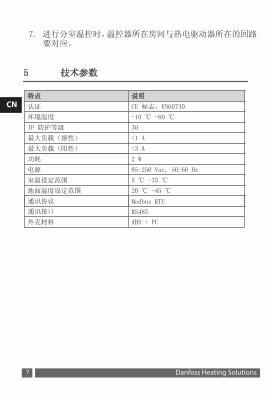
Technical Specifications
Communication protocol Modbus RTU
Communication interface RS485
4

DM
CN
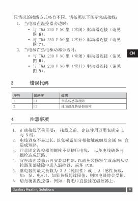
安装指南
WT-DM 安装说明书
必须由经过专业培训合格的电工进行安装。1.
2. 室内温控器应当安装在地面上方大约1.5米处,并且避免受到日光、气流或者其他热源(例如:电视)的影响。请见图1。
在将背板固定至暗线箱之前,使用随附的螺钉连接导线,然后将盖子安装至背板。请见图
5
CN
6
CN
通讯协议 Modbus RTU
通讯接口 RS485
7
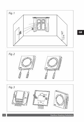
Fig. 1
1.5 m
Fig. 2
Fig. 3
Danfoss Heating Solutions8

Fig. 486
.0
86.0 24.516.0
62.3
46.2
Fig. 5S2S1B-A+N
NCNO
L
230 V ~
Modbus Communication
Floor Sensor
Fig. 6
N230 V ~
L
TWA230V
NC
WT-DM
L NO NC N A+ B- S1 S2
Danfoss Heating Solutions 9

Danfoss Heating Solutions10
Installation Guide BasicPlus2 WT-DM
Fig. 7
N230 V ~
L
TWA230VNO
L NO NC N A+ B- S1 S2
WT-DM
Fig. 8
N230 V ~
L
TWA230V
NC
L NO NC N A+ B- S1 S2
WT-DM
Fig. 9
N230 V ~
L
TWA230VNO
L NO NC N A+ B- S1 S2
WT-DM

Ulvehavevej 61Floor Heating Hydronics
VICUM12P Produced by Danfoss Floor Heating Hydronics 05/2015