Embed Size (px)
Citation preview

DUKE UNIVERSITY
APRIL 28, 2015
Basic Wire Bonding Theory
Parameter Development
Practical Applications
Presented by Kyle Huth of K H Sales

� Definitions and Terminology
� Materials
� Bonding Process
� Parameter Guidelines
� Small Group Hands On Application
� Homework

� Wire BondThe process of intermetalically connecting Au or Al wire or ribbon to a microelectronic
device
� UltrasonicHigh frequency motion used to “scrub” the wire or ribbon into the desired surface to create
a wire bond
� ThermocompressionA combination of heat and pressure used to force the wire or ribbon into the desired
surface to create a wire bond
� ThermosonicCombination of both Ultrasonic and Thermocompression bonding

� TransducerThe ferrite horn that transfers the ultrasonic
oscillation from the crystal oscillators to the bonding tool
� Wire ClampsMechanical method for gripping the wire for
terminations and wire feed
� Bonding ToolWedge or Capillary used to attach the wire or ribbon
at the desired site
� Wire DespoolerDevice which holds the spool and helps regulate the
back tension in the wire
� ManipulatorHand Controller to position the bond tool at the
desired site to place the bond
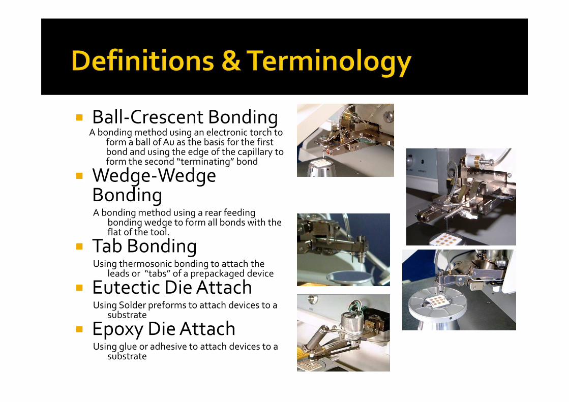
� Ball-Crescent BondingA bonding method using an electronic torch to
form a ball of Au as the basis for the first bond and using the edge of the capillary to form the second “terminating” bond
� Wedge-Wedge BondingA bonding method using a rear feeding
bonding wedge to form all bonds with the flat of the tool.
� Tab BondingUsing thermosonic bonding to attach the
leads or “tabs” of a prepackaged device
� Eutectic Die AttachUsing Solder preforms to attach devices to a
substrate
� Epoxy Die AttachUsing glue or adhesive to attach devices to a
substrate

� ForceThe contact pressure created by the downward motion of the bond tool, capturing and
compressing the wire against the desired surface
� Stage HeatHeat applied to the assembly held in the work holder to assist in the bonding process
� Tool HeatHeat applied to the bonding tool thru the radient heater coil to precondition the Au wire
and soften its grain structure
� Ultrasonic PowerThe amplitude of the Ultrasonic motion
� Ultrasonic TimeThe duration of the Ultrasonic motion measured in milliseconds

� CapillaryBonding Tool usually made of ceramic
� Ball BondThe compression of the formed ball to make the first bond
forming a bell shape
� Free Air BallThe ball formed by the torch below the tool prior to bonding
� Inside ChamferThe inside dimensions of the capillary which concentrates the
forces used to form the bond
� Crescent BondTermination bond formed by the outside radius of the capillary

� WedgeBonding tool with rear feed to position wire directly under the
active area of the tool
� ToeThe front most part of the bond formed by the front radius of the
wedge
� FootThe portion of the bond created by the largest contact area of the
tool. This is where your bond strength is.
� HeelThe portion of the bond formed by the back radius of the wedge.
This is the weakest area of the bond
� StitchMaking two or more connected loops to connect parallel circuits
� Deep AccessMethod used to bond inside walled packages, using a hollow
centerline tool

� Bond StrengthThe amount of force needed to cause a completed bond to fail
� Bond LiftThe deformed wire at the bond site separates from the material it was to be attached to
� Metallization LiftThe bond adheres to the targeted area but the metallization under the bond separates
from the device
� CrateringThe bond sticks, appears to be good but the crystal structure under the bond collapses and
causes an open area under the bond
� Bond PeelHeel of the bond starts to lift but does not fully separate from the bond

� Wire BreakA break in the midspan
of a bonded wire providing the break point is above the minimum standard for that size and type of material is the best failure you could get. It is an ideal strength bond pull.

� Eutectic Die AttachThe attachment of discrete devices into an
assembly using solder usually in preforms
� Epoxy Die AttachThe attachment of discrete devices to an
assembly making use of glue or adhesive
materials

� GaAsRelatively delicate crystal used for high speed and frequencies, Very thin (4-8 mils) Subject
to fracturing under either excessive force or ultrasonics “Low and Slow”
� SiliconRobust crystal used for less critical applications Higher threshold for force and ultrasonics
� Chip CapacitorsCeramic based components. Very robust, but often dirty
� ResistorsUsually ceramic based with thin film surfaces, subject to metallization lifts

� CeramicAlumina, typical substrate used for insulating properties, circuits usually have Au top layer
for bonding
� DuroidUsually Cu impregnated polymer used for its dielectric range. Very heat sensitive and
reactive to ultrasonics “high and hard”
� KovarMetal alloy, always plated, simple to bond due to stability under almost all conditions
� FR4Standard PCB material, used for Chip on Board. Handles some heat and ultrasonics but
drawback is often its large dimensions

The bonding process is the following sources of
energy combined to cause the material from
the wire or ribbon to join to the target
material in an intermetallic joint.
Force
Tool Heat
Stage Heat
Ultrasonic Power
Ultrasonic time

� A combination of all five will give you the
greatest flexibility for success and is generally
referred to as Thermosonic Bonding. You will
need to consider limiting factors such as
temperature constraints and ultrasonic
sensitivity.
U/S Power + U/S Time + Stage Heat + Tool Heat + Force =
Your Best Possible Bond

� Almost every current West Bond wire
bonder includes a LCD display which
allows for the programming and viewing
of every bond characteristic except bond
force. That is set mechanically.

� These machines will display the current
settings as well as displaying the
recommended settings. These setting are
based on the following;

� .001 Au wire
.8 – 2 % elongation for wedge bonding
4 – 6 % elongation for ball bonding
� Ceramic substrate with thick or thin film Au
� 100* C Stage heat
� 80*-100* Tool heat
� Known good bonding wedge or capillary

� With A Series Bonders the recommended
baseline settings are based on the same
materials as above but since there is no
digital control, these are set manually� Ultrasonic Power Bond 1 300
� Ultrasonic Time Bond 1 30 ms
� Ultrasonic Power Bond 2 325
� Ultrasonic Time Bond 2 35 ms
� Forces for Wedge Bonding are 30H/20L
� Forces for Ball Bonding are 40H/20L

Remember
� Ball Bonding is omni-directional
� Wedge Bonding is always straight line front
to back directly into the machine

� You will need to develop a feel for how
adjusting one of these starting points will
affect the others.
� If you need to reduce stage heat, where will
you compensate?
� If your part does not like high ultrasonics
power, can you increase ultrasonic time?

� DO NOT HESITATE TO CONTACT ME!!
� When you have a new material application
come up call me. I have probably seen it
before.

� Kyle Huth
� K H Sales
� 8606 Yellow Springs Road
� Frederick, MD 21702
� 240-626-3544 cell