Embed Size (px)
Citation preview

8
Basic System Operation McDonnell & Miller
hey’ve been with us for over two hundred years, andmost of the time, they’re so reliable most folks don’t
give them much thought. They sit in buildings all over theworld, transferring heat from fuel to water, allowing us towarm our buildings or complete our processes.
Steam boilers are simple, efficient and reliable. Nomachine does a better job of moving BTUs from oneplace to another. We’ve used them for space heatingsince before the United States Civil War in 1861.
Even before the Civil War, we used steam boilers forindustrial processes. Today we use them to run factories,press clothes, wash dishes, pasteurize milk, sterilizemedical equipment, and to heat entire cities! Their capa-bilities seem endless.
But despite its simplicity, any steam boiler can run intotrouble if its control system doesn’t act properly. If theenergy you put into the boiler exceeds what the boilercan absorb, the boiler can rupture. So you must alwaysbe on guard.
A simple safety relief valve of the right capacity andrelief-pressure setting protects the boiler from over pres-sure. But over pressure isn’t the only thing that canthreaten a steam boiler. There are also the dangers ofdry firing.
Should the internal water level drop too low, the boilercan burn out. So here too, you must always be on guard.You see, a steam boiler needs its water to move the heataway from its metal surfaces. Without the right internallevel of water, heat quickly accumulates. Too much heatcreates a very dangerous operating condition.
Boiler manufacturers have always set up minimum safewater level requirements for their equipment. Our con-trols help enforce those requirements in two ways:
• By maintaining a minimum safe water level in the boiler.
• By signaling the burner to stop should the water level drop below that point.
In this brief Systems Guide we will explain how we dothese two very important jobs.
What’s a “Normal” Water Level?The proper steam boiler water level varies from manufac-turer to manufacturer, but generally, we can say that it’s“normal” to start by manually filling the boiler to the two-thirds-full point on the gauge glass. As the boiler oper-ates, the water will quickly turn to steam and head outtoward the system (Fig. B).
Steaming takes place at a constant rate of about one-halfgpm per 240,000 BTU/HR (D.O.E. Heating Capacity
T
Gauge Glass Two-Thirds Full
Steam Boiler
Fig. A
Fig. B
Steam Boilers
02. Prod Select Guide 6-8• 3/6/07 12:33 PM Page 8

9
Basic System
Op
eration
Basic System Operation McDonnell & Miller
Rating). This is a law of physics so it doesn’t vary frommanufacturer to manufacturer. If you’re working with aboiler with a rating of, say, 1,000,000 BTU/HR, you canbe assured the water is turning to steam and leaving thatboiler at the rate of about two gpm. And it’s leaving atspeeds measured in miles per hour (sometimesexceeding 60 mph!). So it’s very important for your near-boiler piping to be correct. If it’s not, the fast movingsteam will pull water out of the boiler and createproblems for you in the system and the boiler.
As the water (in the form of steam) heads out toward thesystem, the water level in the boiler will, of course, drop.How far it drops, depends a lot on the size and conditionof your piping system. You see, ideally, the water shouldbegin to return to the boiler before the boiler’s internalwater line drops to a critical point. That’s the point atwhich the low water cut-off will cut power to the burner, oran automatic water feeder will open.
Because the water is in the system piping and radiatingduring operation, the “normal” water level becomes a pointthat’s somewhere in the lower-third of the gauge glass(Fig. C).
Remember, you’re working with a range of operationhere, not a fixed point. If the water were to stay at the topof the gauge glass all the while the burner was firing, youprobably wouldn’t be making steam! So don’t get toocaught up with the word “normal” because the only thingthat’s normal is that the water level will rise and fall.
Boiler manufacturers, as we said before, do establish aminimum safe water level for their boilers, however. Thatpoint is usually just out of sight of the bottom of thegauge glass. Should the water level drop to this point, theboiler may be in danger of overheating. We have to find away to protect the boiler from itself (Fig. D).
All leading authorities and insurance companiesrecognize this need. The ASME Code for Low PressureHeating Boilers, for instance, specifies, “Eachautomatically fired steam or vapor steam boiler shall beequipped with an automatic low water fuel cut-off.” Thedevice the code refers to is what most people in the fieldcommonly call a “low water cut-off.” Its job is to stop theburner and protect the boiler.
What Causes a Low WaterCondition?
ecause it’s an open system, some evaporative waterloss is normal for a steam system. How much
depends on the size and condition of the system. Ifyou’re losing too much water, however, it’s time to begintroubleshooting. There are many places to look.
B
Minimum SafeWater Level
Gauge Glass One-Third Full
Gauge Glass Minimum Safe Water Level
Fig. C
Fig. D
03. Basc Systm Oprtn9-26 COLLECT 3/7/07 11:03 AM Page 9

10
Bas
ic S
yste
m O
per
atio
n
Basic System Operation McDonnell & Miller
Here are a few good places to start:
• The air vents are dirty, not seating properly, and passing steam to the atmosphere.
• Someone left the boiler blowdown valve partially open.• Someone, for whatever reason, has been drawing
hot water from the boiler.• The relief valve has discharged.• The condensate pump isn’t working as it should.
– The float may have come loose. – The condensate may be too hot to pump.
(Check those steam traps!)• Improper near-boiler piping may be throwing water
up into the system, or causing the waterline to tilt during operation.
• The wet returns may be leaking. (Always suspect any buried pipe).
• A check valve may be stuck closed or partially closed.• The boiler may be foaming and priming.
– Check the pH of the water. It should be between 7 and 9.
– Check the condition of the water. Dirty water will prime and foam.
– Check the burner’s firing rate. Over-firing can cause priming.
• The pipes may not be properly pitched.• The automatic feeder may not be working properly.
– Its chamber may be filled with sediment.– Its feed line may be clogged.
• All of the condensate may not be returning from the system (a common problem with process applications).
• The boiler metal may be corroded and leaking at the water line.
– Flood the boiler to its header to check for leaks.
Good troubleshooters take the time to look over theentire system before deciding what’s wrong. Take thetime to do it right, and you’ll be the person with theanswers.
Watching the Water Levelhe best way to prevent overheating damage to a boileris to stop the burner if the water level falls too low. This
is the low water cut-off’s job. There are several types oflow water cut-offs you can use. Let’s look at them.
Float Operated Low Water Cut-OffsFloat operated low water cut-offs have been around (Fig. E) since the 1920s and have earned a reputationworldwide for reliability. Usually, you’ll mount this type oflow water cut-off directly in the boiler’s gauge glasstappings. We make “quick hook-up” fittings for these unitsto simplify installation.
T
Series 67 Float Type Low Water Cut-Off
Fig. E
03. Basc Systm Oprtn9-26 COLLECT 3/7/07 11:03 AM Page 10

11
Basic System
Op
eration
Basic System Operation McDonnell & Miller
The water level in the low water cut-off’s chamber willmimic the water level in the boiler. As the water leveldrops in the boiler during steaming, the level in thechamber, and the cut-off’s float drops with it. Should thefloat drop to the boiler’s critical low water cut-off point, thefloat will trip an electrical switch that’s wired in series withthe burner. The burner instantly stops firing. It will stay offuntil the water level rises to a safe operating point.
This happens when the condensate returns from thesystem or when an automatic water feeder or a boilerattendant adds water to the boiler. When the levelreaches a safe position, the low water cut-off will make itselectrical connection and the burner will restart.
When a steam system is well balanced, the low watercut-off’s job is to stand by and wait. The situation we justdescribed suggests that there’s something out of balancein that system. We’ll look at this again in a few minutes.
Probe and Float Type Built-In Low Water Cut-OffsThere are some jacketed boilers that don’t easily acceptquick hook-up fittings. These boilers will often have atapping for a built-in low water cut-off. These built-in unitsdo the same thing as the external units we just looked at,but instead of being in a chamber, the “built-ins” are rightinside the boiler where they can sense the water leveldirectly.
We make two types of built-in low water cut-offs:
Probes – The boiler manufacturer will specify the pointwhere they’d like to have this type of low water cut-offinserted. It will usually sit just below the water line, at apoint above the boiler’s crown. A probe uses the boiler’swater to complete an electrical circuit past an insulator(the center portion of the probe) back to a ground (thethreaded portion of the probe). As long as water coversthe probe an electronic “go” signal will travel to theburner. When water drops off the probe for a continuousten seconds, an electronic “stop” signal goes to theburner, shutting it down and protecting the boiler from alow water condition.
At ITT McDonnell & Miller, we manufacture severaldifferent types of probe low water cut-offs to meet any ofyour job applications (Fig. F).
One of those applications might involve the boiler’s waterlevel. The water capacity of today’s boilers isconsiderably less than that of boilers from decades ago.Along with this, the water level operating range of today’sboilers is smaller. Further, the amplitude of surging waterlevels is increasing. As a result, the low water cut-offmust be “smart” enough to recognize these variationsand react appropriately. We have done this by
Series PS-800 Probe Type Low Water Cut-Off
Fig. F
03. Basc Systm Oprtn9-26 COLLECT 3/7/07 11:03 AM Page 11

12
Bas
ic S
yste
m O
per
atio
n
Basic System Operation McDonnell & Miller
incorporating delay features in the probe’s operatinglogic. These include a delay on break feature (DOB)which keeps the burner lit for 10 seconds after waterleaves the probe. This minimizes the effects of a surgingwater line. Another addition – the delay on make feature(DOM) – allows an additional feed time of 15 secondsonce water comes in contact with the probe. Thisminimizes rapid burner and feeder cycling by slightlyelevating the water level so that water lost to steamingwill return (in the form of condensate) before the waterlevel drops below the probe.
Float Type – In operation, these are similar to theexternal, float operated low water cut-offs we looked atbefore. The difference is that instead of sensing aduplicated water level outside the boiler, these unitssense the level directly inside the boiler.
We make them for you in five mounting-barrel sizes(Series 69) to accommodate different boiler insulationthicknesses. When you select a built-in, float type controlmake sure it fits as far as possible into the boiler, withoutthe float shield coming contact with the boiler.
When a low water cut-off stops a burner, it also stops theentire heating system. Nothing will happen until the waterin the boiler returns to a safe operating level.
While this is very good for the boiler, it may not be thebest thing for the system. If the heat in the building is offfor too long a time, water pipes may begin to freeze.
This is where automatic water feeders come in. Anautomatic feeder will maintain a safe minimum waterlevel in the boiler and keep it operating, even if thesystem is leaking. It keeps the system operatingautomatically until you can make the repairs.
Combination Low Water Cut-Offs andAutomatic Water FeedersTwo of our most popular and versatile feeders are theUni-Match® and the 101A (Fig. G and H). These are idealfor use in residential or small commercial applications.They are versatile in that they are compact and they areeasily installed to operate with either a probe type OR afloat type low water cut-off. These feeders are alwaysready to add water when given the signal from the lowwater cut-off. The benefits they offer are the convenienceof not having to manually add water – and mostimportantly – they will protect the boiler from a dry firecondition by maintaining a safe minimum water level inthe boiler should a system leak occur.
If you use a mechanical automatic water feeder, you cankeep your burner operating even during a power failure.
Uni-Match® Water Feeder
Series 101-A Water Feeder
Fig. G
Fig. H
03. Basc Systm Oprtn9-26 COLLECT 3/7/07 11:03 AM Page 12

13
Basic System
Op
eration
Basic System Operation McDonnell & Miller
A mechanical feeder can also protect a boiler (Fig. I)should a fuel-regulating device malfunction, causing theburner to lock in and stay there. Or suppose someonejumps-out a control, putting the burner on continuousoperation. A mechanical automatic water feeder willcontinue to feed the boiler whenever the level drops tothe “feed” point.Under normal circumstances, the electrical low water cut-off (the second part of the feeder/cut-off combination) isalways standing by, ready to shut off the burner shouldsomething go wrong with the automatic feeder.An automatic water feeder doesn’t feed at the two-thirdsfull point on the gauge glass. You set this by hand whenyou first start the system. As we said before, the “normal”level will range up and down as the system operates. Anautomatic feeder will maintain a safe minimum water lineonly. By doing this, it will lessen the possibility of humanerror.Consider this. A boiler attendant might put too muchwater in a steam boiler. He doesn’t have an automaticfeeder and he’s tired of checking the water level everyday so he fills the boiler to the two-thirds full point whileit’s operating. When the condensate returns, the boilerfloods. By adding water the attendant has limited theboiler’s steam-making space. Without enough room tobreak free of the water, the steam will now carry water upinto the system piping. This leads to higher fuel bills,uneven heating, water hammer, scale formation in theboiler and burner short-cycling. Suddenly, problemsplague this system, and no one is sure why.Automatic water feeders help you avoid these problems.They watch that water level, maintaining a safe minimum.They allow the boiler water line to rise and fall naturallythrough its normal operating range.
How a Feeder/Cut-Off Combination WorksDuring Normal Operation – This is how a McDonnell &Miller feeder/cut-off combination looks on a steam boiler(Fig. J). Notice how we have it installed well below theboiler’s “normal” start-up operating range (that’s abouttwo-thirds up the gauge glass). We don’t want it to feedwhile the water is out in the system as steam.Remember, the automatic water feeder is there tomaintain a safe minimum water line, not a “normal,” start-up water line.As you now see it in the drawing, the feeder is closedand the burner is firing. The boiler is working, sendingsteam out to the building, and both the automatic waterfeeder and low water cut-off are standing by. The Feeder Opens – If the boiler’s water line drops to thefeeder/cut-off combination’s feeder-operating point (whichis very near the bottom of the gauge glass) (Fig. K), thefeed valve will open mechanically and add water to the
BurnerOn
City Water Supply
ReturnMain
Feeder Cut-OffCombination
Steam Boiler
City Water Supply
ReturnMain
Feeder Cut-OffCombination
Steam BoilerBurnerOn
Normal Operation
Feeder Open & Burner On
Series 47-2 Combination MechanicalWater Feeder/Low Water Cut-Off
Fig. I
Fig. J
Fig. K
03. Basc Systm Oprtn9-26 COLLECT 3/7/07 11:03 AM Page 13

14
Bas
ic S
yste
m O
per
atio
n
Basic System Operation McDonnell & Miller
boiler. How much water will enter the boiler depends onseveral things, but there will always be enough to keepthe boiler operating at a safe minimum water level. Onceit has added the right amount of water, the feeder closes.While this is happening, the burner continues to runbecause the feeder keeps the boiler from dropping to itslow water cut-off point.
The Low Water Cut-Off Stops the Burner – But supposesomething happens and the automatic water feeder can’tkeep up with the rate at which the boiler is losing water.Suppose, for instance, that a pipe breaks or someoneopens a boiler drain, causing the boiler to suddenly losewater. Should this happen, the water level will drop to apreset point, and the automatic feeder/cut-offcombination will instantly cut power to the burner,shutting it down and protecting the boiler from a dry-firingcondition. Though the burner is off, the automatic feederwill continue to add water to the boiler in an attempt torestore a safe minimum water level (Fig. L).
As you can see, a combination mechanical water feederand electrical low water cut-off provides you with boilerprotection even if the power fails or something goeswrong in the burner circuitry.
Combination Water Feeders and Low WaterCut-Offs for Larger BoilersAs we said earlier, all steam boilers evaporate water atthe rate of one-half gpm per 1,000 square feet EDR(240,000 BTU/HR). To satisfy a larger boiler’s needs, anautomatic water feeder must be able to match the boiler’shigher steaming rate. If the feeder can’t keep up, theburner will suffer from nuisance low water shutdowns. Toavoid this problem, we make automatic feeder/cut-offcombinations with wider flow orifices to meet the specialneeds of larger boilers. The operation of these largerunits is the same as the ones we just looked at. The keydifference is the increased flow rate (Fig. M).
Once the larger feeder/cut-off combination satisfies theboiler’s minimum water line needs, it has to be able toclose against the force of the city water pressure movingthrough that extra wide orifice. This calls for considerablefloat and lever power, and it explains why our feeder/cut-off combinations for larger boilers are bigger than thosefor smaller boilers. We’ve carefully engineered them toget the maximum closing force in the space we have towork with. This ensures the unit will close tightly once it’sdone its job (Fig. N).
Codes call for larger boilers to have their gauge glassesmounted on water columns, rather than directly into theboiler. Consequently, we make our larger automatic
BurnerOn
ReturnMain
City Water Supply
Steam Boiler
Feeder Cut-OffCombination
Large Boilers
Series 51-2 Mechanical Water Feeder
City Water Supply
ReturnMain
Feeder Cut-OffCombination
Steam BoilerBurnerOff
Feeder Open & Burner Off
Fig. L
Fig. M
Fig. N
03. Basc Systm Oprtn9-26 COLLECT 3/7/07 11:03 AM Page 14

15
Basic System
Op
eration
Basic System Operation McDonnell & Miller
water feeders and feeder/cut-off combinations without“quick hook-up” fittings. Instead, we give these largercombinations one-inch (25mm), float chamber tappingsso you can mount them directly on an equalizing line.
Watching the Water Level in Process/Space-Heating BoilersNow let’s suppose you’re installing a steam boiler in afactory. Some of the total steam load will travel to unitheaters where it will keep the workers warm. The rest ofthe steam will go to a steam table in the cafeteria, adishwasher, an oil preheater on the boiler, a fewsterilizing cabinets on the plant floor, and a half dozenother process applications.
This job offers a special challenge because a goodportion of the condensate won’t be working its way backto the boiler. Some of this condensate is tainted in theprocess and we need to handle it specially. Because ofthis, you’re going to have to consistently add feed waterto keep this process/space heating boiler operating.
If you use a combination feeder/cut-off on this job youmay run into a problem because the vertical space on thecontrol between its “feed” point and its “cut-off” point isrelatively small. The feeder might not be able to keep upwith the system’s process needs, and if it can’t, the boilermight drop into a low water condition and shutdown.
It’s best to install a separate automatic feeder and lowwater cut-off on a job such as this when you know somecondensate won’t be returning (Fig. O). Set up this way,the feeder can open fully and deliver its maximumcapacity to the boiler before the low water cut-off(installed at a lower level) goes into action. By piping thesystem like this, you eliminate nuisance burner cut-offswhile meeting both your heating and process needs.
When you select the water feeder and low water cut-offfor your process/space heating application, always checkto make sure the operating pressure of your systemdoesn’t exceed the maximum operating pressure ofeither control.
The Importance of SystemBalanceSteam Systems With Condensate Pumps
ost two-pipe steam systems, and some one-pipesteam systems, need help returning condensate to
the boiler (Fig. P). The pump’s job is to provide the“push” the water needs to get back into the boiler. Thewater leaves the boiler as steam, condenses into a liquidin the radiators and piping, and flows by gravity into a
M
BurnerOn
Steam Boiler CondensateReceiver
Tank
Feeder Cut-OffCombination
City Water Supply
Condensate Pump
FloatSwitch
Single BoilerBalanced System
BurnerOn
City Water Supply
ReturnMain
Low WaterFuel Cut-Off
Boiler WaterFeeder
Steam Boiler
Separate Water FeederProcess/Semi-Process System
Fig. O
Fig. P
03. Basc Systm Oprtn9-26 COLLECT 3/7/07 11:03 AM Page 15

16
Bas
ic S
yste
m O
per
atio
n
Basic System Operation McDonnell & Miller
condensate receiver. When the water level inside thereceiver reaches a certain point, an electrical float switchturns the pump on. The pump quickly moves the waterout of the receiver and back into the boiler.
Steam boilers served by condensate pumps also needlow water protection, and our low water cut-offs serve thatpurpose well. You can also use an automatic water feederor a combination feeder/cut-off on these systems. Butbefore you do, make sure the system is well balanced.What we mean by “well balanced” is that the condensatepump should be able to return the water to the boilerbefore the boiler’s water level drops to a point where thelow water cut-off or automatic feeder goes into action.
If the automatic water feeder adds water to the boiler (tomaintain a safe minimum operating level), and then thecondensate pump returns its water to the boiler, theboiler will most likely wind up with too much water. Thisexcess water limits the boiler’s steam making space.Without enough room to break free of the water, thesteam can carry water up into the system piping. Thatleads to higher fuel bills, uneven heating, water hammer,scale formation in the boiler and burner short cycling.
So before you use an automatic water feeder on a steamboiler that’s served by a condensate pump, check to seeif the system is well balanced. It should run through itscycles without going off on low water. In other words, thecondensate pump should balance the flow of water backinto the boiler before the level drops to the critical, lowwater point. Keep in mind that a system with a condensatepump can become unbalanced if the returns clog withsediment or if any steam traps fail in an open position.
Good troubleshooters always keep their eyes wide open.
If you have a system where some steam is going forprocess (meaning, it won’t be coming back), or if yoursystem isn’t well balanced, you should consider using aboiler feed pump instead of a condensate pump.
A boiler feed pump serves the same purpose as acondensate pump (Fig. Q). It provides the “push” thewater needs to get back into the boiler. The differencebetween a condensate pump and a boiler feed pump,however, lies in the way we control the two units. Insteadof having an electrical float switch inside the condensatereceiver, a boiler feed pump takes its orders from aMcDonnell & Miller pump controller mounted directly onthe boiler.
The pump controller has two switches. The first switch(set at the higher of the two levels) operates the boilerfeed pump. When the boiler needs water, the pump
SteamBoiler
Feeder Cut-OffCombination
Pump Controller
City WaterSupply
Boiler Feed Pump Make-Up WaterFeeder
BurnerOn
BoilerFeedTank
BurnerOn
SteamBoiler
City WaterSupply
Boiler Feed Pump
Pump Control andLow Water Cut-Off
Make-Up WaterFeeder
BoilerFeedTank
Single BoilerFeeder/Cut-Off Combination – Unbalanced System
Single BoilerUnbalanced System
Fig. R
Fig. Q
controller recognizes the need and starts the pump.When the boiler water returns to the proper level in thegauge glass, the pump controller stops the pump.Should the pump not be able to keep up with the boiler’sneed for water, the pump controller will sense this aswell. The second switch (set at the lower of the twolevels) will cut the electricity to the burner and protect theboiler from a low water condition (Fig. R).Feed water enters the system through a make-up waterfeeder in the boiler feed pump’s receiver. If you wish, youcan add a feeder/cut-off combination to operate at a levela bit lower than the pump controller. This will give you amechanically operated feeder, which will act as a back-up should something go wrong with the pump controller.It will also give you a secondary low water cut-off. It’s likehaving a belt and suspenders for your boiler!
03. Basc Systm Oprtn9-26 COLLECT 3/7/07 11:03 AM Page 16

17
Basic System
Op
eration
Basic System Operation McDonnell & Miller
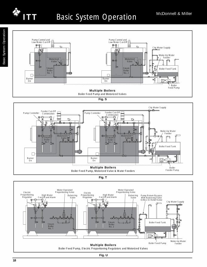
Meeting the Needs of Systemswith Multiple Steam Boilers(Fig. S, T U)
he boiler on the right may be a stand-by to the boileron the left. Every week or so, a boiler attendant
might switch them, making this one the operating boilerand the other the stand by.
It’s a good idea, one we’ve used for years in larger boilerrooms. By having more than one boiler, each is able tosupply the entire needs of the system. Your chances ofgetting caught without steam are much less.
Some systems have multiple steam boilers. The ideahere is to let several boilers join forces to meet the totalneeds of the system. The goal is energy conservation.You steam all the boilers on start-up, and then shut a fewdown after you’ve heated the system and satisfied thepiping pick-up load. In other words, you put the systemon “simmer” after you’ve heated it completely.
Steam systems with more than one boiler often haveproblems if the installer fails to realize that steam isdynamic and not static. By this, we mean that steam isalways moving very quickly from the boiler to the system,and as it moves, it loses pressure. And since one ounceof pressure represents a water column 13/4 in. (45mm)high, the slightest difference in pressure between anytwo boilers interconnected on their return sides can makea big difference in the individual water levels.
A slight burr in a pipe or fitting can create a drop inpressure. You can never tune two burners to produce thesame flame. One boiler will always be closer to thesystem take-off than another. These things speak loudlyfor proper piping and thoughtful management of theboiler water line so that’s what we’ll look at next.
T
Multiple Boiler Systems with a Boiler FeedPump and Motorized Return ValvesHere we have two boilers served by a single boiler feedpump (Fig. S). One boiler may be a stand by to the other,or they may be sharing the total load. For pipingpurposes, we’d handle either application the same way.
Notice how the condensate returns are independent.Each flows from the boiler feed pump receiver to theboiler through a motorized valve. This is an importantdetail. If you were to interconnect the returns, the waterfrom one boiler would flow into the other.
Steam Moves – Remember, steam is dynamic, not static.Water doesn’t “seek its own” level when the steam ismoving out of the boiler. The slightest difference in firingrate or piping pressure drop between the two boilers willcause one to flood and the other to shut down due to alow water condition. This is why those independentreturns are important. We’re using motorized valves onthis installation (Fig. S) to isolate one boiler from theother. When either boiler needs water, the McDonnell &Miller pump controller on that boiler will drop to a pointwhere it will close the higher of its two switches. Thatswitch will power that boiler’s motorized valve, causing itto open. When it’s fully opened, the motorized valve willtrip an end switch and start the boiler feed pump. Waterwill flow only to the boiler that needs it. The float in thepump controller will sense the rising water. When thewater reaches the proper level, the pump controller willbreak the electrical connection to the motorized valve.The valve will begin to close, shutting off the boiler feedpump as it does.
As you can see, when we pipe multiple boilers this way itdoesn’t matter how big or small each is. The boiler feedpump, although sized for the total needs of all the boilers,will satisfy the needs of each in turn, no matter what size.
Keeping the Water Flowing – We’ve installed a make-upwater feeder in the boiler feed pump’s receiver tank. It’sjob is to maintain a minimum water line in the tank so thepump will always have a reservoir from which it can drawfeed water. In this system, all the water will enter theboilers through the boiler feed pump. If, for any reason,the boiler feed pump can’t keep up with the boiler’s rateof evaporation, the water line in the boiler will drop. Thelower switch in the McDonnell & Miller pump controllerwill stop the burner.
03. Basc Systm Oprtn9-26 COLLECT 3/7/07 11:03 AM Page 17
18
Bas
ic S
yste
m O
per
atio
nB
ASIC
SYSTEM
OPER
ATIO
N
Basic System Operation McDonnell & Miller
BurnerOn
BurnerOn
Pump Control andLow Water Cut-Off
Pump Control andLow Water Cut-Off
MotorizedValve
MotorizedValve
SteamBoilerNo. 1
SteamBoilerNo. 2
City Water Supply
Make-Up WaterFeeder
Boiler Feed Tank
BoilerFeed Pump
Multiple BoilersBoiler Feed Pump and Motorized Valves
Feeder Cut-OffCombination Feeder Cut-Off
Combination
MotorizedValve
MotorizedValve
BurnerOn
BurnerOn
SteamBoilerNo.2
SteamBoilerNo.1
City Water Supply
Boiler Feed Tank
BoilerFeeder Pump
Make-Up WaterFeeder
Pump Controller Pump Controller
Multiple BoilersBoiler Feed Pump, Motorized Valve & Water Feeders
ElectricProportioning
Regulator
ElectricProportioning
Regulator High Water
Cut-Off and Alarm High Water
Cut-Off and Alarm
SteamBoilerNo. 1
SteamBoilerNo. 2
Motor OperatedProportioning Valve
Motor OperatedProportioning Valve
Balancing Valve
Balancing Valve
Boiler Feed Tank
City Water Supply
Make-Up WaterFeederBoiler Feed Pump
Pump Return By-passWith Balancing ValveOrifice Or Relief Valve
Multiple BoilersBoiler Feed Pump, Electric Proportioning Regulators and Motorized Valves
Fig. S
Fig. T
Fig. U
03. Basc Systm Oprtn9-26 COLLECT 3/7/07 11:03 AM Page 18

19
BA
SICS
YSTEM
OPER
ATIO
N
Basic System
Op
eration
Basic System Operation McDonnell & Miller
If you find the pump suddenly can’t keep up with theboiler’s needs, check the temperature of the returningcondensate. As thermostatic radiator steam traps andend of main F&T traps age and fail, they pass steam intothe returns. That can make the condensate hot enoughto “flash” when it hits the pump’s impeller. Boiler feedpumps can’t move water once it has flashed to steam.The pump will turn and cavitate, but it won’t satisfy theboiler.
Ideally, in a low pressure steam heating system, thecondensate in the pump’s receiver shouldn’t be hotterthan 180°F (82°C).
Multiple Boiler Systems with a Boiler FeedPump, Motorized Return Valves and BoilerWater Feeders (Fig. T)
This is the same system we just looked at, except we’veadded a combination automatic water feeder and lowwater cut-off to a point just below the pump controller.The feeder/cut-off’s job will be to add water mechanicallyto the boiler should something happen to the boiler feedpump (for instance, if it’s cavitating because the returncondensate is too hot).
Think of the feeder/cut-off as a back-up device to keepthe boiler in operation should something go wrongelsewhere. The low water cut-off will back up the pumpcontroller’s primary low water cut-off should somethinggo wrong there, or if the feeder can’t keep up with theboiler’s rate of evaporation for some reason.
Multiple Boiler Systems with a Boiler FeedPump, Motorized Return Valves and ElectricProportioning Regulator (Fig. U)
Here we’re controlling the water lines with electricproportioning regulators. We’re matching the incomingfeed water to the exact amount of water that’s leaving assteam. By doing this, we’re able to maintain a precisewater line in both boilers and take advantage of eachboiler’s full steaming space.
There are times when steaming loads will varytremendously. This is especially true of steam heatingsystems in larger buildings. We often set up thesebuildings to operate on outdoor air temperature sensorsand night set-back devices. When the system first startsin the morning the boilers will steam longer than they willduring the day when the pipes and radiators are hot. Thisis also true of seasonal operation when you run theheating system less often.
This is when proportioning regulators can make a bigdifference. By closely monitoring the water line,regardless of varying system conditions, you improve thequality of steam leaving the boiler and allow the systemto operate more efficiently.
Basic System
Op
eration
03. Basc Systm Oprtn9-26 COLLECT 3/7/07 11:03 AM Page 19

Receiver Tank Controlf you size a boiler feed pump’s receiver properly it willbe able to hold the right amount of water to keep the
boiler operating during the start-up cycles. It will also beable to receive the returning condensate withoutoverflowing.
Receiver sizing is more an art than a science. You haveto look closely at the entire system to figure out how longit will take the condensate to return from the building.There are many variables to consider: The type andcondition of steam traps, the pitch and cleanliness ofsteam mains and returns, the pipe insulation or lack of it,the shape of the building and how people use it.
There are also the times when you’ll have to deal withcondensate transfer pumps, or maybe a vacuum/con-densate pump. These pumps collect and relay returnwater back to the boiler feed pump. There are manythings that can affect how quickly these secondarypumps move condensate back to the primary boiler feedpump. You have to consider them all when you’re sizinga feed pump receiver.
One thing will be a constant, however. There mustalways be enough water in the receiver for the boiler todraw from during the start-up cycle (the time betweeninitial steaming and the return of condensate from thebuilding). A McDonnell & Miller make-up feeder, set atthe one-third full point on the receiver tank, will meet theboiler’s needs during this crucial start-up time. Let’s takea closer look at these.
Receiver Tank Make-Up Water Feeders Here, we’ve mounted a McDonnell & Miller make-upwater feeder on a one-inch NPT equalizing line thatextends from the top of the tank to the bottom. The levelin the feeder’s chamber will be the same as the level inthe tank. As the pump moves water out of the tank andinto the boiler, the float inside the feeder’s chamber willopen and constantly replenish the tank’s reservoir.
We’ve designed our feeders with the right amount of floatand lever power to close tightly against city waterpressure. This ensures that there will always be enoughtank space to receive the returning condensate withouthaving it overflow.
If the tank you’re using doesn’t have tappings for anequalizing line, you can use our internal feeder (Fig. V).As you can see, it mounts directly inside the tank andfeeds water through its integral strainer. We make thisunit with two flange sizes for both new and retrofitinstallations.
20
Bas
ic S
yste
m O
per
atio
n
Basic System Operation McDonnell & Miller
I
Condensate Receiver Tank
City Water Supply
Model 21Make-Up Water
Feeder
Make-Up Water Feeder
Fig. V
03. Basc Systm Oprtn9-26 COLLECT 3/7/07 11:03 AM Page 20

21
Basic System
Op
eration
Basic System Operation McDonnell & Miller
City Water Supply
Make-Up WaterFeeder
BoilerFeed Pump
Low WaterCut-Off
Condensate Receiver Tank
Low Water Cut-Offon Receiver Tank
City Water Supply
Cond. Return
Needle Valve
Diaphragm Valve
Check Valve
Model 25AMake-Up Water
Feeder
Large Condensate Receiver Tank
Make-Up Water FeederUsed as Pilot Valve
Large Condensate Receiver Tank
Motorized ValveCity Water
Supply
Model 93Controller
Make-Up Water Feederand Motorized Valve
A Make-Up Water Feeder Used as a Pilot Valve(Fig. W)
When you have multiple boilers, the boiler feed pump hasto be able to meet the needs of all the boilers should theyneed water simultaneously. During the start-up cycle, thedraw from the feed pump’s receiver can be very heavyand the make-up feeder has to be able to match that flow.
When we run into this situation, we often use a make-upwater feeder as a pilot valve to operate a high capacitydiaphragm valve with “dead-end” service. When thefeeder opens it signals the diaphragm valve to snap intoaction. The larger valve quickly maintains the receiver atthe one-third full point. Once the feed pump shuts off thedead-end service valve closes tightly to prevent overfilling. If returned condensate fills the receiver, the feedvalve, of course, stays closed. This piping arrangementalso gives you a lot of freedom because you can put thediaphragm valve in a remote location, if you’d like, foreasier service.
A Make-Up Water Feeder with a Motorized Valve(Fig. X)
Here’s another way you can quickly fill the receiver. Usea McDonnell & Miller controller to sense the tank’s waterline. As the level rises and falls, the controller willelectrically operate a high capacity motorized valve. Thisis another piping arrangement that gives you a lot offreedom. You can place that motorized valve anywhereyou’d like.
Low Water Cut-Offs for Receiver Tanks(Fig. Y)
There’s always the possibility for human error on any job.For instance, suppose someone decides to turn off thewater supply to your receiver tank. The pump controlleron the boiler will still start the pump, but once the receivergoes dry there won’t be any water to pump because ofthe closed valve. Or suppose the building loses waterpressure and the feed pump suddenly finds itself movingmore water than the water feeder can replace. If thepump runs dry, it will cavitate and its mechanical seal willquickly heat and break. That leaves you with a costlyrepair and system down time.
If you install a low water cut-off in an equalizing linearound the tank, the cut-off will protect the pump nomatter what happens.
Fig. W
Fig. X
Fig. Y
03. Basc Systm Oprtn9-26 COLLECT 3/7/07 11:03 AM Page 21

22
Bas
ic S
yste
m O
per
atio
n
Basic System Operation McDonnell & Miller
BurnerOn
Compression Tank
ColdWaterSupply
Low WaterFuel Cut-Off
Series 63
Test-N-Check®
Valves
Blow DownValve
Hot Water Boiler
ASME ReliefValve
Series 850 or 900Low WaterCut-Offs
ReturnMain
Supply Main
Hot Water Boiler
Hot Water Boilersow water protection isn’t just for steam boilers. Hotwater boilers face the same perils of overheating
damage if the water line drops too low. Many peopledon’t think of this as often as they should because hotwater boilers serve “closed” systems. They havepressure reducing valves that are supposed to feedwater automatically should a leak develop.
The truth, however, is that a pressure reducing valve is nosubstitute for a low water cut-off. Pressure reducing, or“feed” valves, often clog with sediment and wind up notfeeding at all. A buried pipe can corrode and spring a leakthat flows faster than a “feed” valve can satisfy. Reliefvalves can pop and, while dumping water at a great rate,actually prevent the feed valve from operating.
Let’s take a closer look at how we can protect these boilers.
Hot Water Systems (Fig. Z)As we said, the things that affect steam boilers also affecthot water boilers. If you run them with too much water therelief valve will open. If you run them with too little waterthey’ll overheat and suffer damage.
A low water cut-off is the only sure way of protecting a hotwater boiler from sudden loss of water. The ASME boilercode recognizes this by requiring all hot water boilers of400,000 BTU/HR or more input to have low water fuel cut-off devices.
ASME doesn’t call for low water cut-offs on smaller,residential boilers, but we think all hot water boilers,regardless of their size, must have protection. However,the International Mechanical Code requires low water cut-offs on ALL hot water and steam boilers. ITT McDonnell& Miller makes several devices, both float and probe type,that protect and meet the needs of any boiler whether it’scast iron, steel, or copper construction (Fig. AA, BB, CC).
Hot water systems regularly lose water through faulty airvents, loose valve stem packing, cracked boiler sections,loose nipples, corroded pipes, broken or loose pump seals,leaking gaskets, dripping relief valves, to name just a fewplaces. Most installers depend on their pressure reducingor feed valve, to replace the lost water automatically. Butfeed valves often clog with sediment, especially in hardwater areas. And it’s very easy to close the supply valve toa feed valve and forget to open it again.
Fig. Z
On systems with buried pipes (say, a radiant heatingsystem) a feed valve will open if a pipe breaks. It will feedfresh water continuously until it either clogs (and stopsfeeding) or destroys the ferrous components of thesystem with oxygen corrosion. A simple feed valve canwind up costing a lot more than its purchase price. This iswhy major suppliers of feed valves, such as ITT Bell &Gossett, recommend you close the feed valve onceyou’ve established your initial fill pressure.
This is also why we strongly recommend you use a lowwater cut-off on every hot water boiler. Feed valves arenot a substitute for low water cut-offs. They can't protectyour boilers from a low water condition. Feed valves arefine for filling the system initially, and for helping you ventair from the radiators. But once the system is up andrunning, you shouldn’t look to them for protection.
L
03. Basc Systm Oprtn9-26 COLLECT 3/7/07 11:03 AM Page 22

23
Basic System
Op
eration
Basic System Operation McDonnell & Miller
Series PS-851 Probe Type Low Water Cut-Off
Series 67 Float Type Low Water Cut-Off
Series RB-24 Probe Type Low Water Cut-Off
Over firing
There are times when hot water boilers don’t lock-out onsafety. Whether by control failure or human error, thingsgo wrong. And when they go wrong in a hot waterheating system, the water temperature can rise quickly toa point where the compression tank can’t take up theexpansion of the water. This causes the relief valve todischarge.
When the relief valve opens, there’s a sudden drop insystem pressure. The water, which at this point isprobably much hotter than 212°F (100°C), will flash intosteam. This is why ASME insists that relief valves for hotwater boilers carry steam-discharge ratings.
If a feed valve doesn’t open to replace this rapidly exitingwater, a low water condition will quickly result. The onlything that can protect the boiler at this point is a low watercut-off. The feed valve can’t protect the boiler because itstypical setting is 12 psig (.83 bar). In other words, thesystem pressure must drop below 12 psig (.83 bar)before the feed valve will open.
The trouble is that while the relief valve is open andflashing steam to atmosphere, the internal systempressure never drops anywhere near 12 psig (.83 bar). Arelief valve with a 30 psig (2.1 bar) setting, for instance,will open at 30 psig (2.1 bar), and close again when thepressure drops to about 26 psig (1.79 bar). The result isa loss of water with no make-up. Repeat this cycleenough times and the boiler will be in a dangerous, lowwater condition. Keep in mind, steam exerts pressure. Itcan easily fool a feed valve, and that’s why feed valvesoffer very little protection at all against low water.
Fig. AA
Fig. BB
Fig. CC
03. Basc Systm Oprtn9-26 COLLECT 3/7/07 11:03 AM Page 23

24
Bas
ic S
yste
m O
per
atio
n
Basic System Operation McDonnell & Miller
CirculatingPump
Cold Water Supply
Pressure ReducingValve with Built-inCheck Valve
Return fromSystem
Relief Valve
Compression Tank
Flow
Flow Switch Zone ControlValves
Flow Bypass Line
Compression Tank
City WaterSupply
Feeder Cut-OffCombination
Model 247-2, 51-2,51-S-2, 53-2
WaterLevel
Return
Test-n-Check®
Valves
Blow DownValve
BurnerOn
ASME ReliefValve
Supply Main
Series 850 or 900Low WaterCut-Offs
Return
Series FS4-3 Flow Switch(shown without paddle)
Hot Water Boiler
Copper Fin Tube Boiler
Feeder/Cut-Off Combinations for Cast Ironand Steel Hot Water Boilers (Fig. DD)To protect a boiler from dry firing, the low water cut-offmust located above the boiler’s crown. After the low water cut-off shuts off the burner, you should have a wayto add water to the system to ensure the crown stays under water.
A combination water feeder and low water cut-off can dothis for you. If you position the feeder above the boiler’scrown, it will mechanically feed water if the level shoulddrop to that point. This is an important considerationbecause, even if the electricity is cut off, it’s possible forthe firing cycle to continue if the fuel feed valve ismechanically locked open. The combination unit’s cut-offswitch will act as a back-up to the primary low water cut-off, providing the boiler with additional protection.
Protecting Copper Fin Tube Boilers (Fig. EE)Copper fin tube boilers move heat from the flame to thewater almost instantly. This type of boiler depends on theproper flow of water across its heat exchanger to movethe heat quickly out of the boiler and into the system.Should flow stop while the burner is operating, heat willquickly build and cause the water in the heat exchangerto flash into steam. This condition is similar to a dry firingin a cast iron or steel boiler.
A McDonnell & Miller flow switch, installed on the copperfin tube boiler’s hot water outlet, protects it from thisdanger (Fig. FF). The burner cannot fire unless water ismoving across the flow switch. When the flow stops, forwhatever reason, the McDonnell & Miller flow switchimmediately cuts electrical power to the burner andprotects the boiler from overheating.
Fig. FF
Fig. DD
Fig. EE
03. Basc Systm Oprtn9-26 COLLECT 3/7/07 11:03 AM Page 24

25
Basic System
Op
eration
Basic System Operation McDonnell & Miller
Series 250 Pressure Relief Valve
Series 260 Pressure Relief Valve
Pressure Relief Valves(Fig. GG, HH)
ood engineering practice calls for every hot waterboiler to have a pressure relief valve. This spring-
loaded valve must be able to release the boiler’s entireload at the boiler’s maximum operating pressure.
Here are some things that can cause a relief valve toopen in a hot water heating system:
• The automatic feed valve fails, allowing higher than normal pressure to enter the system.
• Someone leaves a hand bypass line open after filling the system.
• Someone hydrostatically tests the system at a pressure greater than the relief valve’s setting.
• The air cushion in the diaphragm type compression tank doesn’t match the system’s static fill pressure. Keep in mind, most tanks come from the factory precharged at 12 psig (.83 bar). If the system needs more than 12 psig (.83 bar) pressure, you have to addmore air to the tank, and you have to do this while youhave the tank disconnected from the system.
• The compression tank may be too small for the system.• The boiler’s aquastat is in a well without heat
transfer grease. When this happens, the boiler’s temperature will quickly exceed the aquastat’s setting, causing rapid rise in system pressure.
• The circulator may be on the return side of the system with the compression tank at its suction. If it is, the circulator’s head pressure will appear inside the boiler as a net increase. It may be enough to open the relief valve.
• The burner limit may be jumped-out or stuck in a manual position.
The main thing to keep in mind when you’retroubleshooting this one is that relief valves pop whenany of these three things happen:
• The compression tank loses it’s air cushion• The system takes on more water.• The system temperature increases.
Think methodically, and keep your eyes wide open!
e hope this Basic System Operation Guide hasgiven you insight into the systems on which you’re
now working or will face in the future. We welcome anyquestions or comments you may have about the Guide,or about our products.
Thanks for your support, and for your continuing business.
Fig. GG
Fig. HH
G
W
03. Basc Systm Oprtn9-26 COLLECT 3/7/07 11:03 AM Page 25

26
Boiler Controls McDonnell & Miller
Maximum Method of Installation Blow Down ValveBoiler Directly into
Pressure Boiler Tappings To Piping Above the Provided withpsi (kg/cm2) OR on the Boiler Boiler with 1" (25mm) Product Size Low Water
Supply Riser* Equalizing Piping Series NPT Required Cut-OffX RB-24 3⁄4 No N/A
X 63 1 Yes No
50 (3.5) X 64 1 Yes No
X 64-A 1⁄2 Yes Yes
X 764 21⁄2 Yes No
160 (11) X PS-850 3⁄4 No N/A
X RB-120 3⁄4 No N/A
X RB-122E 3⁄4 No N/A
160 - 250 (11-18) X 750/750B/750P 3⁄4 - 1 No N/A
McDonnell & Miller Low Water cut-offs are speciallydesigned to protect hot water boilers from the hazards ofa low water condition. In operation they will interrupt theelectrical current to the firing device, if the water in thesystem drops below the boiler manufacturer’s minimumsafe water level.
Our low water cut-offs also provide an additional circuit fora low water alarm, should you desire to install one, foradditional protection.
How to Select Low WaterCut-Offs for Hot Water BoilersBoiler pressure and the method of mounting are theprimary factors to consider when selecting a low watercut-off.
Hot Water Boilers
* Use the tapping designated by the boiler manufacturer for low water cut-off installation.
Boile
r C
ontr
ols
03. Basc Systm Oprtn9-26 COLLECT 3/7/07 11:03 AM Page 26