Embed Size (px)
Citation preview
Basic PLC Progrmming

Outline
� Introduction to Programming Software
� Ladder Diagram
� Basic Logic Functions
� Mnuemonic Code
� CX-Programmer

Flowchart

Ladder Diagram� Primary programming language for PLCs.� Other programming methods include:
� Function block diagrams (FBDs)� Structured text (ST)� Instruction List (IL)� Sequential function charts (SFCs)
� Visual and Graphical language unlike textual high-level, such as C, C++, Java…
� Derived form relay logic diagrams� Primitive Logic Operations
� OR� AND� NOT

Ladder Diagram
Ladder Diagram
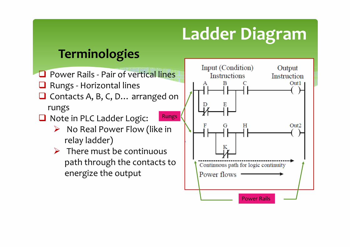
� Power Rails - Pair of vertical lines� Rungs - Horizontal lines� Contacts A, B, C, D… arranged on
rungs� Note in PLC Ladder Logic:
� No Real Power Flow (like in relay ladder)
� There must be continuous path through the contacts to energize the output
Terminologies
Power Rails
Rungs
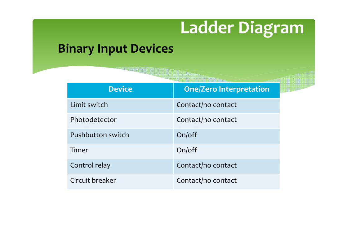
Ladder DiagramBinary Input Devices
Device One/Zero Interpretation
Limit switch Contact/no contact
Photodetector Contact/no contact
Pushbutton switch On/off
Timer On/off
Control relay Contact/no contact
Circuit breaker Contact/no contact
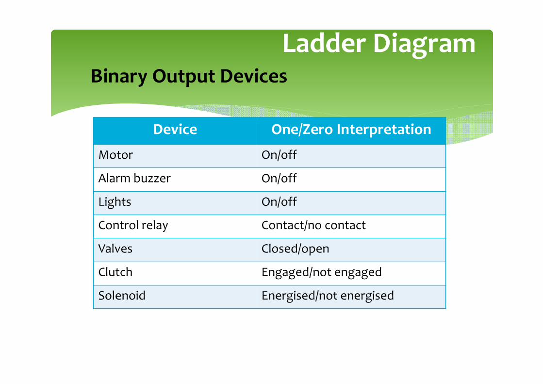
Ladder DiagramBinary Output Devices
Device One/Zero Interpretation
Motor On/off
Alarm buzzer On/off
Lights On/off
Control relay Contact/no contact
Valves Closed/open
Clutch Engaged/not engaged
Solenoid Energised/not energised

Anatomy of Ladder Diagram
o

Anatomy of Ladder Diagram
� Input instructions are entered on the left� Output instructions are entered on the right� The power rails simulate the power supply lines
� L1 and L2 for AC circuits and +24V and ground for DC circuits
� Most PLCs allow more than one output per rung� The processor (or “controller”) scans ladder
rungs from top-to-bottom and from left-to-right.� The basic sequence is altered whenever
jump or subroutine instructions are executed.

Basic Ladder Logic Symbols

Logic Functions
� PLC programming is a logical procedure� In a PLC program, “things” (inputs and rungs) are
either TRUE or FALSE� If the proper input conditions are TRUE:
� The rung becomes TRUE and an output action occurs (for example, a motor turns on)
� If the proper input conditions are not TRUE:� The rung becomes FALSE and an output action
does not occur
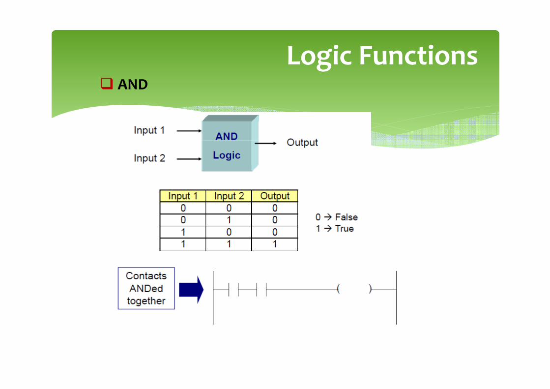
Logic Functions� AND
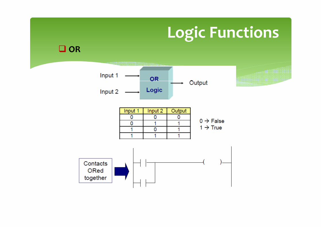
Logic Functions� OR

Logic Functions� NOT
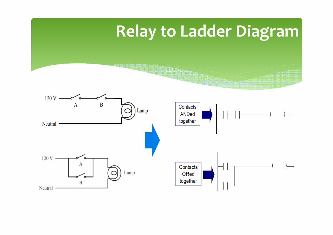
Relay to Ladder Diagram
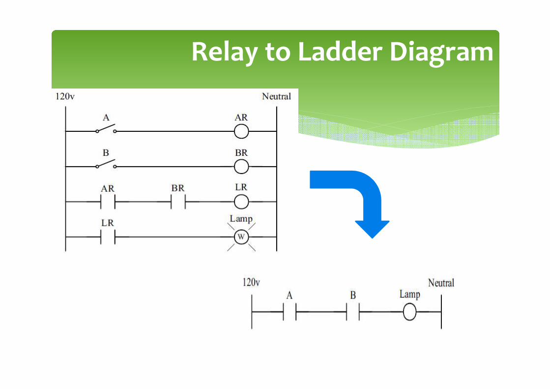
Relay to Ladder Diagram

Mneumonic Codes
� These instructions can be derived directly from the ladder
logic diagrams and entered into the PLC through a simple
programming terminal.
� Ladder logic diagrams can be read by the programming
console
� For this reason, ladder diagrams need to be converted into
mnuemonic codes that provides same information as ladder
diagrams and to be typed directly using programming
console.
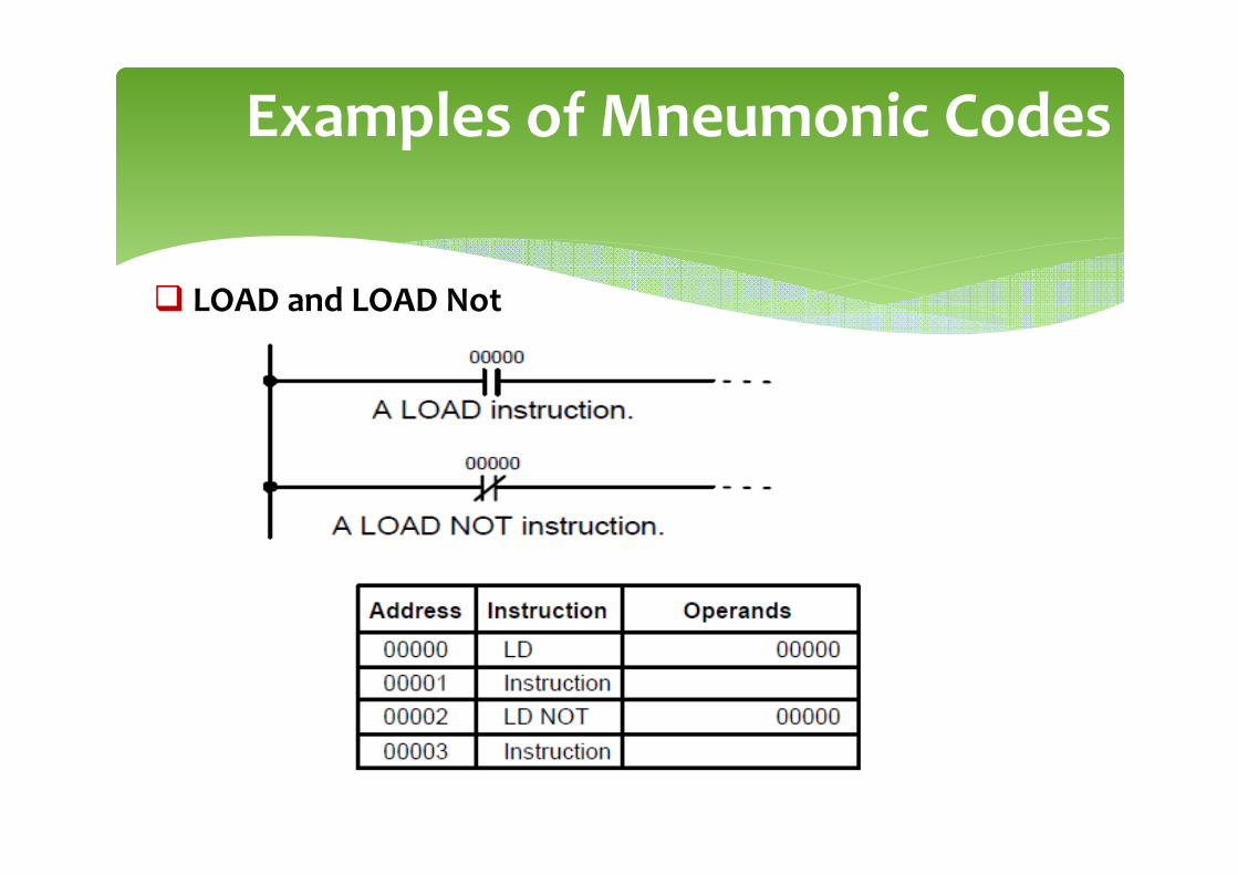
Examples of Mneumonic Codes
� LOAD and LOAD Not
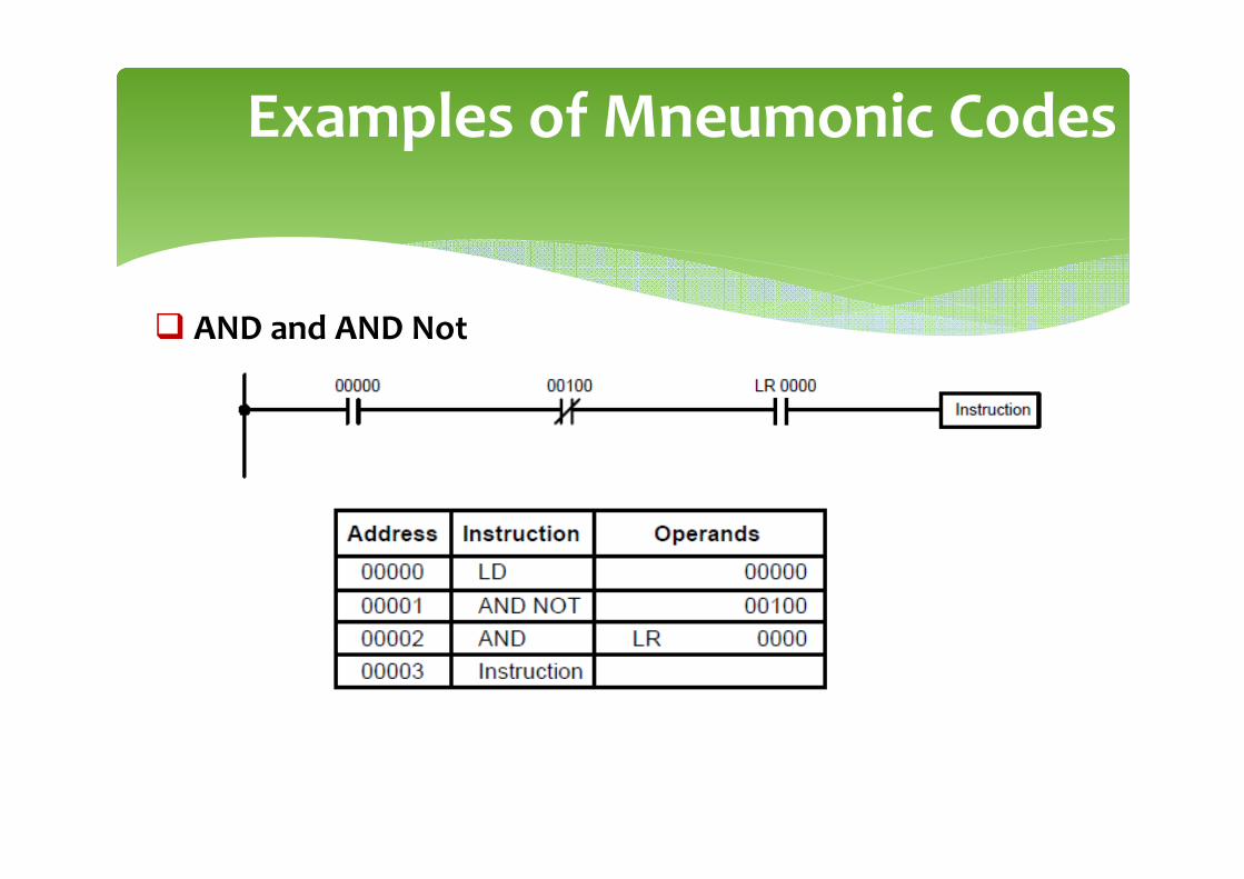
Examples of Mneumonic Codes
� AND and AND Not
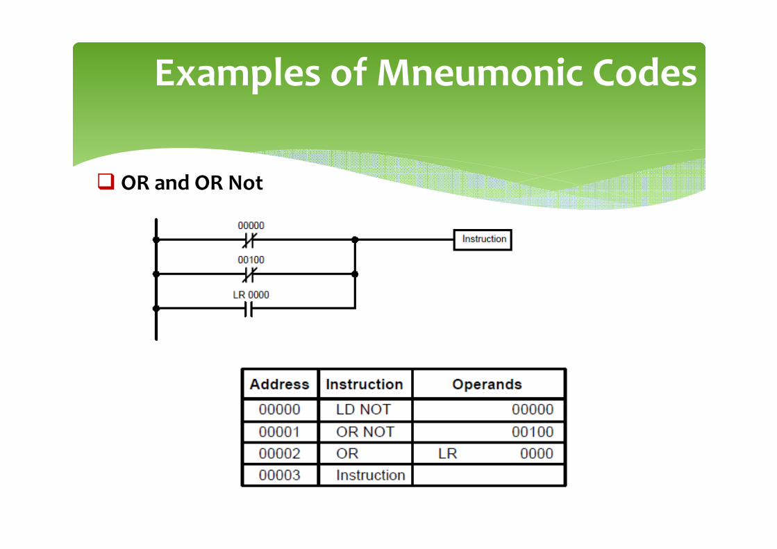
Examples of Mneumonic Codes
� OR and OR Not
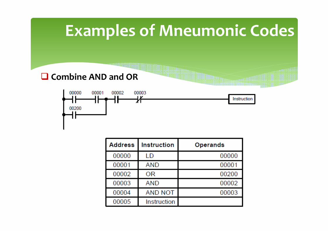
Examples of Mneumonic Codes
� Combine AND and OR
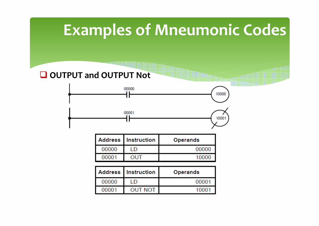
Examples of Mneumonic Codes
� OUTPUT and OUTPUT Not
Examples of Mneumonic Codes
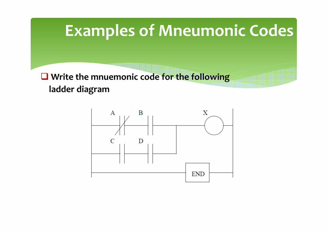
� Write the mnuemonic code for the following
ladder diagram
� CX-Programmer, the programming software for all Omron's PLC series,
is fully integrated into the CX-One software suite.
� CX-Programmer includes a wide variety of features to speed up the
development of your PLC program. New parameter-setting dialogues
reduce setup time, and with standard function blocks in IEC 61131-3
structured text or conventional ladder language, CX-Programmer makes
development of PLC programs a simple drag & drop configuration.
Entering the Ladder Diagram:CX Programmer

CX Programmer
©snaim 2008

CX Programmer: Overview
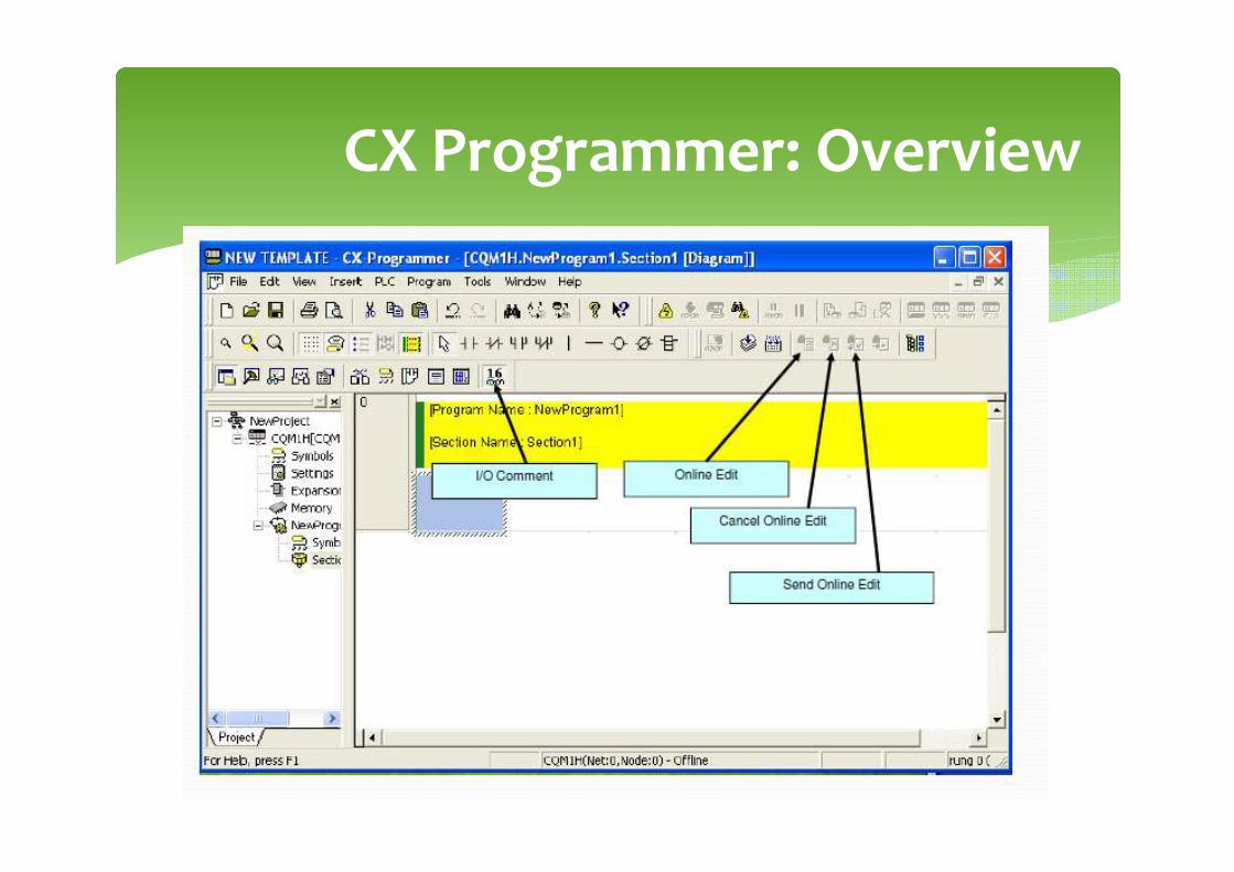
CX Programmer: Overview
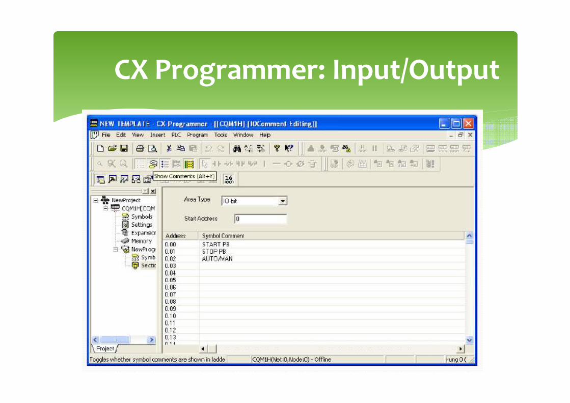
CX Programmer: Input/Output
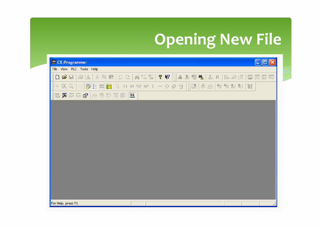
Opening New File

Configure PLC Devices
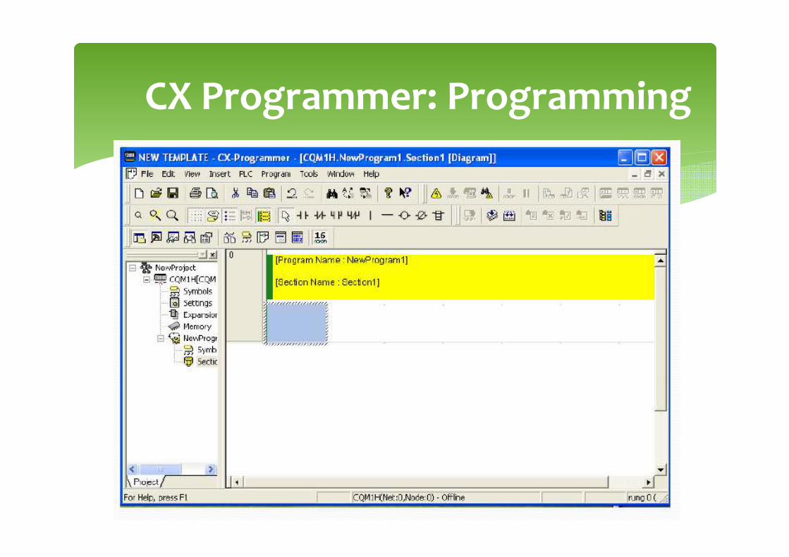
CX Programmer: Programming

PLC Mode

Exercise
� Draw process flowchart for a given system
� Create the ladder diagran in CX Programmer

Program Error Check (Compile)
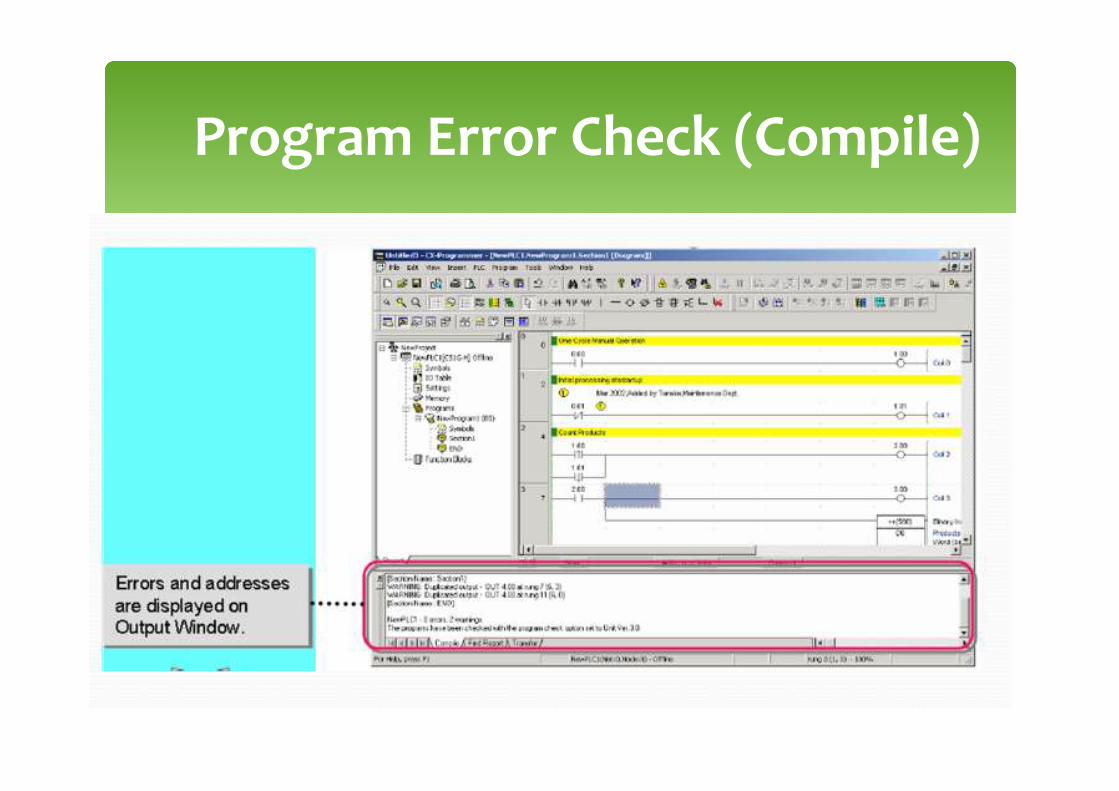
Program Error Check (Compile)
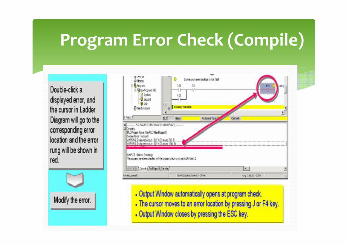
Program Error Check (Compile)

Going Online
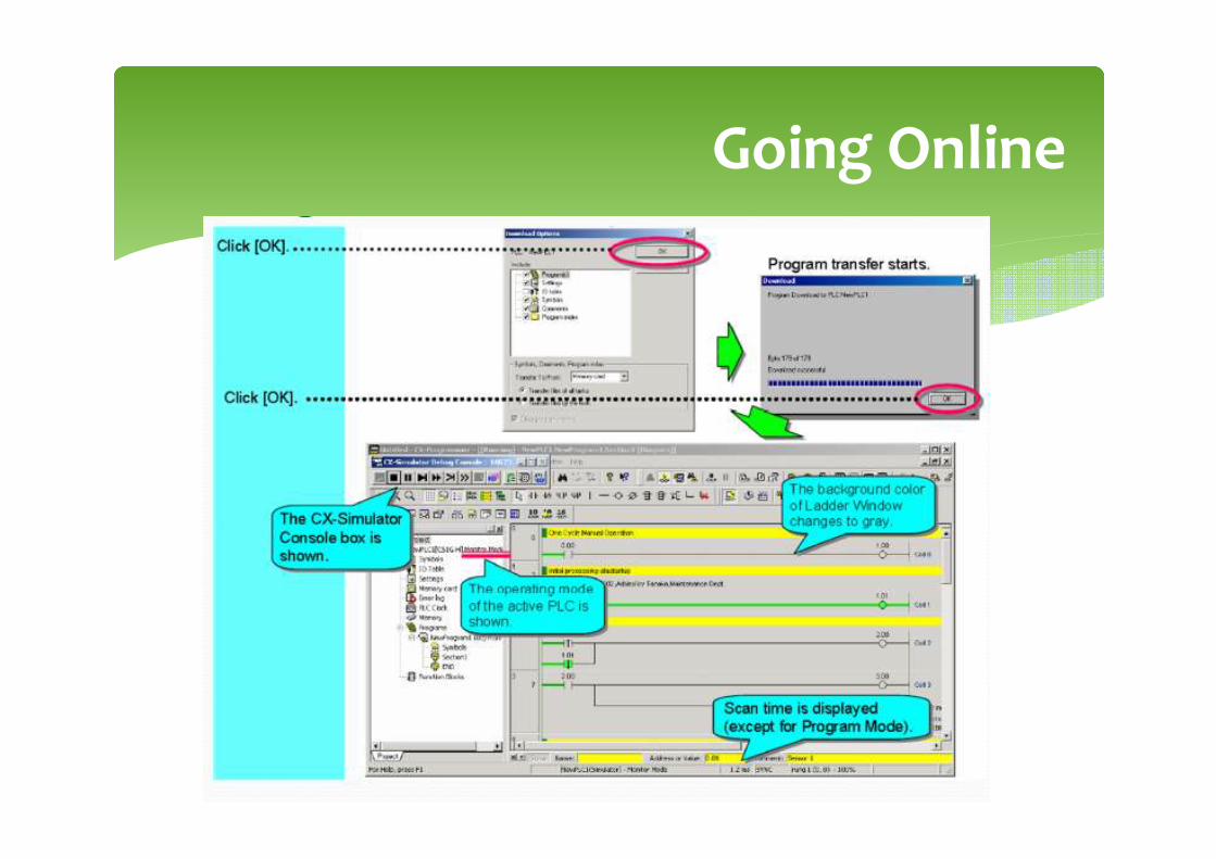
Going Online