Embed Size (px)
Citation preview

BASIC PARAMETERS FOR THE
TRAMWAY TRACK ALIGNMENT
TABLE OF CONTENTS
1. INTRODUCTION ............................................................................................................. 2
ALIGNMENT OF TRAMWAY CORRIDOR ..................................................................................... 3
Α1. BASIC PRINCIPLES AND REQUIREMENTS OF THE DESIGN STUDY ........................ 3
Α2. BASIC DESIGN PRINCIPLES ........................................................................................ 3
Α3. REINSTATEMENT OF ROADS AND PAVEMENTS ..................................................... 15
Β1. GENERAL ....................................................................................................................... 22
Β2. CURVED SECTIONS ..................................................................................................... 23
Β3. CANT .............................................................................................................................. 24
Β4. TRANSITION ARCS ....................................................................................................... 26
Β5. CANT TRANSITIONS (RAMPS) .................................................................................... 28
Β6. LONGITUDINAL PROFILES .......................................................................................... 29
Β7. DETERMINATION OF MAXIMUM ALLOWABLE
SPEED DUE TO TRACK ALIGNMENT .......................................................................... 30

SPECIFICATIONS DOCUMENT
1. INTRODUCTION
The present document gathers all specifications which are adhered to in the preparation of the
design concerning the Tramway Line extension.
Part A provides the principles for the alignment design and the reinstatement of roads,
pavements, pedestrian streets and heavy traffic areas. (Source: Design and Performance
Specifications, TRAM S.A. 2001).
Part B provides the basic parameters for track alignment design related to fixed route modes
running at speeds less than 100km/h. (Source: Low Speed Track Alignment Instructions, ΝΑΜΑ
Α.Δ., April 2002).

ALIGNMENT OF TRAMWAY CORRIDOR
PART A
GENERAL PRINCIPLES FOR THE TRAMWAY ALIGNMENT DESIGN AND
REINSTATEMENT OF ROADS AND PAVEMENTS
Α 1. BASIC PRINCIPLES AND REQUIREMENTS OF THE DESIGN STUDY
The design study‟s basic principles and requirements shall be in accordance with
the Approved Regulations and Specifications described herebelow:
PD 696/74: Technical specifications for design studies
Standard Technical Specifications for Roadworks, issued by the Ministry
of Public Works Configuration of Cross-Sections for Greek Roads No. 103/1.Δ 60-62,
Ministry of Public Works – Transport Projects Division – Dept. C.2
Α POLlCY ΟΝ GEOMETRIC DESIGN OF HIGHWAYS ΑΝD
STREETS. American Association of State Highway and
transportation Officials, (AASHTO), Washington D.C., 1994.
Basic design principles, as stated below.
Α2. BASIC DESIGN PRINCIPLES
LATERAL ACCELERATION
On each curve with an “r: radius, lateral acceleration aq is developing (both on the vehicle and the
passengers) equal to:
Where aq
v r
u
lateral acceleration [m/s2]
speed [kph]
curve radius [m]
cant [mm]
For reasons of comfort, the lateral acceleration aq shall not exceed the value of 0.65 m/s2. At critical
sections, TRAM S.A. also accepts lateral acceleration in the order of 0.98 m/s2. The lateral
acceleration value is also correlated to the calculation of the maximum permissible speed:
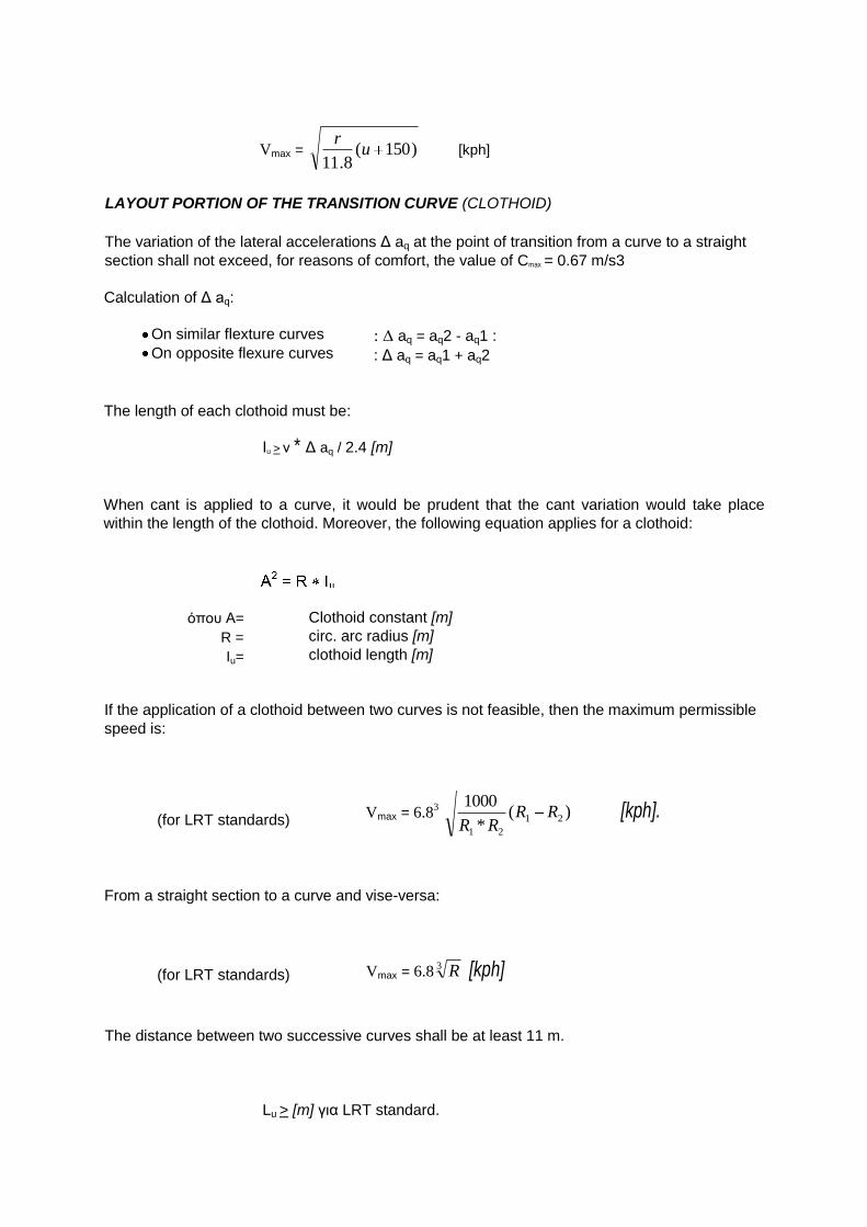
Vmax = )150(8.11
ur
[kph]
LAYOUT PORTION OF THE TRANSITION CURVE (CLOTHOID)
The variation of the lateral accelerations Γ aq at the point of transition from a curve to a straight
section shall not exceed, for reasons of comfort, the value of Cmax = 0.67 m/s3
Calculation of Γ aq:
On similar flexture curves
On opposite flexure curves : Δ aq = aq2 - aq1 :
: Γ aq = aq1 + aq2
The length of each clothoid must be:
Ιu > ν * Γ aq / 2.4 [m]
When cant is applied to a curve, it would be prudent that the cant variation would take place
within the length of the clothoid. Moreover, the following equation applies for a clothoid:
όποσ Α=
R =
Iu=
Clothoid constant [m]
circ. arc radius [m]
clothoid length [m]
If the application of a clothoid between two curves is not feasible, then the maximum permissible
speed is:
(for LRT standards) Vmax = 6.8
3 )(
*
100021
21
RRRR
[kph].
From a straight section to a curve and vise-versa:
(for LRT standards) Vmax = 6.83 R [kph]
The distance between two successive curves shall be at least 11 m.
Lu > [m] για LRT standard.
If this criterion is not met, the permissible speed should be calculated as if no straight section
intervenes between the curves.
TRACK CANT
In order to balance the lateral accelerations, it is imperative to apply cant to the curved sections
of the alignment. The cant is obviously chosen in relation to the train speed.
The theoretical cant value is given by the following formula:
U = 11.8 * ν2/ r [mm]
A regular cant Ureg shall not lead to lateral acceleration exceeding the value of aq ≈ 0.2 m/s2. The
mathematical equation then becomes:
Ureg = 11.8 * ν2/ r - 152*aq =>Ureg = 11.8 * ν
2/ r - 30 [mm]
The absolute minimum cant leading to lateral accelerations equal to aq = 0.65 m/s2 is given by
the following equation:
regUmin = 11.8 * ν2 / r - 100 [mm]
At critical only sections, TRAM S.A. accepts as an absolute minimum cant the one that
corresponds to lateral accelerations aq = 0.98 m/s2 and is calculated according to the following
equation:
minumin = 11.8 * ν2 / r - 150 [mm]
where ν = Speed [kph]
r = curve radius [m]
The maximum cant between two rails is 150 mm.
At stations and stops the cant shall be zero. The cant at level crossings shall not exceed the
value of 30 mm.
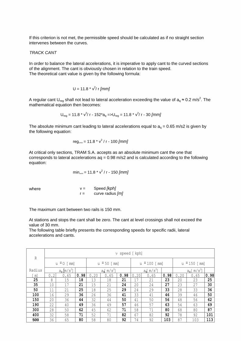
The following table briefly presents the corresponding speeds for specific radii, lateral
accelerations and cants.
R
ν speed [kph]
u = Ο [mm] u = 50 [mm] u = 100 [mm] u = 150 [mm] Radius aq [m/s
2] aq[m/s
2] aq[m/s
2] aq [m/s
2]
[m] 0.2
0
0.65 0.98 0.20 0.65 0.98 0.20 0.65 0.98 0.20 0.65 0.98 25 8 15 18 13 18 21 17 21 23 20 23 25
35 10 17 21 15 21 24 20 24 27 23 27 30
50 11 21 25 18 25 29 24 29 33 28 33 36
100 16 29 36 26 36 41 33 41 46 39 46 50
150 20 36 44 32 44 50 41 50 56 48 56 62
190 22 40 49 36 49 57 46 57 63 54 63 69
300 28 50 62 45 62 71 58 71 80 68 80 87
400 32 58 71 52 71 82 67 82 92 78 92 101
500 36 65 80 58 80 92 74 92 103 87 103 113

RAIL CANT TRANSITION PART (CANT RAMP)
During the transition from a section without cant to another canted section, or from one section to
another section with different cant, a section must intervene where the longitudinal sloping is constant.
Moreover, it is advisable that the length of this section would be same as the length of the clothoid.
The length of the section where cant variation occurs is define by the following equation:
where
IR =
u = 1/m =
m * u Ι 1000 [m]
cant [mm] sloping of section when cant changes
The usual sloping of the part where cant changes is equal to:
where
1/m =
ν = 1/(10*ν) Maximum running speed [kph]
The maximum sloping of the part where cant changes is equal to:
1/m = 1 /(6 * ν)
Moreover, maximum sloping must not exceed 1 :300. Finally, maximum sloping must not be applied at the edge of stations and stops. The following table presents the required length of cant transition for various speeds and cant values.
Speed IR[m]
ν u = Ο [mm] u = 50 [mm] u = 100 [mm] u = 150 [mm]
[kph] minimum regular minimum regular minimum regular minimum
25 7 15 15 30 30 45 45 30 8 15 15 30 30 45 45
35 9 18 15 35 30 53 45
40 11 20 15 40 30 60 45
45 12 23 15 45 30 68 45
50 14 25 15 50 30 75 45
55 15 28 17 55 33 83 50
60 16 30 18 60 36 90 54
65 18 33 20 65 39 98 59
70 19 35 21 70 42 105 63
75 20 38 23 75 45 113 68
80 22 40 24 80 48 120 72
CROSSOVERS (TURNOUTS)
The usual turnouts for various running speeds are presented below:

Designation ΔW 500 - 1 :12 ΔW 300 - 1:9 ΔW 100 - 1:5 ΔW 50 - 1:3,5
Speed LRT
50 [kph] 45 [kph] 30 [kph] 25 [kph]
Radius [m] 500 300 100 50
Angle α [1:] 1 :12 1 :9 1 :5 1:3,5
Length a [m] 20.797 16.615 9.902 7.003
Length b [m] 20.797 16.615 9.902 7.003
Length c [m] 20.797 16.615 9.902 7.003
Length d [m] 1.727 1.835 1.942 1.924
Length e [m] > 34.00 > 25.80 > 15.00 > 11.00
Turnouts on curves:
Designation ΔW 190 - 1:9 ΔW140 - 1:7 ΔW 100 - 1:6 ΔW 50 - 1:6
Speed LRT
35 [kph] 35 [kph] 30 [kph] 25 [kph]
Radius [m] 190 140 100 50
Angle α [1:] 1 :9 1 :7 1 :6 1 :6
Length a [m] 10.523 9.950 8.276 4.138
Length b [m] 16.483 13.224 11.528 10.989
Length c [m] 16.483 13.224 11.528 10.898
Length d [m] 1.820 1.870 1.895 1.800
Length e [m] > 23.50 >19.40 > 16.70 > 13.90

CROSSOVERS
The crossover for various running speeds are presented below :
The letters in italics refer to the smaller distances between rails, without any additional speed
reduction (straight section between two curves 11m.) The proposed applications are presented in bold
characters.

Designation R 190 -1:9 R 140 - 1:7 R 100 - 1:6 R 50 - 1:6 R 50 - 1:6 R 25 - 1:4
Speed LRT
35 [kph] 35 [kph] 30 [kph] 25 [kph] 25[kph] 15 [kph]
Radius [m] 190 140 100 50 50 25
Angle α [1:] 1 :9 1 :7 1 :6 1:6 1 :6 1 :4
Track distance a 3.65 > 4.46 > 4.40 3.65 3.25 3.15
[m]
Totallength Ι [m] 53.896 > 51.120 > 47.352 30.176 27.776 19.755
Tangentt[m] 10.523 9.950 8.276 4.138 4.138 3.078
Straight c [m] 11.732 > 11.000 > 11.000 13.926 11.493 6.833
Length b [m] 32.850 > 31.220 > 30.800 21.90 19.500 12.600
Length e [m] >23.5 > 19.4 > 16.6 > 13.9 >13.9 >27.0
ENVELOPE
The selected vehicle width is 2,40 m. On the vehicle perimeter (static envelope) a gap is required
to accommodate the vertical movement of the vehicle and the probable failures. Some of the
failures are: incorrect suspension, probable vertical and horizontal displacement during
construction. The width of these tolerances must be in the order of 300 mm (and 400 mm when
the vehicle is moving in a tunnel or under a bridge). This latter width is called dynamic envelope.
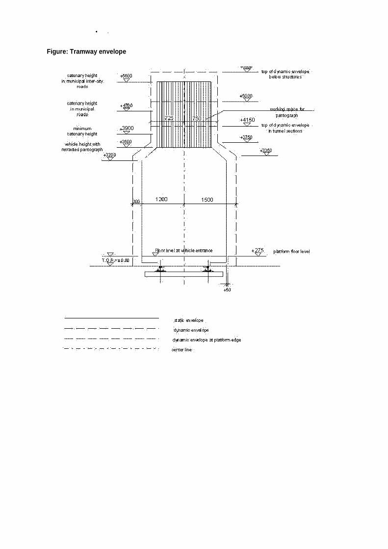
,
Figure: Tramway envelope
statt EI'I\o:lope
-,- - -,- -,- _. •...... ,.. .. dψIarτίc enve\ ope
dΊfιaτιic en'ιJ?lope at platforτrι edge
cemer lίrιe

WIDENING AT CURVED SECTIONS *
R Curve radius (at centre line) W Car Body width =2400mm Α distance between the bogie centre and the front mask bending point =3900mm
Ρ Distance between the Bogie Axles =1700mm
Lρ Suspended Body Length (bearing to bearing) =7100mm
Lc Trailer Body Length (bearing to bearing) =4000mm Rp Bearing Radius Rp=SQRT[R
,2 + (Lc/2)
2]
R' Centre Bogie Radius R'=SQRT[R2 + (Ρ/2)
2]
* Source: Line Interface Data, Ansaldo Breda, 2002
At curved sections, an additional width should be taken into account for either side of the vehicle
width, due to the vehicle‟s larger displacement occupied by the vehicle when located on the
curved section.
These distances (static envelope), on either side of the track axis and for a vehicle 2,40m. wide,
are given in the following table:
The additional dynamic envelope should be added to the valued presented below.
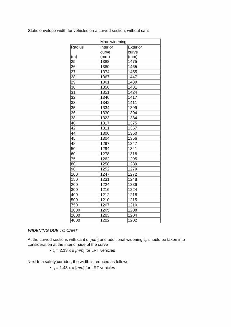
Static envelope width for vehicles on a curved section, without cant
Max. widening
Radius Interior Exterior
curve curve (m) (mm) (mm)
25 1388 1475
26 1380 1465
27 1374 1455
28 1367 1447
29 1361 1439
30 1356 1431
31 1351 1424
32 1346 1417
33 1342 1411
35 1334 1399
36 1330 1394
38 1323 1384
40 1317 1375
42 1311 1367
44 1306 1360
45 1304 1356
48 1297 1347
50 1294 1341
60 1278 1318
75 1262 1295
80 1258 1289
90 1252 1279
100 1247 1272
150 1231 1248
200 1224 1236
300 1216 1224
400 1212 1218
500 1210 1215
750 1207 1210
1000 1205 1208
2000 1203 1204
4000 1202 1202
WIDENING DUE TO CANT
At the curved sections with cant u [mm] one additional widening ts, should be taken into
consideration at the interior side of the curve
• ts = 2.13 x u [mm] for LRT vehicles
Next to a safety corridor, the width is reduced as follows:
• ts = 1.43 x u [mm] for LRT vehicles

WIDENING AND TRANSITION CURVES
The widening depends on the kinematics of the vehicle, starts before the point where the
transition curve commences and reaches its highest value before the curved section. The
widening can be considered as linearly increasing.
Min. distance a [m] b [m]
LRT Exterior curve 15.00 4.00 Interior curve 11.00 0.00
Beginning and end of the widening of the static envelope at a curved section
Note: A 50 mm horizontal distance between the stopping platform and the vehicle is not allowed.
On an LRT platform where the layout radius is lower than 500 m, distance „a‟ should be kept from
the end of the compulsory area.
CROSS - SECTIONS
In case of vehicle evacuation due to an emergency and for reasons of safety of people working
on the rails, a 0.70-wide safety path is required with a net height of 2.00.
This path could be found on either sides of the rails and/or between them. The width of this path
can be reduced to 0.45m for a length of 6m. This path should be level and its elevation should
reach the Τοp of Rail (TOR). Finally, a maximum height up to TOR+300mm is acceptable.
POLES
As far as poles are concerned, provision should be made for a minimum width of 0.40m between
the rails and/or on either sides of the rails. The maximum distance between the pole on a straight
line can be up to 60m. At curved sections, the densification shown in the following table must be
followed as a rule:
Rmin / m L/ m Rmin / m L/ m
20 10 240 32
24 11 280 34
28 12 330 36
32 13 380 38
38 14 450 40
44 15 520 42
50 16 610 44

60 17 700 46
65 18 800 48
75 19 900 50
85 20 980 52
100 22 1050 54
120 24 1120 56
150 26 1210 58
170 28 1290 60
210 30
DISTANCES FROM STREETS
The minimum horizontal distances from fixed obstacles or road traffic are shown in the following
table:
Lighting poles Safety parapets Bridge foundations
Local street 0.4 m 0.2 - 0.4 m -
Main street 0.6 m 0.2 - 0.4 m 1.0 m
Interurban street 0.8 m 0.2 - 0.4 m 1.2 m
Clearances between Tramway vehicles and the road traffic can be overlapped. Tramway and
other vehicles can move in parallel; however, the distance between them should not be less than
0.60 m in total.
Brief presentation of the Design criteria:
DIMENSIONS
LRT VEHICLE DATA
Max. vehicle length 35m
Max. length of the coupled vehicle (double) 70m
Width of the vehicle 2.40m
Floor height in the entrance area 0.30m
No. of doors 12 per vehicle Horizontal distance between the entrances
and the platforms 0.10m
Vehicle height 3.60m
Weight of an empty vehicle Ι fully loaded (5 standees /m
2, 75 kg per person)
Approx.
42.5t/70t
Max. load per axis 12t
Vehicle body 1.7-2.0m
Max. transfer capacity
Seated/standing/total [4 per./m2]
54+2 / 143 /197
STATION DATA
Platform length 70m
Min. required platform width
side platform center platform
2.60m 4.20m

Platform height (TOR to platform) 30mm
Alignment curve Horizontal > 500m
Vertical 1.500m
Recommended max. gradient 4%
ALIGNMENT DATA
Line width 1.435m
Design speed 50 Km/h
Min. curve in horizontal alignment 50m
Proposed min. horizontal curve in critical areas 35m
Absolute min. horizontal curve 25m
Min. platform distance from beginning/end of the curve or turnout
11.0 m
Min. vertical radius [m]
general 650m
Transition curve / Crossover cant
> 5.000m
Max. gradient 4%
Abs. max. gradient at critical cross sections 9%
Max cant 150mm
Max cant at level crossings 30mm
Rail type Existing project: Ri60N, S49 New project (Piraeus): Ri53N
Α3 REINSTATEMENT OF ROADS AND PAVEMENTS
The reinstatement or improvement of a specific area shall improve the layout,
longitudinal section and the cross sections among the fixed points of the boundaries of
the area being reinstated. Whenever curbs of a significant distance (larger than 20 m.)
are reinstated, the new curbs shall be 16cm high and shall agree with the standards of
the Municipality where the specific project section belongs to.
The paved surfaces to be disturbed due to traffic diversions, worksite installations, PUO
network diversions, etc., shall be reinstated carefully so as to be smooth throughout the
length of the joints. At locations where disturbance is major and very irregular, an
asphalt pavement shall be laid over the entire length of the street.
The detailed design to be prepared by the Project Contractor and approved by TRAM
SA shall contain a clear distinction between traffic lanes used for cars and the Tramway
corridor, using appropriate obstacles (cylinders, elevated sidewalks, etc.) which shall
absolutely prohibit any access of cars to the Tramway Lane.
Reinstatement and improvement of roads and pavement shall be in full accord with the
pre-existing alignment and geometry, unless otherwise instructed.
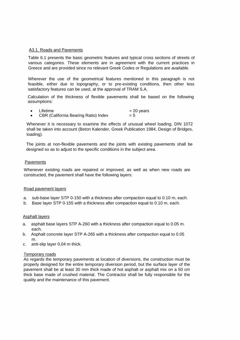
Α3.1. Roads and Pavements
Table 6.1 presents the basic geometric features and typical cross sections of streets of
various categories. These elements are in agreement with the current practices in
Greece and are provided since no relevant Greek Codes or Regulations are available.
Wherever the use of the geometrical features mentioned in this paragraph is not
feasible, either due to topography, or to pre-existing conditions, then other less
satisfactory features can be used, at the approval of TRAM S.A.
Calculation of the thickness of flexible pavements shall be based on the following assumptions:
Lifetime = 20 years CBR (California Bearing Ratio) Index = 5
Whenever it is necessary to examine the effects of unusual wheel loading, DIN 1072
shall be taken into account (Beton Kalender, Greek Publication 1984, Design of Bridges,
loading).
The joints at non-flexible pavements and the joints with existing pavements shall be
designed so as to adjust to the specific conditions in the subject area.
Road pavement layers
Pavements
a. sub-base layer STP 0-150 with a thickness after compaction equal to 0.10 m, each.
b. Base layer STP 0-155 with a thickness after compaction equal to 0.10 m, each.
Asphalt layers
a. asphalt base layers STP Α-260 with a thickness after compaction equal to 0.05 m.
each.
b. Asphalt concrete layer STP Α-265 with a thickness after compaction equal to 0.05
m. c. anti-slip layer 0,04 m thick.
Temporary roads
As regards the temporary pavements at location of diversions, the construction must be
properly designed for the entire temporary diversion period, but the surface layer of the
pavement shall be at least 30 mm thick made of hot asphalt or asphalt mix on a 50 cm
thick base made of crushed material. The Contractor shall be fully responsible for the
quality and the maintenance of this pavement.
Whenever existing roads are repaired or improved, as well as when new roads are
constructed, the pavement shall have the following layers:

Table 6.1 Basic features and geometrical characteristics of urban streets
Characteristics, Geometrical standards
Road category
Freeway Other main arteries Secondary artery Collector road Local road, road to Depot
Trips served Interurban and long
distance urban Long and medium distance urban
Medium distance urban
Short distance urban and access trips
Access trips
Sideroads Yes Often No No No
Median island Always Normally Desirable No No
Median openings Not allowed Allowed Left turn lane required
- -
Design speeds (Km/h) 120 80 70 50 40
Traffic capacity (passenger cars per hour and lane)
1400-1600 800-1000 600-800 300-600 200-400
Number of traffic lanes 4-8 4-8 2-4 2 2
"Occupation width" (meters): (Minimum-
Desirable) 36-60 17-30 10-18 9-15 7-9
Max. longitudinal gradient 4% 5% 6% 12% 15%
Horizontal curve min radius 700 300 200 75 40
Traffic lane width 3,75 3,50 3,50 3,25 2,50-3,00
Parking on the street Not allowed Not allowed Non desirable Allowed Allowed
Bus lines and stops Usually interurban or suburban No stop on the Avenue
Yes. Stops always in recesses
Yes. Desirable to locate stops in a
recess
Ends of Bus lines
No
Intersections
-With local road No connection STOP sign without
discontinuing the median STOP Sign
STOP sign or no sign
Usually no sign
-With collector road No connection STOP sign,
Usually without discontinuing the median
STOP sign STOP sign
-With a secondary artery
Plain level crossing without connections or
grade separated junctions
Signalling STOP sign or
signalling
-With other main arteries Grade separated
junctions
Signalling with directing islands and left turn
lanes
-With a Freeway High standard Grade Separated Junctions

A3.2 Highly-Loaded Road pavement areas The design of highly-loaded road pavement areas will be mainly affected by the maximum values of the structural loads exercised on the road pavement and not by repetitive exercise of lower loads. If specific instructions are not given, then the design will be based on the worst load or on load combinations that may be exercised in the subject highly-loaded area. The analysis of the highly-loaded areas shall be effected using any recognized method for identifying maximum deformation under loading. The maximum deformation shall be less or equal to 2mm. A3.4 Pedestrian Ways – Paved Surfaces Pedestrian ways and other paved surfaces shall be loaded in accordance with DIN 1072. The calculation methods to be utilized shall be as described for highly-loaded areas. Joints shall be properly spaced, in case non-flexible road pavements and stiff material are used. The design shall be based on a 20-year life cycle as well as on a CBR=5. A3.5 Signaling, Horizontal and Vertical Signage The signaling, horizontal and vertical signage design shall be based on the following: “Instructions for Greek Roads‟ Signage”, Ministry of Transport and Public Works, General
Directorate of Public Works, 1960. “Roads Signs”, Ministry of Public Works, General Directorate of Public Works, Traffic
Section (A6), November 1974. “Road Traffic Code”, Law 2696, 1999 (FEK 57A/23.03.1999). “Road Pavement Markins”, Ministry of Public Works, General Directorate of Public Works,
Traffic Section (A6), 1975. “Technical Instructions for the Signage of Typical Road Networks”, Ministry of Public Works,
Traffic and Safety Directorate (Γ2), Traffic Signage (Γ), January 1992. A3.6 Parapets, Traffic barriers Parapets or temporary traffic barriers with containment capacity equal to the capacity of the permanent parapets shall be installed, where necessary, in order to provide protection at the perimeter of the temporary traffic diversions or even protection against any eventual traffic-related risks adjacent to the areas where works are executed. As regards occupation of areas and long-term traffic diversions, decorative and environment-friendly parapets shall be installed, where deemed necessary for reasons of aesthetics. Light fencing shall be installed only in case of short-term area occupation or traffic diversion (of less than one-week duration). A3.7 Curbs, Sidewalks The typical curb shall be 16cm high in accordance with the Standards of the Municipality it crosses. Sidewalks shall also be in accordance with the Standards of the Municipality where the section of the Project belongs – in terms of geography. The curbs shall be constructed on the re-configured sidewalks, as well as on the foreseen traffic isles. The lower part of the road pavement sub-base shall also continue underneath the basis of the curbs.
Energy absorption arrangements (such as traffic barriers for vehicles, pedestrian balustrades etc. or a combination thereof) shall be provided as required, in view of the project completeness and compliance with the safety instructions for pedestrians and vehicles.

A3.8 Sewage network The typical details concerning the rainwater sumps shall comply with the requirements of EYDAP. Rainwater sewage pipes shall be made of prefabricated cement pipes, in line with the specifications of Standard Technical Specifications T. 110, FEK 253/B/84 and Circular E177/12.11.84 of the Ministry of PEHODE/General Secretariat of Public Works. Drains, where foreseen, shall be manufactured in line with the Standard Technical Specifications T. 110. The entire structure intended for collection and drainage of rain water must be waterproofed (i.e., at its outer surface “taking” water of any origin) using appropriate waterproofing materials, so as to prevent water ingress or the presence of moisture. Water at the outer surface of the structure must be collected and discharged directly to the rainwater sump system, regardless of the existence of the respective rainwater sump system of the underground station. The water shall be discharged either in part or in total towards the roads‟ rainwater sump system. Special attention must be drawn to the sensitive parts of the joints, so that even the signs of moisture be completely eliminated from the visible parts of the structure. The water sewage pipes shall be manufactured in accordance with the requirements of this Technical Description. A3.9 Asphalt The supply of the asphalt 80/100 shall be made by the Contractor through the market without any tax exemption. The asphalt shall meet the requirements of the Standard Technical Specifications. Its quality shall be checked either through check certificates, to be issued by the asphalt manufacturing plants and made available by the Contractor or through checks to be performed by TRAM S.A., as stipulated by the Ministry of Public Works Circular No. Γ3/β/οικ./0337/13.02.1970. The Contractor shall be exclusively responsible for checking the quality of the asphalt. One month prior to the commencement of the asphalt works, the Contractor shall submit mix designs for the asphalt-mixes, to be utilized in the subject Project. TRAM S.A., based on the aforesaid mix designs, shall determine the type of the asphalt-mix to be used for each work-phase. The asphalt layer, wherever laid, shall be anti-slip made of pre-coated fine aggregate 9 with p.s.v. > 65 to be spread on the surface of the asphalt layer under construction before its compaction.

PART B
BASIC PARAMETERS FOR THE ALIGNMENT DESIGN OF LINES FOR FIXED ROUTE
MODES OF TRANSPORT RUNING AT A VELOCITY LESS THAN 100 Km/h
B1. GENERAL
The alignment of lines presupposes that the following parameters have been set, namely:
Design Velocity ve
Allowable Longitudinal Inclination
Vehicle Type
Train Length
Daily Tonnage (Tones/ Day)
Type and Location of the Areas to be Utilized
Dimensions regarding the Lines Alignment
Project Construction Organization Chart and Project Development Perspectives
For selecting the design elements sequence and their parameters, relevant threshold values
are taken into consideration (see Table 1-1).
Table 1-1: Determination of design threshold values
Construction limit
Acceptable values Typical value
Threshold value
Values by exception
Value by exception
Absolute minimum value
In general, the following apply:
The threshold acceptable value is set on the basis of the corresponding specifications
and constitutes the minimum acceptable value.
The construction limit concerns the construction capacity of a value, as well as the
possibility for this value to be maintained in the future through project maintenance. The
construction limit concerns the maximum limit of a parameter.
The range of the values by exception concerns values which apply in exceptional cases
subject documentation and approval by the Service.
Generally, typical values must be selected as parameter values.
Frequent alternation of the design elements must be avoided. The minimum length of a
straight line or of a total arc, that must correspond to a running length of approximately
1.5 sec, is
L = 0.4 • ν, where L expressed in m and ν expressed in [km/h]
The values for balanced cant and the circular arc radius are presented in Table 1-2.
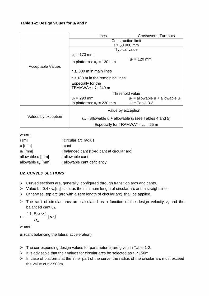
Table 1-2: Design values for u0 and r
Lines Ι Crossovers, Turnouts
Construction limit r ≤ 30 000 mm Typical value
u0 = 170 mm
Ι u0 = 120 mm
Acceptable Values
In platforms: u0 = 130 mm
r 300 m in main lines
r 180 m in the remaining lines σπόλοιπες γραμμές
Especially for the ΤRΑΜWAY r 240 m
Threshold value
u0 = 290 mm Ι u0 = allowable u + allowable uf
In platforms: u0 = 230 mm see Table 3-3
Values by exception
Value by exception
u0 = allowable u + allowable uf (see Tables 4 and 5)
Especially for ΤRΑΜWAY rmin = 25 m
where:
r [m] : circular arc radius
u [mm] : cant
u0 [mm] : balanced cant (fixed cant at circular arc)
allowable u [mm] : allowable cant
allowable ug [mm] : allowable cant deficiency
B2. CURVED SECTIONS
Curved sections are, generally, configured through transition arcs and cants.
Value L= 0.4 · ve [m] is set as the minimum length of circular arc and a straight line.
Otherwise, top arc (arc with a zero length of circular arc) shall be applied.
The radii of circular arcs are calculated as a function of the design velocity ve and the
balanced cant u0.
r = ][8.11
0
2
mu
ve
where:
u0 (cant balancing the lateral acceleration)
The corresponding design values for parameter u0 are given in Table 1-2.
It is advisable that the r values for circular arcs be selected as r 150m.
In case of platforms at the inner part of the curve, the radius of the circular arc must exceed
the value of r 500m.

B3. CANT
Cants are configured by lifting the outer rail through cant ramps.
A uniform cant is maintained in canistroeid curves on condition that the typical values of the
cants in individual circular arcs do not differ between them significantly.
Cants are rounded up in values divided by 5.
The cant design values are given in Table 3-1.
Table 3-1: Design values for outer rail cant (u)
Acceptable Values
Lines Crossovers, Turnouts
Construction limit
u = 20mm
Typical value
u = 100m
in platforms: u = 60mm
Especially in TRAMWAY:
u = 0 mm
u = 60 mm
Especially in TRAMWAY:
u = 0 mm
Threshold values
Ballasted superstructure:
allowable u = 160 mm
Fixed roadway: allowable
u = 160mm
In platforms = allowable u
= 100 m
Especially in TRAMWAY:
allow. u = 150 (165) mm
allowable u = 120 mm
V - Crossover without
movable parts
allowable u = 100 mm
Values by exception Values by exception
160 < allowable u ≤ 180
mm
170 < allowable u ≤ 180
mm
120 < allowable u ≤ 150
mm
100 < allowable u ≤ 130
mm
Absolute minimum value
allowable u > 180 mm
Table 3-2: Design values for uf
Acceptable Values
Lines Crossovers, Turnouts
Construction limit
Typical value
uf = 70 mm uf = 60 mm
Threshold values
allowable uf = 130 mm
allowable uf = 120 mm in
line with Table 3-3
Values by exception
Values by exception
150 < allowable uf allowable uf ≤ 150 mm in
line with Table 3-3
Absolute minimum value

- allowable uf in line with
Table 3-3 with an increase
of 20%
In arcs with a radius r < 300m, the maximum value of cant is:
allowable u = 5.1
50r
where:
r [m] : radius
u [mm] : cant
In curved sections, stations and sections where frequent stops, the value of the cant shall
be selected between the minimum value and the typical value (reg u).
reg u = r
ve
21.7
where:
r [m] : radius
u [mm] : cant
In sections with uniform speed, the value of the cant shall be selected between the typical
value (reg u) and the balanced cant u0.
Balanced cant u0 equals to:
u0 = r
ve
28.11
where:
r [m] : radius
u [mm] : cant
The cant deficiency uf is set as follows:
uf = u0- u where: u = the selected or existing cant. The minimum cant value equals to:
min u = r
ve
28.11- allowable uf
B4. TRANSITION ARCS
The Transition arcs are required when the difference of the cant deficiency values between
two design items Γuf is in general:
Γuf 40 mm
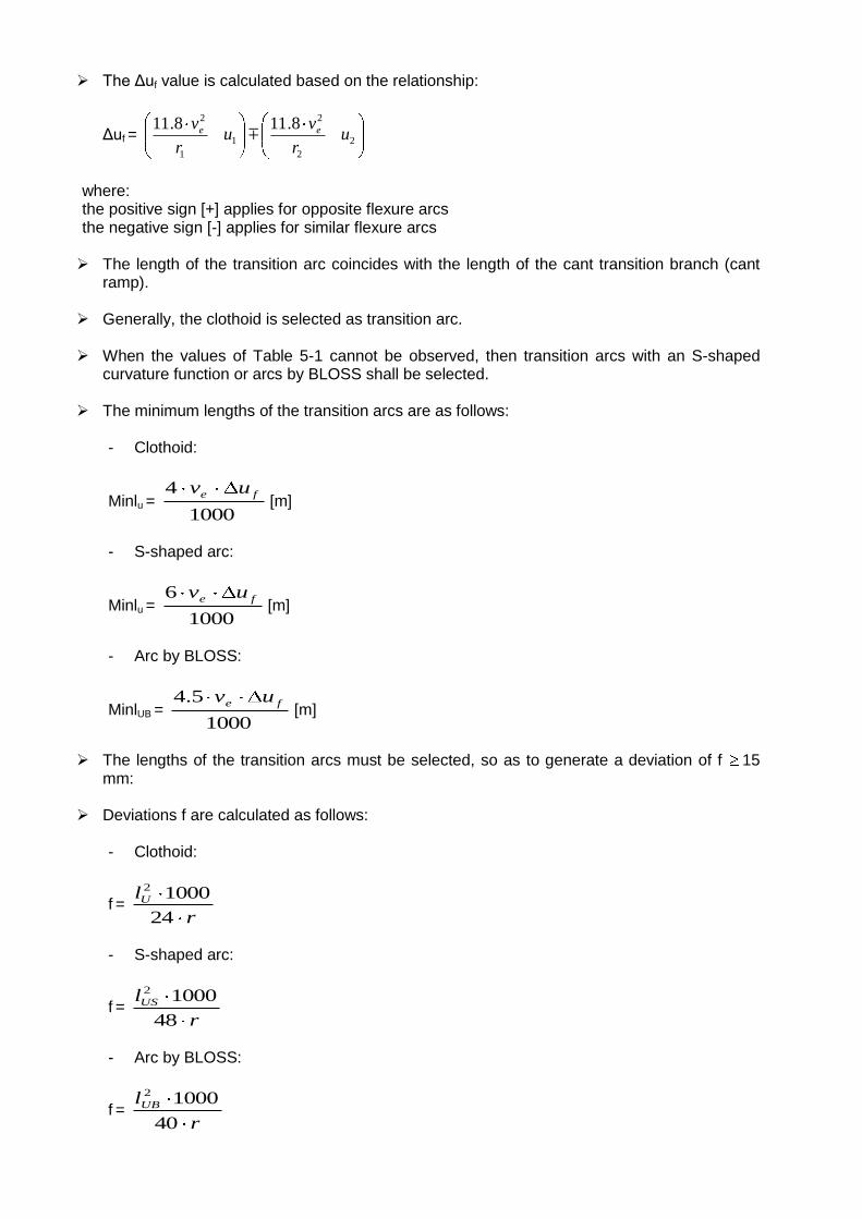
The Γuf value is calculated based on the relationship:
Γuf = 2
2
2
1
1
2 8.118.11u
r
vu
r
v ee
where: the positive sign [+] applies for opposite flexure arcs the negative sign [-] applies for similar flexure arcs The length of the transition arc coincides with the length of the cant transition branch (cant
ramp). Generally, the clothoid is selected as transition arc. When the values of Table 5-1 cannot be observed, then transition arcs with an S-shaped
curvature function or arcs by BLOSS shall be selected. The minimum lengths of the transition arcs are as follows:
- Clothoid:
Minlu = 1000
4 fe uv[m]
- S-shaped arc:
Minlu = 1000
6 fe uv[m]
- Arc by BLOSS:
MinlUB = 1000
5.4 fe uv[m]
The lengths of the transition arcs must be selected, so as to generate a deviation of f 15
mm: Deviations f are calculated as follows:
- Clothoid:
f = r
lU
24
10002
- S-shaped arc:
f = r
lUS
48
10002
- Arc by BLOSS:
f = r
lUB
40
10002
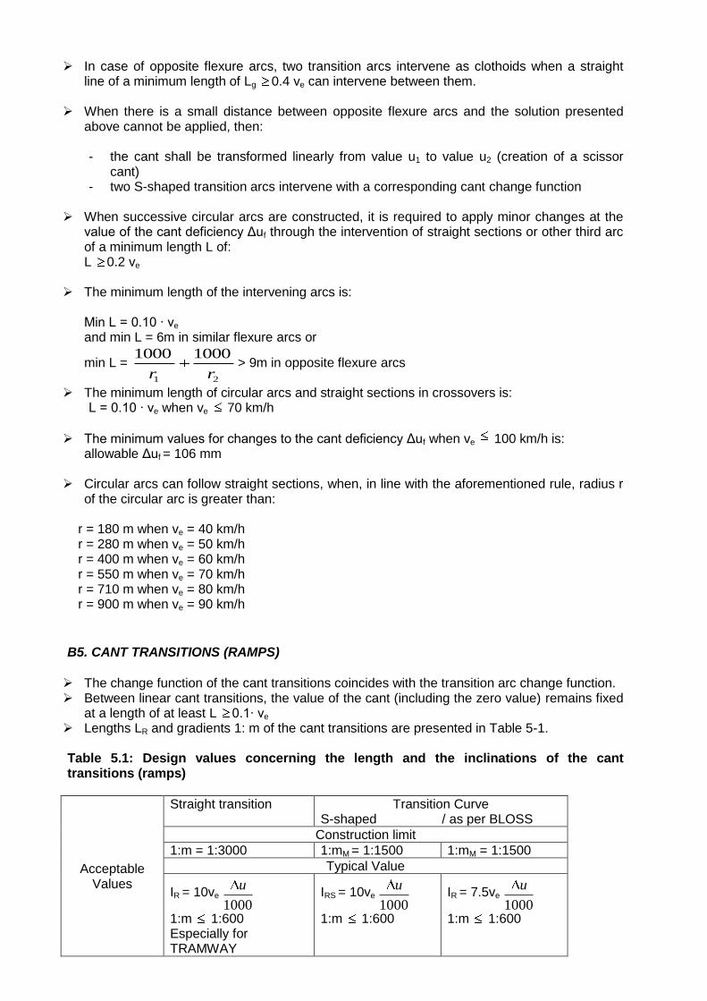
In case of opposite flexure arcs, two transition arcs intervene as clothoids when a straight
line of a minimum length of Lg 0.4 ve can intervene between them. When there is a small distance between opposite flexure arcs and the solution presented
above cannot be applied, then:
- the cant shall be transformed linearly from value u1 to value u2 (creation of a scissor cant)
- two S-shaped transition arcs intervene with a corresponding cant change function
When successive circular arcs are constructed, it is required to apply minor changes at the value of the cant deficiency Γuf through the intervention of straight sections or other third arc of a minimum length L of: L 0.2 ve
The minimum length of the intervening arcs is:
Min L = 0.10 · ve
and min L = 6m in similar flexure arcs or
min L = 21
10001000
rr> 9m in opposite flexure arcs
The minimum length of circular arcs and straight sections in crossovers is: L = 0.10 · ve when ve 70 km/h
The minimum values for changes to the cant deficiency Γuf when ve 100 km/h is: allowable Γuf = 106 mm
Circular arcs can follow straight sections, when, in line with the aforementioned rule, radius r of the circular arc is greater than:
r = 180 m when ve = 40 km/h r = 280 m when ve = 50 km/h r = 400 m when ve = 60 km/h r = 550 m when ve = 70 km/h r = 710 m when ve = 80 km/h r = 900 m when ve = 90 km/h
B5. CANT TRANSITIONS (RAMPS)
The change function of the cant transitions coincides with the transition arc change function. Between linear cant transitions, the value of the cant (including the zero value) remains fixed
at a length of at least L 0.1· ve Lengths LR and gradients 1: m of the cant transitions are presented in Table 5-1. Table 5.1: Design values concerning the length and the inclinations of the cant transitions (ramps)
Acceptable Values
Straight transition Transition Curve S-shaped / as per BLOSS
Construction limit
1:m = 1:3000 1:mM = 1:1500 1:mM = 1:1500
Typical Value
IR = 10ve
1000
u
1:m 1:600 Especially for TRAMWAY
IRS = 10ve
1000
u
1:m 1:600
IR = 7.5ve
1000
u
1:m 1:600

IR = 6ve
1000
u
1:m 1:300
Threshold value
IR = 8ve
1000
u
1:m 1:400
IRS = 10ve
1000
u
1:m 1:600
IRB = 6ve
1000
u
1:m 1:400
Values by exception
Values by exception
8ve
1000
u> IR 6
1:m 1:400
- - - -
Absolute minimum value
6ve
1000
u> IR 5
1:m 1:400
- - - -
B6. LONGITUDINAL PROFILES
In TRAMWAY lines and in secondary lines, the maximum longitudinal gradient is 40‰ at absolute maximum inclination in critical sections of a limited length of 90‰.
Rounding arcs are applied at the longitudinal profile when the change of the values of the longitudinal gradients is:
ΓI 1‰
The minimum length of the rounding arc is set at:
La 20 m
minimum vertical radius: ra = 0.4 · v 2
e 650 at crossovers minra = 5000 m
where: ra [m] ve [km/h] The design values of the vertical rounding arc are given in Table 6-1. Table 6-1: Design values of rounding arc radius ra at longitudinal profiles
Acceptable Values
Construction limit ra 30 000 m
Typical value
ra 0.4 · v2
e [m]
Threshold value
ra 0.25 · v2
e [m]
ra 2 000 m
Values by exception
Value by exception
ra = 0.16 · v2
e [m] in curved sections of
curves
ra = 0.13 · v2
e [m] in hollow curves
ra 2 000 m

Absolute minimum value - -
B7. DETERMINATION OF MAXIMUM ALLOWABLE SPEED DUE TO TRACK ALIGNMENT
The constructed geometrical dimensions of a line‟s alignment determine the maximum allowable speed for fixed-route modes of transport passing a curve. In general, with regard to the speed when passing a curve, further to the consent of the Project Management Division, the following general principles can be kept, namely:
a. The maximum allowable velocity deriving from the existing cant deficiency can be rounded up to 1%.
b. The minimum lengths of the transition arcs can be reduced by 20%. c. Linear cant transitions are permitted up to lengths:
LR = 6 · ve · 1000
u
or 1:m = 1:400 d. The allowable limits for change of the cant deficiency Γu can be increased by 20%. With regard to fixed-route transport modes with body inclination technology, the following threshold values apply:
In curve arcs without obligatory points, the cant deficiency may range up to 300 mm: uf 300 mm
In arcs with crossovers or obligatory points, the cant deficiency cannot be greater than 150 mm
uf 150 mm In transition cants, as regards the velocity vN of vehicles with body inclination technology, the
following apply: a. in case of linear cants change, then:
LR = 6 · vN · 1000
u (1: m 1:400)
b. in case of parabolic cant change (s-shaped), then:
LRS = 8 · vN · 1000
u (1: m 1:400)
c. in case of arcs per BLOSS:
LRB = 9 · vN · 1000
u (1: m 1:400)
The relations for calculating the maximum allowable velocity max v [km/h] for vehicles passing a curve on the basis of design data are given in Table 7-1. The lower value resulting from the calculated values should be always taken into consideration. Table 7.1: Maximum Allowable Velocity
S/N Criterion Maximum Allowable Velocity Max v [km/h]
Reference
1 Cant deficiency ).(
8,11fuallowu
r
allow. uf
Table 3-2
2 Change of curvature in successive arcs allow. Γuf = 106 mm
Case: Straight Sections – Circular Arcs
fuallowr
.8,11
Case: Successive opposite or
Chapter B4
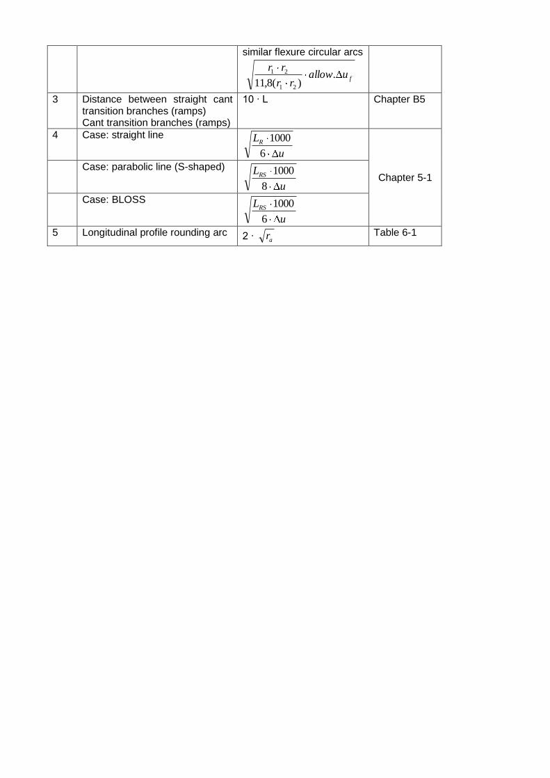
similar flexure circular arcs
fuallowrr
rr.
)(8,11 21
21
3 Distance between straight cant transition branches (ramps) Cant transition branches (ramps)
10 · L Chapter B5
4 Case: straight line
u
LR
6
1000
Chapter 5-1 Case: parabolic line (S-shaped)
u
LRS
8
1000
Case: BLOSS
u
LRS
6
1000
5 Longitudinal profile rounding arc 2 · ar Table 6-1