Embed Size (px)
Citation preview

~
bandpassfilter
lowpass filter
ramp generator
Y axis
X axis
RF
LO
RBW VBW
Basic parameters and functions of an analog spectrum analyzer
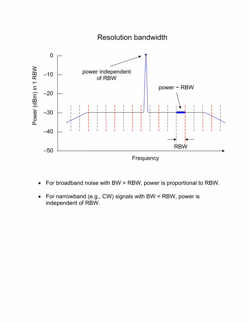
• For broadband noise with BW > RBW, power is proportional to RBW. • For narrowband (e.g., CW) signals with BW < RBW, power is
independent of RBW.
RBW Frequency
0
–10
–20
–30
–40
–50
Pow
er (d
Bm
) in
1 R
BW
Resolution bandwidth
power ~ RBW
power independent of RBW

Detector types in digital spectrum analyzers
Most modern spectrum analyzers use LCDs to display spectra, rather than the CRTs of older (purely analog) analyzers. With LCDs, the display resolution in both frequency and power is more limited. The finite number of pixels in an LCD (as opposed to the effectively infinite number for a CRT) means that, for wide frequency spans and narrow RBWs, each pixel has to represent the spectral information for many sample points that lie within the frequency span of the pixel. It is left to the user to select which point to display in each pixel. Typical options include:
• Max peak (or simply peak) – the sample with the maximum power • Min peak – the sample with the minimum power • Sample – a “typical” value, usually either the first (in frequency) or
central sample for each pixel • RMS – power corresponding to the square of the RMS (root-mean-
square) voltage magnitude of the samples for each pixel • Average – power corresponding to the average mean voltage
magnitude of the samples
From Fundamentals of Spectrum Analysis by Christoph Rauscher, Rohde & Schwarz, 2007

Which detector type to use depends on the nature of the signal.
• In the presence of narrowband signals, max peak ensures that no signal is missed.
• When only broadband, noise-like signals are present, sample, RMS, or average detection better represents the spectrum than does max peak, which will show the upper envelope of the spread in power.
From Agilent Application Note 150: Spectrum Analysis Basics

RFI-rich spectrum using peak (top) & sample (bottom) detection


Example: Ripple in IF power spectrum due to multiple reflections over 0.7-meter and 5-meter cable lengths.

[ mod(t) = 0 ]

• Phase noise of a carrier = total power in two modulation sidebands • RMS phase jitter of a carrier in radians = sqrt [ (power in 2 sidebands) / (power in carrier) ]
Example: Calculate carrier phase noise for spectrum above, out to the “knees” in the spectrum
Phase noise level is -30 dBm/RBW out to 6 RBWs away from carrier.
→ power in 2 sidebands = 2 x (0.001 mW / RBW) x (6 RBW) = 0.012 mW In practice, power is usually calculated from frequency span & RBW. For example, if span = 12 kHz and RBW = 1 kHz, power in 2 sidebands = (0.001 mW / 1 kHz) x (12 kHz) = 0.012 mW Power in carrier = 0 dBm = 1 mW RMS phase jitter of carrier = sqrt [ 0.012 mW / 1 mW ] radian = 0.11 radian = 6 degrees
RBW Frequency
0
–10
–20
–30
–40
–50
Pow
er (d
Bm
) in
1 R
BW
Measuring carrier phase noise


Measure the strength of phase cal relative to system noise in two ways: 1. Measure height of phase cal tone relative to broadband system noise
with a narrow RBW. Typically phase cal is about 30 dB above noise with a 10-Hz RBW. From this measurement, calculate ratio of phase cal tone power to system power over a 1-MHz bandwidth. Value should be approximately –20 dB, i.e., phase cal is ~1% of total system power.
2. Using total power detector, measure change in baseband power level as phase cal is turned on and off.
Compare the estimates of the pcal/system power ratio from the 2 methods. If the first ratio is smaller than the second ratio by >1 dB, phase cal power is probably being lost to modulation sidebands, which might not otherwise be easily observed due to their unknown frequency range and structure.
Frequency
0
–10
–20
–30
–40
–50
Pow
er (d
Bm
) in
1 R
BW
Indirect detection of severe phase cal modulation
−60 8-MHz-wide baseband spectrum with phase cal tones with modulation sidebands – spectrum measured with 10 Hz RBW
Same spectrum as below but measured with 1 MHz RBW –
phase cal tones not visible
8 MHz
1 MHz