Embed Size (px)
Citation preview

Tele Radio Panther
BASIC INSTALLATION INSTRUCTIONS
IM-PN-RX001-A01-EN
ARTICLE CODE: PN-R8-1, PN-R8-2, PN-R8-6, PN-T7-3, PN-T7-4, PN-T7-5.
LANGUAGE: ENGLISH (ORIGINAL)
Standard settings

Thank you for purchasing a Tele Radio product PN-R8-1, PN-R8-2, PN-R8-6, PN-T7-3, PN-T7-4, PN-T7-5
INSTALLATION INSTRUCTIONS FOR DOWNLOAD: www.tele-radio.com
READ ALL INSTRUCTIONS CAREFULLY BEFORE MOUNTING, INSTALLING AND CONFIGURATING THE PRODUCT.
These instructions are published by Tele Radio AB without any guarantee. These instructions are solely directed towards qualified installers. The instructions may be removed or revised by Tele radio AB at any time and without any further notice. Corrections and additions will be added to the updated versions of the instructions.
The instructions that contain information on the installation and configuration of the remote radio control unit on the machine are not intended to be passed on to the end user. Only such information may be passed on to the end user, that is needed to operate the machine correctly by radio remote control.
Tele Radio AB products are covered by a guarantee against material, construction or manufacturing faults. During the guarantee period, Tele Radio AB may replace the product or faulty parts with new. Work under guarantee must be carried out by Tele Radio AB or by an authorized service centre specified by Tele Radio AB. Make sure that repairs and maintenance are only carried out by qualified personnel. Use only spare parts from Tele Radio AB. Contact your Tele Radio representative if you need service or support. The EC declaration of conformity can be downloaded from our website.
©Tele Radio AB, 2011
TELE RADIO ABDatavägen 21, SE-436 32 Askim. Sweden Tel: +46-31-748 54 60 Fax: +46-31-68 54 64 www.tele-radio.com

3Contents
CONTENTS
TECHNICAL DATA RECEIVER 4 R8-1 (BASE BOARD) 4 R8-6 (BASE + RELAY EXPANSION BOARD) 5 R8-2 (BASE + HIGH VOLTAGE EXPANSION BOARD) 6
CURRENT CONSUMPTION 7
TECHNICAL DATA TRANSMITTER 8 3-BUTTONS TRANSMITTER T7-5 8 6-BUTTONS TRANSMITTER T7-4 9
8-BUTTONS TRANSMITTER T7-3 10
RECEIVER LED INDICATIONS 11 LED INDICATIONS DURING START UP 11 LED INDICATIONS IN PROGRAMMING MODE 11 LED INDICATIONS DURING OPERATION 12 ERROR INDICATIONS ON LEDS 12
STANDARD SETTINGS 13 START THE TRANSMITTER 13 TURN THE TRANSMITTER OFF 13 REGISTER THE TRANSMITTER IN THE RECEIVER 13 ERASE ALL TRANSMITTERS FROM THE RECEIVER 13 RELAY SETTINGS 14 OTHER RELAY SETTINGS 15
IC AND FCC INFORMATION 16
BATTERY PRECAUTIONS 18 DISPOSAL OF BATTERIES AND ELECTRONICS 18 ROHS AND WEEE 19
GUARANTEE, SERVICE, REPAIRS AND MAINTENANCE 19

4
18
19
20
LED7 LED8
LED6
LED9
LED10
F
S
Relay 5 Relay 1 Relay 3Relay 2 Relay 4
5 1 2 3 4
+ -12-24 V DC
CO NO NC
WR/5 CO NO NC
1 (on/off)
CO NO NC
2CO NO NC
3 (kill)
CO NO NC
4 (Buzzer)
1 2 3 4 5 6 7 8 9 10 11 12 13 14 15 16 17
LEDs
TECHNICAL DATA RECEIVERR8-1 (BASE BOARD)
1. Relay 1- on/off relay2. Relay 5- working relay3. Relay 24. Relay 3- kill relay5. Relay 4- buzzer relay6. Power supply connection 6-30 V DC7. Relay LED 58. Relay LED 19. Relay LED 210. Relay LED 311. Relay LED 4
12. Power supply LED 613. Trabus programming connector14. Terminal block for RS23215. Function button (Cancel) 16. Select button (OK)17. LED 818. LED 919. LED 1020. LED 7
12345
6
7 8 9 10 11 1312
14151617181920

5
R8-6 (BASE + RELAY EXPANSION BOARD)
21. LED 12- communication with the base board 22. Relay LED 623. Relay LED 724. Relay LED 825. Relay LED 926. Relay LED 1027. Relay LED 1128. Relay 629. Relay 730. Relay 8
31. Relay 932. Relay 1033. Relay 1134. Trabus programming connector
18
19
20
LED7 LED8
LED6
LED9
LED10
F
S
Relay 5 Relay 1 Relay 3Relay 2 Relay 4
5 1 2 3 4
+ -12-24 V DC
CO NO NC
WR/5 CO NO NC
1 (on/off)
CO NO NC
2CO NO NC
3 (kill)
CO NO NC
4 (Buzzer)
1 2 3 4 5 6 7 8 9 10 11 12 13 14 15 16 17
LEDs
Relay 6 Relay 7 Relay 8 Relay 10Relay 9 Relay 11
LEDLED6LED7LED8LED9LED10LED11
21 22 23 24 25 26 27 28 29 30 31 32 33 34 35 36 37 38 39
CO NO NC CO CO NO NC CO NO NC CO NO NC CO NO NC CO NO NC 6 7 8 9 10 11
21
28 29 30 31 32 3334
222324252627

6
18
19
20
LED7 LED8
LED6
LED9
LED10
F
S
Relay 5 Relay 1 Relay 3Relay 2 Relay 4
5 1 2 3 4
+ -12-24 V DC
CO NO NC
WR/5 CO NO NC
1 (on/off)
CO NO NC
2CO NO NC
3 (kill)
CO NO NC
4 (Buzzer)
1 2 3 4 5 6 7 8 9 10 11 12 13 14 15 16 17
LEDs
21 22 23 24
COM
MO
N
24-1
10 V
AC
230
V AC
LED
R8-2 (BASE + HIGH VOLTAGE EXPANSION BOARD)
2221 23 24
COMMON 24-110 V AC 230 V AC
35
35. Power supply LED

7
Current consumption
RX MODEL SUPPLY VOLTAGE MAX. CURRENT CONSUMPTION
R8-1 12-24 V DC <200 mA.
R8-2 24-230 V AC <200 mA.
R8-6 12-24 V DC <300 mA.
Technical data
FUNCTIONAL RELAYS: 5/ 11 potential free* functional relays makes/ breaks 8A ACINUMBER OF CHANNELS: 16 SIZE: 120 x 116 x 50 mm./ 4.7” x 4.6” x 2”WEIGHT: 400-500 grams/ 14-18 oz. IP CLASS: IP66 FREQUENCY: 2405-2480 MHz.
* Potential free means that you must you need to supply voltage to get power out of a relay (e.g. via a connection comb).
8
17 18 19
321
1st step
2nd step
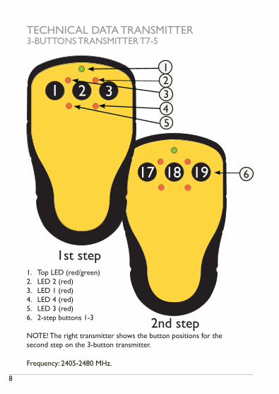
TECHNICAL DATA TRANSMITTER3-BUTTONS TRANSMITTER T7-5
1. Top LED (red/green)2. LED 2 (red)3. LED 1 (red)4. LED 4 (red)5. LED 3 (red)6. 2-step buttons 1-3
NOTE! The right transmitter shows the button positions for the second step on the 3-button transmitter.
123
6
Frequency: 2405-2480 MHz.
45

9
222120
17 18 19
654
321
1st step
2nd step
6-BUTTONS TRANSMITTER T7-4
1. Top LED (red/green)2. LED 2 (red)3. LED 1 (red)4. LED 4 (red)5. LED 3 (red)6. 2-step buttons 1-6
NOTE! The right transmitter shows the button positions for the second step on the 6-button transmitter.
12345
6
Frequency: 2405-2480 MHz.

10
8-BUTTONS TRANSMITTER T7-3
1. Top LED (red/green)2. LED 2 (red)3. LED 1 (red)4. LED 4 (red)5. LED 3 (red)6. 2-step buttons 1-8
NOTE! The right transmitter shows the button positions for the second step on the 8-button transmitter.
2423
222120
17 18 19
7 8
654
321
1st step
2nd step
12345
6
Frequency: 2405-2480 MHz.

11
LED INDICATIONS
LED INDICATIONS DURING START UP1. All receiver LEDs lit up for 0.5 sec. to show that they are working.
2. Current settings are shown for 2 sec.
On relay LEDs 1-4:
Relay LED 1 OFF Continuous transmitting mode
ON Discontinuous transmitting mode
Relay LED 2 OFF Custom ID not enabled
ON Custom ID enabled
Relay LED 3 OFF Configuration ID not enabled
ON Configuration ID enabled
Relay LED 4 OFF Frequency scan on
ON Frequency scan off (fixed frequency)
On LED 7, 8 and 9:
LED 7 ON Operating mode 1
LED 8 ON Operating mode 2
LED 9 ON Operating mode 3
LED INDICATIONS IN PROGRAMMING MODELED 7 red ON
LED 8 yellow ON
LED 9 green ON
LED 10 orange ON

12
LED INDICATIONS DURING OPERATIONLED 6 red ON Power to the receiver is on
OFF Power to the receiver is off
LED 7 red OFF No transmitter registered
flashes (slow) At least one transmitter is registered and one transmitter is logged in, but not transmitting.
flashes (quick) At least one transmitter is registered, but not transmitting.
ON Valid radio packages from a registered transmitter received.
ERROR INDICATIONS ON LEDSLED 7 (red)
+ LED 8(yellow)
ON Reading of production data failed. Contact your representative.
LED 7 (red)
ON Radio module startup failed. Contact your representative.
LED 8 ON A radio package not coming from a Panther transmitter is received.
LED 8 + LED 9 ON A radio package from a transmitter in a different mode (discontinuous or continuous) than the receiver is received.
LED 8 + LED 10 ON A radio package is received from a transmitter that is not registered.
LED 9 ON A radio package is received, but the radio signal strength (RSSI) is too low.
LED 10
ON A radio package is received, but the configuration ID is not accepted.

13
STANDARD SETTINGS
• discontinuous radiotransmission• no on/off function
The system will start transmitting as soon as the batteries are inserted and a transmitter button is pressed. Radio transmission will end when no transmitter button is being pressed.
DEFAULT STATE
START THE TRANSMITTER
TURN THE TRANSMITTER OFF
1. Start the transmitter by pressing any transmitter button.
1. The transmitter turns off when no transmitter button is pressed.
1. Press the receiver Function button and the Select button at the same time until red LED 1-5 go out.
NOTE! If red LED 7 flashes slowly, one or several transmitters are still registered in the receiver.
REGISTER THE TRANSMITTER IN THE RECEIVER
ERASE ALL TRANSMITTERS FROM THE RECEIVER
1. Press the receiver Function button until red LED 7 lights up.2. Press the receiver Select button until LEDs 1-5 light. 3. Press any transmitter button, e.g. button 1 until LEDs 1-10 flash 3
times before going out.
14
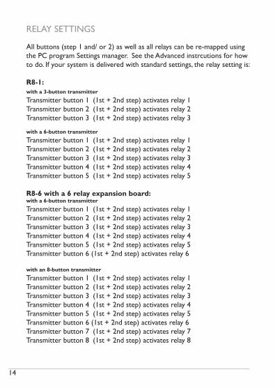
All buttons (step 1 and/ or 2) as well as all relays can be re-mapped using the PC program Settings manager. See the Advanced instrcutions for how to do. If your system is delivered with standard settings, the relay setting is:
R8-1:with a 3-button transmitter
Transmitter button 1 (1st + 2nd step) activates relay 1Transmitter button 2 (1st + 2nd step) activates relay 2Transmitter button 3 (1st + 2nd step) activates relay 3
with a 6-button transmitter
Transmitter button 1 (1st + 2nd step) activates relay 1Transmitter button 2 (1st + 2nd step) activates relay 2Transmitter button 3 (1st + 2nd step) activates relay 3Transmitter button 4 (1st + 2nd step) activates relay 4Transmitter button 5 (1st + 2nd step) activates relay 5
R8-6 with a 6 relay expansion board:with a 6-button transmitter
Transmitter button 1 (1st + 2nd step) activates relay 1Transmitter button 2 (1st + 2nd step) activates relay 2Transmitter button 3 (1st + 2nd step) activates relay 3Transmitter button 4 (1st + 2nd step) activates relay 4Transmitter button 5 (1st + 2nd step) activates relay 5Transmitter button 6 (1st + 2nd step) activates relay 6
with an 8-button transmitter
Transmitter button 1 (1st + 2nd step) activates relay 1Transmitter button 2 (1st + 2nd step) activates relay 2Transmitter button 3 (1st + 2nd step) activates relay 3Transmitter button 4 (1st + 2nd step) activates relay 4Transmitter button 5 (1st + 2nd step) activates relay 5Transmitter button 6 (1st + 2nd step) activates relay 6Transmitter button 7 (1st + 2nd step) activates relay 7Transmitter button 8 (1st + 2nd step) activates relay 8
RELAY SETTINGS

15
OTHER RELAY SETTINGS
• No interlocking• No toggling

16
PLACEMENT OF LABELS WITH IC ANDFCC INFORMATION
1. Product label
The product label is placed under the clip on the battery lid. Remove the clip (2 screws).
1.
Pb
Model: T00007-03Freq.: 2405-2480MHz Sn.:XXXXXX
www.tele-radio.com
2150Pb
Model: T00007-04Freq.: 2405-2480MHz Sn.:XXXXXX
www.tele-radio.com
2150Pb
Model: T00007-05Freq.: 2405-2480MHz Sn.:XXXXXX
www.tele-radio.com
2150
Pb
Mo
del: T00007-05
Freq.: 2405-2480M
Hz
Sn.:X
XX
XX
X
ww
w.tele-radio.com
2150

17
FCC STATEMENTS
THIS DEVICE COMPLIES WITH PART 15 OF THE FCC RULES. OPERATION IS SUBJECT TO THE FOLLOWING TWO CONDITIONS: 1. THIS DEVICE MAY NOT CAUSE HARMFUL INTERFERENCE
2. THIS DEVICE MUST ACCEPT ANY INTERFERENCE THAT MAY CAUSE UNDESIRED OPERATION. NOTE: THE MANUFACTURER IS NOT RESPONSIBLE FOR ANY RADIO OR TV INTERFERENCE CAUSED BY UNAUTHORIZED MODIFICATIONS TO THIS EQUIPMENT. SUCH MODIFICATIONS COULD VOID THE USER´S AUTHORITY TO OPERATE THE EQUIPMENT.
The IC and FCC ID label is placed in the battery compartment on the left side of the batteries. Remove the clip (2 screws) and the battery lid (2 screws).
FCC
ID: O
NFC
0911
AIC
: 480
7A-C
0911
AM
odel
: T00
007-
05
FCC
ID: O
NFC
0911
AIC
: 480
7A-C
0911
AM
odel
: T00
007-
03
FCC
ID: O
NFC
0911
AIC
: 480
7A-C
0911
AM
odel
: T00
007-
04
2.
2. IC and FCC ID label

18
BATTERY PRECAUTIONS
Observe the following general battery warnings.
• As batteries contains flammable substances such as lithium or other organic solvents, they may cause heating, rupture or ignition.
• Risk of explosion if battery is replaced with a bat-tery of an incorrect type.
• Do not short circuit, disassemble, deform or heat batteries.
• Never try to charge a visibly damaged or frozen battery.
• Keep batteries out of reach of small children. Should a child swallow a battery, consult a physician immediately.
• Avoid direct soldering to batteries.
• When discarding batteries, insulate the + and - terminals of batteries with insulating/ masking tape. Do not put multiple batteries in the same plastic bag.
• When improperly disposed, lithium batteries may short circuit, causing them to become hot, burst or ignite.
• Store in a cool location. Keep batteries away from direct sunlight, high temperature, and high humidity.
• Do not throw batteries into fire.
DISPOSAL OF BATTERIES ANDELECTRONICS
Improperly disposed electronics may harm public health and the environ-ment. Batteries and electronic waste may contain toxic heavy metals. If thrown away in the trash, the toxic compounds can leach into soil and water, pollute lakes and streams, making them unfit for drinking, swimming, fishing, and wildlife. Contact your local government’s recycling or solid waste department for more information on proper disposal of
electronics in your region.
!

19
ROHS AND WEEE
In accordance with Directive 2002/95/EC on restriction of the use of certain hazardous substances in electrical and electronic equipment (RoHS) and Directive 2002/96/EC on waste electrical and electronic equipment (WEEE), Tele Radio strives to minimize the use of hazardous materials, promotes reuse and recycling, and reduces emissions to air, soil and water. When a commercially viable alternative is available, Tele Radio strives to restrict or eliminate substances and materials that pose an environmental, health or safety risk.
GUARANTEE, SERVICE, REPAIRS AND MAINTENANCE
The Tele Radio products are covered by a guarantee against material, construction and manufacturing faults. During the guarantee period, Tele Radio may replace the product or faulty parts. Work under guarantee must be carried out by Tele Radio or by an authorized service centre specified by Tele Radio. This is not covered by the guarantee: Faults resulting from normal wear and tear. Parts of a consumable nature. Products that have been subject to unauthorized modifications. Faults resulting from incorrect installation and use. Damp and water damage. Repairs and maintenance must be carried out by qualified personnel. Use spare parts from Tele Radio only. Contact your representative or Helpdesk if you require service or other assistance. Keep the product in a dry, clean place. Keep contacts and antennas clean. Wipe off dust using a slightly damp, clean cloth. Never use cleaning solutions or high-pressure water.

TELE RADIO SVERIGESwedenTel. +46 (0)31-724 98 00e-mail: [email protected]
TELE RADIO GmbHGermanyTel. +49 (0)94 51-944 8 550e-mail: [email protected]
TELE RADIO ASIAChinaTel. +86-(0)592-3111168e-mail: [email protected]
TELE RADIO TURKEYTurkeyTel. +90 216 574 22 94e-mail: [email protected]
TELE RADIO LTDEnglandTel. +44 (0) 1625 509125e-mail: [email protected]
TELE RADIO LLCNorth America & Latin AmericaTel. +1 (305) 459 0763e-mail: [email protected]
TELE RADIO BVBeneluxTel. +31-(0)70-419 41 20e-mail: [email protected]
TELE RADIO ASNorwayTel. +47-6933 4900e-mail: [email protected]
TELE RADIO ABSweden, Main officeTel. +46 (0)31-748 54 60e-mail: [email protected]
www.tele-radio.com