Embed Size (px)
Citation preview


C H A P T E R 3
Basic IPsec VPN Topologies and Configurations
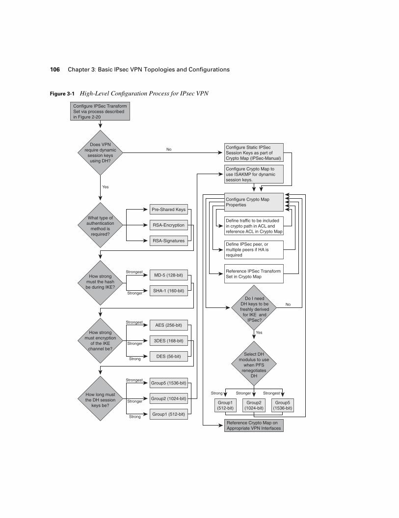
In this chapter, we will review several common deployments of IPsec virtual private networks (VPNs). We will begin by reviewing the typical site-to-site IPsec model over a dedicated circuit between two endpoints, then discuss some of the design implications as that dedicated circuit grows to include an entire routed domain. We will discuss aggregation of many site-to-site IPsec VPNs at an aggregation point, or hub IPsec router, in a standard hub-and-spoke design and extend the IPsec aggregation concept to include Remote Access VPN (RAVPN) design considerations. Figure 3-1 illustrates a loose process that may be helpful when configuring a crypto endpoint for basic IPsec operations. Though effective IPsec VPN design drives the complexity of configuration far beyond what is depicted in Figure 3-1, most of the basic topologies we will discuss will relate to this procedure on a fundamental level.
Each of the following deployments requires the configuration of IPsec in a point-to-point fashion in one way or another. As such, all of the topologies discussed share common configuration tasks to establish the IPsec tunnel:
Step 1 Decide how strong the IPsec transform must be and what mode the tunnel must use (define IPsec Transform Set).
Step 2 Decide how the session keys must be derived and if IKE is necessary (create ISAKMP Policy or Session Keys within Crypto Map).
Step 3 If IKE is required, decide on ISAKMP policy parameters (create Internet Security Association and Key Management Protocol policy), addressing the following tasks in your configuration:
• Authentication method (select one of the following):
Assign key and peer if pre-shared.
Create and share RSA public keys if RSA-encr.
Authenticate and enroll with CA if RSA-sig.
• Diffie-Hellman Key Modulus (Group #)
• Hash used for IKE authentication
• Encryption method used for IKE channel
106 Chapter 3: Basic IPsec VPN Topologies and Configurations
Figure 3-1 High-Level Configuration Process for IPsec VPN
Do I needDH keys to befreshly derived
for IKE andIPSec?
Select DHmodulus to use
when PFSrenegotiates
DH
Does VPNrequire dynamic
session keysusing DH?
What type ofauthentication
method isrequired?
How strongmust the hashbe during IKE?
How strongmust encryption
of the IKEchannel be?
How long mustthe DH session
keys be?
Define traffic to be includedin crypto path in ACL andreference ACL in Crypto Map
Define IPSec peer, ormultiple peers if HA isrequired
Reference IPSec TransformSet in Crypto Map
Reference Crypto Map onAppropriate VPN Interfaces
Configure Crypto MapProperties
Configure Crypto Map touse ISAKMP for dynamicsession keys.
Configure Static IPSecSession Keys as part ofCrypto Map (IPSec-Manual)
Configure IPSec TransformSet via process describedin Figure 2-20
RSA-Encryption
RSA-Signatures
Pre-Shared Keys
3DES (168-bit)
DES (56-bit)
AES (256-bit)
SHA-1 (160-bit)
MD-5 (128-bit)Strongest
Stronger
Strongest
Stronger
Strong
Group2 (1024-bit)
Group1 (512-bit)
Group5 (1536-bit)
Group1(512-bit)
Group2(1024-bit)
Group5(1536-bit)
Strongest
Stronger
Strong
Strong Stronger Strongest
Yes
Yes
No
No
Site-to-Site IPsec VPN Deployments 107
Step 4 Identify and assign IPsec peer and any High-Availability requirements. (Create crypto map.)
Step 5 Define traffic sets to be encrypted (Crypto ACL Definition and Crypto Map Reference).
Step 6 Identify requirement for PFS and reference PFS group in crypto map if necessary.
Step 7 Apply crypto map to crypto interfaces.
Site-to-Site IPsec VPN Deployments
The most basic form of IPsec VPN is represented with two VPN endpoints communicating over a directly connected shared media, or dedicated circuit, which closely resembles bulk encryption alternatives at Layer 1 and 2 of the OSI stack (see Table 1-1 for VPN technologies and the OSI stack). This scenario, while simple to deploy and manage, can be cost prohibitive and does not yield many of the benefits of IPsec VPN connectivity over a routed domain (multiple Layer 3 hops between endpoints).
Indeed, because IPsec is a Layer 3 VPN technology, it was designed to function across multiple Layer 3 hops in order to circumvent many of the scalability and manageability issues in previous VPN alternatives. As such, IPsec deployed over a routed domain will also provide further scalability, flexibility, and availability over and beyond the simple dedicated-circuit model. In this section, we will explore design concepts related to both topologies and the corresponding configuration and verification processes required.
Site-to-Site VPN Architectural Overview for a Dedicated Circuit
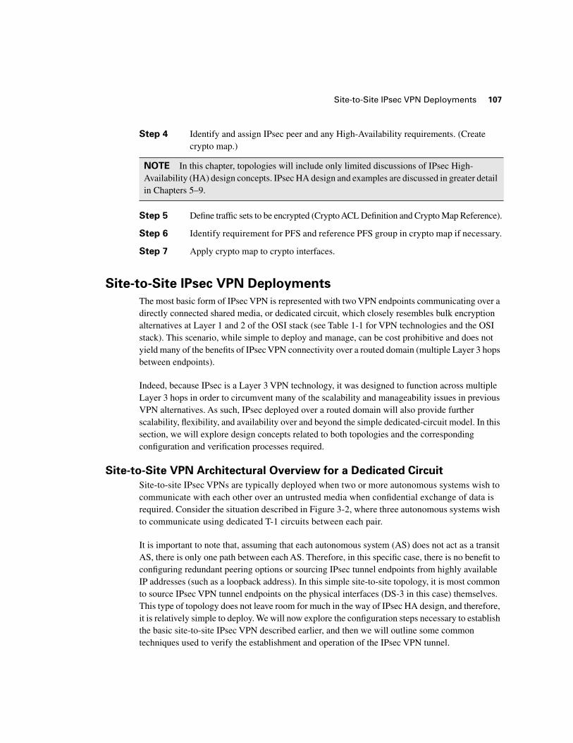
Site-to-site IPsec VPNs are typically deployed when two or more autonomous systems wish to communicate with each other over an untrusted media when confidential exchange of data is required. Consider the situation described in Figure 3-2, where three autonomous systems wish to communicate using dedicated T-1 circuits between each pair.
It is important to note that, assuming that each autonomous system (AS) does not act as a transit AS, there is only one path between each AS. Therefore, in this specific case, there is no benefit to configuring redundant peering options or sourcing IPsec tunnel endpoints from highly available IP addresses (such as a loopback address). In this simple site-to-site topology, it is most common to source IPsec VPN tunnel endpoints on the physical interfaces (DS-3 in this case) themselves. This type of topology does not leave room for much in the way of IPsec HA design, and therefore, it is relatively simple to deploy. We will now explore the configuration steps necessary to establish the basic site-to-site IPsec VPN described earlier, and then we will outline some common techniques used to verify the establishment and operation of the IPsec VPN tunnel.
NOTE In this chapter, topologies will include only limited discussions of IPsec High-Availability (HA) design concepts. IPsec HA design and examples are discussed in greater detail in Chapters 5–9.
108 Chapter 3: Basic IPsec VPN Topologies and Configurations
Figure 3-2 Site-to-Site IPsec VPN Topology Using Dedicated T-1 Circuits for Communications
Cisco IOS Site-to-Site IPsec VPN Configuration
The configurations in the following examples were all built using the process described in Figure 3-1 and pertain to the topology depicted in Figure 3-2. Some design considerations for these particular IPsec VPNs are as follows:
■ Tunnel mode is used to keep the original IP header confidential.
■ The routers are capable of handling 256-bit AES ESP transforms in hardware. Hash-based Message Authentication Codes (HMAC) are implemented in the transform to ensure integrity in the cipher block chain of encrypted packets traversing the IPsec security association (SA).
■ The DH group is 5 in order to accommodate the large key material needed by the AES transform.
■ There is no certification authority (CA), and the administrators want to use hardware acceleration, which rules out the RSA-encrypted nonces method of authentication. So pre-shared keys are used for Internet Security Association and Key Management Protocol (ISAKMP) authentication.
■ Strong authentication is required during ISAKMP, so the hash is SHA-1 and the symmetric transform for the IKE SA is 3DES.
ESP
ESP
ESP
Loopback 1201.1.1.1/32AS1-7304A
AS #2Loopback 1202.1.1.1/32AS2-3745A
AS #3Loopback 1203.1.1.1/32AS3-3745A
AS #1
DS-3200.1.1.0/30
DS-3200.1.1.8/30
DS-3200.1.1.4/30
GRE Encapsulated Tunnels
Site-to-Site IPsec VPN Deployments 109
■ It is desirable to have the IPsec session keys derived independently (as opposed to derived from the ISAKMP DH shared secret keys). As such, perfect forward secrecy (PFS) is enabled. Again, the group is 5 to generate the appropriate key material for the IPsec transform (AES).
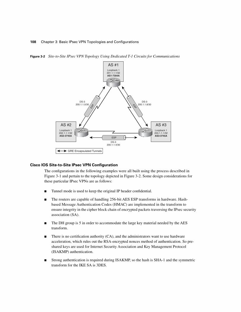
Example 3-1 provides a configuration for the AS1-7301A in Figure 3-2. This router’s configuration employs all of the elements necessary to accommodate a site-to-site IPsec VPN, including the IPsec transform, crypto ACL, and IPsec peer. In this case, AS1-7301A uses two site-to-site IPsec VPNs, to AS#2 and AS#3, respectively. This is accomplished by using two process IDs within the same crypto map (AS1VPN 10 and AS1VPN 20). AS1VPN, process 10, protects traffic from AS1 to AS2, as defined in Crypto ACL 101. AS1VPN, process 20, protects traffic from AS1 to AS3 (Example 3-1, line 14), as defined in Crypto ACL 102 (Example 3-1, line 15).
NOTE The preceding VPN considerations describe a relatively strong cryptographic suite. As such, computation resources on the routers must be somewhat substantial to accommodate them. It is important that one weigh the amount of available computational resources against the organization’s performance and security requirements before building IPsec VPN configurations.
Example 3-1 Site-to-Site VPN Configuration on AS1-7301A
AS1-7304A#sssshhhhoooowwww rrrruuuunnnnnnnniiiinnnngggg----ccccoooonnnnffffiiiigggg
!
crypto ipsec transform-set ivdf3-1 esp-aes esp-sha-hmac
crypto map AS1VPN 10 ipsec-isakmp
set peer 200.1.1.2
set transform-set ivdf3-1
match address 101
set pfs group5
crypto map AS1VPN 20 ipsec-isakmp
set peer 200.1.1.10
set transform-set ivdf3-1
match address 102
set pfs group5
access-list 101 permit ip 211.0.0.0 0.255.255.255 212.0.0.0 0.255.255.255
access-list 102 permit ip 211.0.0.0 0.255.255.255 213.0.0.0 0.255.255.255
!
interface HSSI1/0
ip address 200.1.1.1 255.255.255.252
encapsulation HDLC
crypto map AS1VPN
interface HSSI2/0
ip address 200.1.1.9 255.255.255.252
encapsulation HDLC
crypto map AS1VPN
110 Chapter 3: Basic IPsec VPN Topologies and Configurations
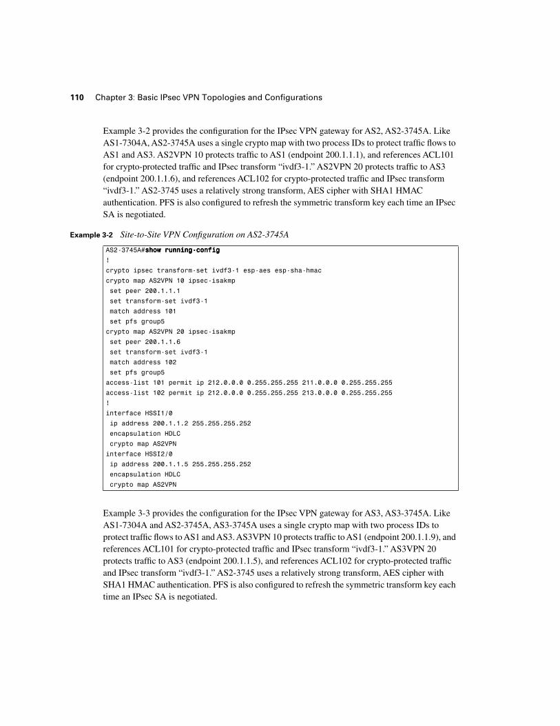
Example 3-2 provides the configuration for the IPsec VPN gateway for AS2, AS2-3745A. Like AS1-7304A, AS2-3745A uses a single crypto map with two process IDs to protect traffic flows to AS1 and AS3. AS2VPN 10 protects traffic to AS1 (endpoint 200.1.1.1), and references ACL101 for crypto-protected traffic and IPsec transform “ivdf3-1.” AS2VPN 20 protects traffic to AS3 (endpoint 200.1.1.6), and references ACL102 for crypto-protected traffic and IPsec transform “ivdf3-1.” AS2-3745 uses a relatively strong transform, AES cipher with SHA1 HMAC authentication. PFS is also configured to refresh the symmetric transform key each time an IPsec SA is negotiated.
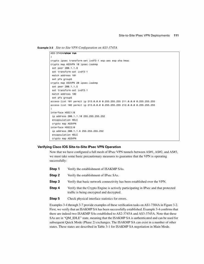
Example 3-3 provides the configuration for the IPsec VPN gateway for AS3, AS3-3745A. Like AS1-7304A and AS2-3745A, AS3-3745A uses a single crypto map with two process IDs to protect traffic flows to AS1 and AS3. AS3VPN 10 protects traffic to AS1 (endpoint 200.1.1.9), and references ACL101 for crypto-protected traffic and IPsec transform “ivdf3-1.” AS3VPN 20 protects traffic to AS3 (endpoint 200.1.1.5), and references ACL102 for crypto-protected traffic and IPsec transform “ivdf3-1.” AS2-3745 uses a relatively strong transform, AES cipher with SHA1 HMAC authentication. PFS is also configured to refresh the symmetric transform key each time an IPsec SA is negotiated.
Example 3-2 Site-to-Site VPN Configuration on AS2-3745A
AS2-3745A#sssshhhhoooowwww rrrruuuunnnnnnnniiiinnnngggg----ccccoooonnnnffffiiiigggg
!
crypto ipsec transform-set ivdf3-1 esp-aes esp-sha-hmac
crypto map AS2VPN 10 ipsec-isakmp
set peer 200.1.1.1
set transform-set ivdf3-1
match address 101
set pfs group5
crypto map AS2VPN 20 ipsec-isakmp
set peer 200.1.1.6
set transform-set ivdf3-1
match address 102
set pfs group5
access-list 101 permit ip 212.0.0.0 0.255.255.255 211.0.0.0 0.255.255.255
access-list 102 permit ip 212.0.0.0 0.255.255.255 213.0.0.0 0.255.255.255
!
interface HSSI1/0
ip address 200.1.1.2 255.255.255.252
encapsulation HDLC
crypto map AS2VPN
interface HSSI2/0
ip address 200.1.1.5 255.255.255.252
encapsulation HDLC
crypto map AS2VPN
Site-to-Site IPsec VPN Deployments 111
Verifying Cisco IOS Site-to-Site IPsec VPN Operation
Now that we have configured a full mesh of IPsec VPN tunnels between AS#1, AS#2, and AS#3, we must take some basic precautionary measures to guarantee that the VPN is operating successfully:
Step 1 Verify the establishment of ISAKMP SAs.
Step 2 Verify the establishment of IPsec SAs.
Step 3 Verify that basic network connectivity has been established over the VPN.
Step 4 Verify that the Crypto Engine is actively participating in IPsec and that protected traffic is being encrypted and decrypted.
Step 5 Check physical interface statistics for errors.
Examples 3-4 through 3-7 provide examples of these verification tasks on AS1-7304A in Figure 3-2. First, we verify that an ISAKMP SA has been successfully established. Example 3-4 confirms that there are indeed two ISAKMP SAs established to AS2-3745A and AS3-3745A. Note that these SAs are in “QM_IDLE” state, meaning that the ISAKMP SA is authenticated and can be used for subsequent Quick Mode (Phase 2) exchanges. The ISAKMP SA can exist in a number of other states. These states are described in Table 3-1 for ISAKMP SA negotiation in Main Mode.
Example 3-3 Site-to-Site VPN Configuration on AS3-3745A
AS3-3745A#sssshhhhoooowwww rrrruuuunnnn
!
crypto ipsec transform-set ivdf3-1 esp-aes esp-sha-hmac
crypto map AS3VPN 10 ipsec-isakmp
set peer 200.1.1.9
set transform-set ivdf3-1
match address 101
set pfs group5
crypto map AS3VPN 20 ipsec-isakmp
set peer 200.1.1.5
set transform-set ivdf3-1
match address 102
set pfs group5
access-list 101 permit ip 213.0.0.0 0.255.255.255 211.0.0.0 0.255.255.255
access-list 102 permit ip 213.0.0.0 0.255.255.255 212.0.0.0 0.255.255.255
!
interface HSSI1/0
ip address 200.1.1.10 255.255.255.252
encapsulation HDLC
crypto map AS3VPN
interface HSSI2/0
ip address 200.1.1.6 255.255.255.252
encapsulation HDLC
crypto map AS3VPN

112 Chapter 3: Basic IPsec VPN Topologies and Configurations
Though the SA described in Example 3-4 was negotiated using Main Mode, Aggressive Mode could have been used instead. Table 3-2 presents the ISAKMP SA states and their descriptions for SAs negotiated with Aggressive Mode. Note that in Table 3-2, there are inherently fewer states described for Aggressive Mode, because Aggressive Mode involves fewer message exchanges than does Main Mode.
Table 3-1 ISAKMP SA States for IKE Main Mode SA Negotiation
IKE SA State (Main Mode) Description
MM_NO_STATE The ISAKMP SA has been created, but nothing else has happened yet. It is “larval” at this stage—there is no state.
MM_SA_SETUP The peers have agreed on parameters for the ISAKMP SA.
MM_KEY_EXCH The peers have exchanged Diffie-Hellman public keys and have generated a shared secret. The ISAKMP SA remains unauthenticated.
MM_KEY_AUTH The ISAKMP SA has been authenticated. If the router initiated this exchange, this state transitions immediately to QM_IDLE, and a Quick Mode exchange begins.
Table 3-2 ISAKMP SA States for IKE Aggressive Mode Negotiation
IKE SA State (Aggressive Mode) Description
AG_NO_STATE The ISAKMP SA has been created, but nothing else has happened yet. It is “larval” at this stage—there is no state.
AG_INIT_EXCH The peers have done the first exchange in Aggressive Mode, but the SA is not authenticated.
AG_AUTH The peers have done the first exchange in Aggressive Mode, but the SA is not authenticated.
Example 3-4 Verification of ISAKMP SAs for AS1-7304A
AS1-7304A#sssshhhhoooowwww ccccrrrryyyyppppttttoooo iiiissssaaaakkkkmmmmpppp ssssaaaa
dst src state conn-id slot
200.1.1.10 200.1.1.9 QM_IDLE 2 0
200.1.1.1 200.1.1.2 QM_IDLE 1 0

Site-to-Site IPsec VPN Deployments 113
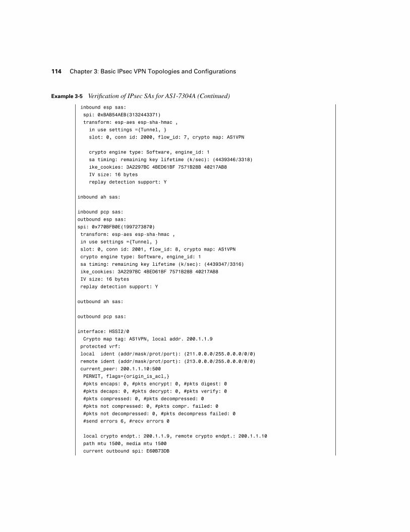
After we can verify that Phase 1 SAs are established (by examining the output listed in Example 3-4), we are then ready to verify the establishment of IPsec SAs. Example 3-5 provides output needed to verify several important elements of Phase 2 SA establishment:
■ The IPsec VPN Peer Address for the SA (200.1.1.2 for AS1VPN process 10 and 200.1.1.10 for AS1VPN process 20).
■ The crypto-protected IPsec address sets specified in the Crypto ACLs for this SA (211.0.0.0/8->212.0.0.0/8 for AS1VPN process 10 and 211.0.0.0/8->213.0.0.0/8 for AS1VPN process 20).
■ Inbound SA information, including IPsec transform used, crypto map used, initialization value (IV), and replay information. Note that there are fields for ESP, PCP, and Authentication Header (AH)—only the ESP fields are populated because there is no AH specified in the transform set for this IPsec SA.
■ Outbound SA information, including IPsec Transform used, crypto map used, IV, and replay information. Note that there are fields for ESP, PCP, and AH—only the ESP fields are populated as there is no AH specified in the transform set for this IPsec SA.
■ The peering encryption/decryption activity for this security association.
NOTE These statistics will change to match the crypto engine statistics listed in Example 3-7 after traffic is sent across the tunnel in Example 3-6.
Example 3-5 Verification of IPsec SAs for AS1-7304A
AS1-7304A#sssshhhhoooowwww ccccrrrryyyyppppttttoooo IIIIPPPPsssseeeecccc ssssaaaa
interface: HSSI1/0
Crypto map tag: AS1VPN, local addr. 200.1.1.1
protected vrf:
local ident (addr/mask/prot/port): (211.0.0.0/255.0.0.0/0/0)
remote ident (addr/mask/prot/port): (212.0.0.0/255.0.0.0/0/0)
current_peer: 200.1.1.2:500
PERMIT, flags={origin_is_acl,}
#pkts encaps: 0, #pkts encrypt: 0, #pkts digest: 0
#pkts decaps: 0, #pkts decrypt: 0, #pkts verify: 0
#pkts compressed: 0, #pkts decompressed: 0
#pkts not compressed: 0, #pkts compr. failed: 0
#pkts not decompressed: 0, #pkts decompress failed: 0
#send errors 1, #recv errors 0
local crypto endpt.: 200.1.1.1, remote crypto endpt.: 200.1.1.2
path mtu 1500, media mtu 1500
current outbound spi: 770BFB0E
continues
114 Chapter 3: Basic IPsec VPN Topologies and Configurations
inbound esp sas:
spi: 0xBAB54AEB(3132443371)
transform: esp-aes esp-sha-hmac ,
in use settings ={Tunnel, }
slot: 0, conn id: 2000, flow_id: 7, crypto map: AS1VPN
crypto engine type: Software, engine_id: 1
sa timing: remaining key lifetime (k/sec): (4439346/3318)
ike_cookies: 3A2297BC 4BED61BF 7571B28B 40217AB8
IV size: 16 bytes
replay detection support: Y
inbound ah sas:
inbound pcp sas:
outbound esp sas:
spi: 0x770BFB0E(1997273870)
transform: esp-aes esp-sha-hmac ,
in use settings ={Tunnel, }
slot: 0, conn id: 2001, flow_id: 8, crypto map: AS1VPN
crypto engine type: Software, engine_id: 1
sa timing: remaining key lifetime (k/sec): (4439347/3316)
ike_cookies: 3A2297BC 4BED61BF 7571B28B 40217AB8
IV size: 16 bytes
replay detection support: Y
outbound ah sas:
outbound pcp sas:
interface: HSSI2/0
Crypto map tag: AS1VPN, local addr. 200.1.1.9
protected vrf:
local ident (addr/mask/prot/port): (211.0.0.0/255.0.0.0/0/0)
remote ident (addr/mask/prot/port): (213.0.0.0/255.0.0.0/0/0)
current_peer: 200.1.1.10:500
PERMIT, flags={origin_is_acl,}
#pkts encaps: 0, #pkts encrypt: 0, #pkts digest: 0
#pkts decaps: 0, #pkts decrypt: 0, #pkts verify: 0
#pkts compressed: 0, #pkts decompressed: 0
#pkts not compressed: 0, #pkts compr. failed: 0
#pkts not decompressed: 0, #pkts decompress failed: 0
#send errors 6, #recv errors 0
local crypto endpt.: 200.1.1.9, remote crypto endpt.: 200.1.1.10
path mtu 1500, media mtu 1500
current outbound spi: E60B73DB
Example 3-5 Verification of IPsec SAs for AS1-7304A (Continued)
Site-to-Site IPsec VPN Deployments 115
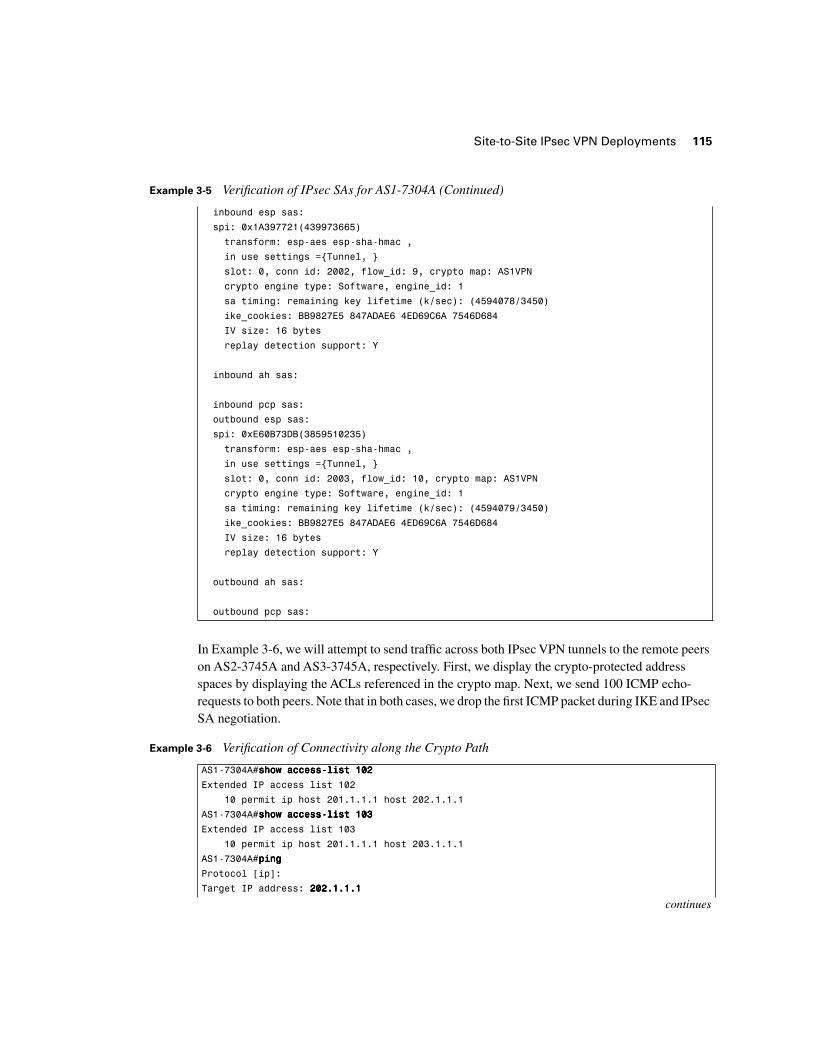
In Example 3-6, we will attempt to send traffic across both IPsec VPN tunnels to the remote peers on AS2-3745A and AS3-3745A, respectively. First, we display the crypto-protected address spaces by displaying the ACLs referenced in the crypto map. Next, we send 100 ICMP echo-requests to both peers. Note that in both cases, we drop the first ICMP packet during IKE and IPsec SA negotiation.
inbound esp sas:
spi: 0x1A397721(439973665)
transform: esp-aes esp-sha-hmac ,
in use settings ={Tunnel, }
slot: 0, conn id: 2002, flow_id: 9, crypto map: AS1VPN
crypto engine type: Software, engine_id: 1
sa timing: remaining key lifetime (k/sec): (4594078/3450)
ike_cookies: BB9827E5 847ADAE6 4ED69C6A 7546D684
IV size: 16 bytes
replay detection support: Y
inbound ah sas:
inbound pcp sas:
outbound esp sas:
spi: 0xE60B73DB(3859510235)
transform: esp-aes esp-sha-hmac ,
in use settings ={Tunnel, }
slot: 0, conn id: 2003, flow_id: 10, crypto map: AS1VPN
crypto engine type: Software, engine_id: 1
sa timing: remaining key lifetime (k/sec): (4594079/3450)
ike_cookies: BB9827E5 847ADAE6 4ED69C6A 7546D684
IV size: 16 bytes
replay detection support: Y
outbound ah sas:
outbound pcp sas:
Example 3-6 Verification of Connectivity along the Crypto Path
AS1-7304A#sssshhhhoooowwww aaaacccccccceeeessssssss----lllliiiisssstttt 111100002222
Extended IP access list 102
10 permit ip host 201.1.1.1 host 202.1.1.1
AS1-7304A#sssshhhhoooowwww aaaacccccccceeeessssssss----lllliiiisssstttt 111100003333
Extended IP access list 103
10 permit ip host 201.1.1.1 host 203.1.1.1
AS1-7304A#ppppiiiinnnngggg
Protocol [ip]:
Target IP address: 222200002222....1111....1111....1111
continues
Example 3-5 Verification of IPsec SAs for AS1-7304A (Continued)

116 Chapter 3: Basic IPsec VPN Topologies and Configurations
After we have successfully sent traffic to the remote crypto endpoints, we must then verify that it was successfully encrypted by the IPsec crypto engine. Example 3-7 provides the active IKE and IPsec SAs resident in the crypto engine for AS1-7304A. Note that the SAs with IDs 1 and 2 have not increased their packet count. This is expected, because these are the ISAKMP SAs (the same
Repeat count [5]: 111100000000
Datagram size [100]:
Timeout in seconds [2]:
Extended commands [n]: yyyy
Source address or interface: 222200001111....1111....1111....1111
Type of service [0]:
Set DF bit in IP header? [no]:
Validate reply data? [no]:
Data pattern [0xABCD]:
Loose, Strict, Record, Timestamp, Verbose[none]:
Sweep range of sizes [n]:
Type escape sequence to abort.
Sending 100, 100-byte ICMP Echos to 202.1.1.1, timeout is 2 seconds:
Packet sent with a source address of 201.1.1.1
.!!!!!!!!!!!!!!!!!!!!!!!!!!!!!!!!!!!!!!!!!!!!!!!!!!!!!!!!!!!!!!!!!!!!!
!!!!!!!!!!!!!!!!!!!!!!!!!!!!!!
Success rate is 99 percent (99/100), round-trip min/avg/max = 44/46/48 ms
AS1-7304A#ppppiiiinnnngggg
Protocol [ip]:
Target IP address: 222200003333....1111....1111....1111
Repeat count [5]: 111100000000
Datagram size [100]:
Timeout in seconds [2]:
Extended commands [n]: yyyy
Source address or interface: 222200001111....1111....1111....1111
Type of service [0]:
Set DF bit in IP header? [no]:
Validate reply data? [no]:
Data pattern [0xABCD]:
Loose, Strict, Record, Timestamp, Verbose[none]:
Sweep range of sizes [n]:
Type escape sequence to abort.
Sending 100, 100-byte ICMP Echos to 203.1.1.1, timeout is 2 seconds:
Packet sent with a source address of 201.1.1.1
.!!!!!!!!!!!!!!!!!!!!!!!!!!!!!!!!!!!!!!!!!!!!!!!!!!!!!!!!!!!!!!!!!!!!!
!!!!!!!!!!!!!!!!!!!!!!!!!!!!!!
Success rate is 99 percent (99/100), round-trip min/avg/max = 44/46/52 ms
Example 3-6 Verification of Connectivity along the Crypto Path (Continued)
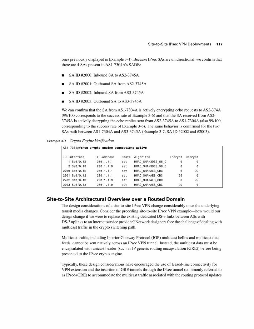
Site-to-Site IPsec VPN Deployments 117
ones previously displayed in Example 3-4). Because IPsec SAs are unidirectional, we confirm that there are 4 SAs present in AS1-7304A’s SADB:
■ SA ID #2000: Inbound SA to AS2-3745A
■ SA ID #2001: Outbound SA from AS2-3745A
■ SA ID #2002: Inbound SA from AS3-3745A
■ SA ID #2003: Outbound SA to AS3-3745A
We can confirm that the SA from AS1-7304A is actively encrypting echo requests to AS2-374A (99/100 corresponds to the success rate of Example 3-6) and that the SA received from AS2-3745A is actively decrypting the echo replies sent from AS2-3745A to AS1-7304A (also 99/100, corresponding to the success rate of Example 3-6). The same behavior is confirmed for the two SAs built between AS1-7304A and AS3-3745A (Example 3-7, SA ID #2002 and #2003).
Site-to-Site Architectural Overview over a Routed Domain
The design considerations of a site-to-site IPsec VPN change considerably once the underlying transit media changes. Consider the preceding site-to-site IPsec VPN example—how would our design change if we were to replace the existing dedicated DS-3 links between ASs with DS-3 uplinks to an Internet service provider? Network designers face the challenge of dealing with multicast traffic in the crypto switching path.
Multicast traffic, including Interior Gateway Protocol (IGP) multicast hellos and multicast data feeds, cannot be sent natively across an IPsec VPN tunnel. Instead, the multicast data must be encapsulated with unicast header (such as IP generic routing encapsulation (GRE)) before being presented to the IPsec crypto engine.
Typically, these design considerations have encouraged the use of leased-line connectivity for VPN extension and the insertion of GRE tunnels through the IPsec tunnel (commonly referred to as IPsec+GRE) to accommodate the multicast traffic associated with the routing protocol updates
Example 3-7 Crypto Engine Verification
AS1-7304A#sssshhhhoooowwww ccccrrrryyyyppppttttoooo eeeennnnggggiiiinnnneeee ccccoooonnnnnnnneeeeccccttttiiiioooonnnnssss aaaaccccttttiiiivvvveeee
ID Interface IP-Address State Algorithm Encrypt Decrypt
1 Se0/0.12 200.1.1.1 set HMAC_SHA+3DES_56_C 0 0
2 Se0/0.13 200.1.1.9 set HMAC_SHA+3DES_56_C 0 0
2000 Se0/0.12 200.1.1.1 set HMAC_SHA+AES_CBC 0 99
2001 Se0/0.12 200.1.1.1 set HMAC_SHA+AES_CBC 99 0
2002 Se0/0.13 200.1.1.9 set HMAC_SHA+AES_CBC 0 99
2003 Se0/0.13 200.1.1.9 set HMAC_SHA+AES_CBC 99 0
118 Chapter 3: Basic IPsec VPN Topologies and Configurations
and hellos. The need for enterprise connectivity extension across intermediate routed domains is growing rapidly. Two common enterprise IPsec deployments that are driving this growth are corporate extranet deployments and RAVPN deployments.
Consider the following example, in which a large automotive manufacturer wants to securely extend connectivity from its corporate headquarters network to a series of smaller home offices over an independently maintained routed domain, such as the Internet. The smaller branch offices consist of a number of routed nodes and, as such, would benefit from getting Route Processor (RP) updates from the campus network. Figure 3-3 demonstrates how the addition of a site-to-site IPsec VPN across the independently maintained routed domain would preclude the smaller home offices from exchanging RP updates with the campus network at the corporate HQ.
Due to IPsec’s inability to natively encrypt multicast traffic, the design in Figure 3-3 presents the following design considerations:
■ When the branches recover from Integrated Services Digital Network (ISDN) failover, routing protocol updates to from Branch1 and Branch2 will not be encrypted. In this scenario, IGP updates are multicast-based and will not be included in the crypto switching path.
■ Any changes that occur in Branch1 Net and Branch2 Net will trigger RP update information to the corporate HQ. These updates will be sent in the clear.
■ Any changes within the “HQ Campus Net” will trigger RP updates to the branches that will be sent in the clear.
The solution to these design considerations is to add GRE tunnels to the IPsec VPN implemen-tation. RP traffic between the corporate HQ and branch networks will then be encapsulated with GRE headers and forwarded in the crypto switching path across the ISP network. We will discuss IPsec+GRE architectures in greater detail later in this chapter.
Consider the following example, in which a corporation, a large global financial organization, wants to allow extranet connectivity to its partners. The primary use of this extranet connection is to stream multicast data containing video and market information to decision makers within the global financial organization. This must be done securely and with confidentiality. The insertion of an independently maintained routed domain between the corporate extranet partner and the global financial organization breaks the multicast tree between the two parties, as illustrated in Figure 3-4.

Site-to-Site IPsec VPN Deployments 119
Figure 3-3 IPsec RAVPN Extension to Small Home Office over the Internet
B1-3745ALoopback 1202.1.1.1/32
B2-3745ALoopback 1203.1.1.1/32
T-1 Recovery from ISDN FailoverIPSec VPNsRouting Protocol Update
DS-3200.1.1.0/30 ISDN-PRI
199.1.1.0/24
ISDN-BRI199.1.1.4/30
ISDN-BRI199.1.1.8/30
Si
Corporate HQ
201.3.1.0/30
Si
HQ Campus Net201.4.0.0/16
Branch1 Net201.4.129.0/28
Branch2 Net201.4.129.128/28
Branch-1 Branch-2
T-1200.1.1.4/30
T-1200.1.1.8/30
1
1
2 2
201.3.1.4/30
ISP
Loopback 1201.2.2.2/32HQ-3745AS
Loopback 1201.1.1.1/32HQ-7304A
3
120 Chapter 3: Basic IPsec VPN Topologies and Configurations
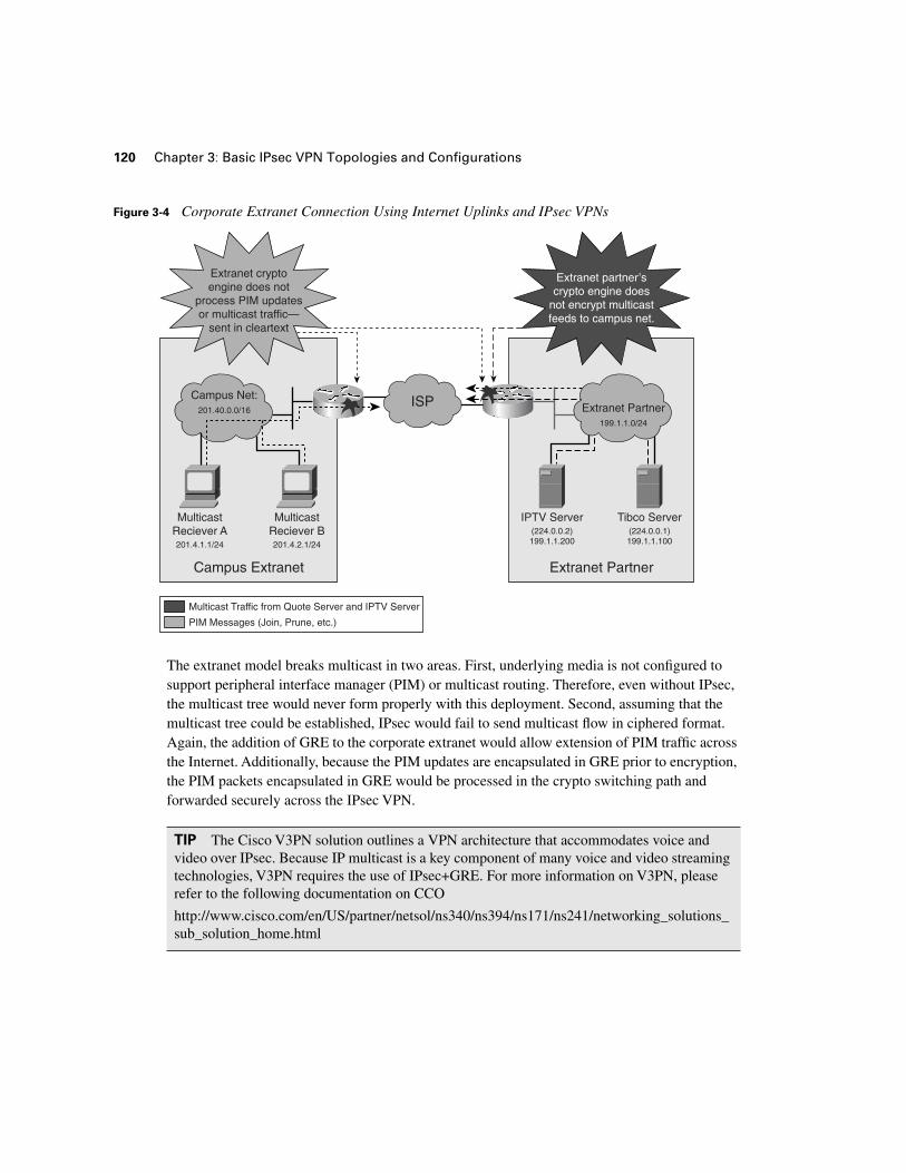
Figure 3-4 Corporate Extranet Connection Using Internet Uplinks and IPsec VPNs
The extranet model breaks multicast in two areas. First, underlying media is not configured to support peripheral interface manager (PIM) or multicast routing. Therefore, even without IPsec, the multicast tree would never form properly with this deployment. Second, assuming that the multicast tree could be established, IPsec would fail to send multicast flow in ciphered format. Again, the addition of GRE to the corporate extranet would allow extension of PIM traffic across the Internet. Additionally, because the PIM updates are encapsulated in GRE prior to encryption, the PIM packets encapsulated in GRE would be processed in the crypto switching path and forwarded securely across the IPsec VPN.
TIP The Cisco V3PN solution outlines a VPN architecture that accommodates voice and video over IPsec. Because IP multicast is a key component of many voice and video streaming technologies, V3PN requires the use of IPsec+GRE. For more information on V3PN, please refer to the following documentation on CCO
http://www.cisco.com/en/US/partner/netsol/ns340/ns394/ns171/ns241/networking_solutions_ sub_solution_home.html
MulticastReciever A201.4.1.1/24
Campus Net:201.40.0.0/16
MulticastReciever B201.4.2.1/24
IPTV Server(224.0.0.2)199.1.1.200
Tibco Server(224.0.0.1)199.1.1.100
ISP Extranet Partner199.1.1.0/24
Extranet cryptoengine does not
process PIM updatesor multicast traffic—
sent in cleartext
Extranet partner’scrypto engine does
not encrypt multicastfeeds to campus net.
Multicast Traffic from Quote Server and IPTV Server
PIM Messages (Join, Prune, etc.)
Campus Extranet Extranet Partner
Site-to-Site IPsec VPN Deployments and GRE (IPsec+GRE) 121
Site-to-Site IPsec VPN Deployments and GRE (IPsec+GRE)
At the core of IPsec is point-to-point functionality, which is not suited for all of today’s IP communications. Indeed, many of today’s voice and video applications require point-to-multipoint connectivity. As such, they leverage IP multicast techniques to selectively flood data to interested parties. Traditionally, IP multicast traffic has not effectively been passed through the crypto switching path on IPsec routers. As we have discussed, this precludes users from encrypting multicast applications such as multicast voice (hoot-n-holler), multicast video (IPTV), and routing protocols (OSPF, ISIS, RIP, EIGRP). The current solution for accommodating these types of traffic in cipher-text is IPsec+GRE.
Site-to-Site IPsec+GRE Architectural Overview
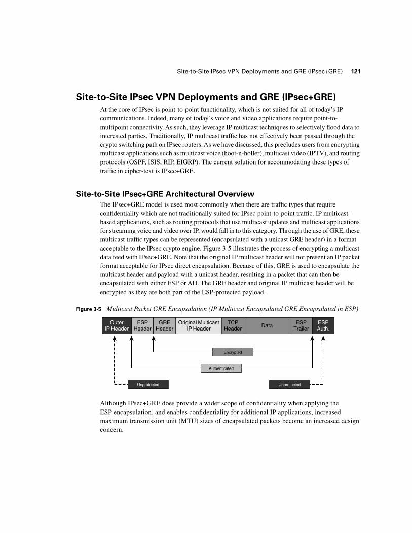
The IPsec+GRE model is used most commonly when there are traffic types that require confidentiality which are not traditionally suited for IPsec point-to-point traffic. IP multicast-based applications, such as routing protocols that use multicast updates and multicast applications for streaming voice and video over IP, would fall in to this category. Through the use of GRE, these multicast traffic types can be represented (encapsulated with a unicast GRE header) in a format acceptable to the IPsec crypto engine. Figure 3-5 illustrates the process of encrypting a multicast data feed with IPsec+GRE. Note that the original IP multicast header will not present an IP packet format acceptable for IPsec direct encapsulation. Because of this, GRE is used to encapsulate the multicast header and payload with a unicast header, resulting in a packet that can then be encapsulated with either ESP or AH. The GRE header and original IP multicast header will be encrypted as they are both part of the ESP-protected payload.
Figure 3-5 Multicast Packet GRE Encapsulation (IP Multicast Encapsulated GRE Encapsulated in ESP)
Although IPsec+GRE does provide a wider scope of confidentiality when applying the ESP encapsulation, and enables confidentiality for additional IP applications, increased maximum transmission unit (MTU) sizes of encapsulated packets become an increased design concern.
OuterIP Header
ESPHeader
ESPTrailer
ESPAuth.
TCPHeader
GREHeader
Original MulticastIP Header Data
Encrypted
Unprotected Unprotected
Authenticated
122 Chapter 3: Basic IPsec VPN Topologies and Configurations
Increased Packet Size and Path MTU Considerations
Packets continue to get larger and larger as continuous layers of encapsulation are added to the original IP payload. For example, an IP-encapsulated RTP packet for voice of 64 bytes in length grows to approximately 128 bytes after it is encapsulated in RTP (12 bytes), UDP (8 bytes), IP (20 bytes), and GRE (24 bytes), and to 184 bytes after the GRE-encapsulated RTP packet is encapsulated again with an ESP header, padding and authentication fields, and trailer (subtotal of approximately 56 bytes). Increasing packet sizes in this fashion also increases the chances that the packet will be fragmented after it has been encrypted, as would be the case if the encrypted packet exceeds the MTU of a link somewhere in the path between the two VPN endpoints. This can cause problems on the decrypting router, which will attempt to decrypt the fragmented packets in the process switching path (without hardware assist), causing scalability issues in terms of performance. Path MTU discovery can be deployed in conjunction with the Cisco IOS IPsec prefragmentation, enabling the encrypting router to dynamically determine the smallest MTU of the path between VPN endpoints. The encrypting VPN router is then capable of fragmenting to the appropriate MTU for the path on a per-SA basis using IPsec prefragmentation, assuring that the fragmentation of IPsec packets always occurs prior to encryption and is therefore done in the fast path.
GRE and Weighted Fair Queuing
Some quality of service (QoS) techniques, such as weighted fair queuing (WFQ), perform conversation hashing decisions based on the original source and destination IP address, which can be ubiquified after IPsec or GRE encapsulation. While DiffServ markings are copied to the outer IP header in tunnel mode IPsec, the original source and destination are not carried forward into outer IP header. In order to appropriately execute hashing decisions in WFQ operations, packets must therefore be classified prior to encapsulation. Cisco IOS supports IPsec QoS pre-classify functionality on IOS VPN endpoints to assure that flow and conversation-based queuing decisions can be executed accurately in IPsec VPN environments.
QoS and the IPsec Anti-Replay Window
Altering the scheduling of packets before IPsec processing (as is the case with QoS pre-classify) conflicts with sequencing schemes native to IPsec that are used for anti-replay protection. Cisco IOS offers IPsec QoS Pre-Classify, which allows packets to be queued prior to ESP, AH, or GRE encapsulation. Alternatively, anti-replay windows can be increased to ensure that IPsec packets are received within the anti-replay window even when reordered and delayed due to queuing decisions on nodes between IPsec VPN endpoints. When deploying QoS in vendor-diverse environments, it is recommended that the operation be monitored to ensure that packet reordering does not conflict with anti-replay functions native to IPsec.
NOTE Common fragmentation issues in IPsec VPNs are discussed in detail in Chapter 4, “Common IPsec VPN Issues.” Available solutions for fragmenting prior to encryption, including path MTU discovery and IPsec prefragmentation, are also discussed in Chapter 4.
Site-to-Site IPsec VPN Deployments and GRE (IPsec+GRE) 123
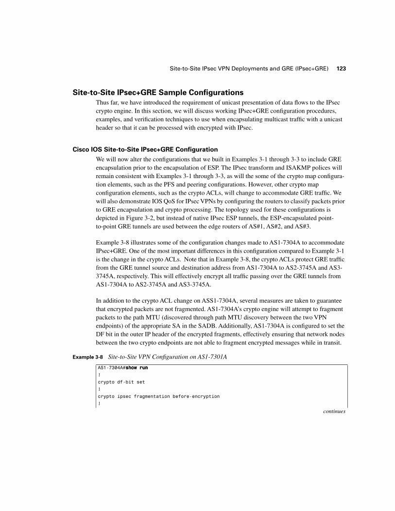
Site-to-Site IPsec+GRE Sample Configurations
Thus far, we have introduced the requirement of unicast presentation of data flows to the IPsec crypto engine. In this section, we will discuss working IPsec+GRE configuration procedures, examples, and verification techniques to use when encapsulating multicast traffic with a unicast header so that it can be processed with encrypted with IPsec.
Cisco IOS Site-to-Site IPsec+GRE Configuration
We will now alter the configurations that we built in Examples 3-1 through 3-3 to include GRE encapsulation prior to the encapsulation of ESP. The IPsec transform and ISAKMP polices will remain consistent with Examples 3-1 through 3-3, as will the some of the crypto map configura-tion elements, such as the PFS and peering configurations. However, other crypto map configuration elements, such as the crypto ACLs, will change to accommodate GRE traffic. We will also demonstrate IOS QoS for IPsec VPNs by configuring the routers to classify packets prior to GRE encapsulation and crypto processing. The topology used for these configurations is depicted in Figure 3-2, but instead of native IPsec ESP tunnels, the ESP-encapsulated point-to-point GRE tunnels are used between the edge routers of AS#1, AS#2, and AS#3.
Example 3-8 illustrates some of the configuration changes made to AS1-7304A to accommodate IPsec+GRE. One of the most important differences in this configuration compared to Example 3-1 is the change in the crypto ACLs. Note that in Example 3-8, the crypto ACLs protect GRE traffic from the GRE tunnel source and destination address from AS1-7304A to AS2-3745A and AS3-3745A, respectively. This will effectively encrypt all traffic passing over the GRE tunnels from AS1-7304A to AS2-3745A and AS3-3745A.
In addition to the crypto ACL change on ASS1-7304A, several measures are taken to guarantee that encrypted packets are not fragmented. AS1-7304A’s crypto engine will attempt to fragment packets to the path MTU (discovered through path MTU discovery between the two VPN endpoints) of the appropriate SA in the SADB. Additionally, AS1-7304A is configured to set the DF bit in the outer IP header of the encrypted fragments, effectively ensuring that network nodes between the two crypto endpoints are not able to fragment encrypted messages while in transit.
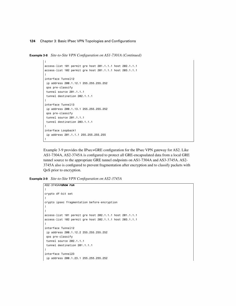
Example 3-8 Site-to-Site VPN Configuration on AS1-7301A
AS1-7304A#sssshhhhoooowwww rrrruuuunnnn
!
crypto df-bit set
!
crypto ipsec fragmentation before-encryption
!
continues
124 Chapter 3: Basic IPsec VPN Topologies and Configurations
Example 3-9 provides the IPsec+GRE configuration for the IPsec VPN gateway for AS2. Like AS1-7304A, AS2-3745A is configured to protect all GRE-encapsulated data from a local GRE tunnel source to the appropriate GRE tunnel endpoints on AS1-7304A and AS3-3745A. AS2-3745A also is configured to prevent fragmentation after encryption and to classify packets with QoS prior to encryption.
!
access-list 101 permit gre host 201.1.1.1 host 202.1.1.1
access-list 102 permit gre host 201.1.1.1 host 203.1.1.1
!
interface Tunnel12
ip address 200.1.12.1 255.255.255.252
qos pre-classify
tunnel source 201.1.1.1
tunnel destination 202.1.1.1
!
interface Tunnel13
ip address 200.1.13.1 255.255.255.252
qos pre-classify
tunnel source 201.1.1.1
tunnel destination 203.1.1.1
!
interface Loopback1
ip address 201.1.1.1 255.255.255.255
!
Example 3-9 Site-to-Site VPN Configuration on AS2-3745A
AS2-3745A#sssshhhhoooowwww rrrruuuunnnn
!
crypto df-bit set
!
crypto ipsec fragmentation before-encryption
!
!
access-list 101 permit gre host 202.1.1.1 host 201.1.1.1
access-list 102 permit gre host 202.1.1.1 host 203.1.1.1
!
interface Tunnel12
ip address 200.1.12.2 255.255.255.252
qos pre-classify
tunnel source 202.1.1.1
tunnel destination 201.1.1.1
!
interface Tunnel23
ip address 200.1.23.1 255.255.255.252
Example 3-8 Site-to-Site VPN Configuration on AS1-7301A (Continued)
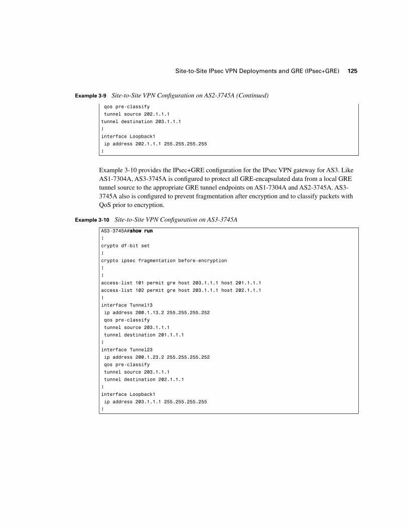
Site-to-Site IPsec VPN Deployments and GRE (IPsec+GRE) 125
Example 3-10 provides the IPsec+GRE configuration for the IPsec VPN gateway for AS3. Like AS1-7304A, AS3-3745A is configured to protect all GRE-encapsulated data from a local GRE tunnel source to the appropriate GRE tunnel endpoints on AS1-7304A and AS2-3745A. AS3-3745A also is configured to prevent fragmentation after encryption and to classify packets with QoS prior to encryption.
qos pre-classify
tunnel source 202.1.1.1
tunnel destination 203.1.1.1
!
interface Loopback1
ip address 202.1.1.1 255.255.255.255
!
Example 3-10 Site-to-Site VPN Configuration on AS3-3745A
AS3-3745A#sssshhhhoooowwww rrrruuuunnnn
!
crypto df-bit set
!
crypto ipsec fragmentation before-encryption
!
!
access-list 101 permit gre host 203.1.1.1 host 201.1.1.1
access-list 102 permit gre host 203.1.1.1 host 202.1.1.1
!
interface Tunnel13
ip address 200.1.13.2 255.255.255.252
qos pre-classify
tunnel source 203.1.1.1
tunnel destination 201.1.1.1
!
interface Tunnel23
ip address 200.1.23.2 255.255.255.252
qos pre-classify
tunnel source 203.1.1.1
tunnel destination 202.1.1.1
!
interface Loopback1
ip address 203.1.1.1 255.255.255.255
!
Example 3-9 Site-to-Site VPN Configuration on AS2-3745A (Continued)

126 Chapter 3: Basic IPsec VPN Topologies and Configurations
Verification of IPsec+GRE Tunnel Establishment
Verifying an IPsec+GRE tunnel begins with the same steps that are taken in the verification of a standard IPsec tunnel. Verification of ISAKMP and IPsec SAs must be done, and basic connectivity through the GRE tunnel must be established. However, when GRE is added to the VPN, steps must be taken to verify tunneled connectivity prior to the addition of IPsec:
■ Verification of tunnel establishment
■ Verification of RP (including PIM) adjacencies through the tunnel
Once these basic tunneling operations have been verified, they must be re-verified after the addition of IPsec. In addition to that re-verification, the administrator should also verify the establishment of ISAKMP SA, IPsec SA, and that traffic passed over the IPsec+GRE tunnel is actually being encrypted, as we explored in Examples 3-4 through 3-7. Example 3-8 demonstrates the non-crypto GRE verification steps on AS1-7304A (prior to the addition of the crypto map to the physical interface) and the verification of the full IPsec+GRE tunnel (after the crypto map has been applied to the physical interface). Again, note that all EIGRP traffic is kept confidential from the OSPF core via IPsec processing of all GRE traffic (which in this case includes all EIGRP traffic— 192.168.x.x/16 address space) between endpoints. Example 3-11 illustrates several typical diagnostic steps needed to verify the establishment of a GRE tunnel and of RP adjacencies using that GRE tunnel, including:
■ Verify GRE tunnel establishment and interface status.
■ Verify basic connectivity through the GRE tunnel.
■ Verify RP adjacencies across the GRE tunnel.
Example 3-11 Verification of GRE Tunnels and Tunneled Routing Protocols on AS1-7304A
AS1-7304A#sssshhhhoooowwww iiiipppp iiiinnnntttt bbbbrrrriiiieeeeffff
Interface IP-Address OK? Method Status Protocol
FastEthernet0/0 unassigned YES NVRAM administratively down down
Serial0/0 unassigned YES NVRAM up up
Serial0/0.12 200.1.1.1 YES manual up up
Serial0/0.13 200.1.1.9 YES manual up up
Loopback0 201.1.1.1 YES manual up up
Loopback1 192.168.1.1 YES manual up up
Tunnel12 192.168.12.1 YES manual up up
Tunnel13 192.168.13.1 YES manual up up
AS1-7304A#ppppiiiinnnngggg 111199992222....111166668888....11112222....2222
Type escape sequence to abort.
Sending 5, 100-byte ICMP Echos to 192.168.12.2, timeout is 2 seconds:
!!!!!
Success rate is 100 percent (5/5), round-trip min/avg/max = 32/34/36 ms

Site-to-Site IPsec VPN Deployments and GRE (IPsec+GRE) 127
After we have verified the basic operation of the routing protocol adjacencies and updates over the GRE tunnels, we are ready to verify that the crypto engine is processing the GRE tunnel through which subsequent control and data plane traffic will traverse. The diagnostic output in Exam-ple 3-12 verifies that protected traffic (in this case all GRE traffic) is being processed by the crypto engine. This output reflects statistics after 100 pings are forwarded across each GRE (and subsequently IPsec) tunnel. Note that there are more than 100 packets processed by the crypto engine—these extra packets are GRE-tunneled packets using various control plan traffic including RP updates and adjacency maintenance.
AS1-7304A#ppppiiiinnnngggg 111199992222....111166668888....11113333....2222
Type escape sequence to abort.
Sending 5, 100-byte ICMP Echos to 192.168.13.2, timeout is 2 seconds:
!!!!!
Success rate is 100 percent (5/5), round-trip min/avg/max = 32/34/36 ms
AS1-7304A#sssshhhhoooowwww iiiipppp eeeeiiiiggggrrrrpppp iiiinnnntttteeeerrrrffffaaaacccceeeessss
IP-EIGRP interfaces for process 192
Xmit Queue Mean Pacing Time Multicast Pending
Interface Peers Un/Reliable SRTT Un/Reliable Flow Timer Routes
Lo1 0 0/0 0 0/10 0 0
Tu12 1 0/0 736 71/2702 6362 0
Tu13 1 0/0 277 71/2702 3710 0
AS1-7304A#sssshhhh iiiipppp eeeeiiiiggggrrrrpppp nnnneeeeiiiigggghhhhbbbboooorrrrssss
IP-EIGRP neighbors for process 192
H Address Interface Hold Uptime SRTT RTO Q Seq
(sec) (ms) Cnt Num
1 192.168.13.2 Tu13 12 00:18:36 277 5000 0 41
0 192.168.12.2 Tu12 12 00:19:01 736 5000 0 48
Example 3-12 Verification of Crypto-Processed Traffic after Crypto Maps Have Been Applied to Physical Interfaces That Will Protect All GRE Traffic Between the Two GRE Tunnel Endpoints
AS1-7304A#sssshhhh ccccrrrryyyyppppttttoooo eeeennnnggggiiiinnnneeee ccccoooonnnnnnnn aaaaccccttttiiiivvvveeee
ID Interface IP-Address State Algorithm Encrypt Decrypt
1 Se0/0.12 200.1.1.1 set HMAC_SHA+3DES_56_C 0 0
2 Se0/0.13 200.1.1.9 set HMAC_SHA+3DES_56_C 0 0
2002 Se0/0.13 200.1.1.9 set HMAC_SHA+AES_CBC 0 145
2003 Se0/0.13 200.1.1.9 set HMAC_SHA+AES_CBC 146 0
2004 Se0/0.12 200.1.1.1 set HMAC_SHA+AES_CBC 0 139
2005 Se0/0.12 200.1.1.1 set HMAC_SHA+AES_CBC 139 0
Example 3-11 Verification of GRE Tunnels and Tunneled Routing Protocols on AS1-7304A (Continued)
128 Chapter 3: Basic IPsec VPN Topologies and Configurations
Hub-and-Spoke IPsec VPN Deployments
Most of today’s enterprise class IPsec VPN deployments incorporate hub-and-spoke IPsec designs. These designs extend from the principles that we have discussed previously in this chapter, whether the situation describes the aggregation of native spoke IPsec VPNs at a hub IPsec aggregation point or the aggregation of IPsec+GRE VPNs at a hub IPsec and GRE concentrator. As the number of spoke connections increases, so do the number of design considerations surrounding the hub IPsec router. These include the following:
■ SA Scalability—The number of security associations actively supported and dangling SA detection, elimination, and management capabilities. This is less of a concern on spokes as they will only maintain SAs relevant to hub connectivity. Hub SA maintenance becomes an issue, as it must maintain an SADB comprehensive of all spoke VPN connectivity.
■ IPsec Tunnel Capacity—In addition to the number of SAs that the endpoint’s memory can accommodate, one must pay careful attention to the security policy of the tunnel itself and the impact on the CPU that this policy has. Selection of the strongest cryptographic suites comes with a cost of increased computational burden. IPsec VPN design at a hub router that concentrates IPsec VPNs with strong security policies must be sized to accommodate the computational overhead required for tunnel maintenance of the appropriate anticipated scale.
■ Crypto Path Switching Capacity—The throughput, in packets per second (pps), of the traffic that is processed in the router’s crypto (IPsec) switching path must also be considered. Or, if GRE is used, we must look at the throughput in (pps) of the GRE+IPsec switching path.
■ GRE Tunnel Maintenance Capacity—Although most routers will support GRE encapsulation, they do not necessarily do it in the fast switching path (in hardware). When selecting a hub router that will be concentrating GRE tunnels, care must be taken to ensure that extensive GRE encapsulation and decapsulation does not limit throughput or overburden the hub’s CPU.
■ Fragmentation Capabilities—Because each spoke router in the network discovers the MTU en route to its destination, the amount of fragmented packets can potentially increase at IPsec aggregation points. Hub IPsec aggregation/concentration devices must be specified appropriately so as to handle potentially large amounts of fragmented packets sent from adjacent spoke IPsec peer endpoints.
TIP It is recommended that the administrator re-verify the steps taken in Example 3-11 to confirm the operation of GRE and RPs after the crypto map has been added. It is further recommended that the administrator verify the cryptographic elements added to the GRE tunnel using the techniques outlined in our discussion of site-to-site VPNs in Examples 3-4 through 3-7.
Hub-and-Spoke IPsec VPN Deployments 129
Additionally, the urgency for HA at the hub router increases dramatically as additional spokes are reliant on the hub for connectivity to the enterprise’s centrally located resources.
Hub-and-Spoke Architectural Overview
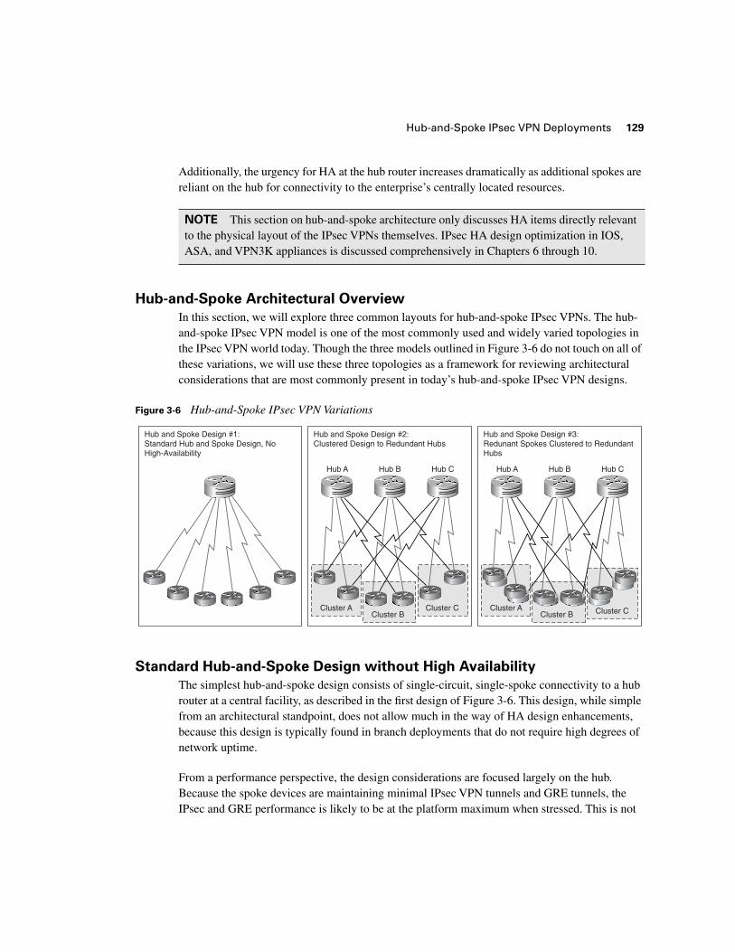
In this section, we will explore three common layouts for hub-and-spoke IPsec VPNs. The hub-and-spoke IPsec VPN model is one of the most commonly used and widely varied topologies in the IPsec VPN world today. Though the three models outlined in Figure 3-6 do not touch on all of these variations, we will use these three topologies as a framework for reviewing architectural considerations that are most commonly present in today’s hub-and-spoke IPsec VPN designs.
Figure 3-6 Hub-and-Spoke IPsec VPN Variations
Standard Hub-and-Spoke Design without High Availability
The simplest hub-and-spoke design consists of single-circuit, single-spoke connectivity to a hub router at a central facility, as described in the first design of Figure 3-6. This design, while simple from an architectural standpoint, does not allow much in the way of HA design enhancements, because this design is typically found in branch deployments that do not require high degrees of network uptime.
From a performance perspective, the design considerations are focused largely on the hub. Because the spoke devices are maintaining minimal IPsec VPN tunnels and GRE tunnels, the IPsec and GRE performance is likely to be at the platform maximum when stressed. This is not
NOTE This section on hub-and-spoke architecture only discusses HA items directly relevant to the physical layout of the IPsec VPNs themselves. IPsec HA design optimization in IOS, ASA, and VPN3K appliances is discussed comprehensively in Chapters 6 through 10.
Cluster CCluster B
Hub A Hub B Hub C
Cluster A Cluster CCluster B
Hub A Hub B Hub C
Cluster A
Hub and Spoke Design #3:Redunant Spokes Clustered to RedundantHubs
Hub and Spoke Design #2:Clustered Design to Redundant Hubs
Hub and Spoke Design #1:Standard Hub and Spoke Design, NoHigh-Availability
130 Chapter 3: Basic IPsec VPN Topologies and Configurations
the case for the hub router, which is responsible for SA and GRE maintenance to all of the spoke routers. This poses several design issues that must be addressed at the hub:
■ SADB Scalability—The hub router must have the appropriate amount of memory to accommodate the SADB for the whole hub/spoke deployment. Remember from our previous discussions in Chapter 2, “IPsec Fundamentals,” that the number of IPsec SAs needed will be the twice the number of IPsec connections plus one SA for each IKE channel.
■ Switching Capacity for IPsec Aggregation—The hub router must have the appropriate amount of switching capacity (in pps) to support the performance requirements in the IPsec+GRE switching path.
■ Excessive Encrypt/Decrypt Action for Spoke-Spoke Traffic—For spoke-spoke connectivity, the hub router will be decrypting traffic from the sending spoke and re-encrypting it before sending it to the destination spoke. For networks that have a substantial amount of spoke-spoke traffic, the hub router that has enough processing power to support substantial amounts of decrypt/re-encrypt behavior must be selected.
■ Multicast Fanout—In this design, the hub router is performing the multicast fanout for traffic to all of the spoke routers that are subscribed to the multicast group. For traffic profiles that have substantial amounts of multicast traffic, the hub router must be capable of accommodating the appropriate amount of packet duplication, the encapsulation of those fanned-out packets in GRE, and the increased amount of IPsec processing that is required as those fanned-out packets are processed by the crypto engine.
Clustered Spoke Design to Redundant Hubs
The second design in Figure 3-6 describes the addition of two hub IPsec aggregation points into the design. This allows network designers to deploy redundancy in the spoke uplinks to the hub routers. It also allows network designers to address the design concerns raised in the first design of Figure 3-6. Deploying redundancy at the hub location of the IPsec hub-and-spoke network presents some key design advantages, including, but not limited to, the following:
■ Increased Tunnel Termination/Maintenance Capacity—Using multiple hub routers decreases the amount of memory required for SA maintenance on a per-platform basis, because the SAs are spread across three aggregation points (as opposed being concentrated
TIP Cisco IOS offers Dynamic Multipoint VPN (DMVPN) features that support the dynamic, direct establishment of spoke-to-spoke SAs in hub-and-spoke deployments. When deployed effectively, this solution can dramatically improve the performance of hub-and-spoke IPsec VPN deployments because IPsec processing is partially transitioned from the hub router to the spokes themselves. DMVPN is discussed in greater detail in Chapter 8, “Handling Vendor Interoperability with High Availability.”
Hub-and-Spoke IPsec VPN Deployments 131
on only one). The distribution of hub processing capabilities also eases the computational burden in terms of IPsec VPN termination, GRE tunnel termination, and the decryption/re-encryption overhead of spoke-to-spoke communication discussed previously.
■ Increased Multicast Fanout Capacity—Distributed Hub IPsec processing also presents two additional multicast fanout points to the design. This type of distribution at the multicast fanout points can dramatically improve the switching performance of the hub-and-spoke deployment, because computational resources for copying multicast packets, encapsulating them in GRE, and encrypting them are tripled at the aggregation points.
■ Load Balancing and Redundancy—In addition to the redundancy provided to the spokes by the two redundant uplinks to their corresponding aggregation points, the correct deployment of redundant circuits allows for a primitive form of load balancing across the three aggregation points—Hubs A, B, and C. Each spoke terminates its primary uplinks on different hubs so that in a nonfailover scenario IPsec VPNs are distributed evenly across the three aggregation points. Each spoke’s backup links are distributed in the same fashion, so as to provide the same load-balancing effect when there is a failover scenario at the spoke.
Redundant Clustered Spoke Design to Redundant Hubs
Design #3 in Figure 3-6 describes a topology similar to Design #2, but with redundant routers at the spoke. This is the most highly–available design discussed in this chapter, and it will lead us in to design concepts discussed in Chapters 6–10. It is also the most expensive of the three designs to deploy, as it doubles the amount of hardware to be purchased at the spoke level.
With respect to the design of the IPsec VPNs themselves, the addition of redundant spoke routers could boost performance of the IPsec VPN, especially if both IPsec tunnels were concurrently active and traffic from the spoke is load-balanced across the two redundant spoke routers. These benefits, however, although useful, are only local to the spoke itself, which is why it is more common to invest in redundancy and load-balancing improvements at the hub before adding it to the spokes. Additionally, large-scale deployment of redundant spoke routers will require more processing capability to accommodate increased IKE processing, or increased SADB capacity if a “hot” standby model is required (see Chapters 6–10 for design concepts surrounding IPsec HA in IOS).
Because of this, the primary benefit of adding an additional, redundant, router to a spoke in the greater hub/spoke design is redundancy at that particular branch. For this reason, it is most common to see only highly-available branches pursue this design, while other spokes are deployed using the framework we have discussed in Designs #1 or #2. The cost-benefit analysis of pursuing redundant uplinks and redundant routers at the spoke must be weighed carefully against the cost (both computational and monetary) of deployment. It is rare to see blanket rollouts of Designs #1, #2, or #3 shown in Figure 3-6. Instead, it is much more common to see designs that incorporate elements of all three designs on a per-spoke performance– and HA-requirement–basis.
132 Chapter 3: Basic IPsec VPN Topologies and Configurations
Remote Access VPN Deployments
As workforces become increasingly mobile in nature, this changes the dynamics of a secure IP network. Remote Access VPN deployments have become the central focus of secure connectivity in enterprise mobility, allowing secure Layer 3 communications to any VPN endpoint that has an internet connection to the appropriate VPN concentrator. We’ve discussed some of the business drivers for enterprise adoption of RAVPN deployments during our introduction to VPNs in Chapter 1. Now we will explore some common architectures for delivering RAVPN services to the enterprise.
RAVPN Architectural Overview
As we discussed in Chapter 1, “Introduction to VPN Technologies,” the two core elements that comprise an RAVPN topology are VPN concentrators and VPN clients. These two elements communicate with one another over a predefined media at Layer 3 of the OSI Model. As such, these two entities can be connected over any media that will support Layer 3 between concentrator and client, including dial-up networks, Internet connections using DSL, and 802.11 wireless media. Because the underlying communications are relatively independent on the IPsec portion of the RAVPN, we will discuss clients and concentrators communicating with one another over a ubiquitous Internet connection, and will discuss RAVPN design in greater detail in Chapter 10, “Further Architectural Options for IPsec.”
RAVPN Clients
RAVPN clients typically come in two general flavors, hardware-based clients and software-based clients. Software-based VPN clients run locally on the user’s remote workstation or laptop, and they are used to connect to a centrally managed VPN concentrator, typically located on the enterprise campus. The strength of software-based VPN clients is rooted in the mobility that they provide. When deployed on a user’s laptop, a software-based VPN client can securely extend confidential communications from the campus to anywhere that a VPN client can access Layer 3 communications. Software-based VPN clients are therefore useful for tunneling data from centrally located campus resources to the end user. However, they do have limitations, and because of these limitations, the use of hardware-based VPN clients is merited in some situations. Specifically, software-based VPN clients terminate VPN connectivity locally on teleworkers’
NOTE Cisco Systems Business Ready Teleworker Solutions fully outlines the business justification for RAVPN deployments. Please refer to the following resources on CCO for more information on Cisco Business Ready Teleworker Solutions:
http://www.cisco.com/application/pdf/en/us/guest/netsol/ns241/c649/ccmigration_09186a00801ea79d.pdf
Remote Access VPN Deployments 133
laptops and do not allow for the secure networking of other Layer 3 devices at the remote end of the VPN (such as a hardware-based IP Phone) over that VPN. Additionally, software-based clients will not support the termination of GRE locally, and therefore they will not typically support multicast data flows. Hardware-based clients, though inherently less mobile, address many of the functional limitations found in software-based IPsec VPN clients.
Hardware-based VPN clients are typically found in small, remote locations that do not have dedicated connectivity to a central hub IPsec router. These devices are commonly found at home offices that have DSL- or cable-modem connectivity to the Internet. The hardware-based VPN client maintains the IPsec VPN (and GRE tunnel termination) to the concentrator, while allowing cleartext IP communications locally within the small home office or branch. Therefore, hardware-based VPN components add a networked element to the SOHO (small office, home office) or small branch environment that allows users to extend voice, video, and data securely from the campus.
In order to deliver both mobility and breadth of services to remote teleworkers, it is very common to see users deploy both software-based VPN clients and hardware-based VPN clients at the same time. Having the hardware-based VPN connectivity extends virtually all IP services available on the campus to relatively fixed remote locations. Software-based VPN communications allows users to extend communications in highly mobile scenarios. All of these services must be accommodated on the concentrator side of the VPN. For this reason, the variation in RAVPN topology is most commonly seen at the concentrator end of the design, which is what we will focus the remainder of this chapter’s RAVPN discussion on.
Standalone VPN Concentrator Designs
Due to the nature of IPsec and firewalls, the placement of the VPN concentrator in a DMZ design is critical to the success of the greater RAVPN architecture. Figures 3-7 through 3-10 outline several DMZ topologies that we will use to explore common design issues which must be addressed in RAVPN design. Each of these designs pertains to an IPsec VPN concentrator deployment for effective termination of client IPsec VPN tunnels in an RAVPN environment.
VPN Concentrator on Outside Network with Single DMZ
The DMZ layout illustrated in Figure 3-7 is one of the most common, and most effective, designs in RAVPN/DMZ integration. This design allows for increased security, because inside traffic from the VPN concentrator is firewalled from the firewall’s DMZ interface to its inside interface.
134 Chapter 3: Basic IPsec VPN Topologies and Configurations
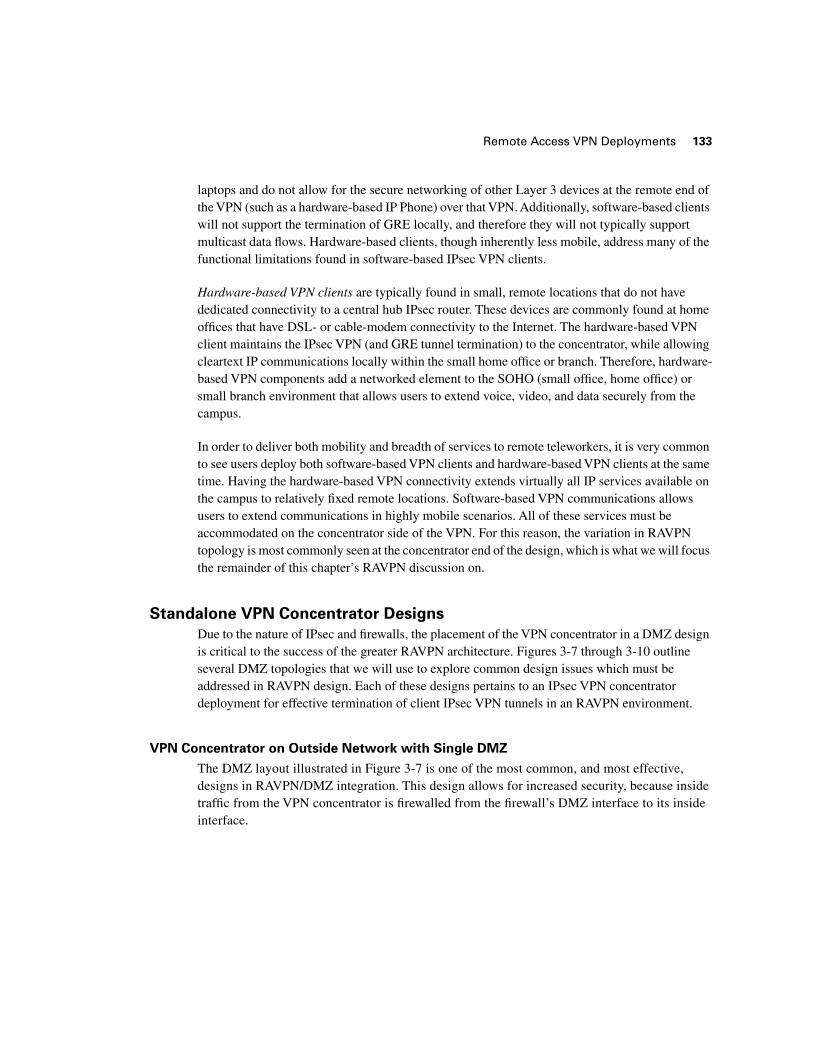
Figure 3-7 VPN Concentrator Placement in Single-DMZ Design
Also, the firewall can add an additional layer of proxy authentication AAA authentication in conjunction with an ACS server located on the inside network, offering a comprehensive authentication, authorization, and accounting solution for traffic types all the way up to Layer 7. The processing of traffic inbound from the DMZ can be further inspected for network attacks using either the PIX IOS-based signature set or a compatible, more comprehensive, signature set maintained on an external Network Intrusion Detection Systems (NIDS) appliance.
As we will also see with the design in Figure 3-8, there are no IPsec-specific modifications that need to be added to the firewall ACL configuration. Likewise, there are no additional Network Address Translation (NAT) considerations to account for on the firewall. This design does, however, require marginally increased filtering capability on the firewall, as cleartext traffic from the IPsec VPN concentrator is now being processed on the DMZ interface on its way to the inside network.
VPN Concentrator and Firewall in Parallel
Placing the VPN concentrator in parallel with the firewall eliminates the possibility of human error when opening up holes in the firewall ACL to allow IPsec traffic from inbound VPN clients to the concentrator (as with the design illustrated in Figure 3-10). Figure 3-8 provides an illustration of a standard DMZ design that places the VPN concentrator in parallel with the firewall.
ServiceProvider
Enterprise
Inside
DMZ 1
Outside
Remote Access VPN Deployments 135
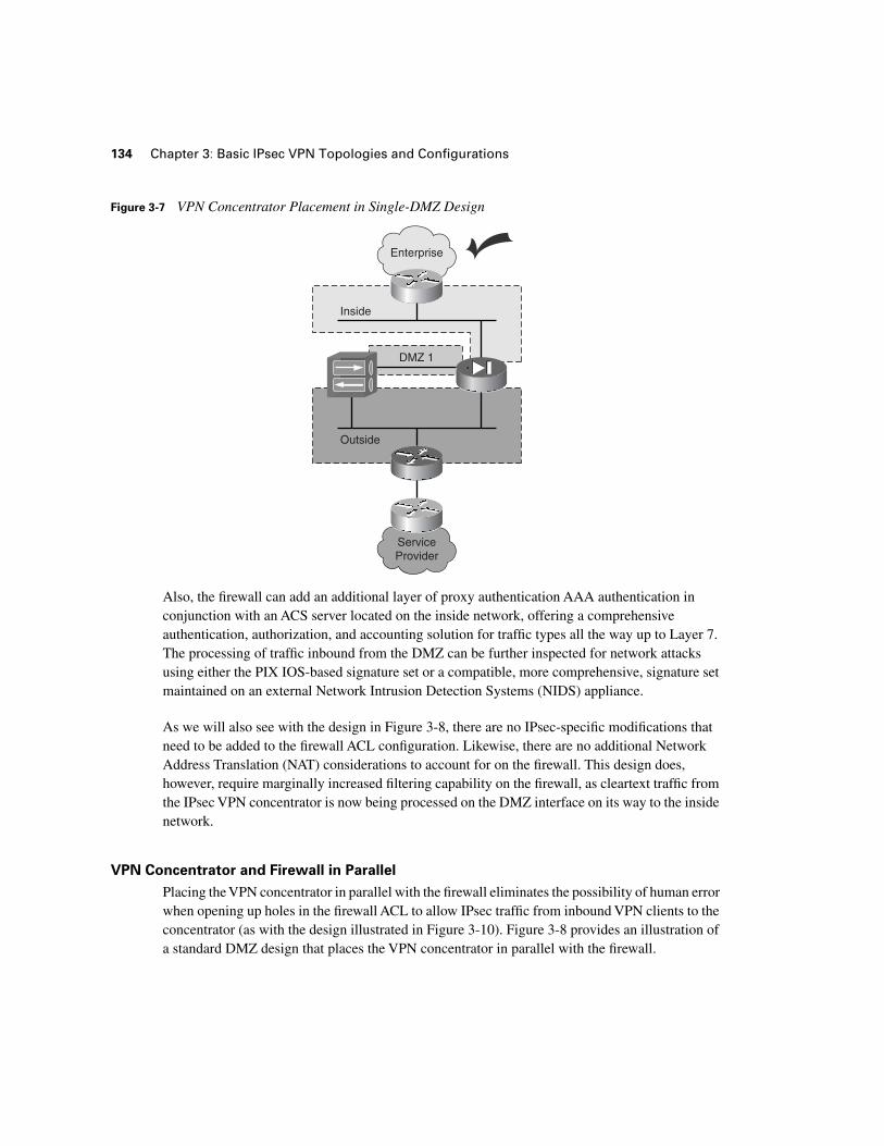
Figure 3-8 Parallel VPN Concentrator and Firewall DMZ Design
Additionally, this topology presents no computational overhead on the firewall for processing IPsec traffic in to the VPN concentrator. Instead, that traffic is focused solely on the VPN concentrator. Likewise, the concentrator is not burdened by non-VPN traffic, as would be the case if the concentrator were placed in series with the firewall on the outside network.
The parallel configuration described in the design of Figure 3-8 also simplifies the NAT configuration on both the firewall and the DMZ. Although IPsec itself can accommodate environ-ments where addresses are being translated, this topology eliminates the NAT processing of VPN traffic firewall and concentrator. Therefore, for RAVPN IPsec tunnels, the need for vendor-specific IPsec extensions such as NAT-T (IPsec NAT Transparency) is avoided.
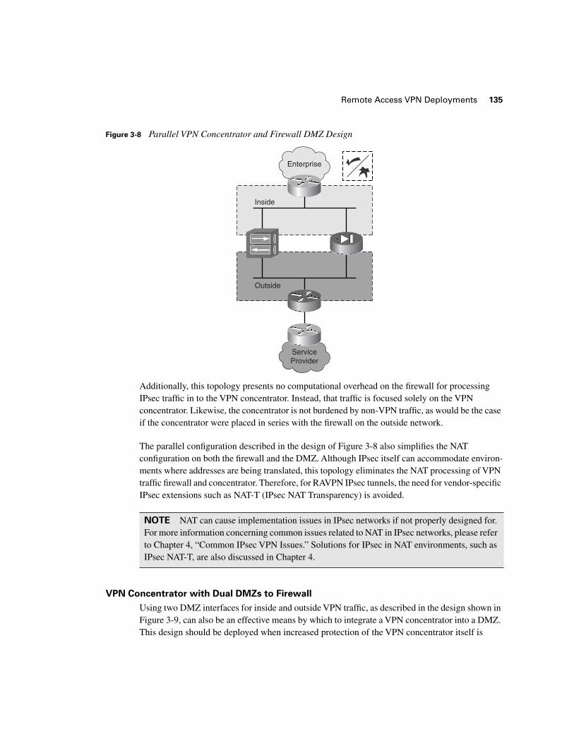
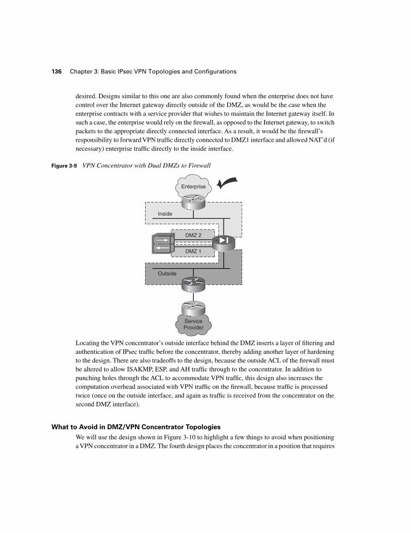
VPN Concentrator with Dual DMZs to Firewall
Using two DMZ interfaces for inside and outside VPN traffic, as described in the design shown in Figure 3-9, can also be an effective means by which to integrate a VPN concentrator into a DMZ. This design should be deployed when increased protection of the VPN concentrator itself is
NOTE NAT can cause implementation issues in IPsec networks if not properly designed for. For more information concerning common issues related to NAT in IPsec networks, please refer to Chapter 4, “Common IPsec VPN Issues.” Solutions for IPsec in NAT environments, such as IPsec NAT-T, are also discussed in Chapter 4.
ServiceProvider
Enterprise
Inside
Outside
136 Chapter 3: Basic IPsec VPN Topologies and Configurations
desired. Designs similar to this one are also commonly found when the enterprise does not have control over the Internet gateway directly outside of the DMZ, as would be the case when the enterprise contracts with a service provider that wishes to maintain the Internet gateway itself. In such a case, the enterprise would rely on the firewall, as opposed to the Internet gateway, to switch packets to the appropriate directly connected interface. As a result, it would be the firewall’s responsibility to forward VPN traffic directly connected to DMZ1 interface and allowed NAT’d (if necessary) enterprise traffic directly to the inside interface.
Figure 3-9 VPN Concentrator with Dual DMZs to Firewall
Locating the VPN concentrator’s outside interface behind the DMZ inserts a layer of filtering and authentication of IPsec traffic before the concentrator, thereby adding another layer of hardening to the design. There are also tradeoffs to the design, because the outside ACL of the firewall must be altered to allow ISAKMP, ESP, and AH traffic through to the concentrator. In addition to punching holes through the ACL to accommodate VPN traffic, this design also increases the computation overhead associated with VPN traffic on the firewall, because traffic is processed twice (once on the outside interface, and again as traffic is received from the concentrator on the second DMZ interface).
What to Avoid in DMZ/VPN Concentrator Topologies
We will use the design shown in Figure 3-10 to highlight a few things to avoid when positioning a VPN concentrator in a DMZ. The fourth design places the concentrator in a position that requires
DMZ 1
ServiceProvider
Enterprise
Inside
DMZ 2
Outside
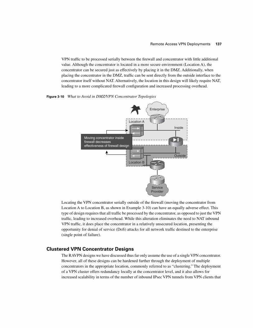
Remote Access VPN Deployments 137
VPN traffic to be processed serially between the firewall and concentrator with little additional value. Although the concentrator is located in a more secure environment (Location A), the concentrator can be secured just as effectively by placing it in the DMZ. Additionally, when placing the concentrator in the DMZ, traffic can be sent directly from the outside interface to the concentrator itself without NAT. Alternatively, the location in this design will likely require NAT, leading to a more complicated firewall configuration and increased processing overhead.
Figure 3-10 What to Avoid in DMZ/VPN Concentrator Topologies
Locating the VPN concentrator serially outside of the firewall (moving the concentrator from Location A to Location B, as shown in Example 3-10) can have an equally adverse effect. This type of design requires that all traffic be processed by the concentrator, as opposed to just the VPN traffic, leading to increased overhead. While this alteration eliminates the need to NAT inbound VPN traffic, it does place the concentrator in a relatively unsecured location, presenting the opportunity for denial of service (DoS) attacks for all network traffic destined to the enterprise (single point of failure).
Clustered VPN Concentrator Designs
The RAVPN designs we have discussed thus far only assume the use of a single VPN concentrator. However, all of these designs can be hardened further through the deployment of multiple concentrators in the appropriate location, commonly referred to as “clustering.” The deployment of a VPN cluster offers redundancy locally at the concentrator level, and it also allows for increased scalability in terms of the number of inbound IPsec VPN tunnels from VPN clients that
ServiceProvider
Enterprise
Inside
Location A
Location B
Outside
Moving concentrator insidefirewall decreaseseffectiveness of firewall design
138 Chapter 3: Basic IPsec VPN Topologies and Configurations
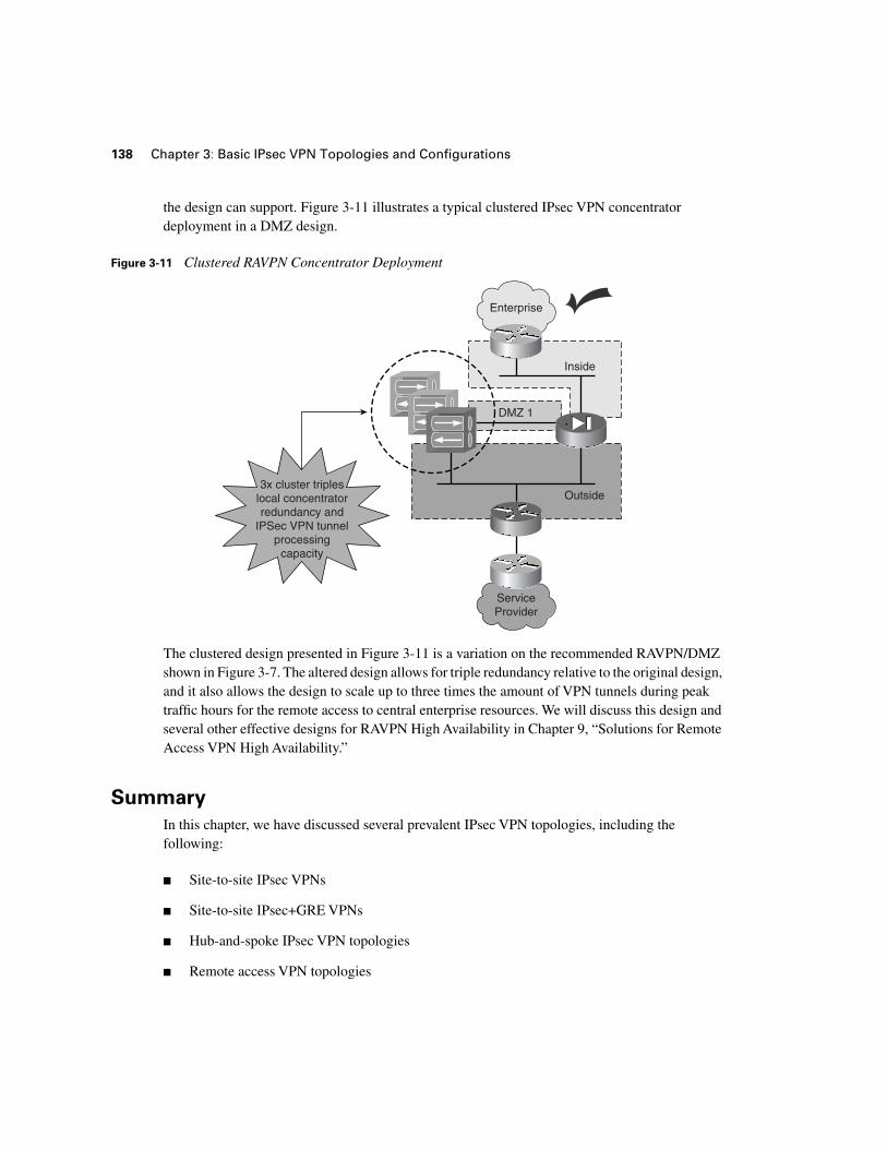
the design can support. Figure 3-11 illustrates a typical clustered IPsec VPN concentrator deployment in a DMZ design.
Figure 3-11 Clustered RAVPN Concentrator Deployment
The clustered design presented in Figure 3-11 is a variation on the recommended RAVPN/DMZ shown in Figure 3-7. The altered design allows for triple redundancy relative to the original design, and it also allows the design to scale up to three times the amount of VPN tunnels during peak traffic hours for the remote access to central enterprise resources. We will discuss this design and several other effective designs for RAVPN High Availability in Chapter 9, “Solutions for Remote Access VPN High Availability.”
Summary
In this chapter, we have discussed several prevalent IPsec VPN topologies, including the following:
■ Site-to-site IPsec VPNs
■ Site-to-site IPsec+GRE VPNs
■ Hub-and-spoke IPsec VPN topologies
■ Remote access VPN topologies
ServiceProvider
Enterprise
Inside
DMZ 1
Outside3x cluster triples
local concentratorredundancy and
IPSec VPN tunnelprocessing
capacity

Summary 139
At this point, you should be familiar with the basic layout of the preceding topologies, because they will serve as the basis for the explanation of more advanced concepts, such as local and geographic site-to-site IPsec HA and Remote Access VPN HA. Each of the preceding topologies is loosely grouped into a given design category, but you should be familiar with the design variants of each. For example, two important variations on a simple site-to-site IPsec topology are site-to-site IPsec VPN over a dedicated circuit and site-to-site IPsec VPN over a routed domain. The introduction of a routing protocol between the two crypto endpoints provides a material alteration to the VPN topology.
As with site-to-site IPsec VPN design variations, we have also covered several variations of hub-and-spoke IPsec VPN deployments, including the following:
■ Standard hub-and spoke design (no hub redundancy)
■ Clustered hub-and-spoke design to redundant hubs
■ Clustered hub-and-spoke design to redundant hubs with redundant spokes
Our discussion in this chapter of the basic advantages to each of the preceding hub-and-spoke variations will provide useful context when discussing resilient IPsec VPN design strategies in future chapters.
Finally, we have introduced several common DMZ designs with various IPsec VPN concentrator placement alternatives. These design alternatives included the following:
■ Standalone VPN concentrator DMZ design
■ Parallel VPN concentrator and firewall DMZ design
■ Dual DMZ VPN concentrator design
■ Serial VPN concentrator placement on inside firewall interface
At this point, you should have a basic familiarity with VPN concentrator placement in a firewalled DMZ design, as well as a basic understanding of the dangers of placing IPsec VPN concentrators serially inside a firewalled domain. We raised the advantages and disadvantages of each design in preparation for discussing remote access VPN HA concepts in Chapter 9,” Solutions for Remote Access VPN High Availability.”