Embed Size (px)
Citation preview

Basic information on the surgical and prosthetic procedures for the Straumann® Bone Level Tapered Implant ∅ 2.9 mm SC
Straumann® Bone Level Tapered Implant
490.073.indd 1 17/08/16 09:02

About this guide
The Basic information on the surgical procedures for the Straumann® Bone Level Tapered Implant ∅ 2.9 mm SC provides dental practitioners and related specialists with the essential steps re-garding surgical treatment and procedures for the Straumann® Bone Level Tapered Implant.
It is assumed that the user is familiar with placing dental implants. Not all detailed information will be found in this guide. Reference to existing Straumann procedure manuals will be made throughout this document.
Some items of the Straumann® Dental Implant System are not available in all countries.
490.073.indd 2 17/08/16 09:02
1
Content
1 The Straumann® Bone Level Tapered Implant 2
2 Implant system features and benefits 3
3 Indications 4
4 Planning 54.1 Preoperative planning 5
4.2 Planning aids 8
5 Surgical procedure 95.1 Workflow 9
5.2 Implant bed preparation 10
5.3 Implant placement 13
5.4 Soft tissue management 16
5.5 Healing period 17
6 Prosthetic procedure 186.1 Impression taking 18
6.2 Provisional preparation 18
6.3 Lab procedure 18
6.4 Chair-side procedure 19
6.5 Final restoration 20
7 Instruments 217.1 Depth marks on Straumann instruments 21
7.2 Cleaning and care of instruments 21
7.3 Straumann® Basic Surgical Cassette 22
8 Product reference list 23
9 Important guidelines 25
490.073.indd 1 17/08/16 09:02

2
1 The Straumann® Bone Level Tapered Implant
The Straumann® Dental Implant System offers two different implant lines, the Tissue Level Implants and the Bone Level Implants.
The Bone Level Implants are suitable for bone level treatments in combination with transgingi-val or subgingival healing. The rough implant surface extends to the top of the implant and the connection is shifted inwards.
The Straumann® Bone Level Tapered Implant features the established and clinically proven Straumann® Bone Control Design™ and the CrossFit® connection together with its correspond-ing prosthetic CrossFit® components from the Bone Level Implant product portfolio. It has an apically tapered and self-cutting design, making this implant particularly suitable for situations involving soft bone or fresh extraction sockets where primary stability is key.
Straumann® Dental Implant System
Soft Tissue Level Implants Bone Level Implants
S SP TE BL BLT
Straumann®Standard PlusImplant (SP)
Straumann®Standard
Implant (S)
Straumann®Tapered Effect
Implant (TE)
Straumann®Bone Level
Implant (BL)
Straumann®Bone Level
TaperedImplant (BLT)
The Straumann® Bone Level Tapered Implant comes with the ma-terial Roxolid® and the SLActive® surface*. A unified color code simplifies identification of instruments and implants for the four available endosteal diameters of ∅ 2.9 mm, ∅ 3.3 mm, ∅ 4.1 mm, and ∅ 4.8 mm.
Color coding
blue Endosteal implant diameter 2.9 mm
yellow Endosteal implant diameter 3.3 mm
red Endosteal implant diameter 4.1 mm
green Endosteal implant diameter 4.8 mm
* Not all products are available in all countries.
490.073.indd 2 17/08/16 09:02

3
2 Implant system features and benefits
The Straumann® Bone Level Tapered Implant comes with a number of excellent features de-signed for convenient handling as well as outstanding clinical performance. The following is to describe the specific features of the smallest diameter of the BLT implant line.
The CrossFit® connection of Bone Level Implants applies the know-how and benefits from the Straumann® synOcta® Morse taper connection to the connection requirements at bone level. The mechanically locking friction fit of the 15° conical-cylindrical CrossFit® connection with four internal grooves has excellent long-term stability under all loading conditions and virtually elim-inates screw loosening. The Bone Level Tapered Implants ∅ 2.9 mm feature the Small CrossFit® connection (SC), with specific secondary components. For the Small CrossFit® connection, Strau-mann offers Variobase® and CADCAM abutments designed to create the optimal restorative result with a simple and comprehensive portfolio.
CrossFit® connection makes handling easier and
provides confidence for component positioning.
Variobase® for crown for single-unit restorations of Straumann SC Implants.
SLActive® surface allows fast and predictable
osseointegration.
Bone Control Design™ allows optimized crestal bone preserva-tion and soft tissue stability.
Roxolid® is a unique material with excellent mechanical properties.
Apically tapered implant body design allows underpreparation and supports a high primary stability in soft bone.
Special retention features for a stable fitting.
490.073.indd 3 17/08/16 09:02

4
Specific indications for Straumann BLT 2.9 mm SC implants:
Implant type Minimal ridge width*
Minimal gap width**
Available lengths
BLT ∅ 2.9 mm SCRoxolid®SLActive®/SLA®
5 mm 5 mm 10 – 14 mm
To obtain more information about indications and contraindica-tions related to each implant, please refer to the corresponding instructions for use. Instructions for use can be found on www.ifu. straumann.com
Distinctive featuresSmall diameter implant for narrow interdental spaces and ridges in the anterior region specifically for upper lateral incisors and all lower incisors.
3 Indications
* Minimal ridge width: Minimal orofacial ridge width, rounded off to 0.5 mm ** Minimal gap width: Minimal mesial-distal gap width for a single-tooth restorati-
on, between adjacent teeth, rounded off to 0.5 mm
490.073.indd 4 17/08/16 09:02

5
4.1 Preoperative planning
The implant is the focal point of the restoration. It provides the basis for planning the surgical procedure. As the BLT Implant ∅ 2.9 mm SC is indicated mainly for esthetic areas, close commu-nication between the patient, dentist, surgeon and dental technician is imperative for achieving the desired final result.
To establish the topographical situation, the axial orientation, and the choice of implants, we recommend the following:
ѹ Prepare a wax-up/set-up on the previously prepared study cast and/or use an implant planning software like coDiagnostiX® in conjunction with the patient’s medical image data.
ѹ Define the type of superstructure.
The wax-up/set-up can later be used as the basis for a custom-made drill template and for a temporary restoration.
The implant diameter, implant type, position and number of implants should be selected indi-vidually, taking the anatomy and spatial circumstances (e.g. malpositioned or inclined teeth) into account. The measurements given here should be regarded as minimum guidelines. Only when the minimum distances are observed is it possible to design the restoration so that the necessary oral hygiene measures can be carried out.
The final hard and soft tissue response is influenced by the position between the implant and the proposed restoration. Therefore, it should be based on the position of the implant-abutment connection. The implant position can be viewed in three dimensions: ѹ Mesiodistal ѹ Orofacial ѹ Coronoapical
Note: The abutments should always be loaded axially. Ideally, the long axis of the implant is aligned with the cusps of the opposing tooth. Extreme cusp formation should be avoided. It can lead to unphysiological loading.
4 Planning
490.073.indd 5 17/08/16 09:02

6
4.1.1 Mesiodistal implant positionThe mesiodistal bone availability is an important factor for choosing the implant type and diam-eter as well as the inter-implant distances in case of multiple implants. The point of reference on the implant for measuring mesiodistal distances is always the shoulder being the most volumi-nous part of the implant. Note that all distances given in this chapter are rounded off to 0.5 mm. The following basic rules must be applied:
Rule 1: Distance to adjacent tooth at bone level: A minimal distance of 1.5 mm from the implant shoul-der to the adjacent tooth at bone level (mesial and distal) is recommended.
Rule 2: Distance to adjacent implants at bone level: A minimal distance of 3.0 mm between 2 adjacent im-plant shoulders (mesial and distal) is recommended.
≥ 1.5 mm
≥ 3.0 mm
490.073.indd 6 17/08/16 09:02

7
4.1.2 Orofacial implant position The facial and palatal bone layer must be at least 1 mm thick in order to ensure stable hard and soft tissue conditions. The minimal orofacial ridge widths for individual implant types are given in the indication in chapter 3. Within this limitation, a restoration-driven orofacial implant posi-tion and axis should be chosen so that screw-retained restorations are possible.
Caution: An augmentation procedure is indicated where the orofacial bone wall is less than 1 mm or a layer of bone is missing on one or more sides. This technique should be employed only by dentists who have adequate experience in the use of augmentation procedures.
4.1.3 Coronoapical implant position Straumann dental implants allow for flexible coronoapical implant positioning, depending on individual anatomy, implant site, the type of restoration planned, and preference. Straumann® Bone Level Tapered Implant is best set with the outer rim of the small 45° sloping edge (chamfer) at bone level.
Ideally, in the esthetic region, the implant shoulder should be positioned about 3 – 4 mm sub-gingival of the prospective gingival margin. The round markings in the Loxim™ Transfer Piece indicate the distance to the implant shoulder in 1 mm steps.
The layer of bone must be at least 1mm thick. Choose the orofacial implant position and axis so that the screw channel of the screw-retained restorations is located behind the incisal edge.
490.073.indd 7 17/08/16 09:02

8
4.2 Planning aids
The vertical bone availability determines the maximal allowable length of the implant that can be placed. For easier determination of the vertical bone avail-ability, we recommend the use of an X-ray Template (Art No. 025.0003)* with X-ray Reference Spheres (Art. No. 049.076V4).
4.2.1 Straumann® X-ray TemplatesThe Straumann® X-ray Templates are used for mea-surement and comparison. They also assist the user in selecting the suitable implant type, diameter and length. The X-ray Templates are available for the Straumann® Bone Level Implant and can be used for the Straumann® Bone Level Tapered Implant as well. Similar to the distortions that occur in X-rays, the implant dimensions are shown on the individual templates with the corresponding distortion factors (1:1 to 1.7:1).
Determining each magnification factor or scale is fa-cilitated by showing the X-ray reference sphere on the template. At first compare the size of the X-ray Refer-ence Sphere on the patient’s X-ray with the size of the reference sphere on the template. Superimpose the two pictures to find the correct scale. Then, determine the spatial relations around the implant position, and establish the implant length and insertion depth.
For more information regarding the preparation of the X-ray jig with the Reference Spheres, please see the Basic Information on the Surgical Procedures – Straumann® Dental Implant System, 152.754.
Warning: For Straumann® Bone Level Tapered Im-plants use only the X-ray Template specific to the Straumann® Bone Level Implant.
4.2.2 Straumann® Implant Distance IndicatorThe Straumann® Implant Distance Indicator is avail-able for Straumann® Bone Level Implants (Art. No. 026.0901) and can be used for the Straumann® Bone Level Tapered Implants as well.
The four discs of the Implant Distance Indicator display the shoulder diameters of the Bone Level Implants. The Implant Distance Indicator can be used to check the available space before starting the treatment or intraoperatively to mark the desired implant site.
Additionally, a single disc displaying the shoulder diameter of the ∅ 2.9 mm implant is available sep-arately. If it is needed to determine the distances in the anterior and reduced space areas, one of the discs delivered with article 026.0901 can be replaced by the BL ∅ 2.9 mm disc.
Implant Distance Indicator for Straumann® Bone Level Implants and Bone Level Tapered Implants
ѹ Art.-Nr.: 025.0044 ѹ Label: BL ∅ 2.9 ѹ Disk diameter: ∅ 2.9 mm ѹ Corresponding implants: Bone Level
Tapered Implants ∅ 2.9 mm
490.073.indd 8 17/08/16 09:02

9
For preparing the implant bed, the Straumann® Basic Surgical Cassette is used.The specific instruments to be used for the Straumann® Bone Level Tapered Implants ∅ 2.9 mm SC are marked with blue colored rings, except for the new Needle Drill which can be used in all protocols.
Depending on the bone density (type 1 = hard bone, type 4 = very soft bone) different drill proto-cols should be applied for the Straumann® Bone Level Tapered Implant. This provides the flexibil-ity to adjust the implant bed preparation to the individual bone quality and anatomical situation.
5.1 Workflow
Straumann® Bone Level Tapered ∅ 2.9 mm SC
5 Surgical procedure
Very hard boneType 1
Type 2
Type 3
Type 4
Hard bone
Soft bone
Very soft bone
Needle Drill ∅ 1.6 mm
Pilot Drill ∅ 2.2 mm
Profile Drill∅ 2.9 mm
BLT Tap ∅ 2.9 mm
rpm max 800 800 300 15
recommended steps
dense cortex only
490.073.indd 9 17/08/16 09:02

10
5.2 Implant bed preparation
For preparing the implant bed the Straumann® Basic Surgical cassette is used. For the Strau-mann® Bone Level Tapered Implant ∅ 2.9 mm SC a specific new instrument – a position indica-tor mimicking the oval Variobase® platform – is introduced in the procedure and it is used only during the basic implant bed preparation.
5.2.1 Position indicatorIntended useIf a restoration with a Variobase® Abutment is planned, the Position Indicator is an instrument used to ensure the correct positioning of the implant during implant bed preparation and to indi-cate the space taken by the abutment platform. It is made of titanium and delivered non-sterile and must be sterilized prior to use.
Characteristics
After opening the gingiva, the implant bed preparation begins with the preparation of the al-veolar ridge (Step 1) and the marking of the implantation site with a Round Bur and/or with a Needle Drill (Step 1), followed by the implant bed preparation with the Needle Drill and BLT Pilot Drill (Step 2 and 3),. The implant bed is widened in the cortical layer with the SC BLT Profile Drill (Step 4) and the threads are precut with the SC BLT Tap (Step 5).
Laser marked platform
Representation of different variobase gingiva heights
Product indentification
Representation of Variobase platform
490.073.indd 10 17/08/16 09:02

11
Step 1: Prepare alveolar ridge and mark implant positionCarefully reduce and smooth a narrow tapering ridge with a large Round Bur. This will provide a flat bone surface and a sufficiently wide area of bone. Mark the implantation site determined during the implant position planning with the ∅ 1.4 mm Round Bur and/or the ∅ 1.6 mm Needle Drill
Note: This step might be not applicable or different depending on the clinical situation (e.g. fresh extraction socket).Note: If the Distance Indicator is used together with the Needle Drill to mark the implant position, make sure not to drill more than 3mm in order to avoid any collision between the Needle Drill and the Distance Indicator.Caution: Handling with care at all times is recommended to avoid needlesticks.
Step 2 – Implant axis and depthFor ∅ 2.9 mm implants, mark the implant axis with the Needle Drill to a maximum depth of 6mm. Use the needle drill to check the axis orientation.
Drill the implant bed to the final depth with the Needle Drill, while correcting unsatisfactory implant axis orientation if necessary. Use the Needle Drill to check the implant axis and preparation depth.For ∅ 2.9 mm implants in very soft bone (type 4), the implant bed preparation ends here.
Caution: At this point take an X-ray, particularly with vertically re-duced bone availability.
Step 3 – Widen implant bed to ∅ 2.2 mmWith the ∅ 2.2 mm BLT Pilot Drill, drill to a depth of about 6 mm. Insert the ∅ 2.2 mm Alignment Pin to check for correct implant axis orientation. Use the ∅ 2.2 mm BLT Pilot Drill to prepare the implant bed to final preparation depth.
If necessary, correct any unsatisfactory implant axis orientation. Use the ∅ 2.2 mm Alignment Pin again to check the implant axis and preparation depth.
For ∅ 2.9 mm implants, also use the Position Indicator to check the available space for the future prosthetic solution, if a restoration with a Variobase® Abutment is planned. The implant bed prepara-tion for those implants in soft bone (type 3) ends here.
1
2
3
800 rpm
800 rpm
800 rpm
490.073.indd 11 17/08/16 09:02
12
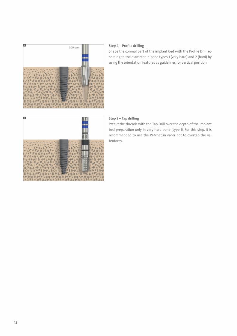
Step 4 – Profile drilling Shape the coronal part of the implant bed with the Profile Drill ac-cording to the diameter in bone types 1 (very hard) and 2 (hard) by using the orientation features as guidelines for vertical position.
Step 5 – Tap drilling Precut the threads with the Tap Drill over the depth of the implant bed preparation only in very hard bone (type 1). For this step, it is recommended to use the Ratchet in order not to overtap the os-teotomy.
4
5
300 rpm
490.073.indd 12 17/08/16 09:02

13
5.3 Implant placement
A Straumann implant can be placed with the handpiece or manually with the Ratchet. A maximum speed of 15 rpm is recommended.
Note: Straumann® Bone Level Tapered Implants must be rotationally oriented for both, handpiece and Ratchet insertion (see Step 4).
The following instructions show how a Straumann® Bone Level Tapered Implant ∅ 2.9 mm SC is placed with the Ratchet and/or handpiece.
For narrow interdental spaces, new adapters with an outer diameter of 4.0 mm will be available for both Ratchet and handpiece that will fit the new Loxim™ for the Straumann® Bone Level Tapered ∅ 2.9 mm SC.
5.3.1 Transfer pieceThe Bone Level Tapered Implants are delivered with the Loxim™ Transfer Piece, which is connected to the implant with a snap-in mounting.
Features Benefits
Snap-in mounting …… for easy handling without
counter-maneuvering
Blue color … … for high visibility
Compact dimensions … … for easy access
Height markings … … for correct implant placement
Pre-determined breaking point …
… avoids bone overcompression
490.073.indd 13 17/08/16 09:02

14
Step 1 – Attach Adapter Hold the enclosed part of the implant carrier. Attach the Ratchet Adapter/Handpiece Adapter to the Loxim™. You hear a click when the Adapter is at-tached correctly.
Step 2 – Remove implant from the carrier Simultaneously, pull down the implant carrier and lift the implant out of the implant carrier (keep your arms steady).
Step 3 – Place implant Place the implant with the Ratchet/Handpiece Adapter into the implant bed. And use the Ratchet and/or Hand-piece to move the implant into its final position turning it clockwise.
2
3 3
2
2 2
490.073.indd 14 17/08/16 09:02
15
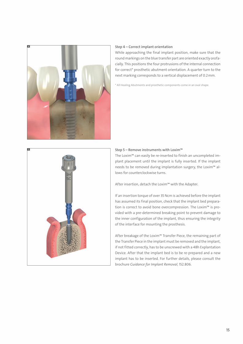
Step 4 – Correct implant orientation While approaching the final implant position, make sure that the round markings on the blue transfer part are oriented exactly orofa-cially. This positions the four protrusions of the internal connection for correct* prosthetic abutment orientation. A quarter turn to the next marking corresponds to a vertical displacement of 0.2 mm.
* All Healing Abutments and prosthetic components come in an oval shape.
Step 5 – Remove instruments with Loxim™ The Loxim™ can easily be re-inserted to finish an uncompleted im-plant placement until the implant is fully inserted. If the implant needs to be removed during implantation surgery, the Loxim™ al-lows for counterclockwise turns.
After insertion, detach the Loxim™ with the Adapter.
If an insertion torque of over 35 Ncm is achieved before the implant has assumed its final position, check that the implant bed prepara-tion is correct to avoid bone overcompression. The Loxim™ is pro-vided with a pre-determined breaking point to prevent damage to the inner configuration of the implant, thus ensuring the integrity of the interface for mounting the prosthesis.
After breakage of the Loxim™ Transfer Piece, the remaining part of the Transfer Piece in the implant must be removed and the implant, if not fitted correctly, has to be unscrewed with a 48h Explantation Device. After that the implant bed is to be re-prepared and a new implant has to be inserted. For further details, please consult the brochure Guidance for Implant Removal, 152.806.
4
5
490.073.indd 15 17/08/16 09:02

16
5.4 Soft tissue management
The Straumann® Bone Level Tapered Implant ∅ 2.9 mm SC puts a strong emphasis on esthetic considerations.It offers tailor-made solutions that allow for natural soft tissue shaping and maintenance for its indications. A versatile portfolio of healing and temporary abutments is available.
Esthetic results are crucially determined by successful soft tissue management. To optimize the soft tissue management process, various components with Consistent Emergence Profiles™ are available in the prosthetic portfolio of the Straumann® BLT Implant ∅ 2.9 mm SC. This applies for all healing abutments, the temporary abutments and the abutments for the final restoration. Thus, the emergence profiles are uniform throughout the treatment process.
5.4.1 Soft tissue management portfolio
Closure Screw Healing Abutments Temporary Abutments
490.073.indd 16 17/08/16 09:02
17
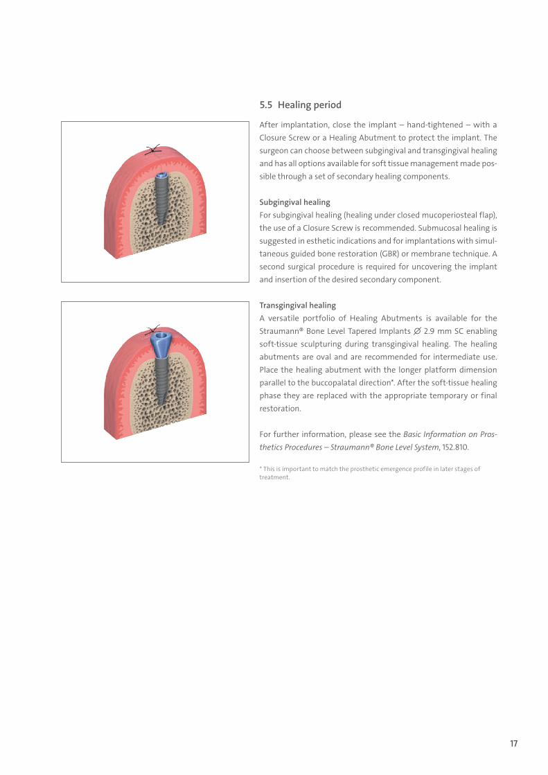
5.5 Healing period
After implantation, close the implant – hand-tightened – with a Closure Screw or a Healing Abutment to protect the implant. The surgeon can choose between subgingival and transgingival healing and has all options available for soft tissue management made pos-sible through a set of secondary healing components.
Subgingival healing For subgingival healing (healing under closed mucoperiosteal flap), the use of a Closure Screw is recommended. Submucosal healing is suggested in esthetic indications and for implantations with simul-taneous guided bone restoration (GBR) or membrane technique. A second surgical procedure is required for uncovering the implant and insertion of the desired secondary component.
Transgingival healing A versatile portfolio of Healing Abutments is available for the Straumann® Bone Level Tapered Implants ∅ 2.9 mm SC enabling soft-tissue sculpturing during transgingival healing. The healing abutments are oval and are recommended for intermediate use. Place the healing abutment with the longer platform dimension parallel to the buccopalatal direction*. After the soft-tissue healing phase they are replaced with the appropriate temporary or final restoration.
For further information, please see the Basic Information on Pros-thetics Procedures – Straumann® Bone Level System, 152.810.
* This is important to match the prosthetic emergence profile in later stages of treatment.
490.073.indd 17 17/08/16 09:02

18
6.1 Impression taking
ѹ Place the Impression Post accurately into the abutment and hand-tighten the Guide Screw.
ѹ Ensure correct positioning of the Impression Posts to ensure prop-er fit of the restoration. Make sure the engaging features of the impression components are correctly aligned and fully inserted into the implant to avoid any gaps.
ѹ Make perforations in the custom-made impression tray (light-cured resin) according to the individual situation so that the Posi-tioning Screw of the Impression Post sticks out visibly.
ѹ Take the impression using a standard elastomeric impression ma-terial (e.g. polyvinyl siloxane or polyether rubber). Uncover the screws before the material is set.
ѹ Once the material is set, loosen the Guide Screws and remove the tray.
ѹ In the dental lab, position and fix an Implant Analog to the impres-sion using the Guide Screw.
ѹ Fabricate the master cast. A gingival mask should always be used to ensure that the emergence profile is optimally contoured.
6.2 Provisional preparation
The SC Temporary Abutments offer the following characteristics: ѹ Narrow profile for narrow interdental spaces ѹ Reliable and precise fit ѹ High stability due to titanium alloy (TAN) material ѹ Small CrossFit® (SC) connection for engaging abutments
6.3 Lab procedure
Step 1 – Preparation ѹ Mount the Temporary Abutment on the master cast and mark the
appropriate heights according to the individual situation. ѹ Shorten the abutment as necessary, sandblast and coat with
opaquer to prevent from showing through. ѹ Screw the Temporary Abutment onto the Implant Analog (hand-
tight) and temporarily seal the screw channels (e.g. with cotton)
6 Prosthetic procedure
Temporary Abutment, TAN
Implant Analog & Repositionable Analog
1
490.073.indd 18 17/08/16 09:02

19
Step 2 – Creating the provisional ѹ Use a standard technique to fabricate the provisional. ѹ The retention elements ensure proper mechanical bonding of the
veneering material to the Temporary Abutment. ѹ Remove excess acrylic, re-open the screw channel and finish the
temporary restoration.
Step 3 – Inserting the provisionalSee Chair-side procedure Step 3.
6.4 Chair-side procedure
Step 1 – Preparation ѹ Mount the Temporary Abutment in patient’s mouth. ѹ Mark the appropriate heights according to the individual situation. ѹ Remove the abutment from the patient’s mouth. ѹ Prepare the abutment as explained in Step 1 of the lab procedure.
Step 2 – Creating the provisional ѹ Use a standard technique to fabricate the provisional (e.g. prefabricated crown
form or vacuum-formed ѹ sheet technique). ѹ Remove excess acrylic, re-open the screw channel and finish the temporary restoration.
Step 3 – Inserting the provisional ѹ Clean and disinfect the polished temporary restoration, place it on the implants and tight-
en the screw between 15 Ncm and 35 Ncm (depending on implant stability) using the SCS Screwdriver along with the Ratchet and the Torque Control Device.
ѹ Cover the screw head with absorbent cotton or gutta-percha and seal the screw channel with temporary veneering material (e.g. composite).
Note ѹ Do not use for longer than 180 days. ѹ Place temporary restorations out of occlusion. ѹ The Temporary Abutment can be shortened vertically no more than 6 mm with usual tools
and technique. ѹ The devices are provided non-sterile and are for single use only. ѹ The abutment must be secured against aspiration. ѹ Refer to the veneer material manufacturer for information regarding the disinfectants that
can be used. ѹ The abutments can be processed with cleaning/disinfecting agents such as Ethanol, Tego
Cid 2 %, Micro 10 + 4 %, Cidex OPA pure and Grotanat 2 %. ѹ The abutment can be steam-sterilized (134 °C/5 min).
2
490.073.indd 19 17/08/16 09:02

20
6.5 Final restoration
Digital procedureStraumann® CARES® CADCAM offers customized patient solutions for cement-re-tained crowns. Available in titanium alloy (TAN) with a superstructure of a variety of materials such as zerion®, coron® and polycon®, etc.
For further information regarding Straumann® CARES® Implant-borne prosthet-ics, please see the brochure Basic Information on the Straumann® CARES® Im-plant-borne Prosthetic Procedures –Straumann® CARES® Implant-borne Prosthetic, 152.822.
Conventional procedureThe SC Variobase® has an oval platform shape in order to better fit in reduced interdental spaces. It comes in 3 different gingiva heights to offer more prosthetic flexibility.
For more information on the Straumann® Variobase®, please refer to the brochure Basic information on Straumann® Variobase®, Art.-No. 490.062.
Step 1 – Fabricating the master cast and wax-up ѹ Fabricate the master cast including a gingiva mask with the corresponding
Implant Analog. ѹ For optimal esthetic planning, model a full anatomical wax-up.
Step 2 – Fabricating the crown ѹ Select the Burn-out Coping and place it on the Variobase®. ѹ Fabricate the superstructure using standard modeling methods. ѹ Cast the framework using the standard casting methods. ѹ Adjust the framework so that it can be attached to the Variobase® and into
the Analog. ѹ Veneer the superstructure.
490.073.indd 20 17/08/16 09:02

21
7.1 Depth marks on Straumann instruments
Straumann instruments have depth marks in 2 mm intervals that correspond to the available implant lengths. The bold mark on drills represents 10 mm and 12 mm, whereas the lower edge of the mark corresponds to 10 mm and the upper edge to 12 mm.
Warning: Due to the function and design of the drills, the drill tip is 0.4 mm longer than the insertion depth of the implant.
Careful treatment of all instruments is of the utmost importance. Even slight damage for instance to the drill tips (e.g., when the drills are “thrown” into a bowl of water) impairs cutting performance and thus the clinical result. With correct and careful care, the high quality of the material and excellent workmanship ensure that the rotating instruments can be used repeatedly (up to a maximum of ten times is recom-mended).
Instruments with high cutting performance are a basic requirement for successful implantation. The following should therefore be observed:
ѹ Never allow instruments to land on their tips. ѹ Use each instrument only for its intended purpose. ѹ Never let surgical residues (blood, secretion, tissue
residues) dry on an instrument; clean immediately after surgery.
ѹ Thoroughly clean off incrustations with soft brush-es only. Disassemble instruments, clean cavities es-pecially well.
ѹ Never disinfect, clean (also ultrasound) or sterilize instruments made of different materials together.
ѹ Use only cleaning agents and disinfectants intend-ed for the material and follow the instructions for use of the manufacturer.
ѹ Rinse disinfectants and cleaning agents very thor-oughly with water.
ѹ Never leave or store instruments moist or wet.
For more detailed information, please see the bro-chure Care and Maintenance of Surgical and Prosthetic Instruments, 152.008.
7.2 Cleaning and care of instruments
7 Instruments
12 mm
0.4 mm
490.073.indd 21 17/08/16 09:02

22
7.3 Straumann® Basic Surgical Cassette
The Basic Surgical Cassette is used for the secure storage and sterilization of the surgical instruments and auxiliary instruments of the Straumann® Dental Implant System. The Basic Surgical Cassette is made of a highly shock-proof thermoplastic, which has been proven for years in the medical area and is suitable for frequent sterilization in the autoclave.
490.073.indd 22 17/08/16 09:02

23
8 Product reference list
Art. No. Article
021.0010 BLT ∅ 2.9 mm SC, SLActive® 10 mm, Roxolid®, Loxim™
021.0012 BLT ∅ 2.9 mm SC, SLActive® 12 mm, Roxolid®, Loxim™
021.0014 BLT ∅ 2.9 mm SC, SLActive® 14 mm, Roxolid®, Loxim™
021.0110 BLT ∅ 2.9 mm SC, SLA® 10 mm, Roxolid®, Loxim™
021.0112 BLT ∅ 2.9 mm SC, SLA® 12 mm, Roxolid®, Loxim™
021.0114 BLT ∅ 2.9 mm SC, SLA® 14 mm, Roxolid®, Loxim™
024.0006S SC Closure Cap, ∅ 2.4 mm, H 0.5 mm, Ti
024.0007S SC Healing Abutment, conical, oval, H 2 mm, Ti
024.0008S SC Healing Abutment, conical, oval, H 3.5 mm, Ti
024.0009S SC Healing Abutment, conical, oval, H 5 mm, Ti
024.0010S SC Healing Abutment, conical, oval, H 6.5 mm, Ti
025.0020 SC Impression Post Closed Tray with 1 guide screw & 2 caps, L 19 mm, TAN/POM
025.0021 SC Impression Post Open Tray, short
025.0022 SC Impression Post for open tray, with guide screw, L 24 mm, TAN
025.0023 SC Implant Analog, L 12 mm, TAN
025.0024 SC Repositionable Implant Analog, L 17 mm, stainless steel
025.0031 SC Basal Screw B, L 7 mm, TAN
024.0011 SC Temporary Abutment, crown, oval, GH 1 mm, TAN
024.0015 SC Temporary Abutment, crown, oval, GH 2 mm, TAN
024.0016 SC Temporary Abutment, crown, oval, GH 3 mm, TAN
022.0038 SC Variobase®, with screw, oval, GH 1 mm, TAN
022.0039 SC Variobase®, with screw, oval, GH 2 mm, TAN
022.0040 SC Variobase®, with screw, oval, GH 3 mm, TAN
023.0011 SC Burn-out Coping, for Variobase®, POM
023.0011V4 SC Burn-out Coping, for Variobase®, POM, packaging unit 4 pieces
025.0029 SC Polishing Aid, L 16 mm, stainless steel
025.0025 SC CARES® Mono Scanbody, ∅ 3.5 mm, H 10 mm, PEEK/TAN
490.073.indd 23 17/08/16 09:02

24
Art. No. Article
026.0054 Needle Drill, short, ∅ 1.6 mm, L 33 mm, stainless steel
026.0056 Needle Drill, long, ∅ 1.6 mm, L 41 mm, stainless steel
026.0058 SC Position Indicator, oval, L 10 mm, Ti
026.0061 BLT Profile Drill, short, ∅ 2.9 mm, L 25 mm, stainless steel
026.0062 BLT Profile Drill, long, ∅ 2.9 mm, L 33 mm, stainless steel
026.0063 BLT Tap, ∅ 2.9 mm, L 25 mm, stainless steel/TAN
026.0073 Release Aid S for Loxim™
026.0066 SC Guiding Cylinder, for ∅ 2.9 mm, stainless steel
026.0068 Explantation Drill, medium, for ∅ 2.9 mm, L 37.5 mm, stainless steel
026.0069 Explantation Drill, long, for ∅ 2.9 mm, L 40 mm, stainless steel
026.0072 48h Explantation Device, for ∅ 2.9 mm, L 29.7 mm, stainless steel
025.0042 Adapter for Handpiece, long, L 34 mm, stainless steel
025.0043 Adapter for Ratchet, long, L 28 mm, stainless steel
025.0044 Implant Distance Indicator Additional Component, for BLT ∅ 2.9 mm, Ti
490.073.indd 24 17/08/16 09:02

25
9 Important guidelines
Please notePractitioners must have appropriate knowledge and instruction in the handling of the Straumann CADCAM products or other Strau-mann products (“Straumann Products”) for using the Straumann Products safely and properly in accordance with the instructions for use.
The Straumann Product must be used in accordance with the in-structions for use provided by the manufacturer. It is the practi-tioner’s responsibility to use the device in accordance with these instructions for use and to determine, if the device fits to the indi-vidual patient situation.
The Straumann Products are part of an overall concept and must be used only in conjunction with the corresponding original com-ponents and instruments distributed by Institut Straumann AG, its ultimate parent company and all affiliates or subsidiaries of such parent company (“Straumann”), except if stated otherwise in this document or in the instructions for use for the respective Strau-mann Product. If use of products made by third parties is not rec-ommended by Straumann in this document or in the respective instructions for use, any such use will void any warranty or other obligation, express or implied, of Straumann.
AvailabilitySome of the Straumann Products listed in this document may not be available in all countries.
Caution In addition to the caution notes in this document, our products must be secured against aspiration when used intraorally.
ValidityUpon publication of this document, all previous versions are super-seded.
Documentation For detailed instructions on the Straumann Products contact your Straumann representative.
Copyright and trademarksStraumann® documents may not be reprinted or published, in whole or in part, without the written authorization of Straumann. Straumann® and/or other trademarks and logos from Straumann® mentioned herein are the trademarks or registered trademarks of Straumann Holding AG and/or its affiliates.
Explanation of the symbols on labels and instruc-tion leaflets
Batch code
Catalogue number
Sterilized using irradiation
…min.
Lower limit of temperature
…max.
Upper limit of temperature
…max.
…min.
Temperature limitation
Caution: U.S. federal law restricts this de-vice to sale by or on the order of a dental professional.
Do not re-use
Non-sterile
Caution, consult accompanying documents
Use-by date
Keep away from sunlight
Straumann Products with the CE mark fulfill the requirements of the Medical Devices Directive 93/42 EEC
Consult instructions for use Please follow the link to the e-IFU www.ifu.straumann.com
490.073.indd 25 17/08/16 09:02

International Headquarters Institut Straumann AG Peter Merian-Weg 12 CH-4002 Basel, Switzerland Phone +41 (0)61 965 11 11 Fax +41 (0)61 965 11 01 www.straumann.com
© Institut Straumann AG, 2016. All rights reserved.Straumann® and/or other trademarks and logos from Straumann® mentioned herein are the trademarks or registered trademarks of Straumann Holding AG and/or its affiliates.
49
0.07
3/en
/D/0
0 08
/16
490.073.indd 26 17/08/16 09:02