Embed Size (px)
Citation preview

STUDY COURSEfor Home Appliances
HOW TO READ:• WIRING DIAGRAM SYMBOLS• TERMINAL CODES• WIRING DIAGRAMS
Module 2LIT 787740 Rev. C
BASIC ELECTRICITY
CABINET GROUND
STARTER
BALLAST
FLUORESCENTLAMP
BK W
1
S
For more help, go to Fixitnow.com Samurai Appliance Repair Man

All rights reserved. No portion of this book may be reproduced in any form withoutwritten permission from WHIRLPOOL CORPORATION.
© 1989, 1993, 2000 WHIRLPOOL CORPORATION
WHIRLPOOL CORPORATION does not assume any responsibilityor any liability in connection with the use of this manual.
® The trademarks WHIRLPOOL , , , and FSP are registeredtrademarks of Whirlpool Corporation.
For more help, go to Fixitnow.com Samurai Appliance Repair Man

INTRODUCTION
The material presented in this module is intended to provide you with an understanding of thefundamentals of electricity as applied to major appliances.
Major appliances have become more sophisticated, taking them out of the screwdriver and pliers category.Their electrical circuits include several different types of automatic controls, switches, heaters, valves, etc..Semiconductors, solid-state controls, and other components usually associated with radio and televisionelectronic circuits, are being engineered into automatic washers, dryers, dishwashers, and refrigerators.
The appliance technician is emerging into a professional status of his own. He must prepare himself nowto be able to perform his duties today as well as to retain his professionalism in the future.
No longer is on-the-job training sufficient to prepare technicians for the complicated procedures requiredfor todays sophisticated appliances. This training can best be obtained through organized classroom studyand application. However, much of the knowledge necessary to service todays appliances can be obtainedthrough study courses. Completion of this and other courses will provide you with sufficient understanding ofappliances and their operation to enable you to do minor service. It will also serve as a valuable steppingstone to more advanced study and on-the-job training to improve your servicing skills.
Information contained in this module is used on WHIRLPOOL® appliances.
1For more help, go to Fixitnow.com Samurai Appliance Repair Man

TABLE of CONTENTS
PAGE
CHAPTER 1 ..............................................................................................3Wiring Diagram Symbols
CHAPTER 2 ..............................................................................................6Terminal Codes
CHAPTER 3 ..............................................................................................7Wiring Diagrams
*TEST ............................................................See Test Book LIT787743
*NOTE: We recommend taking the TEST for MODULE 2, rightafter studying it.
2For more help, go to Fixitnow.com Samurai Appliance Repair Man

CHAPTER 1
WIRING DIAGRAM SYMBOLS
3
These wiring diagram symbols are commonly used in most wiring diagrams. Study each symbol so you canidentify them by sight.
THERMOSTATSWITCHES
RELAY(Show Device Used)
(Momentary or Spring Return)
MERCURY SWITCH
NORMALLY CLOSED (SPST)(Single-Pole, Single-Throw)
NORMALLY OPEN
TRANSFER (SPDT)(Single-Pole, Double-Throw)
MULTI-POSITION
NUMBER OF TERMINALS
N.O.(Normally Open)
N.C.(Normally Closed)
INTEGRAL SWITCH(Timer, Clock, Etc.)
N.O. (CIRCUIT CLOSING)(Normally Open)
N.C. (CIRCUIT OPENING)(Normally Closed)
SPDT(Single-Pole, Double-Throw)
SPST(Single-Pole, Single-Throw)
SPDT(Single-Pole, Double-Throw)
OPERATES ONTEMPERATURE RISE
OPERATES ONTEMPERATURE FALL
N.O.(Normally Open)
N.C.(Normally Closed)
DOUBLE THROW
ADJUSTABLE
COIL-OPERATED
HEAT-OPERATED
DOUBLE-POLE
MANUAL AND MECHANICAL
AUTOMATIC SWITCH
PUSHBUTTON SWITCH
TWO CIRCUIT
For more help, go to Fixitnow.com Samurai Appliance Repair Man

4
WIRING DIAGRAM SYMBOLSMOTORSTEMPERATURE ACTUATED
MISCELLANEOUS
MASTER OR CONTROL
LAMPS
CIRCUIT PROTECTORS
SWITCH
CLOSES ONTEMPERATURE RISE
OPENS ONTEMPERATURE RISE
OFF
HI
MED
LOL1 2 3 5 6 1
Typical Example
(Number of Positionsand Internal Contact
Operation as Required)
INCANDESCENT
BALLAST
FLUORESCENT
NEON
CIRCUIT BREAKER
CIRCUIT BREAKERW/THERMAL O.L.
FUSE
TMTIMER OR CLOCK
SINGLE-SPEED
COMPRESSORC
R
S
ADJUSTABLE COMPONENT(Arrow Drawn thru
Component at Approx. 45˚)
OPERATING COIL(Solenoid Relay)
BALLAST
STARTER
RESISTORor HEATER
CAPACITOR
CAPACITOR(Non-Polarized)
HEATER
TRANSFORMER
TWO-SPEED
THREE-SPEED
THERMAL FUSE
GERMICIDAL
For more help, go to Fixitnow.com Samurai Appliance Repair Man

5
WIRING DIAGRAM SYMBOLS
N.O.(Normally Open)
N.C.(Normally Closed)
BUZZERS LINES AND CONNECTIONS
SENSOR(Moisture)
CENTRIFUGAL SWITCH
ADJUSTABLE
INTERNAL CONDUCTOR
EXTERNAL or HARNESS WIRE
OPTIONAL or ALTERNATE CIRCUIT
CROSSOVER
JUNCTION
PERMANENT CONNECTION
TERMINAL
SHIELD
GROUND (EARTH)
GROUND (CHASSIS)
GROUNDED SERVICE CORD(3-Prong Plug)
SERVICE CORD(2-Prong Plug)
MECHANICAL CONNECTION
SEPARABLE CONNECTION
○ ○ ○ ○ ○ ○ ○ ○ ○ ○
LIMIT SWITCH
BELL
THERMOCOUPLE
PRESSURE SWITCHS.P.D.T.
HUMIDISTAT
MAGNETRON
THERMISTOR
For more help, go to Fixitnow.com Samurai Appliance Repair Man

6
Terminal Color Codes Harness Wire Color
BK ................................................................................................................BlackBK-Y ........................................................................... Black with Yellow Tracer
BR .............................................................................................................. BrownBR-O or BR-OR ....................................................... Brown with Orange TracerBR-R .............................................................................. Brown with Red TracerBR-W ......................................................................... Brown with White Tracer
BL or BU ...................................................................................................... BlueBL-BK or BU-BK .......................................................... Blue with Black TracerBL or BU-G or BL or BU-GN .......................................Blue with Green TracerBL or BU-O or BL or BU-OR .................................... Blue with Orange TracerBL-Y or BU-Y ...............................................................Blue with Yellow Tracer
G or GN ...................................................................................................... GreenG-BK or GN-BK .......................................................... Green with Black TracerG-Y or GN-Y .............................................................. Green with Yellow Tracer
GY .................................................................................................................GrayGY-P or GY-PK .............................................................. Gray with Pink Tracer
LBU .................................................................................................... Light Blue
O or OR.....................................................................................................OrangeO-BK or OR-BK ........................................................ Orange with Black Tracer
P or PK ......................................................................................................... Pink
P or PR ...................................................................................................... PurpleP-BK or PR-BK .......................................................... Purple with Black Tracer
R......................................................................................................................RedR-BK ................................................................................Red with Black TracerR-W ................................................................................. Red with White Tracer
T or TN .......................................................................................................... TanT-R or TN-R ...................................................................... Tan with Red Tracer
V.................................................................................................................. Violet
W ................................................................................................................. WhiteW-BK ........................................................................... White with Black TracerW-BL or W-BU .............................................................. White with Blue TracerW-G or W-GN ............................................................. White with Green TracerW-O or W-OR ........................................................... White with Orange TracerW-R ................................................................................. White with Red TracerW-V ..............................................................................White with Violet TracerW-Y ............................................................................ White with Yellow Tracer
Y ................................................................................................................. YellowY-BK ........................................................................... Yellow with Black TracerY-G or Y-GN .............................................................. Yellow with Green TracerY-R ................................................................................. Yellow with Red Tracer
CHAPTER 2
TERMINAL CODESTerminal codes are found on all wiring diagrams. To help you identify the color codes, see the list below.
For more help, go to Fixitnow.com Samurai Appliance Repair Man

7
CHAPTER 3
WIRING DIAGRAMSAppliance circuits can be complex. In order to construct a diagram of these circuits, the different componentsand switches must be represented by symbols. The ability to read the symbols and a wiring diagram is one ofthe most important diagnostic tools for an appliance technician.
This lesson is designed to instruct in the reading, interpretation, and construction of wiring diagrams. It is inthe form of programmed instructions, which allows the student to work at their own pace and correct anyerrors immediately.
The answers to the following questions are found on pages 17-19.
1
A wiring diagram is similar to a road map.The lines on a
road map show you where you can travel. The lines on a
___________ diagram show where electric current can
travel.
2
When this symbol appears on a bottle of iodine
or other medicine, we know its contents to be poison. The
skull and crossbones may alert us to caution before we
notice the word “POISON.” The symbol may be recognized
quicker as a warning than the word. Thus the
stands for, or is a ____________ of, poison.
3
Other symbols which we often encounter are railroad
crossing markers , stop signs , and
yield the right of way signs . They are easily
recognized and are nationally known to stand for the same
thing every time. Railroad markers and stop signs are
______________ used in driving.
4
In this short course, symbols will he used to represent
parts (components) in wiring diagrams. At first it may
seem that a knowledge of symbols is unnecessary to “get
the job done,” but as you progress you will realize that to
“get the job done” quicker and better you should recognize
most electrical _______________ .
5
Pictorial wiring diagrams show pictures of electrical
components. Because they show “pictures” of the actual
component that they are called pictorial wiring ________ .
6
To interpret pictorial wiring diagrams you need little
special training since the components are represented
by _____________ .
STOP
YIELD
PICTUREOF
PLUG
PICTUREOF
LIGHT BULB
PICTUREOF
LIGHT SWITCH
PICTUREOF
PLUG
PICTUREOF
LIGHT BULB
PICTUREOF
LIGHT SWITCH
For more help, go to Fixitnow.com Samurai Appliance Repair Man

7
A simple wiring diagram is easy to follow when shown
pictorially. An example of this type of wiring diagram could
be like this:
The above is a _______________ wiring diagram.
8
The bulb will light when the door is opened if wired
as shown in this ___________ ___________ __________ .
But the same power cord supplies other components, too.
9
Pictorial wiring diagrams are easy to read when only a few
components are involved. Add more components and the
_____________ wiring diagram is harder to read.
10
The bulb, switch,plug, and wire wereeasy to follow in thelast diagram. How-ever, a quick look atthe pictorial at theright shows thatmore componentsmake the diagramharder to read.CIRCLE THEBULBS, SWITCH,AND PLUG IN THISPICTURE.
11
Many wiring labels show a pictorial and schematic wiring
diagram. The _______________ wiring diagram is more
compact, and it is easy to trace its wiring circuits.
12
Learning to read a schematic wiring diagram is like learn-
ing a new language, but since most wiring diagrams are
printed in the schematic language, we should learn to read
______________ wiring symbols.
13
Let’s start with something simple and learn how to read
schematic wiring diagrams. The first step is to associate
the electrical component with its appropriate symbol.
For example—This is anincandescentlight bulb:
The schematic symbolfor an incandescentlight bulb is:
DRAW THE SCHEMATICSYMBOL FOR LIGHT BULBIN THE ABOVE SQUARE.
14
We have shown the schematic symbolfor a bulb is:
Here is the schematic symbol for a switch:
It looks like a drawbridge.
DRAW THE SCHEMATICSYMBOL FOR A SWITCHIN THE ABOVE SQUARE.
15
A switch controls the flow of electric current. When the
switch is open like this: current cannot flow.
When the switch is _____________ like this:
current can flow.
16
When a switch opens, we say that the circuit is broken;
when a switch closes, we say that the circuit is made.
Please circle the switch in which the circuit is broken.
17
This is the symbol for a resistor . If a water
pipe were shaped like that, water would have trouble
getting through it, wouldn’t it? So now when you see
the symbol you know it is a ______________ .
18
A resistor can be used to create heat or reduce current flow.
Current reducing resistors will always be in series with
some other component. One purpose of a resistor is to limit
the amount of ______________ going to a component.
BULB
SWITCHPLUG
DOOR SWITCH
POWER CORD
MOTOR
FAN
HEATER
CABINETLIGHT
CABINETLIGHT
DOOR SWITCH
POWER CORD
MOTOR
FAN
HEATER
CABINET LIGHT
CABINET LIGHT
WALL PLUG
SCHEMATIC
LIGHT SWITCH
HEATER
LIGHT
MOTOR
MOTOR
8
A B
For more help, go to Fixitnow.com Samurai Appliance Repair Man
9
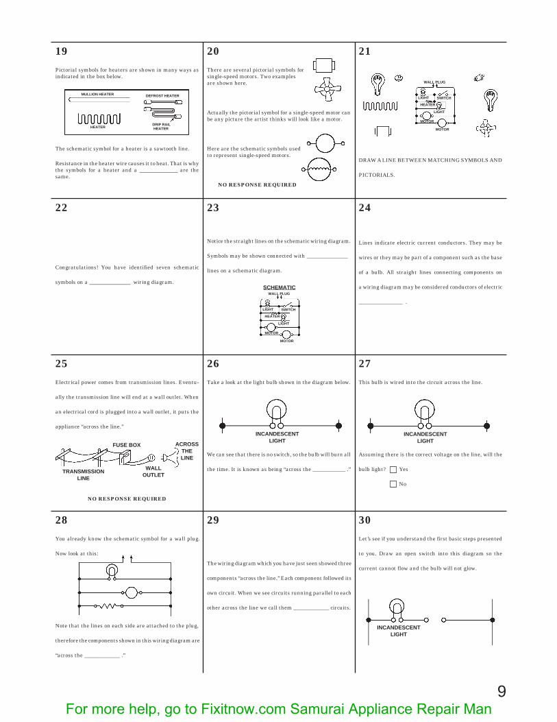
19
Pictorial symbols for heaters are shown in many ways asindicated in the box below.
The schematic symbol for a heater is a sawtooth line.
Resistance in the heater wire causes it to heat. That is whythe symbols for a heater and a ______________ are thesame.
20
There are several pictorial symbols forsingle-speed motors. Two examplesare shown here.
Actually the pictorial symbol for a single-speed motor canbe any picture the artist thinks will look like a motor.
Here are the schematic symbols usedto represent single-speed motors.
NO RESPONSE REQUIRED
21
DRAW A LINE BETWEEN MATCHING SYMBOLS AND
PICTORIALS.
22
Congratulations! You have identified seven schematic
symbols on a _______________ wiring diagram.
23
Notice the straight lines on the schematic wiring diagram.
Symbols may be shown connected with _______________
lines on a schematic diagram.
24
Lines indicate electric current conductors. They may be
wires or they may be part of a component such as the base
of a bulb. All straight lines connecting components on
a wiring diagram may be considered conductors of electric
________________ .
25
Electrical power comes from transmission lines. Eventu-
ally the transmission line will end at a wall outlet. When
an electrical cord is plugged into a wall outlet, it puts the
appliance “across the line.”
NO RESPONSE REQUIRED
26
Take a look at the light bulb shown in the diagram below.
We can see that there is no switch, so the bulb will burn all
the time. It is known as being “across the ____________ .”
27
This bulb is wired into the circuit across the line.
Assuming there is the correct voltage on the line, will the
bulb light? Yes
No
28
You already know the schematic symbol for a wall plug.
Now look at this:
Note that the lines on each side are attached to the plug,
therefore the components shown in this wiring diagram are
“across the _____________ .”
29
The wiring diagram which you have just seen showed three
components “across the line.” Each component followed its
own circuit. When we see circuits running parallel to each
other across the line we call them _____________ circuits.
WALL PLUG
SCHEMATIC
LIGHT SWITCH
HEATER
LIGHT
MOTOR
MOTOR
WALL PLUG
SCHEMATIC
LIGHT SWITCH
HEATER
LIGHT
MOTOR
MOTOR
MULLION HEATER DEFROST HEATER
DRIP RAILHEATERHEATER
FUSE BOX
TRANSMISSIONLINE
WALLOUTLET
ACROSSTHELINE
INCANDESCENTLIGHT
INCANDESCENTLIGHT
30
Let’s see if you understand the first basic steps presented
to you. Draw an open switch into this diagram so the
current cannot flow and the bulb will not glow.
INCANDESCENTLIGHT
For more help, go to Fixitnow.com Samurai Appliance Repair Man
10
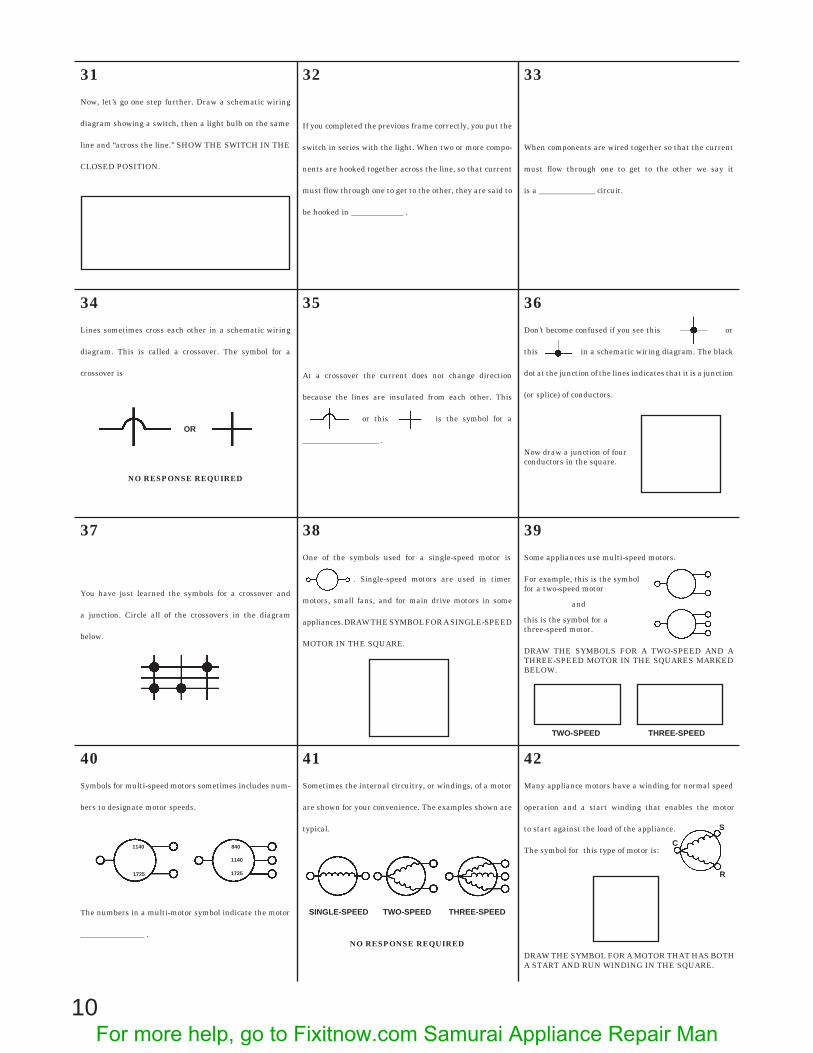
31
Now, let’s go one step further. Draw a schematic wiring
diagram showing a switch, then a light bulb on the same
line and “across the line.” SHOW THE SWITCH IN THE
CLOSED POSITION.
32
If you completed the previous frame correctly, you put the
switch in series with the light. When two or more compo-
nents are hooked together across the line, so that current
must flow through one to get to the other, they are said to
be hooked in _____________ .
33
When components are wired together so that the current
must flow through one to get to the other we say it
is a ______________ circuit.
34
Lines sometimes cross each other in a schematic wiring
diagram. This is called a crossover. The symbol for a
crossover is
NO RESPONSE REQUIRED
35
At a crossover the current does not change direction
because the lines are insulated from each other. This
or this is the symbol for a
___________________ .
36
Don’t become confused if you see this or
this in a schematic wiring diagram. The black
dot at the junction of the lines indicates that it is a junction
(or splice) of conductors.
Now draw a junction of fourconductors in the square.
37
You have just learned the symbols for a crossover and
a junction. Circle all of the crossovers in the diagram
below.
38
One of the symbols used for a single-speed motor is
. Single-speed motors are used in timer
motors, small fans, and for main drive motors in some
appliances. DRAW THE SYMBOL FOR A SINGLE-SPEED
MOTOR IN THE SQUARE.
39
Some appliances use multi-speed motors.
For example, this is the symbolfor a two-speed motor
and
this is the symbol for athree-speed motor.
DRAW THE SYMBOLS FOR A TWO-SPEED AND ATHREE-SPEED MOTOR IN THE SQUARES MARKEDBELOW.
40
Symbols for multi-speed motors sometimes includes num-
bers to designate motor speeds.
The numbers in a multi-motor symbol indicate the motor
________________ .
41
Sometimes the internal circuitry, or windings, of a motor
are shown for your convenience. The examples shown are
typical.
NO RESPONSE REQUIRED
42
Many appliance motors have a winding for normal speed
operation and a start winding that enables the motor
to start against the load of the appliance.
The symbol for this type of motor is:
DRAW THE SYMBOL FOR A MOTOR THAT HAS BOTHA START AND RUN WINDING IN THE SQUARE.
TWO-SPEED THREE-SPEED
OR
TWO-SPEED THREE-SPEEDSINGLE-SPEED
C
S
R
1140
1725
840
1140
1725
For more help, go to Fixitnow.com Samurai Appliance Repair Man

11
43
The letters by the terminals of a motor with a start winding
designate their function. The “C” stands for COMMON,
the “S” stands for the terminal connected to the start
winding, and the “M” stands for the terminal connected to
the main or run winding.
The “S” at the terminal on the motor in this frame means
that it is connected to the _______________ winding.
44
You have already learned the symbol for a light bulb.
DRAW THE SYMBOL FOR A LIGHT BULB IN THE
SQUARE BELOW.
That symbol is for the common incandescent light bulb.
45
Appliances use other types of light too. These are the
A.N.S.I. (American National Standards Institute) sche-
matic symbols for fluorescent, neon, and germicidal lamps.
They are gas filled. A dot in the schematic symbol denotes
that the bulb is filled with gas.
THE SYMBOLS ON THIS PAGE HAVE ONE THING IN
COMMON. EACH HAS A _________TO DENOTE A GAS.
46
Now prove to yourself that you can identify the different
types of A.N.S.I. (American National Standards Institute)
schematic light symbols.
NAME THE LIGHTS IN THE ABOVE BLOCKS.
47
Now you’re really rolling. You know the A.N.S.I. (Ameri-
can National Standards Institute) schematic symbols for:
Four kinds of lights.
Resistors and heaters.
Several kinds of motors.
Current conductors and crossovers.
And you also know that this is the symbol for
a _____________ .
48
Let’s take a look at two new symbols. This is
the symbol for an earth ground, and this is
the symbol for a chassis ground.
DRAW THE SYMBOLS FOR THE TWO TYPES OFGROUNDS IN THE SQUARES.
EARTH GROUND CHASSIS GROUND
49
When a product is properly grounded it protects the user
from electrical shocks if the product malfunctions.
This is the symbol for a ____________ ground.
50
The symbol for a ground can be combined with other
symbols to indicate that the component is grounded. For
example, this combined with this
would be the symbol for a grounded ___________ ______ .
51
Correct! Whenever you see this symbol for
a grounded service cord you know that the product is
_________________ for safety.
52
You know what a bulb and a switch are used for, but what
is the purpose of a ? This is the symbol for
a fuse. A fuse prevents overload of a circuit or component
or power source when something goes wrong. A fuse is used
to prevent ____________________ .
53
In order for a fuse to protect a circuit or component from
overload it must be wired in series with the item it is
protecting. A fuse must be wired in
_____________ to protect a component from overload.
C
S
M or R
(1) (2)
(3) (4)
1 2
3 4
54
In the space below draw a fuse, switch, and a light bulb in
series. Show a grounded service cord in the diagram.
For more help, go to Fixitnow.com Samurai Appliance Repair Man

12
55
Now, let’s take a close look at switches. Up to this point you
have been using a simple on-off (single-pole, single-throw)
switch. Here is the symbol for a single-pole, double-throw
switch:
DRAW THE SYMBOL FOR ASINGLE-POLE, DOUBLE-THROWSWITCH IN THE SQUARE.
56
In the diagram the switch is closed through contact “W”
completing a circuit through the motor.
If the switch were closed through contact “B,” the circuit
would be through the ____________ ___________ .
57
Some appliances use multi-position switches. Here is the
symbol for a typical multi-position switch.
The symbol above is for a ___________ - ______________
58
In the diagram the multi-position switch is closed throughcontact “B” and making a circuit through the heater.
If the switch were closed through contact “A,” the circuit
would be through the ___________ __________ and if the
switch were closed through contact “C,” the circuit would
be through the ______________ .
59
Let’s take a look at pushbutton switches. There are threebasic types of pushbutton switches used in appliances:
The pushbutton switch that is normally open is generallyused on "push-to-start" switches. The pushbutton switchthat is normally closed is used on refrigerator doors. Thetwo-circuit pushbutton switch is sometimes used to startfluorescent lights.
NO RESPONSE REQUIRED
60
Identify the three types of pushbutton switches by placingthe correct letter in the box below the switch symbol.
A. Pushbutton: (N.O.) MOMENTARY CONTACT
B. Pushbutton: NORMALLY CLOSED
C. Pushbutton: TWO-CIRCUIT
61
The switches that you have learned the symbols for have all
been manually operated switches. This means that you
must do something to open or close the switch. This type of
switch is called a _______________ switch.
62
Appliances use switches that are operated (actuated) by
temperature, pressure magnetism, or centrifugal force.
NO RESPONSE REQUIRED
63
This is part of the symbol for a thermostat.
This plus this =Thermostat.
A thermostat may look like this
or like this
DRAW BOTH OF THESE THERMOSTATS BELOW.
64
Let’s tear the word THERMOSTAT apart and see what it
really means. THERMO is from the Greek word therme
denoting heat.
STAT is also from a Greek word states meaning to render
something stationary — to balance.
Combine the two words into one.
THERMOSTAT = A DEVICE TO ________________ THE
HEAT (OR COLD).
65
Bimetal switches such as motor overload protectors, de-
frost bimetals, and limit switches are thermostats in the
strict sense of the word. Now because a bimetal switch is
activated by temperature changes, it is a _______________
in the strict sense of the word.
66
Thermostats, depending on how they are used, can either
open or close on heat rise. This would be the symbol for a
thermostat that opens on heat rise:
This would be the symbol for a thermostat that closes on
heat rise:
NO RESPONSE REQUIRED
PUSHBUTTON PUSHBUTTON PUSHBUTTONTWO-CIRCUIT(NORMALLY CLOSED)
MOMENTARY CONTACT
(NORMALLY OPEN)
switch.
A
B
A
B
C
For more help, go to Fixitnow.com Samurai Appliance Repair Man

13
67
Now, before you forget, draw the symbols for a thermostat
that closes on heat rise and a thermostat that opens on heat
rise in the squares marked below.
68
Some thermostats are adjustable. If a thermostat is adjust
able it will have an arrow drawn at a 45' angle through it
like this:
An arrow drawn through a thermostat means that the
thermostat is __________________ .
69
The refrigeration control thermostat closes on heat rise
and causes the compressor to run to remove heat:
This maintains a temperature balance. A thermostat in
the sense that we use it is an electrical switch that opens
and closes to maintain a temperature ________________ .
70
Most laundry thermostats open on heat rise:
In other words, once a certain temperature is reached, the
thermostat causes the heat source to turn off. When the
temperature falls to a certain point, the thermostat will
turn on the heat source by making a circuit to it. The
thermostat maintains a temperature _______________ by
turning the heat on and off.
71
Now let’s take a look at another type of switch.
This is the symbol fora pressure switch:
The symbol in this frame is the symbol for a _____________switch.
DRAW THE SYMBOL FOR A PRESSURE SWITCH.
72
Typically, pressure switches are used to control the amount
of water entering automatic clothes washers and dish-
washers:
Automatic washers and dishwashers use ______________
switches to control the amount of water entering the
machine.
73
This type of switch is actuated by centrifu-gal
force and is called, very simply, a centrifugal switch.
DRAW THE SYMBOL FOR A CENTRIFUGAL SWITCH.
74
A typical use of the centrifugal switch is in an appliance
that has a motor with a start winding. The centifugal
switch is wired in series with the start winding of the motor
and is normally closed. When the motor starts, it uses both
its start and run windings. As the motor picks up speed
____________________ force causes the switch to open and
allows the motor to run on its run winding.
75
This is the symbol that Whirlpooluses for a humidistat:
Humidistats are used on dehumidifiers and are generally
adjustable. That is why the arrow is drawn through it.
Humidistats are used to sense moisture, so they are
________________ sensitive controls.
76
Now you are really rolling on switches. Sometimes two
switches are linked together mechanically.
To show this, a dotted line is drawnbetween the switch blades:
NOW, YOU CONNECT THE TWO SWITCHES BELOWWITH A MECHANICAL LINKAGE.
77
Switches linked together mechanically are used in situa-
tions where we want to activate two different circuits by
throwing only one switch lever. The dotted line between
the two switches indicates that they are
______________ ____________________ together.
78
Let’s turn our attention to timers. A timer is actually
a motor-driven switch. Inside the timer there are switch
contacts that are opened and closed by cams that are
turned by the motor. The opening and closing of different
contacts in the timer at different times is what controls the
function of the appliance.
A TIMER IS A MOTOR-DRIVEN ______________ .
OPENS ON HEATRISE
CLOSES ON HEATRISE
For more help, go to Fixitnow.com Samurai Appliance Repair Man

14
79
In a wiring diagram the symbol for a single-speed motor is
used to show the timer motor.
The timer motor is always identified as the timer motor so
you will not confuse it with other motors used in the
appliance.
DRAW AND IDENTIFY THE SYMBOL FOR A TIMERMOTOR.
80
The timer switches (contacts) in the wiring diagram are
represented by this symbol:
The timer switches (contacts) are labeled in the wiring
diagram just as they are labeled on the actual timer.
The symbol in this frame is for a ______________
________________ .
81
To help you identify the internal components of the timer,
they are drawn with heavier (thicker) lines than the other
components in the diagram.
The internal parts of a timer are easy to identify because
they are drawn with _______________ ____________ .
82
The master or control switch used on room air conditioners
is represented by this symbol:
The symbol in this frame is for a ________________ or
________________ switch.
83
As a child, you probably wound insulated copper wire
around a nail to make a battery powered electromagnet
which would pick up iron filings.
It is this basic principle that makes possible what is called
solenoid control. A solenoid is a type of electro- ________ .
84
Let’s review our basics now.
This is a symbol for a single-speed motor.
This symbol and sometimes this
one represent a coil. Whenever a coil is
used you will see one of them.
For example, this symbol , can represent
a solenoid ____________ .
85
A solenoid has a coil of copper wire which pulls an iron core
or bar into the center of the coil when energized. Now let’s
make the symbol for a solenoid.
A solenoid is like an electromagnet except that the iron
core is movable and can do mechanical work.
NO RESPONSE REQUIRED
86
Iron cores are used with a coil in many electrical applica-
tions. The iron core is represented like this:
Solenoids and transformers have iron cores. You might see
solenoid symbols that look like this or
this .
DRAW THE IRON CORE SYMBOL OVER THE SOLE-NOID COIL WHICH DOES NOT SHOW IT.
87
To convert this symbol to a transformer
symbol, we simply add a second winding like this:
One winding with straight lines represents a solenoid.
When there are two windings shown, it is always a
____________________ .
88
A transformer may be employed to increase voltage, de-
crease voltage, or isolate a circuit from ground without
affecting its voltage.
DRAW THE SYMBOL FOR A TRANSFORMER.
89
The number of turns in each winding determines the
primary and secondary of a transfomer. The low voltage
will have fewer turns.
To actually determine the primary and secondary wind-
ings you must know whether you are working with a step-
up or step-down transformer. Is this
the symbol for a transformer or solenoid?
90
Probably the most complicated symbol you will find on a
schematic diagram is the relay.
One type of relay is a combination of two items, the
solenoid and a switch.
PUT THEM TOGETHERTHEY LOOK LIKE THIS:
DRAW THE RELAY IN THE BOX.
LO COOL
HI COOL
HI FAN
OFF
TIMER SWITCH REGULAR SWITCH
COIL IRONCORE
SOLENOID
HIGH VOLTAGE
LOW VOLTAGE
For more help, go to Fixitnow.com Samurai Appliance Repair Man

15
91
Relays are of several types. One popular type used to startrefrigerator motors is the magnetic relay:
In the magnetic type the circuit is closed to the startwinding for a very brief period because the greater currentrequired to start the motor compressor induces sufficientmagnetism to hold the switch from “L” to “S” closed. Whenthe motor reaches operating speed it draws less current,the _______________ weakens and the switch drops open.
92
A magnetic relay relies on the heavier current draw of
a motor during start to energize the solenoid and close the
switch which will send current to the start winding. As
soon as this motor is almost up to speed, the current draw
is reduced and the solenoid can no longer hold the starting
switch closed. What two basic symbols compose a magnetic
relay?
_________________ and __________________ .
93
You have already been told this fact. Let us see if you
remember. When components are wired together so that
current must flow through the one to get to the other we say
it is a ______________ circuit.
94
Some electric motors used to drive refrigerator compres-sors require extra power at the instant of start. To providethis momentary voltage boost, a starting capacitor may beused.
The symbol for a capacitor is . The startingcapacitor is always located in the line from the startterminal on the relay to the start winding of the motor. Puta starting capacitor in this circuit. The letter “S” identifiesthe start winding. The run winding is marked “R” or “M.”
NO RESPONSE REQUIRED
95
A relay completes the circuit to the start winding at
the instant of start. If a starting capacitor is used, it will be
energized when the ____________ closes the circuit to the
start winding.
96
A start capacitor is in _______________ with the start
winding.
97
Another type of relay is the current or hot wire relay. Thehot wire relay uses a short piece of iron wire to conductcurrent from the line to both the main and start windings.The resistance to the current flow afforded by the iron wirecauses it to heat and stretch. As it stretches, it permits thestart winding (which draws the most current) to open.
An excessive overload due to low line voltage or a defectivemotor will heat the wire more and the run winding contactswill also ____________ .
98
In identifying the markings on this hot wire relay, look for
an “S” which means start winding and either “R” for
running winding or “M” for main motor winding. The side
of the line entering the relay will probably be marked “L”
or “L1.”
WHAT IS THE UNMARKED TERMINAL?
99
Bells and buzzers are used to notify the user that theappliance has completed a specific function. The symbolsfor a bell and a buzzer are below.
DRAW THE SYMBOLS FOR A BELL AND A BUZZERBELOW.
BELL BUZZER
BELL BUZZER
100
Buzzers are sometimes adjustable. Remember the 45°
arrow that was drawn through the symbol for a thermostat
to denote that it was adjustable? That 45° arrow drawn
through the buzzer denotes that it is adjustable.
DRAW THE SYMBOL FOR AN ADJUSTABLE BUZZERBELOW.
101
Being able to read a schematic may be a great help introuble diagnosis. From schematics we can determinewhere to expect to find voltage present and where to findcontinuity. What is continuity?
YOUR OWN WORDS
102
Continuity might be one way of saying connected. Things
which are connected across the line have ______________ .
On an ohmmeter, components which have continuity will
give a reading on the scale. The extent of meter needle
deflection will depend on the resistance of the circuit
or component being checked. If more than one range
of resistance scales is available, the high range scale will
give the most needle deflection for checking components
for continuity.
INCOMINGCURRENT
TO START WINDINGTO MAIN WINDING
For more help, go to Fixitnow.com Samurai Appliance Repair Man

16
103
Another clue to the meaning of continuity is the similar
word “continuous.” Things or circuits which have continu-
ity have no breaks or open spots. They are continuous. In
electrical “talk” things which have continuity will conduct
_____________________ .
104
Continuity does not mean that there will be no resistanceto the circuit. It simply means that there will be no opendrawbridges (switches) or bridges out (broken wires, etc.)in the road the current is traveling. There may be detours(resistors, motor, lights) but the journey may be completedfrom one side to the other. Wire “N” below has continuity,wire “B” does not.
The circuit shown below has ______________________ .
105
If something electrical is to operate (that is run, heat,vibrate, etc.), current must flow. In order for current toflow, a circuit must be complete. We say a complete circuithas continuity because it is continuous from one side of theline to the other with no breaks. Does this circuit havecontinuity from one side of the line to the other?
Yes No
106
Here is a wiring diagram in which we show the names of the
components, but we did not draw in the symbols.
WE WANT YOU TO DRAW IN THE SYMBOLS BELOW.
107
You might have shown the light switch open or closed in thelast frame, and in either case you were right.
Now we want you to draw a wavy line through the currentcarrying (energized) circuits in this diagram. We will helpyou get started, but want you to continue the wavy linesthrough energized circuits.
108
Even if you do not recognize all A.N.S.I. (American Nat-
ional Standards Institute) symbols, you can learn to read
a wiring diagram. Most wiring diagrams show the name of
the component along with its Basic Symbol. Some slight
deviation in symbols will not be a problem to you, once you
know the B_________ S______________ .
109
Let’s suppose that the appliance is plugged into a wall
receptacle. TRACE OUT THE ENERGIZED CIRCUITS
SHOWN ON THIS PARTIAL DIAGRAM. (Use a wavy
line.)
110
Many symbols in this wiring diagram
do not conform to A.N.S.I. standards,
but we want to prove to you that you can
read any wiring diagram, if you know
the basic principles.
NAME TWO HEATERS WHICH ARENOT SHOWN ENERGIZED IN THISSCHMATIC.
1. ___________________
2. ___________________
111
The one thing to remember about the schematic of a
grounded plug on a wiring diagram, you are looking into
the plug end.
NO RESPONSE REQUIRED
A B
POWER CORD
NEUTRAL SIDE(W)
HOT SIDE(BK)
GROUND
WALL OUTLET
WIRING DIAGRAM
STILE HEATER
CONDENSER FANTIMERTHERMOSTAT
RELAYM
S
C
COMPRESSOROVERLOAD
DEFROST HEATER
LIGHT SWITCH
DRAIN HEATER
SIGNAL LIGHT
CABINET LIGHT
DOOR HEATER
LIMIT SWITCH
EVAPORATOR FAN
For more help, go to Fixitnow.com Samurai Appliance Repair Man

17
1. Wiring
2. Symbol
3. Symbols
4. Symbols
5. Diagrams
6. Pictures
7. Pictorial
8. Pictorial Wiring Diagram
9. Pictorial
10.
11. Schematic
12. Schematic
13.
14.
15. Closed
16.
17. Resistor
18. Current
19. Resistor
20. No Response Required
21.
22. Schematic
23. Straight
24. Current
25. No Response Required
26. Line
27. Yes
28. Line
29. Parallel
30.
ANSWERS TO QUESTIONS FROM PAGES 7-16
31.
32. Series
33. Series
34. No Response Required
35. Crossover
36.
37.
38.
39.
40. Speeds
A
WALL PLUG
SCHEMATIC
LIGHT SWITCH
HEATER
LIGHT
MOTOR
MOTOR
INCANDESCENTLIGHT
TWO-SPEED
THREE-SPEED
For more help, go to Fixitnow.com Samurai Appliance Repair Man
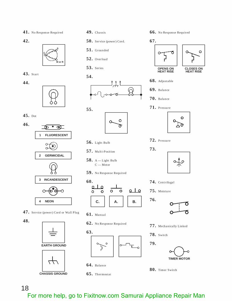
41. No Response Required
42.
43. Start
44.
45. Dot
46.
47. Service (power) Cord or Wall Plug
48.
49. Chassis
50. Service (power) Cord.
51. Grounded
52. Overload
53. Series
54.
55.
56. Light Bulb
57. Multi-Position
58. A — Light BulbC — Motor
59. No Response Required
60.
61. Manual
62. No Response Required
63.
64. Balance
65. Thermostat
66. No Response Required
67.
68. Adjustable
69. Balance
70. Balance
71. Pressure
72. Pressure
73.
74. Centrifugal
75. Moisture
76.
77. Mechanically Linked
78. Switch
79.
80. Timer Switch
C
S
M or R
EARTH GROUND
CHASSIS GROUND
1 FLUORESCENT
2 GERMICIDAL
3 INCANDESCENT
4 NEON C. A. B.
OPENS ONHEAT RISE
CLOSES ONHEAT RISE
TIMER MOTOR
18For more help, go to Fixitnow.com Samurai Appliance Repair Man
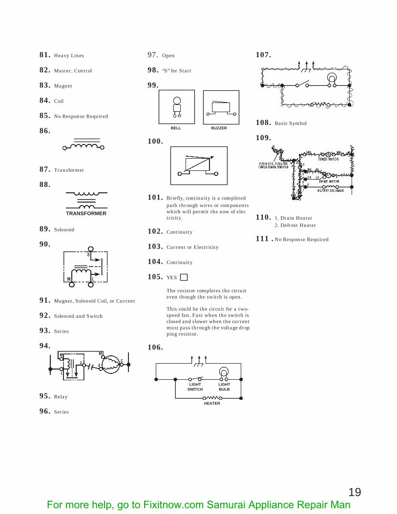
81. Heavy Lines
82. Master, Control
83. Magnet
84. Coil
85. No Response Required
86.
87. Transformer
88.
89. Solenoid
90.
91. Magnet, Solenoid Coil, or Current
92. Solenoid and Switch
93. Series
94.
95. Relay
96. Series
97. Open
98. “S” for Start
99.
100.
101. Briefly, continuity is a completedpath through wires or componentswhich will permit the now of electricity.
102. Continuity
103. Current or Electricity
104. Continuity
105. YES
The resistor completes the circuiteven though the switch is open.
This could be the circuit for a two-speed fan. Fast when the switch isclosed and slower when the currentmust pass through the voltage dropping resistor.
106.
107.
108. Basic Symbol
109.
110. 1. Drain Heater2. Defrost Heater
111 . No Response Required
TRANSFORMER
BELL BUZZER
LIGHTSWITCH
LIGHTBULB
HEATER
19For more help, go to Fixitnow.com Samurai Appliance Repair Man

20
NOTES
For more help, go to Fixitnow.com Samurai Appliance Repair Man

BLANK
For more help, go to Fixitnow.com Samurai Appliance Repair Man
BLANK
For more help, go to Fixitnow.com Samurai Appliance Repair Man