Embed Size (px)
Citation preview

Chapter 1
Basic concepts & Laws
2.1 Basic concept of charge, current, voltage, resistance,inductance, Capacitance, power, energy and theirunits.2.2 Basic concept about supply source- D.C. & A.C. (names only)3.1 Statement & explanation of (a) Ohm’s law, resistances in series and parallel (b) Kirchhoff’s Current& Voltage laws3.2 Simple problems on D.C. Circuits
Learning outcomes:
On completion of this chapter, learners should be able to
• classify materials on the basis of electrical conductivity.• define different terminologies often used in Electrical Engineering.• state and explain Ohm’s law.• define resistance and conductance.• calculate equivalent resistance when resistances are connected in series or parallel.• convert star connection to delta or delta connection to star.• define ideal and practical inductance and quality factor.• calculate equivalent inductance when inductances (not mutually coupled) are connected in series or par-
allel.• define ideal and practical capacitance and quality factor.• calculate equivalent capacitance when capacitances are connected in series or parallel.• state and explain Kirchhoff’s laws and solve network problems using these laws.• define and classify energy sources.• convert a voltage source to a current source and vice versa.
1.1 Classification of materials
On the basis of electrical conductivity, materials may be classified into following categories.
Conductors: Materials like copper, aluminum etc. valence band and conduction band are overlapped. Evena little potential difference may cause a large flow of current (caused by the movement of electrons). Thesematerials are called conductors.
Insulators: In materials like wood, mica etc. there is a very large forbidden energy gap (nearly 15eV) betweenvalence band and conduction band. Hence, electrons cannot be easily detached from the atoms unless a veryhigh electric field is applied. Under normal conditions they do not allow any passage of current. These materialsare called insulators.
Semiconductors: In materials like germalium, silicon etc. forbidden gap between valence band and conduc-tion band is small (1eV). Even under room temperature some electrons are available in conduction band to takepart in the flow of current. If temperature is increased more electrons are available. Even though they behavelike insulators at a lower temperature, they behave like a conductor at higher temperature. Their conductivitylies between insulators and conductors. That is why they are called semiconductors.
1
Mr. Arup Kumar Majee,PrincipalJnan Chandra Ghosh Polytechnic

2 CHAPTER 1. BASIC CONCEPTS & LAWS
1.2 Terminologies used
Charge: It is the attribute of matter which is responsible for a force of interaction between two matters undercertain conditions. It is considered as the quantity of electricity. Charge is measured in coulomb. It is definedas an amount of charge possessed by 6.242× 10¹⁸ electrons.
Electric Current: An electric current is caused by the movement of electric charge around a closed path. Itis defined as the rate of flow of positive charge.
i =dq
dt
Unit of Current, Ampere: Current is measured in amperes. One Ampere current means flow of 1Ccharge passing any point of conductor in 1sec.The ampere may also be defined as the current which when flowing through two infinitely long conductors havingnegligibly small cross-sectional area, situated 1 metre apart in the vacuum, produces a force of 2×10⁻⁷N/metrebetween the conductors.
Example 1.1 If 6 coulomb charge passes through copper conductor in 1 minute, what is the value of current?
Solution Given values
Q = 6 coulomb
t = 1min = 60sec
∴ I =Q
t=
6
60= 0.1A
Current flowing through the condutor is 0.1A.
Electric current density: It is defined as the current per unit area of the conducting medium. Consideringuniform current distribution
J =I
A
where A is the cross-sectional area of the conductor. J is measured in ampere per square metre.
Electric Potential: The electric potential V of a point A with respect to another point B is the work doneagainst the field in taking a positive charge from point B to point A.
v =dW
dq
Electromotive force: It is the voltage provided by an energy source which forces a current to flow in a closedcircuit.
Voltage drop: Voltage drop between two points is defined as the decrease in electric potential energy intransferring a unit positive charge from one point to the other.
Unit of voltage, Volt: E.m.f, potential, voltage drop all are measured by volts. One volt is the measureof voltage between two points when 1J of energy is required to transfer 1 coulomb of charge from one point toanother.
Power: It is defined as the rate at which the work is being done in an electric circuit. It may also be definedas the rate at which energy is being consumed in an electric circuit.
If in time ∆t, a small charge ∆q is moved through an element having a voltage v across it,
P = limt→0
∆W
∆t=dw
dt= v
dq
dt= vi
Electric power is measured in Watts.

1.3. ELECTRICAL CIRCUIT ELEMENTS 3
Electric energy: The energy which is caused by the movement of electrons from one place to another iscalled electric energy. It is measured in Joules.
If in time ∆t, a small charge ∆q flows through an element having a voltage v across it,
W =
∫dw =
∫vdq =
∫vidt =
∫pdt
Electric energy may be defined as total power consumed over a specific time. It can be measured in Watt-sec(practical unit used: kilowatt-hours).
Electrical Networks and circuits: Any combination of electrical elements is known as a network . Anetwork may contain active elements or not. But circuit is a closed energized network. A circuit must containan active element.
Therefore, all circuits are networks but all networks are not circuits.
Nodes and branches A node is a point where two or more circuit elements join. If three or more elementsare joined at a node the node is called an essential node.
A branch is a path which connects two nodes.
Loops and meshes: A loop or mesh is a closed path obtained by starting at a node and returning at thesame node through a set of connected circuit elements without passing any intermediate node more than once.
A mesh is the smallest loop. it does not contain any other loop.
Therefore, all meshes are loops but all loops are not meshes.
Circuit element: A circuit element is any two terminal component which constitutes a circuit. Energysources, diodes, resistors, inductors etc. are circuit elements.
Active element and passive elements: An active element can generate electric energy. Any voltage sourceor current source is an active element.
A passive element cannot generate electric energy but it can either consume or store it. Resistors, inductorsand capacitors are commonly used passive elements. A resistor dissipates energy whereas an inductor storesenergy in magnetic field and a capacitor stores energy in electrostatic field.
Bilateral and unilateral elements: For a bilateral element , the same relationship between current andvolatge exists for either direction of current flow. Resistors, inductors are bilateral elements.
On the other hand, different current voltage relationships obtained for both direction of current flow forunilateral elements. Diodes, transistors etc. are unilateral elements.
1.3 Electrical Circuit Elements
There are four basic circuit elements: resistors, inductors, capacitors and energy sources.
1.3.1 Resistor
Ohm’s law
Statement: Physical conditions (tempertaure, material etc.) remaining constant, current (I) through anyconductor is directly proportional to the potential difference (V ) between its ends.
I ∝ V
Or, I = G.V where proportionality constant, G is the conductance measured in mho.Or, V = R.I where proportionality constant, R = 1/G is the resistance measured in Ohm.
In other words, Ohm’s law may be stated as: potential difference between the two ends of a conductor isdirectly proportional to the current flowing through it provided physical conditions remain constant.
Example 1.2 The potential drop across 15Ω resistor is 60V. What will be the value of current flowing throughit?

4 CHAPTER 1. BASIC CONCEPTS & LAWS
Figure 1.1: Symbol of a resistor Figure 1.2: Voltage-ampere characteristics of a linear resistor
Solution Given values
Resistance, R = 15Ω
Potential drop, V = 60V
∴Current flowing through the resistor, I =V
R=
60
15= 4A
Resistance, R Resistance is the property of a material which resists the flow of current through it. It ismeasured in Ohms (Ω).
R =V
I
A conductor has a resistance of 1Ω while carrying 1A current it produces a voltage drop of 1V across it.
Resistor: A two terminal electrical device (shown in Figure 1.1) which has resistance as its dominant char-acteristic is called a resistor. It is a circuit element which consumes power and dissipates energy as heat whilecarrying current. A resistor which follows Ohm’s law is called a linear resistor and which does not follow Ohm’slaw is called a non-linear resistor.
Power consumed by a resistor having resistance R Ω, carrying a direct current, I
P = V I = I2R =V 2
R(in watts)
Energy dissipated in a resistor over a time duration T sec,
Wd = PT = V IT = I2RT (in joules)
While carrying an alternating current, i instantaneous power absorbed by a resistor p = vi and energy dissipated
Wd =
∫ T
0
vidt =
∫ T
0
Ri.idt =
∫ T
0
i2Rdt = I2rmsRT
where, Irms is the root mean square value of an alternating current.
Example 1.3 What is the value of current flowing through a 1500W electric iron when connected to a 230V,50 Hz ac source ?
Solution Given values
Power rating of heater, P = 1500W
Supply voltage, V = 230V
Current flowing through the heater, I =P
V=
1500
230= 6.5217A
DC resistance of a conductor : While direct current flows through a conductor, current flows uniformlythrough the conductor. Resistance may be expressed as
R = ρl
A
where l is the length of a conductor measured in metres.A is the cross-sectional area of a conductor measured in square metres.ρ is the resistivity of the conductor material measured in ohm-metre.

1.3. ELECTRICAL CIRCUIT ELEMENTS 5
Resistivity: Resistivity is the ability of a material to oppose the flow of current.
[ρ] =[R][A]
[L]=
Ω×m2
m= Ω−m
Resistivity is measured in Ω−m
Conductance: Conductance, G is the reciprocal of resistance. It is measured in mho (f) or siemens (S).
G =1
R= σ
A
l
where σ is the conductivity of the conductor material measured in mho per metre.
Conductivity Conductivity is the ability of the material to facilitate the flow of current.
[σ] =[G][L]
[A]=
f×mm2
= f/m
Conductivity is measured in f/m
AC Resistance of a conductor: While alternating current flows through a conductor, current cannot flowuniformly through the conductor. Due to reactive effect current shows a tendency to flow through the surfaceof the conductor which is known as skin effect . Effective cross sectional area of conductor reduces due to this,thus increasing the resistance.
Usually ac resistance is considered 1.2 to 1.3 times the dc resistance of a conductor.
Example 1.4 The resistance of a heating element made of nichrome wire is 25Ω. The diameter of the wire is0.235 mm and the resistivity is 1.2µΩ−m. What is the length of the wire used?
Solution Let R be the resistance of the nichrome wire having resistivity, length and cross-sectionalarea ρ, l and A respectively.
Given values
ρ = 1.2 µΩ−md = 0.235 mm = 0.235× 10⁻³ m
A = πd2
4= π
(0.235× 10⁻³
)24
m2
l =R.A
ρ=
25× π (0.235×10⁻³)2
4
1.2× 10−6= 0.9036 m
Example 1.5 In the manufacturing process of a copper wire, a thick circular rod which has a resistance of0.01Ω, is drawn out without a change in volume until its diameter is one-tenth of what it was. What is the newresistance?
Solution Let R1 be the resistance of the copper rod having volume, length and cross-sectionalarea V1, l1 and A1 respectively.
Let R2 be the resistance of the copper wire having volume, length and cross-sectional area V2, l2and A2 respectively.
d2 =d1
10V1 = V2
Or, l1A1 = l2A2
Or,l1l2
=A2
A1=
(d2
d1
)2
=1
100
R1 = ρl1A1
R2 = ρl2A2
∴R1
R2=
l1l2× A2
A1=
1
10000R2 = 10000× 0.01 = 100 Ω

6 CHAPTER 1. BASIC CONCEPTS & LAWS
Example 1.6 The A current of 2.5A flows in a coil of copper wire having cross sectional area of 0.17mm2 whenconnected to a 50V dc supply. Find the length of the wire on the coil if the resistivity of copper is 17µΩ−mm.
Solution Let R be the resistance of the copper wire having resistivity, length and cross-sectionalarea ρ, l and A respectively.
Given values
V = 50 volt
I = 2.5 A
ρ = 17 µΩ−mm = 17× 10−6 × 10−3 Ω−m
R =V
I=
50
2.5= 20 Ω
l =R.A
ρ=
20× 0.17× 10−6
17× 10−6 × 10−3= 200 m
1.3.2 Inductor
Inductance, L When an electric current flows through a circuit it produces a flux around it. Inductance orself inductance is defined as the ratio of change in magnetic flux linkage to the change in current.
L = Ndφ
di
It is measured in henry (H). 1H=1wb/A
(a) air-core (b) iron-core
Figure 1.3: Symbol of an inductor
Inductance may be defined as the attribute of an electrical device which opposes instantaneous change incurrent. This may be compared with the property of inertia.
In direct current circuits, its effect is felt during switching on or switching off. As there is no change in fluxduring steady state, it acts like a short circuit. But in alternating current circuits, its presence is always there.
Inductor: It is a two terminal electrical device which can store energy in magnetic field . It is usually madeby winding a coil (shown in Figure 1.3) on a magnetic core (for smaller values, air-core is used). For largercurrents core becomes saturated and inductor value reduces, thus non-linearity is introduced.
Energy stored : Ws =
∫vidt =
∫Ldi
dtidt =
∫Lidi =
1
2Li2
Example 1.7 What will be the induced emf in a coil if current flowing through it reduces from 10A to 5A in0.1sec? Assume self inductance of the coil is 5H.
Solution Induced emf,
e = −Ldidt
= −LI2 − I1dt
= −5× (5− 10)
0.1= 250V
Example 1.8 How much energy is stored in an inductor of 40 mH when a current of 4 A is passing throughit?
Solution Energy stored,
E =1
2Li2 =
1
2× 40× 10−3 × 42 = 0.32J

1.4. CONNECTION OF CIRCUIT ELEMENTS 7
i =dq
dt= C
dvcdt
Or, vc =1
C
∫idt
Figure 1.4: Symbol of a capacitor
1.3.3 Capacitor
Capacitance is the measure of change in electric charge stored for a certain change in potential.
C =dq
dvc
Capacitance is measured in Farad (F). 1 Farad=1 coulomb per volt.Capacitance may be defined as the attribute of an electrical device which opposes instantaneous change in
voltage across it. In direct current circuits, its effect is felt during switching on or switching off. As there isno change in charge during steady state, it acts like an open circuit. But in alternating current circuits, itspresence is always there.
Capacitor: It is a two terminal electrical device (shown in Figure 1.4) which can store energy in electrostaticfield. It is made of two metal plates separated by some dielectric.
C = εA
d= ε0εr
A
d
where C is the capacitance in Faradε is the absolute permittivity of insulatorεo is the permittivity of vacuumεr is the relative permittivity of insulatorA is the area of each plate in sq, metred is the separation between the plates in metre.
Example 1.9 A capacitor comprises of two square metal plates each of side 120mm separated by a dielectricof thickness 2mm and permittivity 5. Determine the value of the capacitance.
Solution
C =εoεA
d=
1
36π × 109× 5× 1202 × 10−6
2× 10−3= 318.31pF
Example 1.10 The dielectric thickness between the plates of a capacitor is 2mm and its relative permittivityis 5. The area of the plates is 50 square millimeters. The dielectric medium has electric field strength of 400Vper mm. Find (a) capacitance; (ii) total charge on each plate.
Solution
C =εoεA
d=
1
36π × 109× 5× 502 × 10−6
2× 10−3= 1.1052µF
V = 400× 2 = 800V
Q = CV = 1.1052× 10−6 × 800 = 884.19µC
1.4 Connection of Circuit Elements
Circuit elements are connected in various ways to form networks. Commonly used connections are: series,parallel, star and delta.
1.4.1 Series Connection of Resistors
Resistors are said to be connected in series when same current flows through them. Figure 1.5a shows threeresistors R1, R2 and R3 connected in series. Potential drops are V1, V2 and V3 across the each resistor respec-tively. Supply voltage V must be equal to the sum of these three voltage drops. Figure 1.5b shows a resistorReq which draws the same current when connected to the same source.
Applying Kirchhoff’s voltage law:
V = V1 + V2 + V3
Or, IReq = IR1 + IR2 + IR3
Or, Req = R1 +R2 +R3

8 CHAPTER 1. BASIC CONCEPTS & LAWS
(a) Series Connection (b) Equivalent
Figure 1.5: Series connection of resistor
Properties of series circuits
1. Same current passes through all the resistors.2. Summation of voltage drops across the series connected resistors equals to the supply voltage, V i.e.V =V1 + V2 + . . .+ Vn =
∑nVi.
3. Equivalent resistance of the whole combination is equal to the sum of individual resistances i.e.Req =R1 +R2 + . . .+Rn =
∑nRi.
4. Maximum voltage drop takes place across the resistor having maximum resistance.5. If R1 = R2 = . . . = Rn = R then Req = nR.
Voltage divider relationships
V1 = IR1 =R1
ReqV =
R1
R1 +R2 +R3V
V2 = IR2 =R2
ReqV =
R2
R1 +R2 +R3V
V3 = IR3 =R3
ReqV =
R3
R1 +R2 +R3V
These relationships are helpful to find the potential drop across a particular component when the supply voltageis given.If R1 = R2 = R3 = R, then V1 = V2 = V3 = V
3 .
In general, if R1 = R2 = . . . = Rn = R, then V1 = V2 = . . . = Vn = Vn .
Example 1.11 Three resistors 2Ω, 3Ω and 5Ω are connected in series across a 20V supply system. What willbe the voltage across each resistor?
Solution Current flowing through the circuit
I =20
2 + 3 + 5= 2A
Voltage across 2Ω resistor V1 = IR1 = 2× 2 = 4 volts
Voltage across 3Ω resistor V2 = IR2 = 2× 3 = 6 volts
Voltage across 5Ω resistor V3 = IR3 = 2× 5 = 10 volts
Example 1.12 Three resistors 3Ω, 6Ω and 9Ω are connected in series across a 90V supply system. What willbe the power absorbed by 3Ω resistor?
Solution Current flowing through the circuit
I =90
3 + 6 + 9= 5A
Power absorbed by 3Ω resistorP = I2R = 52 × 3 = 75W
Example 1.13 The element of a 500W electric press is designed for use on 200V, 50Hz supply. What valueof resistance is needed to be connected in series in order that the press can be operated at 230V ac supply.
[Punjab Technical University,Basic Electrical and Electronics Engineering, December, 2004]
Solution Rated current of the press I = PV = 500
200 = 2.5A
Extra voltage applied VR = 230− 200 = 30V must be dropped across the external resistance.
External resistance to be connected in series Rext = VR
I = 302.5 = 12Ω

1.4. CONNECTION OF CIRCUIT ELEMENTS 9
Example 1.14 A 100V, 60W bulb is to be operated from 220V supply. What resistance must be connected inseries with the bulb to glow normally?
Solution Rated current of the bulb I = PV = 60
100 = 0.6A
Extra voltage applied VR = 220− 100 = 120V must be dropped across the external resistance.
External resistance to be connected in series Rext = VR
I = 1200.6 = 200Ω
1.4.2 Parallel Connection of Resistors
Resistors are said to be connected in parallel when they are connected between the same two points i.e. thesame voltage drop appears across them. Current drawn by the combination must be the sum of the currentsdrawn by the each resistor. Figure 1.6a shows three resistors R1, R2 and R3 connected in parallel. Currentdrawn by them are I1, I2 and I3 respectively. Applying Kirchhoff’s current law:
I = I1 + I2 + I3
Or,V
Req=
V
R1+
V
R2+
V
R3
Or,1
Req=
1
R1+
1
R2+
1
R3
Or, we can write,
I = I1 + I2 + I3
Or, V Geq = V G1 + V G2 + V G3
Or, Geq = G1 +G2 +G3 =1
Req
(a) Parallel con-nection
(b) Equivalent
Figure 1.6: Parallel connection of resistor
Properties of parallel circuits
1. Voltage across all the resistors is same.2. Summation of current passing through the parallel connected resistors equals to the supply current, I
i.e.I = I1 + I2 + . . .+ In =∑n
Ii.3. Equivalent conductance of the whole combination is equal to the sum of individual conductances i.e.Geq =G1 +G2 + . . .+Gn =
∑nGi.
4. Maximum current passing through the resistor having maximum conductance or least resistance.5. If G1 = G2 = . . . = Gn = G then Geq = nG i.e. Req = 1/Geq = R/n
Current divider relationships
I1 = V G1 =G1
GeqI =
G1
G1 +G2 +G3I
I2 = V G2 =G2
GeqI =
G2
G1 +G2 +G3I
I3 = V G3 =G3
GeqI =
G3
G1 +G2 +G3I

10 CHAPTER 1. BASIC CONCEPTS & LAWS
These relationships are helpful to find the current through a particular branch when the supply current isknown.If R1 = R2 = R3 = R, then G1 = G2 = G3 = G. We get I1 = I2 = I3 = I
3
In general, if R1 = R2 = . . . = Rn = R, then G1 = G2 = . . . = Gn = G. We get I1 = I2 = . . . = In = In
Example 1.15 Find equivalent resistance between A and B in the network shown in Figure 1.8a.
(a) (b)
Figure 1.7: Circuit diagrams of Example 1.15
Solution From Figure ??
RAB = 10||10 =10× 10
10 + 10= 5Ω
Example 1.16 Find equivalent resistance between A and B in the network shown in Figure ??.
(a) (b)
Figure 1.8: Circuit diagrams of Example 1.16
Solution
RAB = 12||40||60 = 12||40× 60
40 + 60= 12||24 =
12× 24
12 + 24= 8Ω
Example 1.17 Two resistors are connected in parallel across a 200V dc supply. The total current taken is 20A and power dissipated in one of the resistors is 2000W. What is the resistance of each element?
Solution
R1 =V 2
P=
2002
2000= 20Ω
Req =V
I=
200
20= 10Ω
10 =R1R2
R1 +R2=
20R2
20 +R2
R2 = 20Ω
Example 1.18 Two coils are connected in parallel across a 120V dc supply, take 10 A from the supply. Powerdissipated in one coil is 400W. What is the resistance of each coil?
Solution
R1 =V 2
P=
1202
400= 36Ω
Req =V
I=
120
10= 12Ω
12 =R1R2
R1 +R2=
36R2
36 +R2
R2 = 18Ω

1.4. CONNECTION OF CIRCUIT ELEMENTS 11
Example 1.19 For the circuit shown in Figure 1.9 find the total resistance and battery current.
Figure 1.9: Circuit diagram for Example 1.19
(a) (b) (c)
Figure 1.10: Circuit diagram for Example 1.19
Solution Resistances 3Ω and 2Ω are connected in series. By adding them we get circuit shownin Figure 1.10a. Now, two 5Ω resistances are in parallel. Their equivalent resistance will be 2.5Ωshown in Figure 1.10b. Now, two 2.5Ω resistances are in series. The circuit reduces to Figure 1.10c.
Req = 10||5 =10× 5
10 + 5=
10
3= 3.33Ω
Battery current = 20×310 = 6A
Example 1.20 For the circuit shown in Figure 1.11 find the value of R for which the total current taken is9A. Determine the branch currents I1 and I2.
Figure 1.11: Circuit diagram for Example 1.20
Solution
Req =40
9Ω
Req = (2 + 8)||(5 +R) =10× (5 +R)
15 +RΩ
Or, R = 3Ω
I1 =5 + 3
5 + 3 + 2 + 8× 9 =
8
18× 9 = 4A
I2 = 9− 4 = 5A
1.4.3 Series-Parallel connection
In some complex circuits both series and parallel connections are present as shown in Figure 1.12.

12 CHAPTER 1. BASIC CONCEPTS & LAWS
(a) Series-Parallel connection (b) Simplied series con-nection
(c) Equivalent
Figure 1.12: Series-Parallel connected Resistors and their equivalent resistor
Steps:
1. Determine equivalent resistance of the series connected part (Req1 = R1 +R2).
2. Determine equivalent resistance of the parallel connected part ( 1Req2
= 1R1
+ 1R2
).
3. Now add up them to get total equivalent resistance (Req = Req1 +Req2).
Example 1.21 A resistance of 10Ω is connected in series with two resistances each of 15Ω in parallel. Whatresistance must be shunted across this branch so that the total current taken shall be 1.5A when connected acrossa 20V dc supply?
Solution
Req1 = 10 + 15||15 = 10 +15
2=
35
2Ω
Req =20
1.5=
40
3Ω
Req =Req1 ×RSh
Req1 +RSh
Or,40
3=
352 ×RSh
352 +RSh
Or, RSh = 56Ω
Example 1.22 In the circuit shown in Figure 1.13a, calculate the power dissipated in each resistor and thereading of a voltmeter connected across 7Ω resistor.
(a) (b)
Figure 1.13: Circuit diagrams for Example 1.22
Solution
Req = 7 +12× 24
12 + 24= 15Ω
I =180
15= 12A
I1 =24
12 + 24× 12 = 8A
I2 = 12− 8 = 4A

1.4. CONNECTION OF CIRCUIT ELEMENTS 13
Power dissipated in 7Ω resistor, P7Ω = 122 × 7 = 1008W
Power dissipated in 12Ω resistor, P12Ω = 82 × 12 = 768W
Power dissipated in 24Ω resistor, P24Ω = 42 × 24 = 384W
Voltmeter reading connected across 7 Ω resistor, V7Ω = 12× 7 = 84V
Example 1.23 If 9 V is applied across A and B (Figure 1.14), calculate the total current and the value of aseries resistance to halve the total current.
Figure 1.14: Circuit diagram for Example 1.23
Solution
Y1 =1
2+
1
4+
1
6+
1
8= 1.0417f
R1 = 0.96Ω
R2 =3× 6
3 + 6= 2Ω
Req =3× 2.96
3 + 2.96= 1.4899Ω
I =9
1.4899= 6.0407A
Value of a series resistance to halve the total current
Rext = Req = 1.4899Ω
Example 1.24 Twelve identical wires, each of resistance R are connected to form a cube as shown in Figure1.15. If a current of 10A enters into the cube at the corner A and leaves it diagonally from the opposite cornerG. What will be the potential difference between these two corners for R = 6Ω?
Figure 1.15: Circuit diagram for Example 1.24
Solution As all the resistances are identical, current entering the corner A will be equally dividedinto three sides AB, AD, AE. Hence, B,D and E are at equal potential. Similarly currents enteringthe node G are equal and C,F,H are at equal potential. At point B current in branch AB dividesequally to flow into BC and BF, at D the branch current of AD divides equally to flow into DHand DC and at E the branch current of AE divides equally to flow into EH and EF. The equivalentcircuit of this cube is shown in Figure 1.16.

14 CHAPTER 1. BASIC CONCEPTS & LAWS
Figure 1.16: Circuit diagram for Example 1.24
RAD = RCG =R
3
RDC =R
6
Req = RAD +RDC +RCG =R
3+R
6+R
3=
5R
6= 5Ω
VAG = 10× 5 = 50V olts
Example 1.25 Find equivalent resistance between A and B in the network shown in Figure 1.17a.
(a) (b)
(c) (d)
Figure 1.17: Circuit diagrams of Example 1.25
Solution We know,
(3 + 3)||6 =6× 6
6 + 6= 3Ω
RAB = 3||(3 + 3) =3× 6
3 + 6= 2Ω
Example 1.26 Find equivalent resistance between A and B in the network shown in Figure 1.18a.
Solution From Figure 1.18b
RAB = (10 + 10)||(10 + 10) = 20||20 =20× 20
10 + 20= 10Ω
Example 1.27 Find equivalent resistance between A and B in the network shown in Figure 1.19a.

1.4. CONNECTION OF CIRCUIT ELEMENTS 15
(a) (b)
Figure 1.18: Circuit diagrams of Example 1.26
(a) (b)
Figure 1.19: Circuit diagrams of Example 1.27
Solution From Figure 1.19b
RAB = (7||7) + (7||7) = 3.5 + 3.5 = 7Ω
Example 1.28 Find equivalent resistance between A and B in the network shown in Figure 1.20a.
(a) (b) (c)
Figure 1.20: Circuit diagrams of Example 1.28
Solution
(4 + 4 + 4)||6 =12× 6
12 + 6=
72
18= 4Ω
From Figure 1.20c
RAB = 4 + 4 = 8Ω
1.4.4 Star and Delta Connection of Resistors
Apart from series and parallel connection three resistors may be connected in star or delta fashion as shown inFigures 1.21a and 1.21b respectively.
Star-Delta transformation technique
Sometimes star to delta or delta to star transformation makes the circuit simpler to deal with.

16 CHAPTER 1. BASIC CONCEPTS & LAWS
(a) (b) Delta connec-tion
Figure 1.21: Star connected Resistors and their equivalent delta connected resistors
If the resistors connected in star shown in Figure 1.21a is equivalent to the delta connected resistors shownin Figure 1.21b, they should have same equivalent resistances between the same pair of terminals. Hence, wecan write
R1 +R2 = R12||(R23 +R31) =R12(R23 +R31)
R12 +R23 +R31(1.1)
R2 +R3 = R23||(R31 +R12) =R23(R31 +R12)
R12 +R23 +R31(1.2)
R3 +R1 = R31||(R12 +R23) =R31(R12 +R23)
R12 +R23 +R31(1.3)
Adding equations 1.1, 1.2, 1.3
R1 +R2 +R3 =R12R23 +R23R31 +R31R12
R12 +R23 +R31(1.4)
Delta to star relationships: Subtracting equations 1.2, 1.3, 1.1 from equation no. 1.4, we get
R1 =R31R12
R12 +R23 +R31(1.5)
R2 =R12R23
R12 +R23 +R31(1.6)
R3 =R23R31
R12 +R23 +R31(1.7)
Each resistor of star connection is the product of adjacent delta resistors divided by the sum of all the threedelta resistors. To find R1 product R12 and R31 should be divided bythe sum of all the three delta resistors.If R12 = R23 = R31 = R then R1 = R2 = R3 = R/3.
Star to delta relationships: Multiplying equation no. 1.5 with equation no. 1.6, equation no. 1.6 withequation no. 1.7,equation no. 1.7 with equation no. 1.5 and adding the products we get
R1R2 +R2R3 +R3R1 =R2
12R23R31 +R12R223R31 +R12R23R
231
(R12 +R23 +R31)2
=R12R23R31
R12 +R23 +R31(1.8)
Dividing equation no. 1.8 with equations 1.7, 1.5, 1.6, we get
R12 =R1R2 +R2R3 +R3R1
R3= R1 +R2 +
R1R2
R3(1.9)
R23 =R1R2 +R2R3 +R3R1
R1= R2 +R3 +
R2R3
R1(1.10)
R31 =R1R2 +R2R3 +R3R1
R2= R3 +R1 +
R3R1
R2(1.11)
Each resistor of delta connection is the sum of all possible products of three star resistances two taken at a timedivided by the opposite resistor. While finding R12 the sum of products should be divided by R3.If R1 = R2 = R3 = R then R12 = R23 = R31 = 3R.

1.4. CONNECTION OF CIRCUIT ELEMENTS 17
(a) Original circuit (b)
(c) (d)
(e) Simplified circuit
Figure 1.22: Circuit diagrams of Example 1.29
Example 1.29 In the circuit shown in Figure 1.22a determine the current flowing through 10Ω resistor.
Solution a-b-c and d-e-f are two deltas present in the circuit (Figure 1.22b. Convert the deltasto star to simplify the circuit (Figure 1.22c). A series parallel circuit is obtained (Figure 1.22d),simplify this to get a simple series circuit(Figure 1.22e).
Req = 4 + 48||24 + 10 = 14 +48× 24
48 + 24= 14 + 16 = 30Ω
I =V
Req=
180
30= 6A
I2 =48
48 + 24× 6 = 4A
Example 1.30 In the circuit shown in Figure 1.23a, determine
1. the current drawn from the supply2. currents flowing through BC, CA and AB.3. currents flowing through Cc, Aa and Bb.4. currents flowing through bc, ca and ab.
Solution a-b-c and A-B-C are two deltas present in the circuit (Figure 1.23a. Convert the deltaa-b-c to star (Figure 1.23b). Add the resistance 2Ω and 1/3Ω (Figure 1.23c) and convert the newstar to delta to simplify the circuit. A series parallel circuit is obtained (Figure 1.23d), simplify thisto get a simple series circuit(Figure 1.23e).
Req =7
8+
7
8||7
8=
7
12Ω
I =V
Req=
7× 12
7= 12A
I1 =1
3× 12 = 4A
I2 =2
3× 12 = 8A

18 CHAPTER 1. BASIC CONCEPTS & LAWS
(a) Original circuit (b)
(c) (d) (e) Simplified circuit
Figure 1.23: Circuit diagrams of Example 1.30
Current through BC= 78 × 8 = 7A
Current through AB= Current through CA = 78 × 4 = 3.5A
Current through Cc =Current through Bb == 12− 7− 3.5 = 1.5ACurrent through Aa=0ACurrent through bc= 2
3 × 1.5 = 1ACurrent through ca=Current through ab= 1
3 × 1.5 = 0.5A
Example 1.31 Find equivalent resistance between A and B in the network shown in Figure 1.24a.
(a) (b)
(c) (d)
Figure 1.24: Circuit diagrams of Example 1.31
Solution We know that a delta comprising of three equal resistances RΩ may be converted to astar of R
3 Ω. Let us convert deltas ACE and BCD into stars.

1.4. CONNECTION OF CIRCUIT ELEMENTS 19
From Figure 1.24c, we can write
(4 + 2)||(4 + 6 + 2) =6× 12
6 + 12= 4Ω
From Figure 1.24d,
RAB = 4 + 4 + 2 = 10Ω
Example 1.32 Find equivalent resistance between A and B in the network shown in Figure 1.25a.
(a) (b)
(c) (d)
Figure 1.25: Circuit diagrams of Example 1.32
Solution Let first convert the star ABC to delta. From Figure 1.25b
RA = 10Ω
RB = 15Ω
RC = 6Ω
RAB = 10 + 15 +10× 15
6= 50Ω
RBC = 15 + 6 +15× 6
10= 30Ω
RCA = 10 + 6 +10× 6
15= 20Ω
From Figure 1.25d
Req = (10 + 15)||25 = 25||25 =25× 25
25 + 25= 12.5Ω
Example 1.33 Find equivalent resistance between A and B in the network shown in Figure 1.26a.
Solution Let’s convert the inside star ABC having resistances R. The delta obtained will haveeach branch resistances 3R as shown in Figure 1.26b.
3R||3R =3R× 3R
3R+ 3R= 1.5R
From Figure 1.26c
Req = (1.5R+ 1.5R)||1.5R = 3R||1.5R =3R× 1.5R
3R+ 1.5R= RΩ

20 CHAPTER 1. BASIC CONCEPTS & LAWS
(a)
(b) (c)
Figure 1.26: Circuit diagrams of Example 1.33
(a) (b)
(c) (d)
Figure 1.27: Circuit diagrams of Example 1.34
Example 1.34 Find equivalent resistance between A and B in the network shown in Figure 1.27a.

1.4. CONNECTION OF CIRCUIT ELEMENTS 21
Solution Converting the delta abc to star when
Rab = 6Ω
Rbc = Rca = 4Ω
Ra =6× 4
6 + 4 + 4=
24
14=
12
7Ω
Rb =4× 6
6 + 4 + 4=
24
14=
12
7Ω
Rc =4× 4
6 + 4 + 4=
16
14=
8
7Ω
Req = 12||[
12
7+
(16 +
8
7
)||(
4 +12
7
)]= 12||
[12
7+
120
7||40
7
]= 12||
[12
7+
1207 ×
407
1207 + 40
7
]= 12||
[12
7+
30
7
]= 12||6 = 4Ω
1.4.5 Series Connection of Inductors
When inductors are series connected and they are not mutually coupled, same current flows through all of thembut potential difference across them could be different depending upon the value of inductances.
v1 = L1didt , v2 = L2
didt , v3 = L3
didt
Supply voltage,
v = v1 + v2 + v3 = (L1 + L2 + L3)di
dt= Leq
di
dt
where Leq is the equivalent inductor.If L1 = L2 = L3 = L, Leq = 3L
(a) (b) Equivalent
Figure 1.28: Series connection of inductors
Example 1.35 Four inductors of 2 mH, a 3 mH, 5 mH and 10mH are connected in series. What will be thetotal inductance ?
Solution The total inductance is
Leq = L1 + L2 + L3 + L4 = 2 + 3 + 5 + 10 = 20mH
1.4.6 Parallel Connection of Inductors
When inductors are connected in parallel, same potential difference appears across them but current flowingwould be different depending upon the values of inductors. If no mutual coupling exists
v = L1di1dt, v = L2
di2dt, v = L3
di3dt
Total current, i = i1 + i2 + i3 = ( 1L1
+ 1L2
+ 1L3
)∫vdt
1
Leq=
1
L1+
1
L2+
1
L3
where Leq is the equivalent inductor.If L1 = L2 = L3 = L, Leq = L/3If inductors are connected in parallel, overall inductor reduces whereas if connected in series overall inductorincreases.

22 CHAPTER 1. BASIC CONCEPTS & LAWS
(a) (b) Equivalent
Figure 1.29: Parallel connection of inductors
1.4.7 Series Connection of Capacitors
When capacitors are series connected same current flows through all of them but potential difference acrossthem could be different depending upon the value of capacitances.Q = C1V1, Q = C2V2, Q = C3V3
Supply voltage, V = V1 + V2 + V3 = ( 1C1
+ 1C2
+ 1C3
)Q
V
Q=
1
C1+
1
C2+
1
C3=
1
Ceq
where Ceq is the equivalent capacitor.If C1 = C2 = C3 = C, Ceq = C/3
(a) (b) Equivalent
Figure 1.30: Series connection of capacitors
Example 1.36 One 2µF capacitor is connected in series with another capacitor of unknown value. This com-bination is charged from a 24 V source. The 2µF capacitor is charged to 16 V. What is the value of the unknowncapacitor ?
Solution Supply voltage,
Q = C1V1 = 2× 10−6 × 16 = 32µCoulomb
V2 = Vs − V1 = 32− 16 = 8V
C2 =Q
V2=
32× 10−6
8= 4µF
The value of the unknown capacitor is 4µF
Example 1.37 Three capacitors of values 4µF , 6µF and 12µFare connected in series to a 150V dc supply.Calculate: (a) the equivalent capacitance; (b) the charge stored on each capacitor; (c) the voltage across eachcapacitor; (d) the energy stored in each capacitor.

1.4. CONNECTION OF CIRCUIT ELEMENTS 23
Solution
1
Ceq=
1
C1+
1
C2+
1
C3=
1
4+
1
6+
1
12=
1
2/µF
Equivalent capacitance, Ceq = 2µF
Charge stored on each capacitor:
Q = Q1 = Q2 = Q3 = CeqV = 2× 10−6 × 150 = 0.3mC
Voltage across each capacitor:
V1 =Q
C1=
0.3× 10⁻³
4× 10−6= 75V
V2 =Q
C2=
0.3× 10⁻³
6× 10−6= 50V
V3 =Q
C3=
0.3× 10⁻³
12× 10−6= 25V
Energy stored in each capacitor:
E1 =1
2CV 2
1 =1
2× 4× 10−6 × 752 = 0.01125J
E2 =1
2CV 2
2 =1
2× 6× 10−6 × 502 = 0.0075J
E3 =1
2CV 2
3 =1
2× 12× 10−6 × 252 = 0.00375J
1.4.8 Parallel connection of Capacitors
When capacitors are connected in parallel same potential difference appears across them but charge stored couldbe different depending upon the value of capacitances.Q1 = C1V , Q2 = C1V , Q3 = C3VTotal charge stored, Q = Q1 +Q2 +Q3 = (C1 + C2 + C3)VEquivalent capacitor, Ceq = Q
V = C1 + C2 + C3
If C1 = C2 = C3 = C, Ceq = 3CIf capacitances are connected in parallel, overall capacitance increases where as if connected in series overallcapacitance reduces.
(a) (b) Equivalent
Figure 1.31: Parallel connection of capacitors
Example 1.38 Four capacitors of 10µF , 20µF , 40µF , and 100µF are connected in parallel. What will be thetotal capacitance?
Solution The total capacitance is
Ceq = 10 + 20 + 40 + 100 = 170µF
Example 1.39 Three capacitors of values 2µF , 8µF and 10µF are connected across a 200V dc supply inparallel. Calculate: (a) the resultant capacitance; (b) the total charge; (c) the charge on each capacitor.
Solution
Resultant capacitance, Ceq = C1 + C2 + C3 = 2 + 8 + 10 = 20µF
Total charge, Q = CeqV = 20× 10−6 × 200 = 4mC
Charge on each capacitor:
Q1 = C1V = 2× 10−6 × 200 = 0.4mC
Q2 = C2V = 8× 10−6 × 200 = 1.6mC
Q3 = C3V = 10× 10−6 × 200 = 2mC

24 CHAPTER 1. BASIC CONCEPTS & LAWS
Example 1.40 Two capacitors of values 1µF and 2µF are connected in parallel. A third capacitor of 12µF isconnected in series with these two in parallel. Calculate the total capacitance. If a 100V battery is connectedacross the whole circuit, calculate the voltage across each capacitor and the charge held by each capacitor.
Solution Let Ceq1 be the equivalent capacitance of the parallel combination of 1µF and 2µF .
Ceq1 = 1 + 2 = 3µF
Total capacitance, Ceq =3× 12
3 + 12= 2.4µF
Q = CeqV = 2.4× 10−6 × 100 = 0.24mC
Voltage across each capacitor:
V1 = V2 =Q
Ceq1=
0.24× 10⁻³
3× 10−6= 80V
V3 =Q
C3=
0.24× 10⁻³
12× 10−6= 20V
Charge held by each capacitor:
Q1 = C1V1 = 1× 10−6 × 80 = 80µC
Q2 = C2V2 = 2× 10−6 × 80 = 160µC
Q3 = C3V3 = 12× 10−6 × 20 = 240µC
1.5 Electrical Energy Sources
An electrical energy source is a device which generates electrical energy either in ac or dc form. This may beclassified as voltage source and current source. Sources could be dependent or independent type.
1.5.1 Independent Sources
Sources delivering voltage or current which are independent of any other circuit parameters are independentsources.
Independent Voltage Sources
An ideal voltage source (shown in Figures 1.32a and 1.32b) has the following properties:
1. It produces constant output voltage whatever be the value of current drawn from it.2. It has zero internal resistance.3. It consumes no power.
The V − I characteristic of an ideal independent voltage source is shown in Figure 1.32c.
(a) Symbol (b) Symbol (c) V-I characteristics
Figure 1.32: Ideal voltage source and its V-I characteristics
In reality no ideal voltage sources are available. For a practical voltage source as the output current increases,the voltage drops slightly. This is taken care of by incorporating a small resistance (known as internal resistance)in series with the ideal voltage source (shown in Figures 1.33a and 1.33b).
The VI characteristic of a practical independent voltage source is shown in Figure 1.33c. DC generators andbatteries are the independent dc voltage sources.
Example 1.41 A practical independent source of 60V can supply a maximum current of 60A. Determine theinternal resistance of the source. What would be the load current and voltage when it supplies a load of 30Ω ?

1.5. ELECTRICAL ENERGY SOURCES 25
(a) Symbol (b) Symbol (c) V-I characteristics
Figure 1.33: Practical voltage source and its V-I characteristics
Solution Internal resistance of the source, ri = 6060 = 1Ω
Load current, IL = 601+30 = 1.9355A
Load voltage, VL = 1.9355× 30 = 58.0645V
Example 1.42 A battery of emf 5V and internal resistance 1Ω is used to supply power to a variable loadresistance RL of range 100Ω to 1000Ω. Determine percentage change in load voltage VL and load current IL.
Solution When RL1 = 100Ω IL1 = 51+100 = 0.0495A
VL1 = E − IL1ri = 5− 0.0495× 1 = 4.9505V
When RL2 = 1000Ω IL2 = 51+1000 = 0.005A
VL2 = E − IL2ri = 5− 0.0495× 1 = 4.995V
Change in IL= 0.005−0.04950.0495 × 100% = −89.9% [-ve sign indicates a decrease.]
Change in VL= 4.995−4.95054.9505 × 100% = 0.8989% [+ve sign indicates an increase.]
Independent Current Sources
An ideal current source shown in Figure 1.34a has the following properties:
1. It produces constant output current whatever be the value of voltage across it.2. It has infinite internal resistance.3. It may deliver infinite power.
The V − I characteristic of an ideal independent current source is shown in Figure 1.34b.
(a) Symbol (b) V-I characteristics
Figure 1.34: Ideal current source and its V-I characteristics
(a) Symbol (b) V-I characteristics
Figure 1.35: Practical current source and its V-I characteristics
In reality no ideal current sources are available. For a practical current source, the output current decreaseswith increase in the voltage. This is taken care of by incorporating a high resistance (known as internalresistance) in parallel with the ideal current source (shown in Figure 1.35a).
The V − I characteristic of an independent current source is shown in Figure 1.35b. A solar cell is thepractical independent dc current source.

26 CHAPTER 1. BASIC CONCEPTS & LAWS
1.5.2 Dependent or controlled sources
Voltage or current delivered by these sources are dependent upon some other voltage or current source presentin the circuit. There are four types of dependent sources
1. voltage controlled-voltage source (Figure 1.36a)2. current controlled-voltage source (Figure 1.36b)3. voltage controlled-current source (Figure 1.36c)4. current controlled-current source (Figure 1.36d)
In case of a controlled or dependent voltage source, output is a function of some other circuit variable, it maybe a voltage or current, regardless of the current flowing through it.
Similarly a controlled or dependent current source supplies a current which is a function of some other circuitvariable, it may be a voltage or current, regardless of its terminal voltage.
(a) Voltage controlled-voltagesource
(b) Current controlled-voltage source
(c) Voltage controlled-current source
(d) Current controlled-currentsource
Figure 1.36: Dependent sources
Dependent sources are found in electronic circuits.
1.6 Source transformation
If the voltage source shown in Figure 1.37a can replace the current source shown in Figure 1.37b and vice versa,
(a) Voltage source (b) Current source
Figure 1.37: Source transformation
they should deliver same load current (IL) at the same load voltage (VL).From Figure 1.37a we can write
VL = V − ILRFrom Figure 1.37b we can write
VL = (I − IL)R = IR− ILRComparing above two equations:
V = IR
I = V/R
Hence, a current source I with a shunt resistance R can be replaced by a voltage source V = IR in series with aresistance, R whereas a voltage source V with a series resistance R can be replaced by a current sourceI = V/Rin with a shunt resistance, R.
1.7. KIRCHHOFF’S CURRENT LAW 27
• A voltage source Vs in series with a resistance Rs may be converted into a current source Is = Vs/Rs inparallel with the same resistance and vice versa.
• Several voltage sources (Vs1, Vs2, Vs3, ..., Vsn) connected in series may be replaced by a single voltage source,Vs = Vs1 + Vs2 + . . . Vsn =
∑n1 Vsi.
• Several current sources (Is1, Is2, Is3, ..., Isn) connected in parallel may be replaced by a single currentsource, Is = Is1 + Is2 + . . . Isn =
∑n1 Isi.
• Voltage sources should not be connected in parallel unless they have identical potential.• Current sources should not be connected in series unless they are identical.
Example 1.43 In the circuit shown in Figure 1.38a determine the value of current flowing through 3Ω resistor.
(a) Original circuit (b) Current sources trans-formed to Voltage sources
Figure 1.38: Circuit diagrams of Example 1.43
Solution Convert the current sources to voltage sources (Figure 1.38b).Value of current flowing through 3Ω resistor
I =10 + 10
5 + 3 + 2=
20
10= 2A
1.7 Kirchhoff’s current law
This law is based on the law of conservation of charge. The algebraic sum of charge within a system cannotchange. Thus sum of their rates of change i.e. currents must add up to zero.
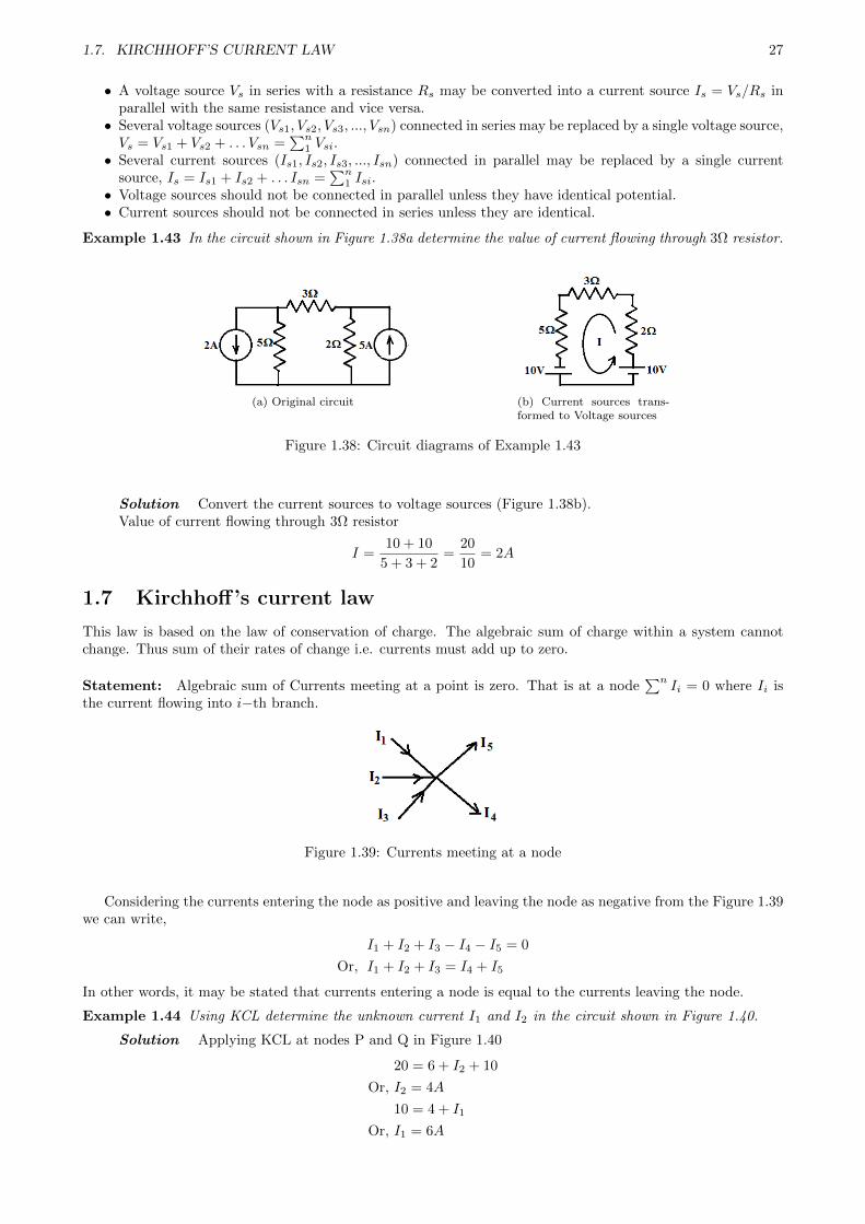
Statement: Algebraic sum of Currents meeting at a point is zero. That is at a node∑n
Ii = 0 where Ii isthe current flowing into i−th branch.
Figure 1.39: Currents meeting at a node
Considering the currents entering the node as positive and leaving the node as negative from the Figure 1.39we can write,
I1 + I2 + I3 − I4 − I5 = 0
Or, I1 + I2 + I3 = I4 + I5
In other words, it may be stated that currents entering a node is equal to the currents leaving the node.
Example 1.44 Using KCL determine the unknown current I1 and I2 in the circuit shown in Figure 1.40.
Solution Applying KCL at nodes P and Q in Figure 1.40
20 = 6 + I2 + 10
Or, I2 = 4A
10 = 4 + I1
Or, I1 = 6A

28 CHAPTER 1. BASIC CONCEPTS & LAWS
Figure 1.40: Circuit diagram for Example 1.44
1.8 Kirchhoff’s voltage law
This law is based on the law of conservation of energy. The total work done in taking a positive charge arounda closed path must add up to zero.
Statement: Algebraic sum of potential differences taken around a closed loop is zero. That is∑n
Vi=0 whereVi is the potential drop across i−the component.In other words, it may be stated that e.m.f.s around a closed loop is equal to the sum of voltage drops aroundthe loop.
Figure 1.41: A closed circuit
For the closed circuit shown in Figure 1.41,
V − V1 − V2 = 0
Or, V = IR1 + IR2
Example 1.45 Using KVL determine Va in the circuit shown in Figure 1.42.
Figure 1.42: Circuit diagram for Example1.45
Figure 1.43: Circuit diagram for Example1.45
Solution
Va = 5I
Applying KVL in Figure 1.43
10 + 2Va = (6 + 5 + 3)I = 14I =14
5Va
Or, 50 = 4Va
Or, Va =50
4= 12.5V
Example 1.46 For the circuit shown in Figure 1.44, determine Vo.

1.8. KIRCHHOFF’S VOLTAGE LAW 29
Figure 1.44: Circuit diagram for Example 1.46
Solution
Ix =15
9=
5
3A
3Ix = (6 + 4)Io
Or, Io =3
10Ix =
3
10× 5
3= 0.5 A
Vo = 4Io = 4× 0.5 = 2 volts
Example 1.47 In the network shown in Figure 1.45 determine the currents in each battery and in the 6Ωresistor.
Figure 1.45: Circuit diagrams of Example 1.47
Solution
I1 + I2 + I3 = I
10.2I1 + 6I2 + 6I3 = 100
6I1 + 9.25I2 + 6I3 = 90
6I1 + 6I2 + 11.3I3 = 80
Solving equations we get
I1 = 6.2136A
I2 = 4.9530A
I3 = 1.1504A
I = I1 + I2 + I3 = 12.3170A
Example 1.48 In the wheatstone bridge network shown in Figure 1.46a find the current through the galvanome-ter having a resistance of 1000Ω
Solution From Fig.1.46b
2200I1 − 2000I3 = 4
830I2 + 750I3 = 4
200I1 − 80I2 + 1000I3 = 0

30 CHAPTER 1. BASIC CONCEPTS & LAWS
(a) (b)
Figure 1.46: Circuit diagrams of Example 1.48
Solving equations we get
I1 = 1.8341mA
I2 = 4.8035A
I3 = 17.5µA
Current flowing through the galvanometer I3 = 17.5µA.
Example 1.49 Find Ix and Vx in the network shown in Figure 1.47a.
(a) (b)
Figure 1.47: Circuit diagrams of Example 1.49
Solution Applying KCL to Figure 1.47b
At ‘a’: 8 + I1 − 2 = 0 Or, I1 = −6A
At ‘b’: 4 + I1 − I2 = 0 Or, I2 = −2A
At ‘c’: 6− I2 + I3 = 0 Or, I3 = −8A
At ‘d’: 2 + Ix − I3 = 0 Or, Ix = −10A
Applying KVL: Vx − 10I2 + 20 = 0 Or, Vx = 40V
Example 1.50 Find V1 and V2 in the network shown in Figure 1.48.
Solution Applying KVL to Figure 1.48b
From loop a-c-d-f:
18 + 36− 20− 6− V1 − 24 = 0 Or, V1 = 4V
From loop a-b-e-f:
18− V1 − V2 − 24 = 0 Or, V2 = −10V
Example 1.51 Find the values of unknown currents I1, I2, I3 and I4 of the network shown in Figure 1.49a.

1.8. KIRCHHOFF’S VOLTAGE LAW 31
(a) (b)
Figure 1.48: Circuit diagrams of Example 1.50
(a) (b)
Figure 1.49: Circuit diagrams of Example 1.51
Solution Applying KCL to Figure 1.49b
At ‘a’: 20 + I1 − 10− 14 = 0 Or, I1 = 4A
At ‘b’: 2 + I1 + I2 − 10 = 0 Or, I2 = 4A
At ‘c’: 12− 16− I2 + I3 = 0 Or, I3 = 8A
At ‘d’: 20 + 12− 16− I4 = 0 Or, I4 = 16A
Example 1.52 Find the current in branch ac for the network shown in Figure 1.50a.
(a) (b)
Figure 1.50: Circuit diagrams of Example 1.52
Solution Let the current in Figure 1.50b through branch ‘ac’ be I1 and ‘ab’ be I2. Applying KCLat nodes ‘a’,‘d’ and ‘c’ we get branch currents
Ibc = I2 − 20
Iad = 80− I1 − I2Idc = Iad − 25 = 55− I1 − I2

32 CHAPTER 1. BASIC CONCEPTS & LAWS
Applying KVL to Figure 1.50b
At ‘a-b-c’: − 0.2I1 + 0.1I2 + 0.1(I2 − 20) = 0
Or, − 0.2I1 + 0.2I2 = 2
Or, − I1 + I2 = 10
At ‘a-d-c’: − 0.2I1 + 0.2(55− I1 − I2) + 0.1(80− I1 − I2) = 0
Or, 0.5I1 + 0.3I2 = 19
I2 = 30A
I1 = Iac = 20A
Example 1.53 Find I and VAB in the network shown in Figure 1.51a.
(a) (b)
Figure 1.51: Circuit diagrams of Example 1.53
Solution Applying KCL to Figure 1.51b
At ‘C’: 2 + 6− I1 = 0 Or, I1 = 8A
At ‘D’: 12− I1 + I2 = 0 Or, I2 = −4A
At ‘E’: 2 + 4− I = 0 Or, I2 = 6A
Applying KVL: VAB + 36 + 16− 80− 12 = 0 Or, VAB = 60V
Example 1.54 Find the voltage between A and B in the network shown in Figure 1.52a.
(a) (b)
Figure 1.52: Circuit diagrams of Example 1.54
Solution From Figure 1.52b
I =40
2 + 3 + 5= 4A
VAB = −2× 4− 10 + 4× 5 = 2V
Example 1.55 Find the voltage between A and B in the network shown in Figure 1.53a.
Solution
I1 =30
4 + 6 + 10= 1.5A
I2 =60
8 + 10 + 12= 2A
VAB = 12× 2 + 6 + (6 + 4)× 1.5 = 45V

1.8. KIRCHHOFF’S VOLTAGE LAW 33
(a) (b)
Figure 1.53: Circuit diagrams of Example 1.55