Embed Size (px)
Citation preview
Microelectronic Circuits, Sixth Edition Sedra/Smith Copyright © 2010 by Oxford University Press, Inc.
C H A P T E R 6
Basic BJT Amplifier
Configurations
Microelectronic Circuits, Sixth Edition Sedra/Smith Copyright © 2010 by Oxford University Press, Inc.
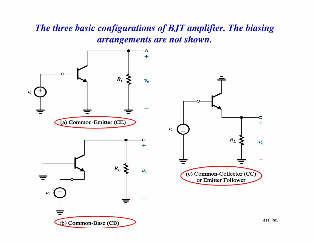
The three basic configurations of BJT amplifier. The biasing
arrangements are not shown.
Microelectronic Circuits, Sixth Edition Sedra/Smith Copyright © 2010 by Oxford University Press, Inc.
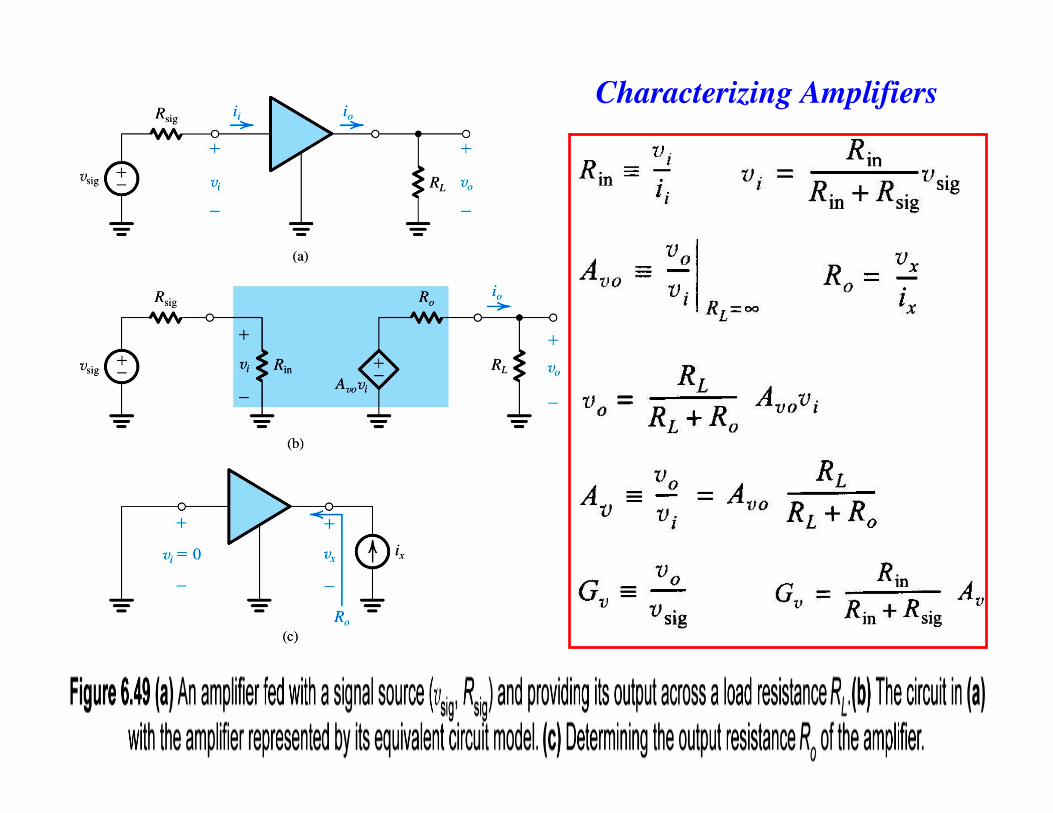
Characterizing Amplifiers
Microelectronic Circuits, Sixth Edition Sedra/Smith Copyright © 2010 by Oxford University Press, Inc.
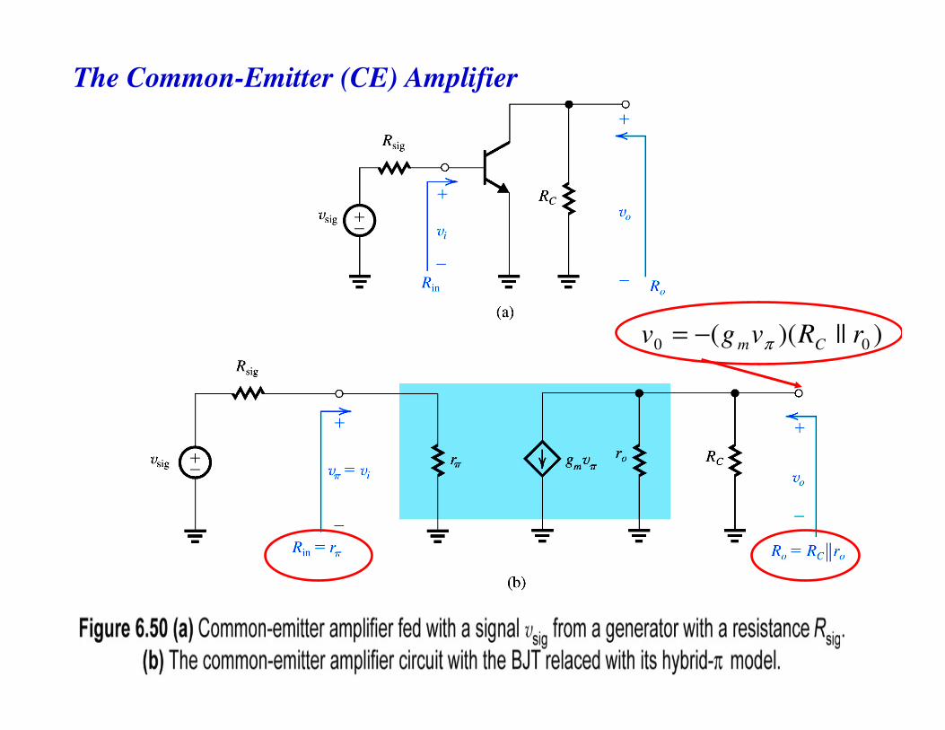
The Common-Emitter (CE) Amplifier
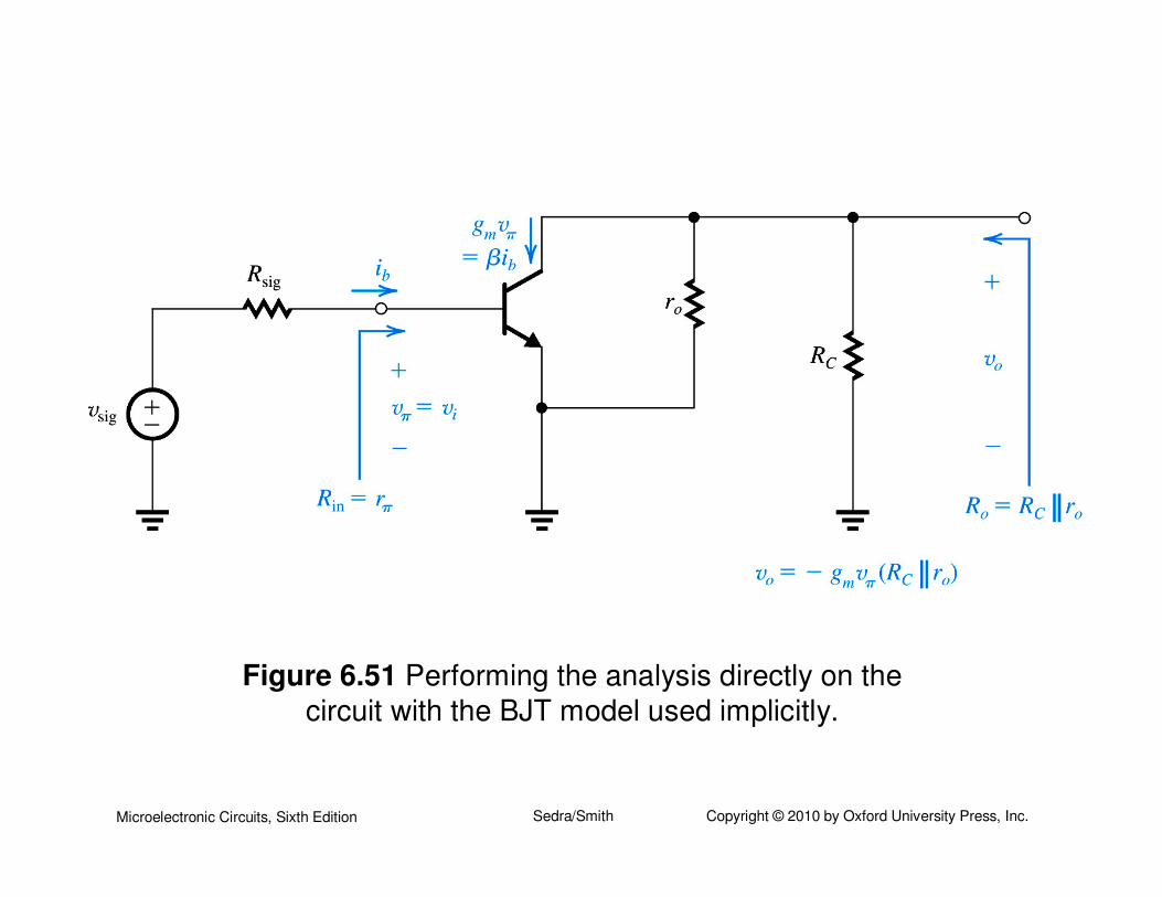
)||)(( 00 rRvgv Cm π−=
Microelectronic Circuits, Sixth Edition Sedra/Smith Copyright © 2010 by Oxford University Press, Inc.
)arg(
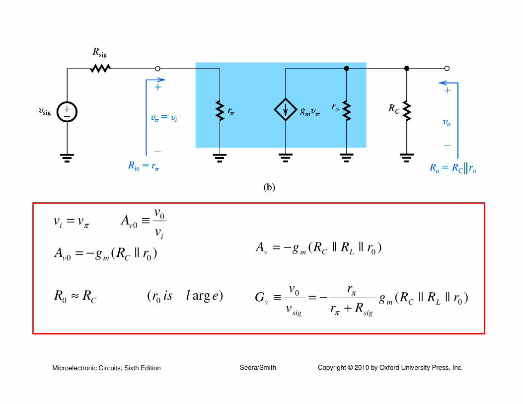
)||(
00
00
00
elisrRR
rRgA
v
vAvv
C
Cmv
i
vi
≈
−=
≡= π
)||||(
)||||(
0
0
0
rRRgRr
r
v
vG
rRRgA
LCm
sigsig
v
LCmv
+−=≡
−=
π
π
Microelectronic Circuits, Sixth Edition Sedra/Smith Copyright © 2010 by Oxford University Press, Inc.
Figure 6.51 Performing the analysis directly on the
circuit with the BJT model used implicitly.
Microelectronic Circuits, Sixth Edition Sedra/Smith Copyright © 2010 by Oxford University Press, Inc.
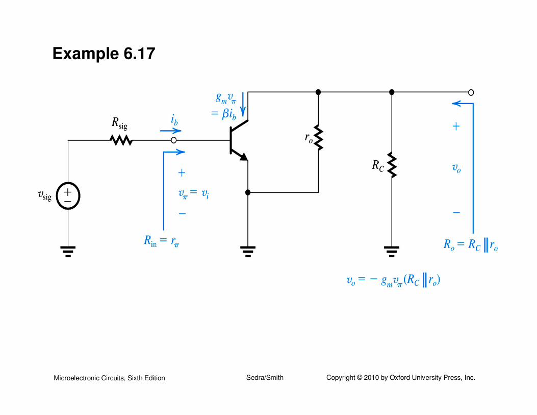
Example 6.17
Microelectronic Circuits, Sixth Edition Sedra/Smith Copyright © 2010 by Oxford University Press, Inc.
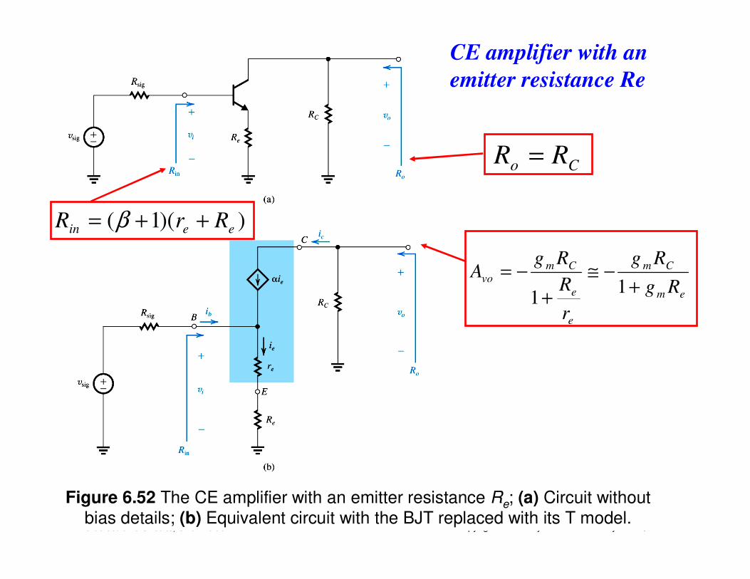
Figure 6.52 The CE amplifier with an emitter resistance Re; (a) Circuit without
bias details; (b) Equivalent circuit with the BJT replaced with its T model.
))(1( eein RrR ++= β
Co RR =
em
Cm
e
e
Cm
voRg
Rg
r
R
RgA
+−≅
+
−=1
1
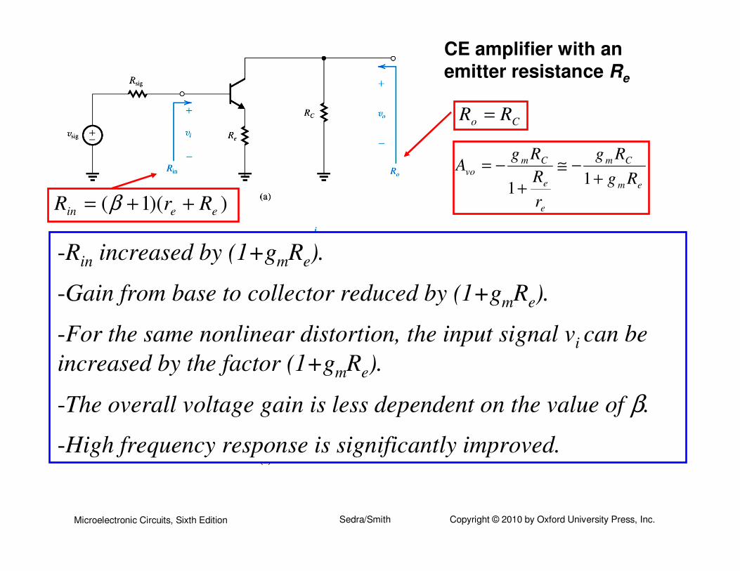
CE amplifier with an
emitter resistance Re
Microelectronic Circuits, Sixth Edition Sedra/Smith Copyright © 2010 by Oxford University Press, Inc.
))(1( eein RrR ++= β
Co RR =
em
Cm
e
e
Cm
voRg
Rg
r
R
RgA
+−≅
+
−=1
1
-Rin increased by (1+gmRe).
-Gain from base to collector reduced by (1+gmRe).
-For the same nonlinear distortion, the input signal vi can be
increased by the factor (1+gmRe).
-The overall voltage gain is less dependent on the value of β.
-High frequency response is significantly improved.
CE amplifier with an
emitter resistance Re
Microelectronic Circuits, Sixth Edition Sedra/Smith Copyright © 2010 by Oxford University Press, Inc.
Example 6.18
Microelectronic Circuits, Sixth Edition Sedra/Smith Copyright © 2010 by Oxford University Press, Inc.
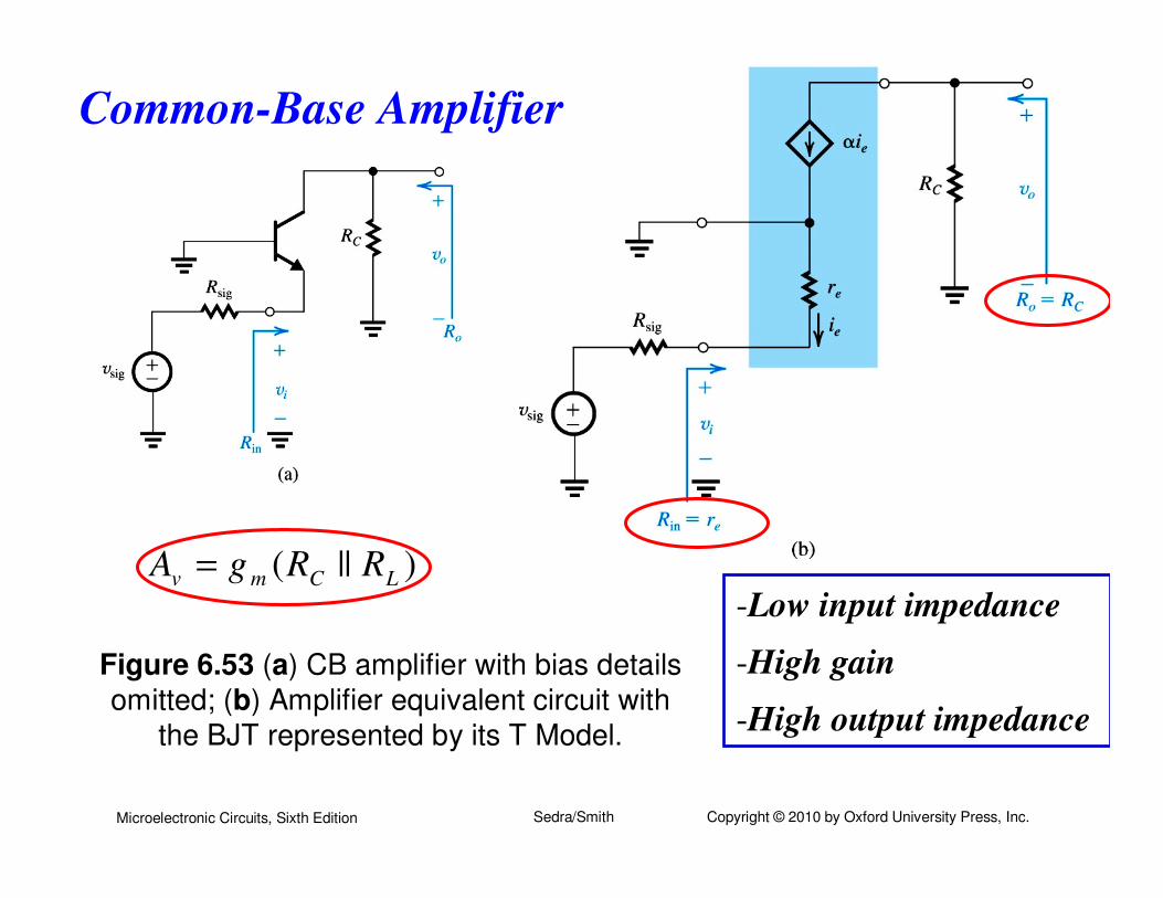
Figure 6.53 (a) CB amplifier with bias details
omitted; (b) Amplifier equivalent circuit with
the BJT represented by its T Model.
Common-Base Amplifier
)||( LCmv RRgA =-Low input impedance
-High gain
-High output impedance
Microelectronic Circuits, Sixth Edition Sedra/Smith Copyright © 2010 by Oxford University Press, Inc.
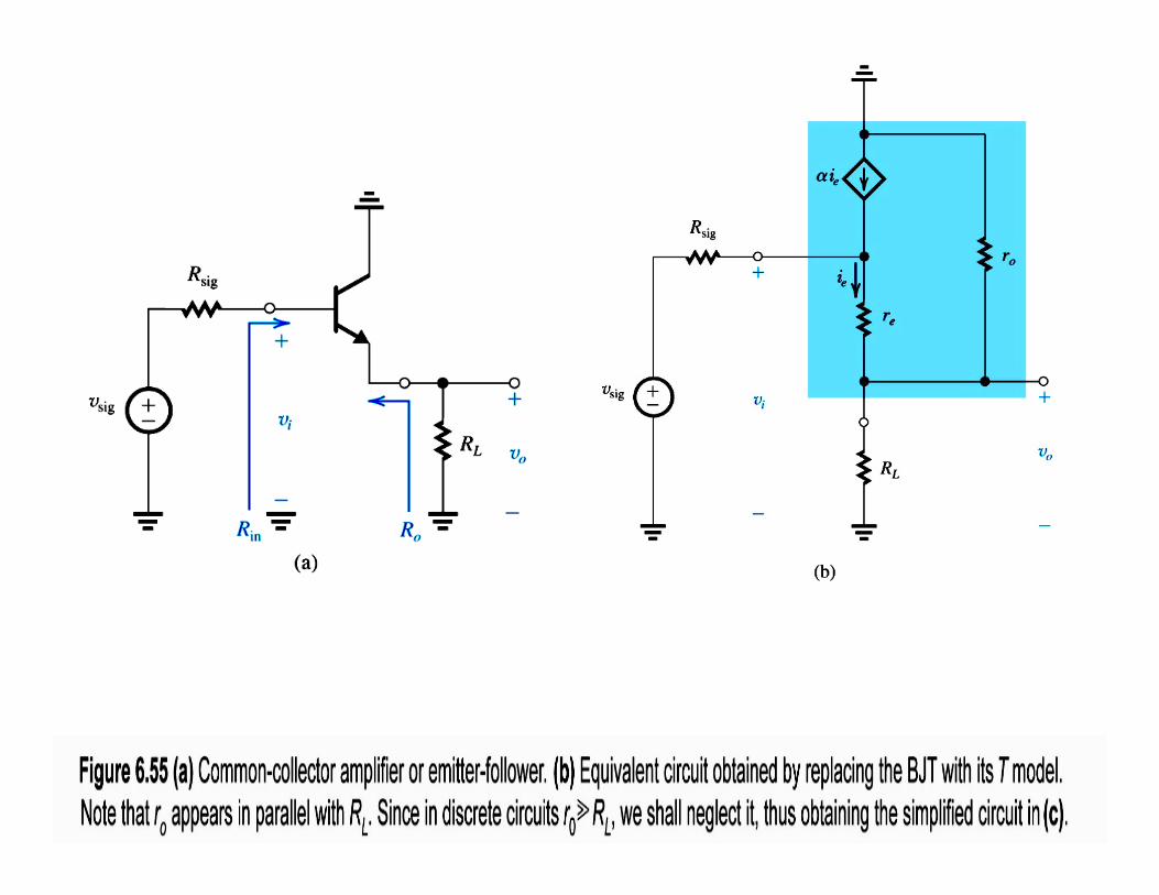
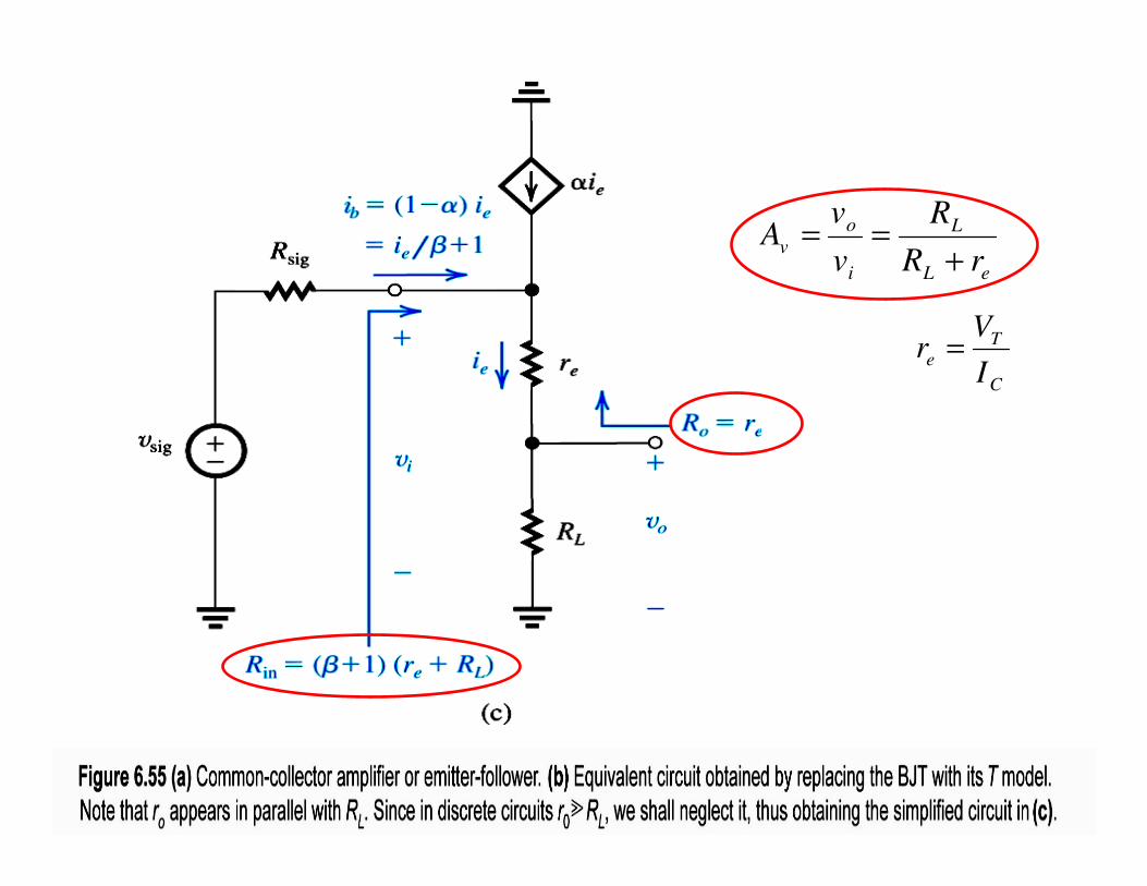
Common-Collector Amplifier or Emitter Follower

Microelectronic Circuits, Sixth Edition Sedra/Smith Copyright © 2010 by Oxford University Press, Inc.
Illustrating the need for a unity-gain buffer amplifier.
Microelectronic Circuits, Sixth Edition Sedra/Smith Copyright © 2010 by Oxford University Press, Inc.
Microelectronic Circuits, Sixth Edition Sedra/Smith Copyright © 2010 by Oxford University Press, Inc.
eL
L
i
o
vrR
R
v
vA
+==
C
T
eI
Vr =
Microelectronic Circuits, Sixth Edition Sedra/Smith Copyright © 2010 by Oxford University Press, Inc.
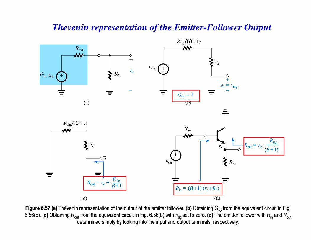
Thevenin representation of the Emitter-Follower Output
Microelectronic Circuits, Sixth Edition Sedra/Smith Copyright © 2010 by Oxford University Press, Inc.
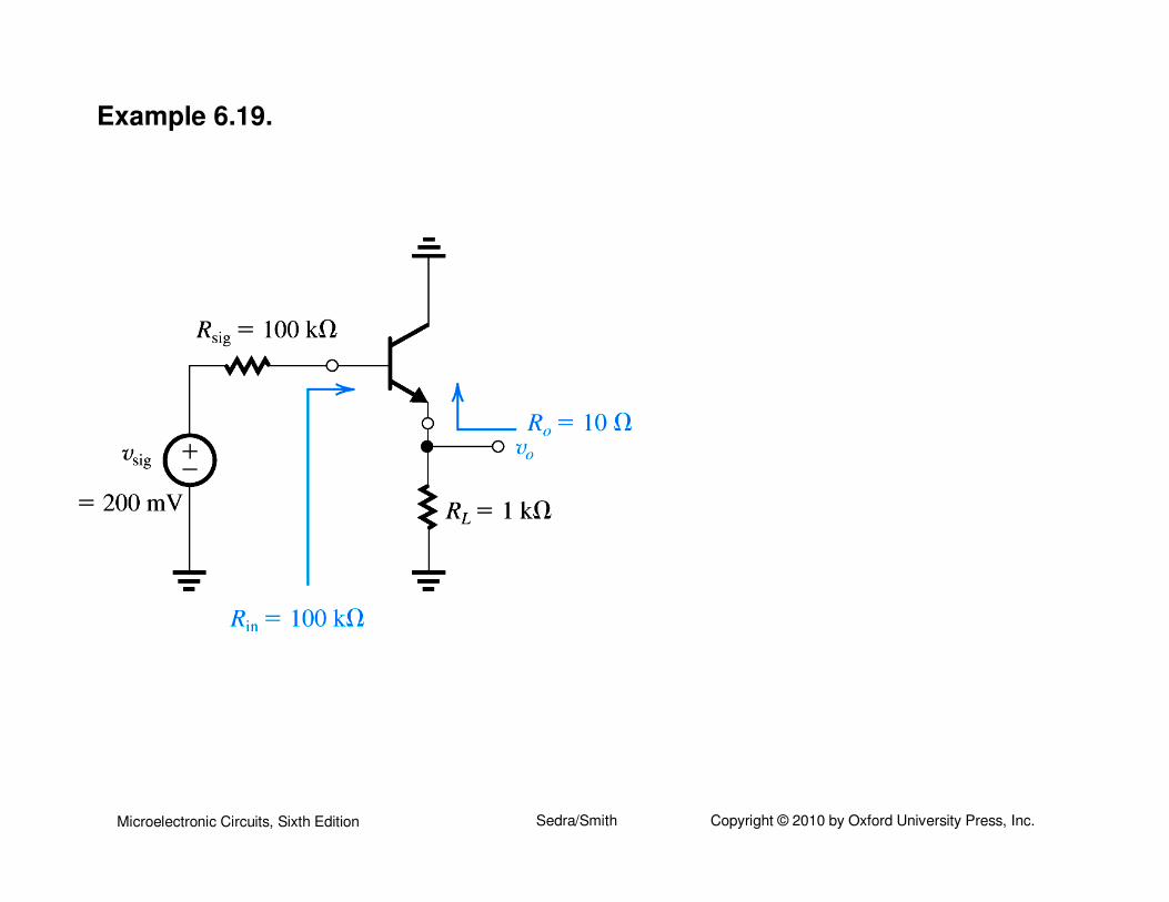
Example 6.19.
Microelectronic Circuits, Sixth Edition Sedra/Smith Copyright © 2010 by Oxford University Press, Inc.
Microelectronic Circuits, Sixth Edition Sedra/Smith Copyright © 2010 by Oxford University Press, Inc.


![BJT or FET Transistor Configurations - MITweb.mit.edu/6.101/www/s2017/handouts/L05_4.pdf · ... Common Emitter Amplifier [b] Common Collector ... complicated circuit using basic properties](https://img.dokumen.tips/doc/110x75/5b1688a87f8b9a5e6d8c7917/bjt-or-fet-transistor-configurations-common-emitter-amplifier-b-common.jpg)