Embed Size (px)
Citation preview
Product Manual
Barracuda 7200.10 Serial ATA
100402371Rev. KDecember 2007
ST3750640ASST3750840ASST3500630ASST3500830ASST3400620ASST3400820ASST3320620ASST3320820ASST3300620ASST3300820ASST3250620ASST3250820AS
ST3250410ASST3250310ASST3200820ASST3160815ASST3160310ASST3160215ASST3120815ASST3120215ASST380815ASST380215ASST340815ASST340215AS
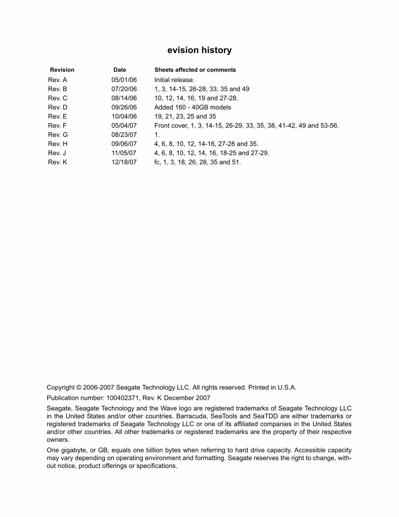
evision history
Copyright © 2006-2007 Seagate Technology LLC. All rights reserved. Printed in U.S.A.Publication number: 100402371, Rev. K December 2007Seagate, Seagate Technology and the Wave logo are registered trademarks of Seagate Technology LLC in the United States and/or other countries. Barracuda, SeaTools and SeaTDD are either trademarks or registered trademarks of Seagate Technology LLC or one of its affiliated companies in the United States and/or other countries. All other trademarks or registered trademarks are the property of their respective owners.One gigabyte, or GB, equals one billion bytes when referring to hard drive capacity. Accessible capacity may vary depending on operating environment and formatting. Seagate reserves the right to change, with-out notice, product offerings or specifications.
Revision Date Sheets affected or comments
Rev. A 05/01/06 Initial release.Rev. B 07/20/06 1, 3, 14-15, 26-28, 33, 35 and 49Rev. C 08/14/06 10, 12, 14, 16, 19 and 27-28.Rev. D 09/26/06 Added 160 - 40GB modelsRev. E 10/04/06 19, 21, 23, 25 and 35Rev. F 05/04/07 Front cover, 1, 3, 14-15, 26-29, 33, 35, 38, 41-42, 49 and 53-56.Rev. G 08/23/07 1.Rev. H 09/06/07 4, 6, 8, 10, 12, 14-16, 27-28 and 35.Rev. J 11/05/07 4, 6, 8, 10, 12, 14, 16, 18-25 and 27-29.Rev. K 12/18/07 fc, 1, 3, 18, 26, 28, 35 and 51.
Barracuda 7200.10 Serial ATA Product Manual, Rev. K i
Contents1.0 Introduction. . . . . . . . . . . . . . . . . . . . . . . . . . . . . . . . . . . . . . . . . . . . . . . . . . . . . . . . . . . . . . . . . . . 1
1.1 About the Serial ATA interface . . . . . . . . . . . . . . . . . . . . . . . . . . . . . . . . . . . . . . . . . . . . . . 2
2.0 Drive specifications . . . . . . . . . . . . . . . . . . . . . . . . . . . . . . . . . . . . . . . . . . . . . . . . . . . . . . . . . . . . 32.1 Specification summary tables . . . . . . . . . . . . . . . . . . . . . . . . . . . . . . . . . . . . . . . . . . . . . . . 32.2 Formatted capacity . . . . . . . . . . . . . . . . . . . . . . . . . . . . . . . . . . . . . . . . . . . . . . . . . . . . . . 26
2.2.1 LBA mode . . . . . . . . . . . . . . . . . . . . . . . . . . . . . . . . . . . . . . . . . . . . . . . . . . . . . 262.3 Default logical geometry . . . . . . . . . . . . . . . . . . . . . . . . . . . . . . . . . . . . . . . . . . . . . . . . . . 262.4 Recording and interface technology . . . . . . . . . . . . . . . . . . . . . . . . . . . . . . . . . . . . . . . . . 272.5 Physical characteristics . . . . . . . . . . . . . . . . . . . . . . . . . . . . . . . . . . . . . . . . . . . . . . . . . . 282.6 Seek time. . . . . . . . . . . . . . . . . . . . . . . . . . . . . . . . . . . . . . . . . . . . . . . . . . . . . . . . . . . . . . 292.7 Start/stop times . . . . . . . . . . . . . . . . . . . . . . . . . . . . . . . . . . . . . . . . . . . . . . . . . . . . . . . . . 292.8 Power specifications . . . . . . . . . . . . . . . . . . . . . . . . . . . . . . . . . . . . . . . . . . . . . . . . . . . . . 30
2.8.1 Power consumption . . . . . . . . . . . . . . . . . . . . . . . . . . . . . . . . . . . . . . . . . . . . . . 302.8.2 Conducted noise . . . . . . . . . . . . . . . . . . . . . . . . . . . . . . . . . . . . . . . . . . . . . . . . 312.8.3 Voltage tolerance . . . . . . . . . . . . . . . . . . . . . . . . . . . . . . . . . . . . . . . . . . . . . . . . 312.8.4 Power-management modes. . . . . . . . . . . . . . . . . . . . . . . . . . . . . . . . . . . . . . . . 32
2.9 Environmental specifications . . . . . . . . . . . . . . . . . . . . . . . . . . . . . . . . . . . . . . . . . . . . . . . 332.9.1 Ambient temperature . . . . . . . . . . . . . . . . . . . . . . . . . . . . . . . . . . . . . . . . . . . . . 332.9.2 Temperature gradient. . . . . . . . . . . . . . . . . . . . . . . . . . . . . . . . . . . . . . . . . . . . . 332.9.3 Humidity . . . . . . . . . . . . . . . . . . . . . . . . . . . . . . . . . . . . . . . . . . . . . . . . . . . . . . . 332.9.4 Altitude . . . . . . . . . . . . . . . . . . . . . . . . . . . . . . . . . . . . . . . . . . . . . . . . . . . . . . . . 332.9.5 Shock . . . . . . . . . . . . . . . . . . . . . . . . . . . . . . . . . . . . . . . . . . . . . . . . . . . . . . . . . 332.9.6 Vibration . . . . . . . . . . . . . . . . . . . . . . . . . . . . . . . . . . . . . . . . . . . . . . . . . . . . . . . 34
2.10 Acoustics . . . . . . . . . . . . . . . . . . . . . . . . . . . . . . . . . . . . . . . . . . . . . . . . . . . . . . . . . . . . . . 352.10.1 Test for Prominent Discrete Tones (PDTs) . . . . . . . . . . . . . . . . . . . . . . . . . . . . 35
2.11 Electromagnetic immunity . . . . . . . . . . . . . . . . . . . . . . . . . . . . . . . . . . . . . . . . . . . . . . . . . 362.12 Reliability . . . . . . . . . . . . . . . . . . . . . . . . . . . . . . . . . . . . . . . . . . . . . . . . . . . . . . . . . . . . . . 37
2.12.1 Annualized Failure Rate (AFR) and Mean Time Between Failures (MTBF) . . . 372.13 Agency certification . . . . . . . . . . . . . . . . . . . . . . . . . . . . . . . . . . . . . . . . . . . . . . . . . . . . . . 37
2.13.1 Safety certification . . . . . . . . . . . . . . . . . . . . . . . . . . . . . . . . . . . . . . . . . . . . . . . 372.13.2 Electromagnetic compatibility. . . . . . . . . . . . . . . . . . . . . . . . . . . . . . . . . . . . . . . 372.13.3 FCC verification . . . . . . . . . . . . . . . . . . . . . . . . . . . . . . . . . . . . . . . . . . . . . . . . . 38
2.14 Environmental protection. . . . . . . . . . . . . . . . . . . . . . . . . . . . . . . . . . . . . . . . . . . . . . . . . . 392.14.1 European Union Restriction of Hazardous Substances (RoHS) Directive . . . . . 392.14.2 China Restriction of Hazardous Substances (RoHS) Directive . . . . . . . . . . . . . 39
2.15 Corrosive environment . . . . . . . . . . . . . . . . . . . . . . . . . . . . . . . . . . . . . . . . . . . . . . . . . . . 39
3.0 Configuring and mounting the drive . . . . . . . . . . . . . . . . . . . . . . . . . . . . . . . . . . . . . . . . . . . . . 413.1 Handling and static-discharge precautions . . . . . . . . . . . . . . . . . . . . . . . . . . . . . . . . . . . . 413.2 Configuring the drive . . . . . . . . . . . . . . . . . . . . . . . . . . . . . . . . . . . . . . . . . . . . . . . . . . . . . 423.3 Serial ATA cables and connectors . . . . . . . . . . . . . . . . . . . . . . . . . . . . . . . . . . . . . . . . . . 423.4 Drive mounting . . . . . . . . . . . . . . . . . . . . . . . . . . . . . . . . . . . . . . . . . . . . . . . . . . . . . . . . . 43
4.0 Serial ATA (SATA) interface . . . . . . . . . . . . . . . . . . . . . . . . . . . . . . . . . . . . . . . . . . . . . . . . . . . . 454.1 Hot-Plug compatibility . . . . . . . . . . . . . . . . . . . . . . . . . . . . . . . . . . . . . . . . . . . . . . . . . . . . 454.2 Serial ATA device plug connector pin definitions. . . . . . . . . . . . . . . . . . . . . . . . . . . . . . . . 464.3 Supported ATA commands . . . . . . . . . . . . . . . . . . . . . . . . . . . . . . . . . . . . . . . . . . . . . . . . 47
4.3.1 Identify Device command. . . . . . . . . . . . . . . . . . . . . . . . . . . . . . . . . . . . . . . . . . 494.3.2 Set Features command . . . . . . . . . . . . . . . . . . . . . . . . . . . . . . . . . . . . . . . . . . . 534.3.3 S.M.A.R.T. commands . . . . . . . . . . . . . . . . . . . . . . . . . . . . . . . . . . . . . . . . . . . . 54
5.0 Seagate Technology support services. . . . . . . . . . . . . . . . . . . . . . . . . . . . . . . . . . . . . . . . . . . . 55

ii Barracuda 7200.10 Serial ATA Product Manual, Rev. K
Barracuda 7200.10 Serial ATA Product Manual, Rev. K iii
List of Figures
Figure 1. Typical 5V startup and operation current profile . . . . . . . . . . . . . . . . . . . . . . . . . . . . . . . . . . . 31Figure 2. Typical 12V startup and operation current profile . . . . . . . . . . . . . . . . . . . . . . . . . . . . . . . . . . 31Figure 3. Serial ATA connectors . . . . . . . . . . . . . . . . . . . . . . . . . . . . . . . . . . . . . . . . . . . . . . . . . . . . . . 42Figure 4. Attaching SATA cabling . . . . . . . . . . . . . . . . . . . . . . . . . . . . . . . . . . . . . . . . . . . . . . . . . . . . . 42Figure 5. Mounting dimensions for 750-200 GB models (except ST3250410AS and ST3250310AS) . 43Figure 6. Mounting dimensions for 160-40 GB models (including ST3250410AS and ST3250310AS) 44

Barracuda 7200.10 Serial ATA Product Manual, Rev. K 1
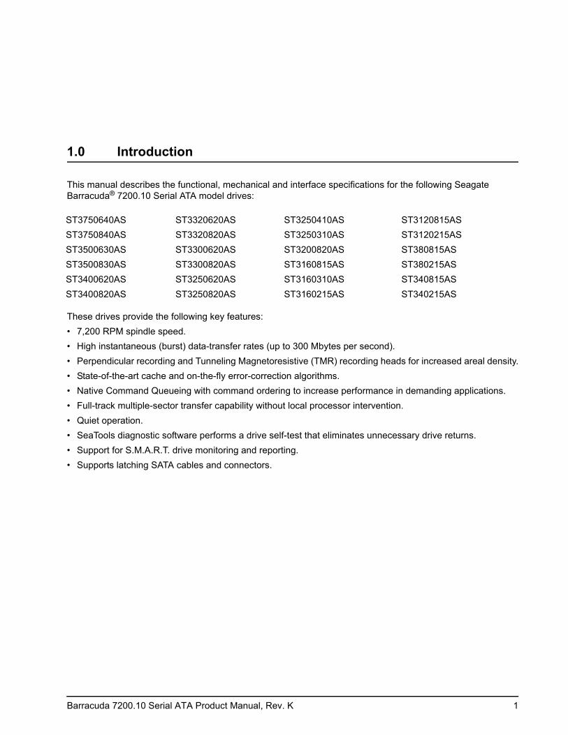
1.0 Introduction
This manual describes the functional, mechanical and interface specifications for the following Seagate Barracuda® 7200.10 Serial ATA model drives:
These drives provide the following key features:• 7,200 RPM spindle speed.• High instantaneous (burst) data-transfer rates (up to 300 Mbytes per second).• Perpendicular recording and Tunneling Magnetoresistive (TMR) recording heads for increased areal density.• State-of-the-art cache and on-the-fly error-correction algorithms.• Native Command Queueing with command ordering to increase performance in demanding applications.• Full-track multiple-sector transfer capability without local processor intervention.• Quiet operation.• SeaTools diagnostic software performs a drive self-test that eliminates unnecessary drive returns.• Support for S.M.A.R.T. drive monitoring and reporting.• Supports latching SATA cables and connectors.
ST3750640AS ST3320620AS ST3250410AS ST3120815ASST3750840AS ST3320820AS ST3250310AS ST3120215ASST3500630AS ST3300620AS ST3200820AS ST380815ASST3500830AS ST3300820AS ST3160815AS ST380215ASST3400620AS ST3250620AS ST3160310AS ST340815ASST3400820AS ST3250820AS ST3160215AS ST340215AS
2 Barracuda 7200.10 Serial ATA Product Manual, Rev. K
1.1 About the Serial ATA interface
The Serial ATA interface provides several advantages over the traditional (parallel) ATA interface. The primary advantages include:• Easy installation and configuration with true plug-and-play connectivity. It is not necessary to set any jump-
ers or other configuration options.• Thinner and more flexible cabling for improved enclosure airflow and ease of installation.• Scalability to higher performance levels.
In addition, Serial ATA makes the transition from parallel ATA easy by providing legacy software support. Serial ATA was designed to allow you to install a Serial ATA host adapter and Serial ATA disc drive in your current system and expect all of your existing applications to work as normal.
The Serial ATA interface connects each disc drive in a point-to-point configuration with the Serial ATA host adapter. There is no master/slave relationship with Serial ATA devices like there is with parallel ATA. If two drives are attached on one Serial ATA host adapter, the host operating system views the two devices as if they were both “masters” on two separate ports. This essentially means both drives behave as if they are Device 0 (master) devices.
Note. The host adapter may, optionally, emulate a master/slave environment to host software where two devices on separate Serial ATA ports are represented to host software as a Device 0 (master) and Device 1 (slave) accessed at the same set of host bus addresses. A host adapter that emulates a master/slave environment manages two sets of shadow registers. This is not a typical Serial ATA environment.
The Serial ATA host adapter and drive share the function of emulating parallel ATA device behavior to provide backward compatibility with existing host systems and software. The Command and Control Block registers, PIO and DMA data transfers, resets, and interrupts are all emulated.
The Serial ATA host adapter contains a set of registers that shadow the contents of the traditional device regis-ters, referred to as the Shadow Register Block. All Serial ATA devices behave like Device 0 devices. For addi-tional information about how Serial ATA emulates parallel ATA, refer to the “Serial ATA: High Speed Serialized AT Attachment” specification. The specification can be downloaded from www.serialata.org.
Barracuda 7200.10 Serial ATA Product Manual, Rev. K 3
2.0 Drive specifications
Unless otherwise noted, all specifications are measured under ambient conditions, at 25°C, and nominal power. For convenience, the phrases the drive and this drive are used throughout this manual to indicate the following drive models:
2.1 Specification summary tables
The specifications listed in the following tables are for quick reference. For details on specification measure-ment or definition, see the appropriate section of this manual.
ST3750640AS ST3320620AS ST3250410AS ST3120815ASST3750840AS ST3320820AS ST3250310AS ST3120215ASST3500630AS ST3300620AS ST3200820AS ST380815ASST3500830AS ST3300820AS ST3160815AS ST380215ASST3400620AS ST3250620AS ST3160310AS ST340815ASST3400820AS ST3250820AS ST3160215AS ST340215AS

4 Barracuda 7200.10 Serial ATA Product Manual, Rev. K
Table 1: Drive specifications summary for 750 Gbyte models
Drive specification ST3750640AS ST3750840AS
Formatted capacitty (512 bytes/sector)* 750 Gbytes
Guaranteed sectors 1,465,149,168
Heads 8
Discs 4
Bytes per sector 512
Default sectors per track 63
Default read/write heads 16
Default cylinders 16,383
Recording density 769 kbits/in avg
Track density 141 ktracks/in avg
Areal density 109 Gbits/in2 avg
Spindle speed 7,200 RPM
Internal data transfer rate 1,030 Mbits/sec max
Sustained data transfer rate OD (read) 78 Mbytes/sec max
I/O data-transfer rate 300 Mbytes/sec max
ATA data-transfer modes supported PIO modes 0–4 Multiword DMA modes 0–2 Ultra DMA modes 0–6
Cache buffer 16 Mbytes 8 Mbytes
Height (max) 26.1 mm (1.028 inches)
Width (max) 101.85 mm (4.010 inches)
Length (max) 146.99 mm (5.787 inches)
Weight (typical) 720 grams (1.59 lbs)
Average latency 4.16 msec
Power-on to ready 15 sec max
Standby to ready 15 sec max
Track-to-track seek time <0.8 msec typical read; <1.0 msec typical write
Average seek, read <8.5 msec typical
Average seek, write <10.0 msec typical
Startup current (typical) 12V (peak) 2.8 amps
Voltage tolerance (including noise) 5V ± 5% 12V ± 10%
Ambient temperature 0° to 60°C (operating) –40° to 70°C (nonoperating)
Temperature gradient 20°C per hour max (operating) 30°C per hour max (nonoperating)
Relative humidity 5% to 90% (operating) 5% to 95% (nonoperating)
Relative humidity gradient 30% per hour max
Wet bulb temperature 37.7°C max (operating) 37.7°C max (nonoperating)
Altitude, operating –60.96 m to 3,048 m (–200 ft. to 10,000+ ft.)
Altitude, nonoperating (below mean sea level, max)
–60.96 m to 12,192 m (–200 ft. to 40,000+ ft.)
Operational Shock 68 Gs at 2 msec max
Non-Operational Shock 300 Gs at 2 msec max

Barracuda 7200.10 Serial ATA Product Manual, Rev. K 5
*One Gbyte equals one billion bytes when referring to hard drive capacity. Accessible capacity may vary depending on operating environment and formatting.
**During periods of drive idle, some offline activity may occur according to the S.M.A.R.T. specification, which may increase acoustic and power to operational levels.
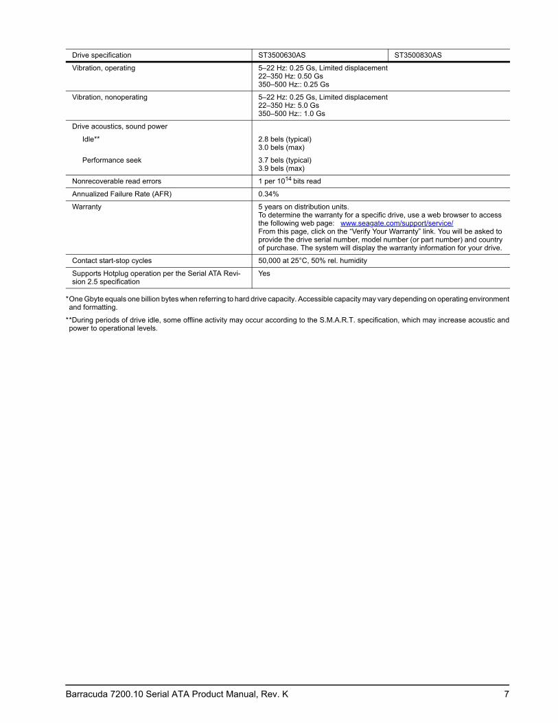
Vibration, operating 5–22 Hz: 0.25 Gs, Limited displacement 22–350 Hz: 0.50 Gs 350–500 Hz:: 0.25 Gs
Vibration, nonoperating 5–22 Hz: 0.25 Gs, Limited displacement 22–350 Hz: 5.0 Gs 350–500 Hz:: 1.0 Gs
Drive acoustics, sound power
Idle** 2.8 bels (typical) 3.0 bels (max)
Performance seek 3.7 bels (typical) 3.9 bels (max)
Nonrecoverable read errors 1 per 1014 bits read
Annualized Failure Rate (AFR) 0.34%
Warranty 5 years on distribution units.To determine the warranty for a specific drive, use a web browser to access the following web page: www.seagate.com/support/service/From this page, click on the “Verify Your Warranty” link. You will be asked to provide the drive serial number, model number (or part number) and country of purchase. The system will display the warranty information for your drive.
Contact start-stop cycles 50,000 at 25°C, 50% rel. humidity
Supports Hotplug operation per the Serial ATA Revision 2.5 specification
Yes
Drive specification ST3750640AS ST3750840AS
6 Barracuda 7200.10 Serial ATA Product Manual, Rev. K
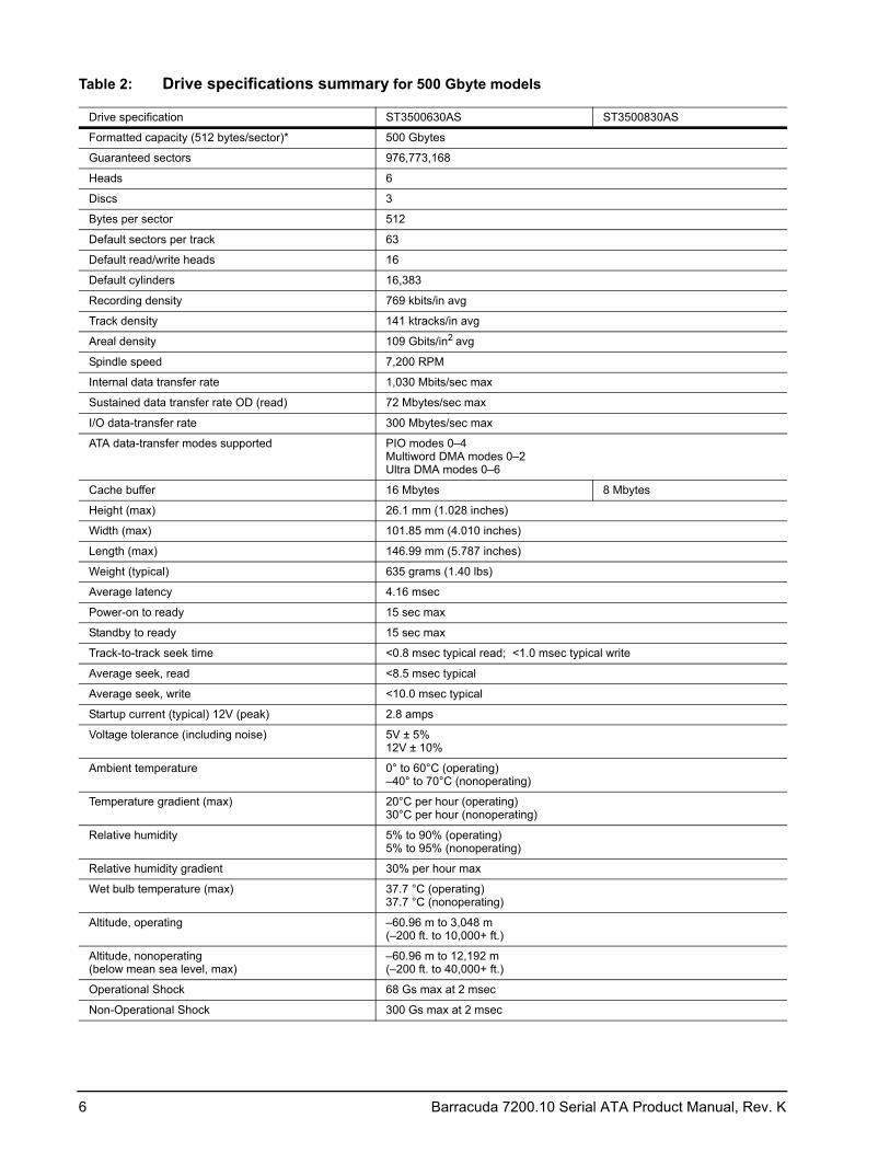
Table 2: Drive specifications summary for 500 Gbyte models
Drive specification ST3500630AS ST3500830AS
Formatted capacity (512 bytes/sector)* 500 Gbytes
Guaranteed sectors 976,773,168
Heads 6
Discs 3
Bytes per sector 512
Default sectors per track 63
Default read/write heads 16
Default cylinders 16,383
Recording density 769 kbits/in avg
Track density 141 ktracks/in avg
Areal density 109 Gbits/in2 avg
Spindle speed 7,200 RPM
Internal data transfer rate 1,030 Mbits/sec max
Sustained data transfer rate OD (read) 72 Mbytes/sec max
I/O data-transfer rate 300 Mbytes/sec max
ATA data-transfer modes supported PIO modes 0–4 Multiword DMA modes 0–2 Ultra DMA modes 0–6
Cache buffer 16 Mbytes 8 Mbytes
Height (max) 26.1 mm (1.028 inches)
Width (max) 101.85 mm (4.010 inches)
Length (max) 146.99 mm (5.787 inches)
Weight (typical) 635 grams (1.40 lbs)
Average latency 4.16 msec
Power-on to ready 15 sec max
Standby to ready 15 sec max
Track-to-track seek time <0.8 msec typical read; <1.0 msec typical write
Average seek, read <8.5 msec typical
Average seek, write <10.0 msec typical
Startup current (typical) 12V (peak) 2.8 amps
Voltage tolerance (including noise) 5V ± 5% 12V ± 10%
Ambient temperature 0° to 60°C (operating) –40° to 70°C (nonoperating)
Temperature gradient (max) 20°C per hour (operating) 30°C per hour (nonoperating)
Relative humidity 5% to 90% (operating) 5% to 95% (nonoperating)
Relative humidity gradient 30% per hour max
Wet bulb temperature (max) 37.7 °C (operating) 37.7 °C (nonoperating)
Altitude, operating –60.96 m to 3,048 m (–200 ft. to 10,000+ ft.)
Altitude, nonoperating (below mean sea level, max)
–60.96 m to 12,192 m (–200 ft. to 40,000+ ft.)
Operational Shock 68 Gs max at 2 msec
Non-Operational Shock 300 Gs max at 2 msec
Barracuda 7200.10 Serial ATA Product Manual, Rev. K 7
*One Gbyte equals one billion bytes when referring to hard drive capacity. Accessible capacity may vary depending on operating environment and formatting.
**During periods of drive idle, some offline activity may occur according to the S.M.A.R.T. specification, which may increase acoustic and power to operational levels.
Vibration, operating 5–22 Hz: 0.25 Gs, Limited displacement 22–350 Hz: 0.50 Gs 350–500 Hz:: 0.25 Gs
Vibration, nonoperating 5–22 Hz: 0.25 Gs, Limited displacement 22–350 Hz: 5.0 Gs 350–500 Hz:: 1.0 Gs
Drive acoustics, sound power
Idle** 2.8 bels (typical) 3.0 bels (max)
Performance seek 3.7 bels (typical) 3.9 bels (max)
Nonrecoverable read errors 1 per 1014 bits read
Annualized Failure Rate (AFR) 0.34%
Warranty 5 years on distribution units.To determine the warranty for a specific drive, use a web browser to access the following web page: www.seagate.com/support/service/From this page, click on the “Verify Your Warranty” link. You will be asked to provide the drive serial number, model number (or part number) and country of purchase. The system will display the warranty information for your drive.
Contact start-stop cycles 50,000 at 25°C, 50% rel. humidity
Supports Hotplug operation per the Serial ATA Revi-sion 2.5 specification
Yes
Drive specification ST3500630AS ST3500830AS

8 Barracuda 7200.10 Serial ATA Product Manual, Rev. K
Table 3: Drive specifications summary for 400 Gbyte models
Drive specification ST3400620AS ST3400820AS
Formatted capacity (512 bytes/sector)* 400 Gbytes
Guaranteed sectors 781,422,768
Heads 5
Doscs 3
Bytes per sector 512
Default sectors per track 63
Default read/write heads 16
Default cylinders 16,383
Recording density 769 kbits/in avg
Track density 141 ktracks/in avg
Areal density 109 Gbits/in2 avg
Spindle speed 7,200 RPM
Internal data transfer rate 1,030 Mbits/sec max
Sustained data transfer rate OD (read) 72 Mbytes/sec max
I/O data-transfer rate 300 Mbytes/sec max
ATA data-transfer modes supported PIO modes 0–4 Multiword DMA modes 0–2 Ultra DMA modes 0–6
Cache buffer 16 Mbytes 8 Mbytes
Height (max) 26.1 mm (1.028 inches)
Width (max) 101.85 mm (4.010 inches)
Length (max) 146.99 mm (5.787 inches)
Weight (typical) 635 grams (1.40 lbs)
Average latency 4.16 msec
Power-on to ready 15 sec max
Standby to ready 15 sec max
Track-to-track seek time <0.8 msec typical read; <1.0 msec typical write
Average seek, read <8.5 msec typical
Average seek, write <10.0 msec typical
Startup current (typical) 12V (peak) 2.8 amps
Voltage tolerance (including noise) 5V ± 5% 12V ± 10%
Ambient temperature 0° to 60°C (operating) –40° to 70°C (nonoperating)
Temperature gradient 20°C per hour max (operating) 30°C per hour max (nonoperating)
Relative humidity 5% to 90% (operating) 5% to 95% (nonoperating)
Relative humidity gradient 30% per hour max
Wet bulb temperature 37.7 °C max (operating) 37.7 °C max (nonoperating)
Altitude, operating –60.96 m to 3,048 m (–200 ft. to 10,000+ ft.)
Altitude, nonoperating (below mean sea level, max)
–60.96 m to 12,192 m (–200 ft. to 40,000+ ft.)
Operational Shock 68 Gs max at 2 msec
Non-Operational Shock 300 Gs max at 2 msec
Barracuda 7200.10 Serial ATA Product Manual, Rev. K 9
*One Gbyte equals one billion bytes when referring to hard drive capacity. Accessible capacity may vary depending on operating environment and formatting.
**During periods of drive idle, some offline activity may occur according to the S.M.A.R.T. specification, which may increase acoustic and power to operational levels.
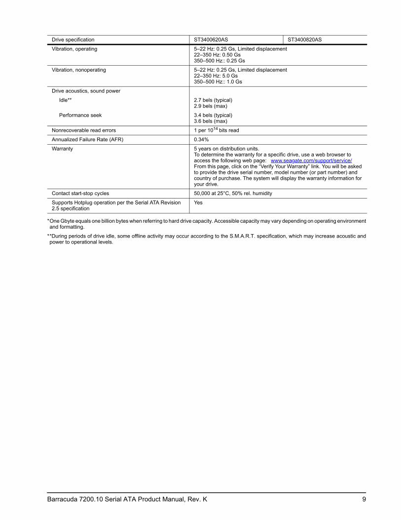
Vibration, operating 5–22 Hz: 0.25 Gs, Limited displacement 22–350 Hz: 0.50 Gs 350–500 Hz:: 0.25 Gs
Vibration, nonoperating 5–22 Hz: 0.25 Gs, Limited displacement 22–350 Hz: 5.0 Gs 350–500 Hz:: 1.0 Gs
Drive acoustics, sound power
Idle** 2.7 bels (typical) 2.9 bels (max)
Performance seek 3.4 bels (typical) 3.6 bels (max)
Nonrecoverable read errors 1 per 1014 bits read
Annualized Failure Rate (AFR) 0.34%
Warranty 5 years on distribution units.To determine the warranty for a specific drive, use a web browser to access the following web page: www.seagate.com/support/service/From this page, click on the “Verify Your Warranty” link. You will be asked to provide the drive serial number, model number (or part number) and country of purchase. The system will display the warranty information for your drive.
Contact start-stop cycles 50,000 at 25°C, 50% rel. humidity
Supports Hotplug operation per the Serial ATA Revision 2.5 specification
Yes
Drive specification ST3400620AS ST3400820AS
10 Barracuda 7200.10 Serial ATA Product Manual, Rev. K
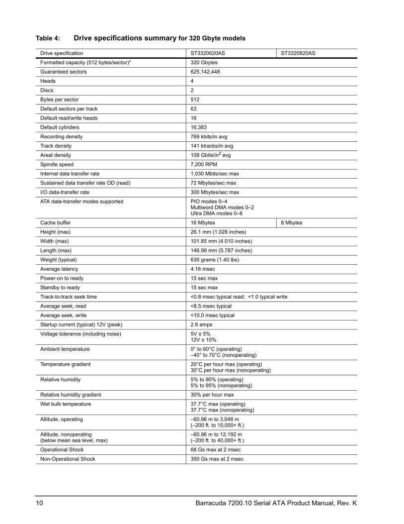
Table 4: Drive specifications summary for 320 Gbyte models
Drive specification ST3320620AS ST3320820AS
Formatted capacity (512 bytes/sector)* 320 Gbytes
Guaranteed sectors 625,142,448
Heads 4
Discs 2
Bytes per sector 512
Default sectors per track 63
Default read/write heads 16
Default cylinders 16,383
Recording density 769 kbits/in avg
Track density 141 ktracks/in avg
Areal density 109 Gbits/in2 avg
Spindle speed 7,200 RPM
Internal data transfer rate 1,030 Mbits/sec max
Sustained data transfer rate OD (read) 72 Mbytes/sec max
I/O data-transfer rate 300 Mbytes/sec max
ATA data-transfer modes supported PIO modes 0–4 Multiword DMA modes 0–2 Ultra DMA modes 0–6
Cache buffer 16 Mbytes 8 Mbytes
Height (max) 26.1 mm (1.028 inches)
Width (max) 101.85 mm (4.010 inches)
Length (max) 146.99 mm (5.787 inches)
Weight (typical) 635 grams (1.40 lbs)
Average latency 4.16 msec
Power-on to ready 15 sec max
Standby to ready 15 sec max
Track-to-track seek time <0.8 msec typical read; <1.0 typical write
Average seek, read <8.5 msec typical
Average seek, write <10.0 msec typical
Startup current (typical) 12V (peak) 2.8 amps
Voltage tolerance (including noise) 5V ± 5% 12V ± 10%
Ambient temperature 0° to 60°C (operating) –40° to 70°C (nonoperating)
Temperature gradient 20°C per hour max (operating) 30°C per hour max (nonoperating)
Relative humidity 5% to 90% (operating) 5% to 95% (nonoperating)
Relative humidity gradient 30% per hour max
Wet bulb temperature 37.7°C max (operating) 37.7°C max (nonoperating)
Altitude, operating –60.96 m to 3,048 m (–200 ft. to 10,000+ ft.)
Altitude, nonoperating (below mean sea level, max)
–60.96 m to 12,192 m (–200 ft. to 40,000+ ft.)
Operational Shock 68 Gs max at 2 msec
Non-Operational Shock 350 Gs max at 2 msec
Barracuda 7200.10 Serial ATA Product Manual, Rev. K 11
*One Gbyte equals one billion bytes when referring to hard drive capacity. Accessible capacity may vary depending on operating environment and formatting.
**During periods of drive idle, some offline activity may occur according to the S.M.A.R.T. specification, which may increase acoustic and power to operational levels.
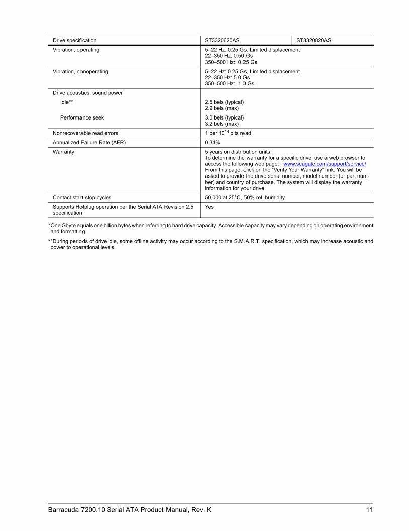
Vibration, operating 5–22 Hz: 0.25 Gs, Limited displacement 22–350 Hz: 0.50 Gs 350–500 Hz:: 0.25 Gs
Vibration, nonoperating 5–22 Hz: 0.25 Gs, Limited displacement 22–350 Hz: 5.0 Gs 350–500 Hz:: 1.0 Gs
Drive acoustics, sound power
Idle** 2.5 bels (typical) 2.9 bels (max)
Performance seek 3.0 bels (typical) 3.2 bels (max)
Nonrecoverable read errors 1 per 1014 bits read
Annualized Failure Rate (AFR) 0.34%
Warranty 5 years on distribution units.To determine the warranty for a specific drive, use a web browser to access the following web page: www.seagate.com/support/service/From this page, click on the “Verify Your Warranty” link. You will be asked to provide the drive serial number, model number (or part num-ber) and country of purchase. The system will display the warranty information for your drive.
Contact start-stop cycles 50,000 at 25°C, 50% rel. humidity
Supports Hotplug operation per the Serial ATA Revision 2.5 specification
Yes
Drive specification ST3320620AS ST3320820AS
12 Barracuda 7200.10 Serial ATA Product Manual, Rev. K
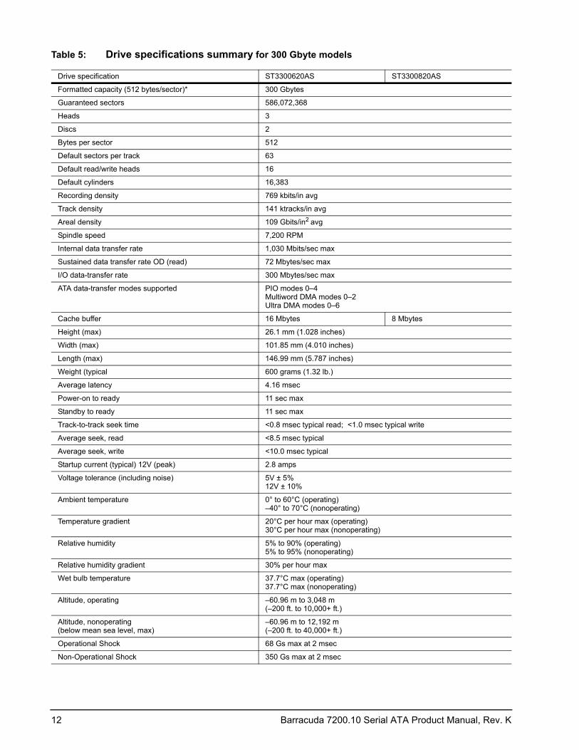
Table 5: Drive specifications summary for 300 Gbyte models
Drive specification ST3300620AS ST3300820AS
Formatted capacity (512 bytes/sector)* 300 Gbytes
Guaranteed sectors 586,072,368
Heads 3
Discs 2
Bytes per sector 512
Default sectors per track 63
Default read/write heads 16
Default cylinders 16,383
Recording density 769 kbits/in avg
Track density 141 ktracks/in avg
Areal density 109 Gbits/in2 avg
Spindle speed 7,200 RPM
Internal data transfer rate 1,030 Mbits/sec max
Sustained data transfer rate OD (read) 72 Mbytes/sec max
I/O data-transfer rate 300 Mbytes/sec max
ATA data-transfer modes supported PIO modes 0–4 Multiword DMA modes 0–2 Ultra DMA modes 0–6
Cache buffer 16 Mbytes 8 Mbytes
Height (max) 26.1 mm (1.028 inches)
Width (max) 101.85 mm (4.010 inches)
Length (max) 146.99 mm (5.787 inches)
Weight (typical 600 grams (1.32 lb.)
Average latency 4.16 msec
Power-on to ready 11 sec max
Standby to ready 11 sec max
Track-to-track seek time <0.8 msec typical read; <1.0 msec typical write
Average seek, read <8.5 msec typical
Average seek, write <10.0 msec typical
Startup current (typical) 12V (peak) 2.8 amps
Voltage tolerance (including noise) 5V ± 5% 12V ± 10%
Ambient temperature 0° to 60°C (operating) –40° to 70°C (nonoperating)
Temperature gradient 20°C per hour max (operating) 30°C per hour max (nonoperating)
Relative humidity 5% to 90% (operating) 5% to 95% (nonoperating)
Relative humidity gradient 30% per hour max
Wet bulb temperature 37.7°C max (operating) 37.7°C max (nonoperating)
Altitude, operating –60.96 m to 3,048 m (–200 ft. to 10,000+ ft.)
Altitude, nonoperating (below mean sea level, max)
–60.96 m to 12,192 m (–200 ft. to 40,000+ ft.)
Operational Shock 68 Gs max at 2 msec
Non-Operational Shock 350 Gs max at 2 msec

Barracuda 7200.10 Serial ATA Product Manual, Rev. K 13
*One Gbyte equals one billion bytes when referring to hard drive capacity. Accessible capacity may vary depending on operating environment and formatting.
**During periods of drive idle, some offline activity may occur according to the S.M.A.R.T. specification, which may increase acoustic and power to operational levels.
Vibration, operating 5–22 Hz: 0.25 Gs, Limited displacement 22–350 Hz: 0.50 Gs 350–500 Hz:: 0.25 Gs
Vibration, nonoperating 5–22 Hz: 0.25 Gs, Limited displacement 22–350 Hz: 5.0 Gs 350–500 Hz:: 1.0 Gs
Drive acoustics, sound power
Idle** 2.5 bels (typical) 2.9 bels (max)
Performance seek 3.0 bels (typical) 3.2 bels (max)
Nonrecoverable read errors 1 per 1014 bits read
Annualized Failure Rate (AFR) 0.34%
Warranty 5 years on distribution units.To determine the warranty for a specific drive, use a web browser to access the following web page: www.seagate.com/support/service/From this page, click on the “Verify Your Warranty” link. You will be asked to provide the drive serial number, model number (or part num-ber) and country of purchase. The system will display the warranty infor-mation for your drive.
Contact start-stop cycles 50,000 at 25°C, 50% rel. humidity
Supports Hotplug operation per the Serial ATA Revision 2.5 specification
Yes
Drive specification ST3300620AS ST3300820AS
14 Barracuda 7200.10 Serial ATA Product Manual, Rev. K
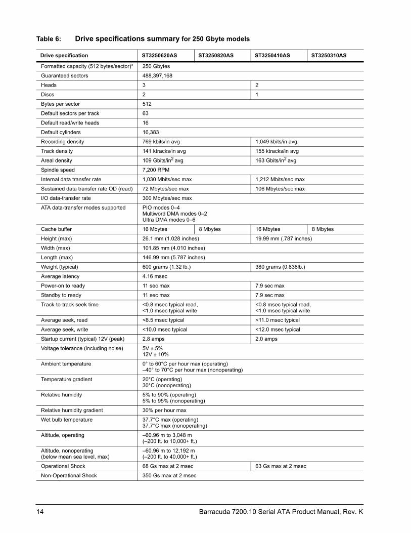
Table 6: Drive specifications summary for 250 Gbyte models
Drive specification ST3250620AS ST3250820AS ST3250410AS ST3250310AS
Formatted capacity (512 bytes/sector)* 250 Gbytes
Guaranteed sectors 488,397,168
Heads 3 2
Discs 2 1
Bytes per sector 512
Default sectors per track 63
Default read/write heads 16
Default cylinders 16,383
Recording density 769 kbits/in avg 1,049 kbits/in avg
Track density 141 ktracks/in avg 155 ktracks/in avg
Areal density 109 Gbits/in2 avg 163 Gbits/in2 avg
Spindle speed 7,200 RPM
Internal data transfer rate 1,030 Mbits/sec max 1,212 Mbits/sec max
Sustained data transfer rate OD (read) 72 Mbytes/sec max 106 Mbytes/sec max
I/O data-transfer rate 300 Mbytes/sec max
ATA data-transfer modes supported PIO modes 0–4 Multiword DMA modes 0–2 Ultra DMA modes 0–6
Cache buffer 16 Mbytes 8 Mbytes 16 Mbytes 8 Mbytes
Height (max) 26.1 mm (1.028 inches) 19.99 mm (.787 inches)
Width (max) 101.85 mm (4.010 inches)
Length (max) 146.99 mm (5.787 inches)
Weight (typical) 600 grams (1.32 lb.) 380 grams (0.838lb.)
Average latency 4.16 msec
Power-on to ready 11 sec max 7.9 sec max
Standby to ready 11 sec max 7.9 sec max
Track-to-track seek time <0.8 msec typical read, <1.0 msec typical write
<0.8 msec typical read, <1.0 msec typical write
Average seek, read <8.5 msec typical <11.0 msec typical
Average seek, write <10.0 msec typical <12.0 msec typical
Startup current (typical) 12V (peak) 2.8 amps 2.0 amps
Voltage tolerance (including noise) 5V ± 5% 12V ± 10%
Ambient temperature 0° to 60°C per hour max (operating) –40° to 70°C per hour max (nonoperating)
Temperature gradient 20°C (operating) 30°C (nonoperating)
Relative humidity 5% to 90% (operating) 5% to 95% (nonoperating)
Relative humidity gradient 30% per hour max
Wet bulb temperature 37.7°C max (operating) 37.7°C max (nonoperating)
Altitude, operating –60.96 m to 3,048 m (–200 ft. to 10,000+ ft.)
Altitude, nonoperating (below mean sea level, max)
–60.96 m to 12,192 m (–200 ft. to 40,000+ ft.)
Operational Shock 68 Gs max at 2 msec 63 Gs max at 2 msec
Non-Operational Shock 350 Gs max at 2 msec
Barracuda 7200.10 Serial ATA Product Manual, Rev. K 15
*One Gbyte equals one billion bytes when referring to hard drive capacity. Accessible capacity may vary depending on operating environment and formatting.
**During periods of drive idle, some offline activity may occur according to the S.M.A.R.T. specification, which may increase acoustic and power to operational levels.
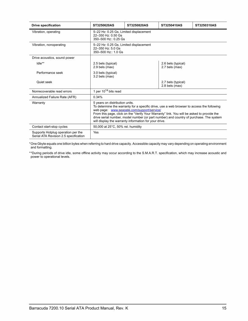
Vibration, operating 5–22 Hz: 0.25 Gs, Limited displacement 22–350 Hz: 0.50 Gs 350–500 Hz:: 0.25 Gs
Vibration, nonoperating 5–22 Hz: 0.25 Gs, Limited displacement 22–350 Hz: 5.0 Gs 350–500 Hz:: 1.0 Gs
Drive acoustics, sound power
Idle** 2.5 bels (typical) 2.9 bels (max)
2.6 bels (typical) 2.7 bels (max)
Performance seek 3.0 bels (typical) 3.2 bels (max)
Quiet seek 2.7 bels (typical) 2.8 bels (max)
Nonrecoverable read errors 1 per 1014 bits read
Annualized Failure Rate (AFR) 0.34%
Warranty 5 years on distribution units.To determine the warranty for a specific drive, use a web browser to access the following web page: www.seagate.com/support/service/From this page, click on the “Verify Your Warranty” link. You will be asked to provide the drive serial number, model number (or part number) and country of purchase. The system will display the warranty information for your drive.
Contact start-stop cycles 50,000 at 25°C, 50% rel. humidity
Supports Hotplug operation per the Serial ATA Revision 2.5 specification
Yes
Drive specification ST3250620AS ST3250820AS ST3250410AS ST3250310AS
16 Barracuda 7200.10 Serial ATA Product Manual, Rev. K
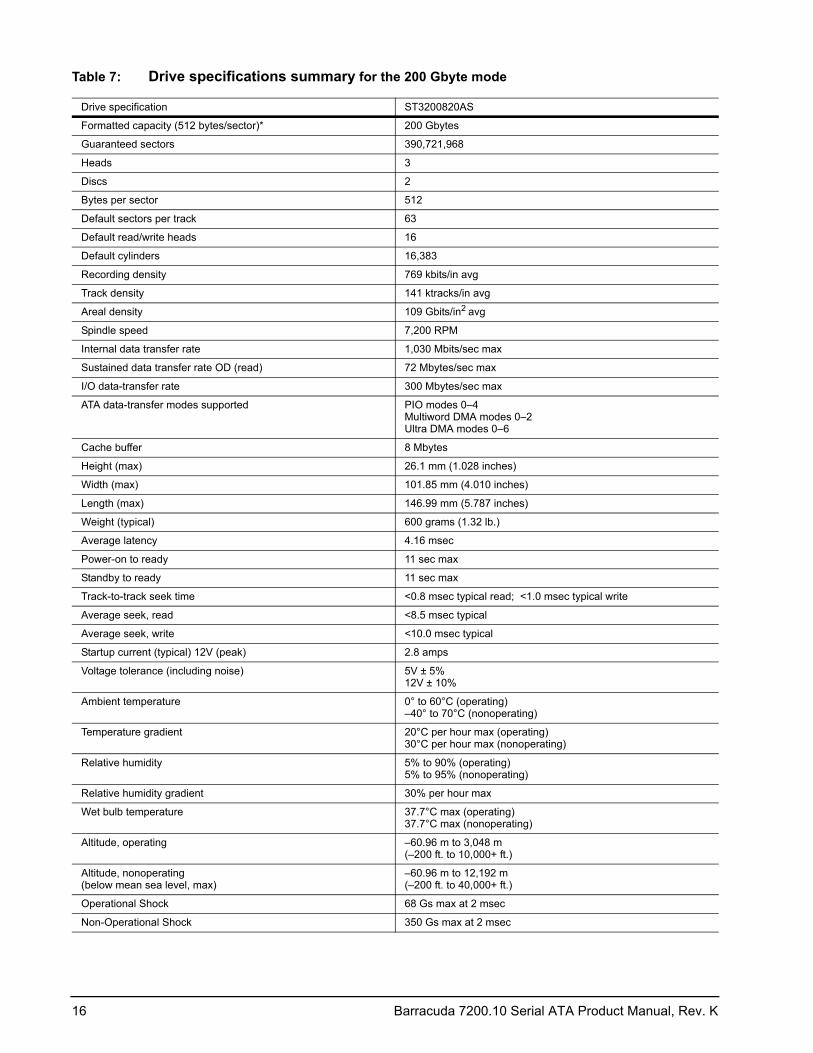
Table 7: Drive specifications summary for the 200 Gbyte mode
Drive specification ST3200820AS
Formatted capacity (512 bytes/sector)* 200 Gbytes
Guaranteed sectors 390,721,968
Heads 3
Discs 2
Bytes per sector 512
Default sectors per track 63
Default read/write heads 16
Default cylinders 16,383
Recording density 769 kbits/in avg
Track density 141 ktracks/in avg
Areal density 109 Gbits/in2 avg
Spindle speed 7,200 RPM
Internal data transfer rate 1,030 Mbits/sec max
Sustained data transfer rate OD (read) 72 Mbytes/sec max
I/O data-transfer rate 300 Mbytes/sec max
ATA data-transfer modes supported PIO modes 0–4 Multiword DMA modes 0–2 Ultra DMA modes 0–6
Cache buffer 8 Mbytes
Height (max) 26.1 mm (1.028 inches)
Width (max) 101.85 mm (4.010 inches)
Length (max) 146.99 mm (5.787 inches)
Weight (typical) 600 grams (1.32 lb.)
Average latency 4.16 msec
Power-on to ready 11 sec max
Standby to ready 11 sec max
Track-to-track seek time <0.8 msec typical read; <1.0 msec typical write
Average seek, read <8.5 msec typical
Average seek, write <10.0 msec typical
Startup current (typical) 12V (peak) 2.8 amps
Voltage tolerance (including noise) 5V ± 5% 12V ± 10%
Ambient temperature 0° to 60°C (operating) –40° to 70°C (nonoperating)
Temperature gradient 20°C per hour max (operating) 30°C per hour max (nonoperating)
Relative humidity 5% to 90% (operating) 5% to 95% (nonoperating)
Relative humidity gradient 30% per hour max
Wet bulb temperature 37.7°C max (operating) 37.7°C max (nonoperating)
Altitude, operating –60.96 m to 3,048 m (–200 ft. to 10,000+ ft.)
Altitude, nonoperating (below mean sea level, max)
–60.96 m to 12,192 m (–200 ft. to 40,000+ ft.)
Operational Shock 68 Gs max at 2 msec
Non-Operational Shock 350 Gs max at 2 msec
Barracuda 7200.10 Serial ATA Product Manual, Rev. K 17
*One Gbyte equals one billion bytes when referring to hard drive capacity. Accessible capacity may vary depending on operating environment and formatting.
**During periods of drive idle, some offline activity may occur according to the S.M.A.R.T. specification, which may increase acoustic and power to operational levels.
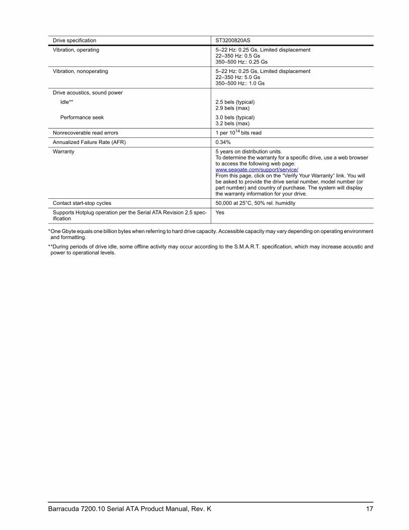
Vibration, operating 5–22 Hz: 0.25 Gs, Limited displacement 22–350 Hz: 0.5 Gs 350–500 Hz:: 0.25 Gs
Vibration, nonoperating 5–22 Hz: 0.25 Gs, Limited displacement 22–350 Hz: 5.0 Gs 350–500 Hz:: 1.0 Gs
Drive acoustics, sound power
Idle** 2.5 bels (typical) 2.9 bels (max)
Performance seek 3.0 bels (typical) 3.2 bels (max)
Nonrecoverable read errors 1 per 1014 bits read
Annualized Failure Rate (AFR) 0.34%
Warranty 5 years on distribution units.To determine the warranty for a specific drive, use a web browser to access the following web page: www.seagate.com/support/service/From this page, click on the “Verify Your Warranty” link. You will be asked to provide the drive serial number, model number (or part number) and country of purchase. The system will display the warranty information for your drive.
Contact start-stop cycles 50,000 at 25°C, 50% rel. humidity
Supports Hotplug operation per the Serial ATA Revision 2.5 spec-ification
Yes
Drive specification ST3200820AS
18 Barracuda 7200.10 Serial ATA Product Manual, Rev. K
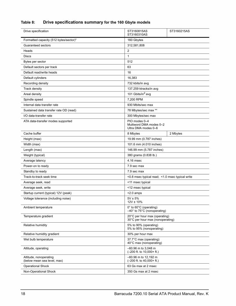
Table 8: Drive specifications summary for the 160 Gbyte models
Drive specification ST3160815AS ST3160310AS
ST3160215AS
Formatted capacity (512 bytes/sector)* 160 Gbytes
Guaranteed sectors 312,581,808
Heads 2
Discs 1
Bytes per sector 512
Default sectors per track 63
Default read/write heads 16
Default cylinders 16,383
Recording density 732 kbits/in avg
Track density 137.259 ktracks/in avg
Areal density 101 Gbits/in2 avg
Spindle speed 7,200 RPM
Internal data transfer rate 930 Mbits/sec max
Sustained data transfer rate OD (read) 78 Mbytes/sec max **
I/O data-transfer rate 300 Mbytes/sec max
ATA data-transfer modes supported PIO modes 0–4 Multiword DMA modes 0–2 Ultra DMA modes 0–6
Cache buffer 8 Mbytes 2 Mbytes
Height (max) 19.99 mm (0.787 inches)
Width (max) 101.6 mm (4.010 inches)
Length (max) 146.99 mm (5.787 inches)
Weight (typical) 380 grams (0.838 lb.)
Average latency 4.16 msec
Power-on to ready 7.9 sec max
Standby to ready 7.9 sec max
Track-to-track seek time <0.8 msec typical read; <1.0 msec typical write
Average seek, read <11 msec typical
Average seek, write <12 msec typical
Startup current (typical) 12V (peak) <2.0 amps
Voltage tolerance (including noise) 5V ± 5% 12V ± 10%
Ambient temperature 0° to 60°C (operating) –40° to 75°C (nonoperating)
Temperature gradient 20°C per hour max (operating) 30°C per hour max (nonoperating)
Relative humidity 5% to 90% (operating) 5% to 95% (nonoperating)
Relative humidity gradient 30% per hour max
Wet bulb temperature 37.7°C max (operating) 40°C max (nonoperating)
Altitude, operating –60.96 m to 3,048 m (–200 ft. to 10,000+ ft.)
Altitude, nonoperating (below mean sea level, max)
–60.96 m to 12,192 m (–200 ft. to 40,000+ ft.)
Operational Shock 63 Gs max at 2 msec
Non-Operational Shock 350 Gs max at 2 msec
Barracuda 7200.10 Serial ATA Product Manual, Rev. K 19
*One Gbyte equals one billion bytes when referring to hard drive capacity. Accessible capacity may vary depending on operating environment and formatting.
** 7200.10 family product achieved higher sustained data rate over same 7200.9 family capacity points using identical measurement methodology.
*** During periods of drive idle, some offline activity may occur according to the S.M.A.R.T. specification, which may increase acoustic and power to operational levels.
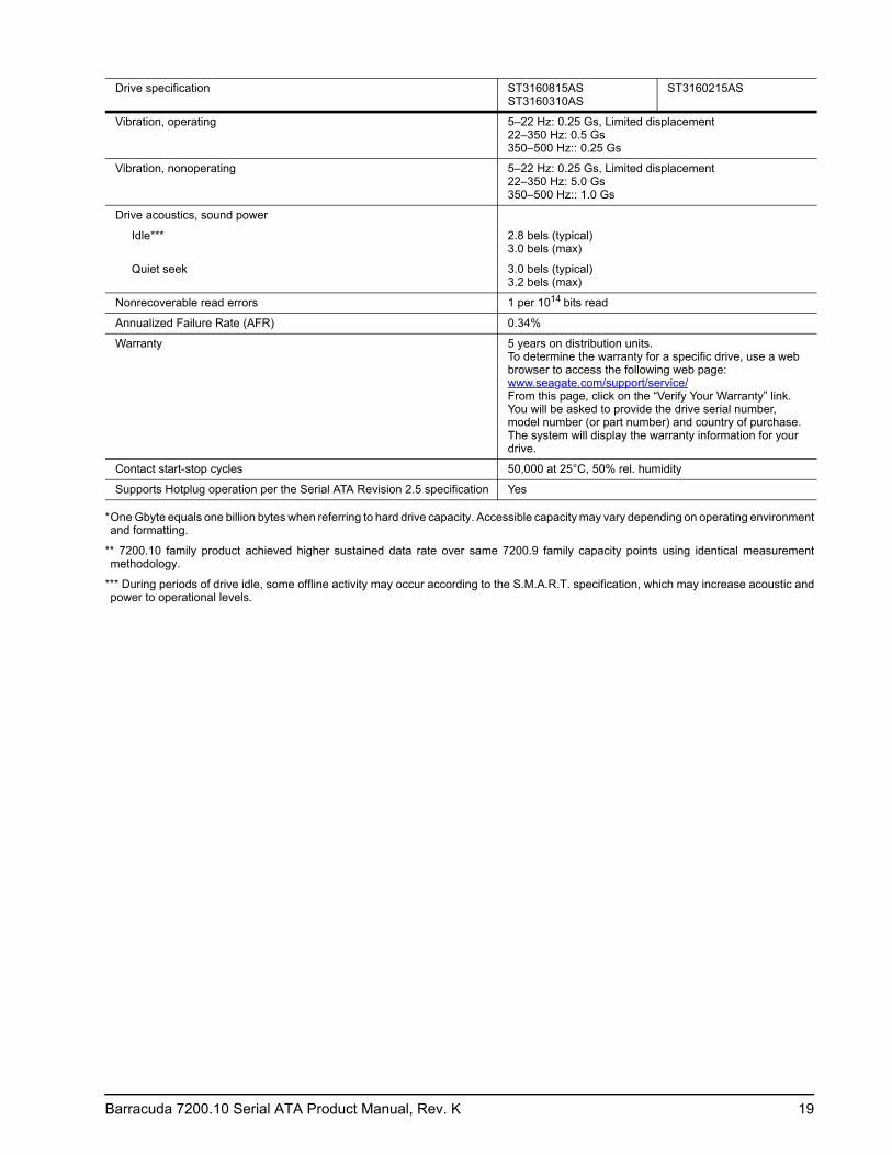
Vibration, operating 5–22 Hz: 0.25 Gs, Limited displacement 22–350 Hz: 0.5 Gs 350–500 Hz:: 0.25 Gs
Vibration, nonoperating 5–22 Hz: 0.25 Gs, Limited displacement 22–350 Hz: 5.0 Gs 350–500 Hz:: 1.0 Gs
Drive acoustics, sound power
Idle*** 2.8 bels (typical) 3.0 bels (max)
Quiet seek 3.0 bels (typical) 3.2 bels (max)
Nonrecoverable read errors 1 per 1014 bits read
Annualized Failure Rate (AFR) 0.34%
Warranty 5 years on distribution units.To determine the warranty for a specific drive, use a web browser to access the following web page: www.seagate.com/support/service/From this page, click on the “Verify Your Warranty” link. You will be asked to provide the drive serial number, model number (or part number) and country of purchase. The system will display the warranty information for your drive.
Contact start-stop cycles 50,000 at 25°C, 50% rel. humidity
Supports Hotplug operation per the Serial ATA Revision 2.5 specification Yes
Drive specification ST3160815AS ST3160310AS
ST3160215AS

20 Barracuda 7200.10 Serial ATA Product Manual, Rev. K
Table 9: Drive specifications summary for the 120 Gbyte models
Drive specification ST3120815AS ST3120215AS
Formatted capacity (512 bytes/sector)* 120 Gbytes
Guaranteed sectors 234,441,648
Heads 2
Discs 1
Bytes per sector 512
Default sectors per track 63
Default read/write heads 16
Default cylinders 16,383
Recording density 732 kbits/in avg
Track density 137.259 ktracks/in avg
Areal density 101 Gbits/in2 avg
Spindle speed 7,200 RPM
Internal data transfer rate 930 Mbits/sec max
Sustained data transfer rate OD (read) 78 Mbytes/sec max **
I/O data-transfer rate 300 Mbytes/sec max
ATA data-transfer modes supported PIO modes 0–4 Multiword DMA modes 0–2 Ultra DMA modes 0–6
Cache buffer 8 Mbytes 2 Mbytes
Height (max) 19.99 mm (0.787 inches)
Width (max) 101.85 mm (4.010 inches)
Length (max) 146.99 mm (5.787 inches)
Weight (typical) 380 grams (0.838 lb.)
Average latency 4.16 msec
Power-on to ready 7.9 sec max
Standby to ready 7.9 sec max
Track-to-track seek time <0.8 msec typical read; <1.0 msec typical write
Average seek, read <11 msec typical
Average seek, write <12 msec typical
Startup current (typical) 12V (peak) <2.0 amps
Voltage tolerance (including noise) 5V ± 5% 12V ± 10%
Ambient temperature 0° to 60°C (operating) –40° to 75°C (nonoperating)
Temperature gradient 20°C per hour max (operating) 30°C per hour max (nonoperating)
Relative humidity 5% to 90% (operating) 5% to 95% (nonoperating)
Relative humidity gradient 30% per hour max
Wet bulb temperature 37.7°C max (operating) 40°C max (nonoperating)
Altitude, operating –60.96 m to 3,048 m (–200 ft. to 10,000+ ft.)
Altitude, nonoperating (below mean sea level, max)
–60.96 m to 12,192 m (–200 ft. to 40,000+ ft.)
Operational Shock 63 Gs max at 2 msec
Non-Operational Shock 350 Gs max at 2 msec

Barracuda 7200.10 Serial ATA Product Manual, Rev. K 21
*One Gbyte equals one billion bytes when referring to hard drive capacity. Accessible capacity may vary depending on operating environment and formatting.
** 7200.10 family product achieved higher sustained data rate over same 7200.9 family capacity points using identical measurement methodology.
*** During periods of drive idle, some offline activity may occur according to the S.M.A.R.T. specification, which may increase acoustic and power to operational levels.
Vibration, operating 5–22 Hz: 0.25 Gs, Limited displacement 22–350 Hz: 0.5 Gs 350–500 Hz:: 0.25 Gs
Vibration, nonoperating 5–22 Hz: 0.25 Gs, Limited displacement 22–350 Hz: 5.0 Gs 350–500 Hz:: 1.0 Gs
Drive acoustics, sound power
Idle*** 2.8 bels (typical) 3.0 bels (max)
Quiet seek 3.0 bels (typical) 3.2 bels (max)
Nonrecoverable read errors 1 per 1014 bits read
Annualized Failure Rate (AFR) 0.34%
Warranty 5 years on distribution units.To determine the warranty for a specific drive, use a web browser to access the following web page: www.seagate.com/support/service/From this page, click on the “Verify Your Warranty” link. You will be asked to provide the drive serial number, model number (or part number) and country of purchase. The system will display the warranty information for your drive.
Contact start-stop cycles 50,000 at 25°C, 50% rel. humidity
Supports Hotplug operation per the Serial ATA Revision 2.5 specification Yes
Drive specification ST3120815AS ST3120215AS
22 Barracuda 7200.10 Serial ATA Product Manual, Rev. K
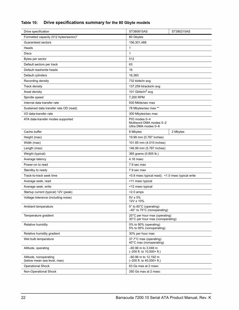
Table 10: Drive specifications summary for the 80 Gbyte models
Drive specification ST380815AS ST380215AS
Formatted capacity (512 bytes/sector)* 80 Gbytes
Guaranteed sectors 156,301,488
Heads 1
Discs 1
Bytes per sector 512
Default sectors per track 63
Default read/write heads 16
Default cylinders 16,383
Recording density 732 kbits/in avg
Track density 137.259 ktracks/in avg
Areal density 101 Gbits/in2 avg
Spindle speed 7,200 RPM
Internal data transfer rate 930 Mbits/sec max
Sustained data transfer rate OD (read) 78 Mbytes/sec max **
I/O data-transfer rate 300 Mbytes/sec max
ATA data-transfer modes supported PIO modes 0–4 Multiword DMA modes 0–2 Ultra DMA modes 0–6
Cache buffer 8 Mbytes 2 Mbytes
Height (max) 19.99 mm (0.787 inches)
Width (max) 101.85 mm (4.010 inches)
Length (max) 146.99 mm (5.787 inches)
Weight (typical) 365 grams (0.805 lb.)
Average latency 4.16 msec
Power-on to read 7.9 sec max
Standby to ready 7.9 sec max
Track-to-track seek time <0.8 msec typical read); <1.0 msec typical write
Average seek, read <11 msec typical
Average seek, write <12 msec typical
Startup current (typical) 12V (peak) <2.0 amps
Voltage tolerance (including noise) 5V ± 5% 12V ± 10%
Ambient temperature 0° to 60°C (operating) –40° to 75°C (nonoperating)
Temperature gradient 20°C per hour max (operating) 30°C per hour max (nonoperating)
Relative humidity 5% to 90% (operating) 5% to 95% (nonoperating)
Relative humidity gradient 30% per hour max
Wet bulb temperature 37.7°C max (operating) 40°C max (nonoperating)
Altitude, operating –60.96 m to 3,048 m (–200 ft. to 10,000+ ft.)
Altitude, nonoperating (below mean sea level, max)
–60.96 m to 12,192 m (–200 ft. to 40,000+ ft.)
Operational Shock 63 Gs max at 2 msec
Non-Operational Shock 350 Gs max at 2 msec

Barracuda 7200.10 Serial ATA Product Manual, Rev. K 23
*One Gbyte equals one billion bytes when referring to hard drive capacity. Accessible capacity may vary depending on operating environment and formatting.
** 7200.10 family product achieved higher sustained data rate over same 7200.9 family capacity points using identical measurement methodology.
*** During periods of drive idle, some offline activity may occur according to the S.M.A.R.T. specification, which may increase acoustic and power to operational levels.
Vibration, operating 5–22 Hz: 0.25 Gs, Limited displacement 22–350 Hz: 0.5 Gs 350–500 Hz:: 0.25 Gs
Vibration, nonoperating 5–22 Hz: 0.25 Gs, Limited displacement 22–350 Hz: 5.0 Gs 350–500 Hz:: 1.0 Gs
Drive acoustics, sound power
Idle*** 2.8 bels (typical) 3.0 bels (max)
Quiet seek 3.0 bels (typical) 3.2 bels (max)
Nonrecoverable read errors 1 per 1014 bits read
Annualized Failure Rate (AFR) 0.34%
Warranty 5 years on distribution units.To determine the warranty for a specific drive, use a web browser to access the following web page: www.seagate.com/support/service/From this page, click on the “Verify Your Warranty” link. You will be asked to provide the drive serial number, model number (or part number) and country of purchase. The system will display the warranty information for your drive.
Contact start-stop cycles 50,000 at 25°C, 50% rel. humidity
Supports Hotplug operation per the Serial ATA Revision 2.5 specification Yes
Drive specification ST380815AS ST380215AS

24 Barracuda 7200.10 Serial ATA Product Manual, Rev. K
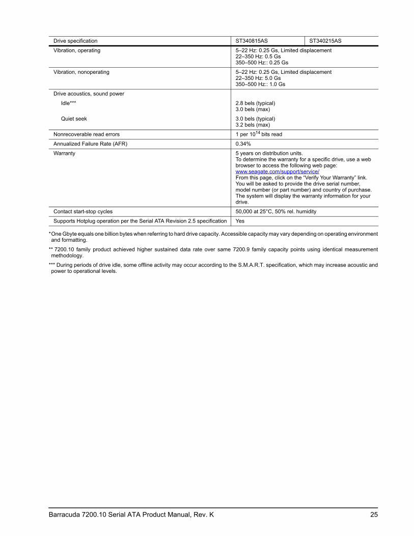
Table 11: Drive specifications summary for the 40 Gbyte models
Drive specification ST340815AS ST340215AS
Formatted capacity (512 bytes/sector)* 40 Gbytes
Guaranteed sectors 78,165,360
Heads 1
Discs 1
Bytes per sector 512
Default sectors per track 63
Default read/write heads 16
Default cylinders 16,383
Recording density 732 kbits/in avg
Track density 137.259 ktracks/in avg
Areal density 101 Gbits/in2 avg
Spindle speed 7,200 RPM
Internal data transfer rate 930 Mbits/sec max
Sustained data transfer rate OD (read) 78 Mbytes/sec max **
I/O data-transfer rate 300 Mbytes/sec max
ATA data-transfer modes supported PIO modes 0–4 Multiword DMA modes 0–2 Ultra DMA modes 0–6
Cache buffer 8 Mbytes 2 Mbytes
Height (max) 19.99 mm (0.787 inches)
Width (max) 101.85 mm (4.010 inches)
Length (max) 146.99 mm (5.787 inches)
Weight (typical) 365 grams (0.805 lb.)
Average latency 4.16 msec
Power-on to ready 7.9 sec max
Standby to ready 7.9 sec max
Track-to-track seek time <0.8 msec typical read; <1.0 msec typical write
Average seek, read <11 msec typical
Average seek, write <12 msec typical
Startup current (typical) 12V (peak) <2.0 amps
Voltage tolerance (including noise) 5V ± 5% 12V ± 10%
Ambient temperature 0° to 60°C (operating) –40° to 75°C (nonoperating)
Temperature gradient 20°C per hour max (operating) 30°C per hour max (nonoperating)
Relative humidity 5% to 90% (operating) 5% to 95% (nonoperating)
Relative humidity gradient 30% per hour max
Wet bulb temperature 37.7°C max (operating) 40°C max (nonoperating)
Altitude, operating –60.96 m to 3,048 m (–200 ft. to 10,000+ ft.)
Altitude, nonoperating (below mean sea level, max)
–60.96 m to 12,192 m (–200 ft. to 40,000+ ft.)
Operational Shock 63 Gs max at 2 msec
Non-Operational Shock 350 Gs max at 2 msec
Barracuda 7200.10 Serial ATA Product Manual, Rev. K 25
*One Gbyte equals one billion bytes when referring to hard drive capacity. Accessible capacity may vary depending on operating environment and formatting.
** 7200.10 family product achieved higher sustained data rate over same 7200.9 family capacity points using identical measurement methodology.
*** During periods of drive idle, some offline activity may occur according to the S.M.A.R.T. specification, which may increase acoustic and power to operational levels.
Vibration, operating 5–22 Hz: 0.25 Gs, Limited displacement 22–350 Hz: 0.5 Gs 350–500 Hz:: 0.25 Gs
Vibration, nonoperating 5–22 Hz: 0.25 Gs, Limited displacement 22–350 Hz: 5.0 Gs 350–500 Hz:: 1.0 Gs
Drive acoustics, sound power
Idle*** 2.8 bels (typical) 3.0 bels (max)
Quiet seek 3.0 bels (typical) 3.2 bels (max)
Nonrecoverable read errors 1 per 1014 bits read
Annualized Failure Rate (AFR) 0.34%
Warranty 5 years on distribution units.To determine the warranty for a specific drive, use a web browser to access the following web page: www.seagate.com/support/service/From this page, click on the “Verify Your Warranty” link. You will be asked to provide the drive serial number, model number (or part number) and country of purchase. The system will display the warranty information for your drive.
Contact start-stop cycles 50,000 at 25°C, 50% rel. humidity
Supports Hotplug operation per the Serial ATA Revision 2.5 specification Yes
Drive specification ST340815AS ST340215AS
26 Barracuda 7200.10 Serial ATA Product Manual, Rev. K
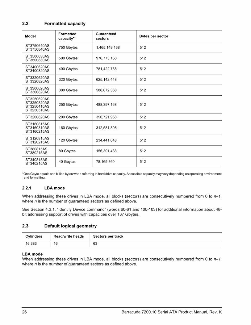
2.2 Formatted capacity
*One Gbyte equals one billion bytes when referring to hard drive capacity. Accessible capacity may vary depending on operating environment and formatting.
2.2.1 LBA mode
When addressing these drives in LBA mode, all blocks (sectors) are consecutively numbered from 0 to n–1, where n is the number of guaranteed sectors as defined above.
See Section 4.3.1, "Identify Device command" (words 60-61 and 100-103) for additional information about 48-bit addressing support of drives with capacities over 137 Gbytes.
2.3 Default logical geometry
LBA mode When addressing these drives in LBA mode, all blocks (sectors) are consecutively numbered from 0 to n–1, where n is the number of guaranteed sectors as defined above.
Model Formatted capacity*
Guaranteed sectors Bytes per sector
ST3750640AS ST3750840AS 750 Gbytes 1,465,149,168 512
ST3500630AS ST3500830AS 500 Gbytes 976,773,168 512
ST3400620AS ST3400820AS 400 Gbytes 781,422,768 512
ST3320620AS ST3320820AS 320 Gbytes 625,142,448 512
ST3300620AS ST3300820AS 300 Gbytes 586,072,368 512
ST3250620AS ST3250820AS ST3250410AS ST3250310AS
250 Gbytes 488,397,168 512
ST3200820AS 200 Gbytes 390,721,968 512
ST3160815AS ST3160310AS ST3160215AS
160 Gbytes 312,581,808 512
ST3120815AS ST3120215AS 120 Gbytes 234,441,648 512
ST380815AS ST380215AS 80 Gbytes 156,301,488 512
ST340815AS ST340215AS 40 Gbytes 78,165,360 512
Cylinders Read/write heads Sectors per track
16,383 16 63
Barracuda 7200.10 Serial ATA Product Manual, Rev. K 27
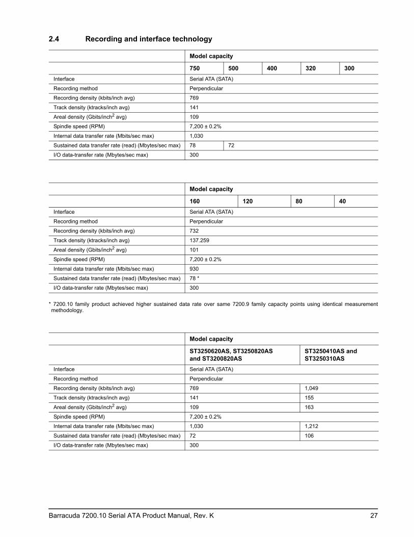
2.4 Recording and interface technology
* 7200.10 family product achieved higher sustained data rate over same 7200.9 family capacity points using identical measurement methodology.
Model capacity
750 500 400 320 300Interface Serial ATA (SATA)
Recording method Perpendicular
Recording density (kbits/inch avg) 769
Track density (ktracks/inch avg) 141
Areal density (Gbits/inch2 avg) 109
Spindle speed (RPM) 7,200 ± 0.2%
Internal data transfer rate (Mbits/sec max) 1,030
Sustained data transfer rate (read) (Mbytes/sec max) 78 72
I/O data-transfer rate (Mbytes/sec max) 300
Model capacity
160 120 80 40Interface Serial ATA (SATA)
Recording method Perpendicular
Recording density (kbits/inch avg) 732
Track density (ktracks/inch avg) 137.259
Areal density (Gbits/inch2 avg) 101
Spindle speed (RPM) 7,200 ± 0.2%
Internal data transfer rate (Mbits/sec max) 930
Sustained data transfer rate (read) (Mbytes/sec max) 78 *
I/O data-transfer rate (Mbytes/sec max) 300
Model capacity
ST3250620AS, ST3250820AS and ST3200820AS
ST3250410AS and ST3250310AS
Interface Serial ATA (SATA)
Recording method Perpendicular
Recording density (kbits/inch avg) 769 1,049
Track density (ktracks/inch avg) 141 155
Areal density (Gbits/inch2 avg) 109 163
Spindle speed (RPM) 7,200 ± 0.2%
Internal data transfer rate (Mbits/sec max) 1,030 1,212
Sustained data transfer rate (read) (Mbytes/sec max) 72 106
I/O data-transfer rate (Mbytes/sec max) 300
28 Barracuda 7200.10 Serial ATA Product Manual, Rev. K
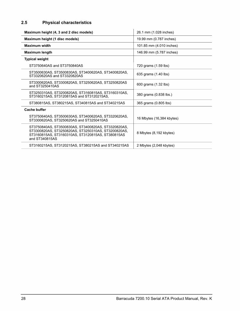
2.5 Physical characteristics
Maximum height (4, 3 and 2 disc models) 26.1 mm (1.028 inches)
Maximum height (1 disc models) 19.99 mm (0.787 inches)
Maximum width 101.85 mm (4.010 inches)
Maximum length 146.99 mm (5.787 inches)
Typical weight
ST3750640AS and ST3750840AS 720 grams (1.59 lbs)
ST3500630AS, ST3500830AS, ST3400620AS, ST3400820AS, ST3320620AS and ST3320820AS 635 grams (1.40 lbs)
ST3300620AS, ST3300820AS, ST3250620AS, ST3250820AS and ST3250410AS 600 grams (1.32 lbs)
ST3250310AS, ST3200820AS, ST3160815AS, ST3160310AS, ST3160215AS, ST3120815AS and ST3120215AS, 380 grams (0.838 lbs.)
ST380815AS, ST380215AS, ST340815AS and ST340215AS 365 grams (0.805 lbs)
Cache buffer
ST3750640AS, ST3500630AS, ST3400620AS, ST3320620AS, ST3300620AS, ST3250620AS and ST3250410AS 16 Mbytes (16,384 kbytes)
ST3750840AS, ST3500830AS, ST3400820AS, ST3320820AS, ST3300820AS, ST3250820AS, ST3250310AS, ST3200820AS, ST3160815AS, ST3160310AS, ST3120815AS, ST380815AS and ST340815AS
8 Mbytes (8,192 kbytes)
ST3160215AS, ST3120215AS, ST380215AS and ST340215AS 2 Mbytes (2,048 kbytes)
Barracuda 7200.10 Serial ATA Product Manual, Rev. K 29
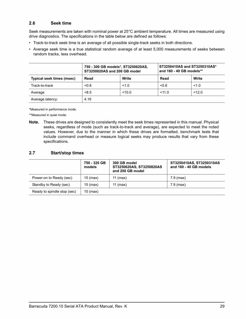
2.6 Seek time
Seek measurements are taken with nominal power at 25°C ambient temperature. All times are measured using drive diagnostics. The specifications in the table below are defined as follows:• Track-to-track seek time is an average of all possible single-track seeks in both directions.• Average seek time is a true statistical random average of at least 5,000 measurements of seeks between
random tracks, less overhead.
*Measured in performance mode.
**Measured in quiet mode.
Note. These drives are designed to consistently meet the seek times represented in this manual. Physical seeks, regardless of mode (such as track-to-track and average), are expected to meet the noted values. However, due to the manner in which these drives are formatted, benchmark tests that include command overhead or measure logical seeks may produce results that vary from these specifications.
2.7 Start/stop times
750 - 300 GB models*, ST3250620AS, ST3250820AS and 200 GB model
ST3250410AS and ST3250310AS* and 160 - 40 GB models**
Typical seek times (msec) Read Write Read Write
Track-to-track <0.8 <1.0 <0.8 <1.0
Average <8.5 <10.0 <11.0 <12.0
Average latency: 4.16
750 - 320 GB models
300 GB model ST3250620AS, ST3250820AS and 200 GB model
ST3250410AS, ST3250310AS and 160 - 40 GB models
Power-on to Ready (sec) 15 (max) 11 (max) 7.9 (max)
Standby to Ready (sec) 15 (max) 11 (max) 7.9 (max)
Ready to spindle stop (sec) 10 (max)
30 Barracuda 7200.10 Serial ATA Product Manual, Rev. K
2.8 Power specifications
The drive receives DC power (+5V or +12V) through a native SATA power connector. See Figure 4 on page 42.
2.8.1 Power consumption
Power requirements for the drives are listed in the table on page 9. Typical power measurements are based on an average of drives tested, under nominal conditions, using 5.0V and 12.0V input voltage at 25°C ambient temperature.• Spinup power
Spinup power is measured from the time of power-on to the time that the drive spindle reaches operating speed.
• Seek modeDuring seek mode, the read/write actuator arm moves toward a specific position on the disc surface and does not execute a read or write operation. Servo electronics are active. Seek mode power represents the worst-case power consumption, using only random seeks with read or write latency time. This mode is not typical and is provided for worst-case information.
• Read/write power and currentRead/write power is measured with the heads on track, based on a 16-sector write followed by a 32-msec delay, then a 16-sector read followed by a 32-msec delay.
• Operating power and current Operating power is measured using 40 percent random seeks, 40 percent read/write mode (1 write for each 10 reads) and 20 percent drive idle mode.
• Idle mode powerIdle mode power is measured with the drive up to speed, with servo electronics active and with the heads in a random track location.
• Standby modeDuring Standby mode, the drive accepts commands, but the drive is not spinning, and the servo and read/write electronics are in power-down mode.
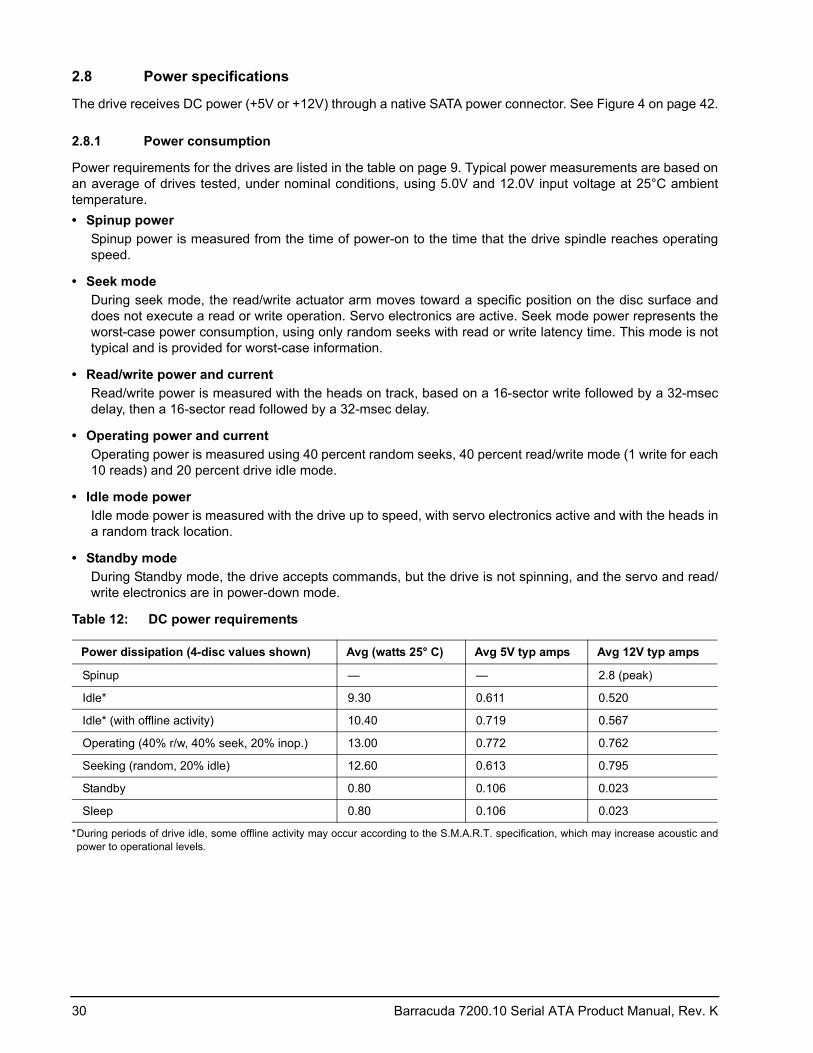
Table 12: DC power requirements
*During periods of drive idle, some offline activity may occur according to the S.M.A.R.T. specification, which may increase acoustic and power to operational levels.
Power dissipation (4-disc values shown) Avg (watts 25° C) Avg 5V typ amps Avg 12V typ amps
Spinup — — 2.8 (peak)
Idle* 9.30 0.611 0.520
Idle* (with offline activity) 10.40 0.719 0.567
Operating (40% r/w, 40% seek, 20% inop.) 13.00 0.772 0.762
Seeking (random, 20% idle) 12.60 0.613 0.795
Standby 0.80 0.106 0.023
Sleep 0.80 0.106 0.023
Barracuda 7200.10 Serial ATA Product Manual, Rev. K 31
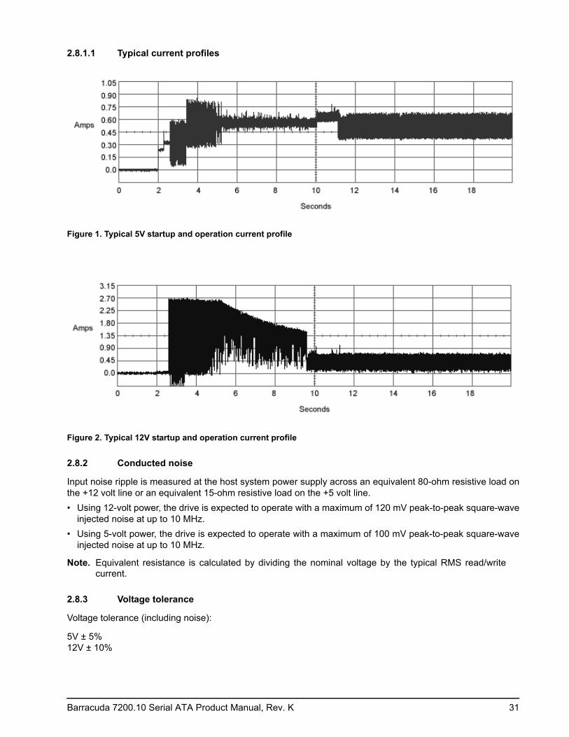
2.8.1.1 Typical current profiles
Figure 1. Typical 5V startup and operation current profile
Figure 2. Typical 12V startup and operation current profile
2.8.2 Conducted noise
Input noise ripple is measured at the host system power supply across an equivalent 80-ohm resistive load on the +12 volt line or an equivalent 15-ohm resistive load on the +5 volt line.• Using 12-volt power, the drive is expected to operate with a maximum of 120 mV peak-to-peak square-wave
injected noise at up to 10 MHz.• Using 5-volt power, the drive is expected to operate with a maximum of 100 mV peak-to-peak square-wave
injected noise at up to 10 MHz.
Note. Equivalent resistance is calculated by dividing the nominal voltage by the typical RMS read/write current.
2.8.3 Voltage tolerance
Voltage tolerance (including noise):
5V ± 5% 12V ± 10%
32 Barracuda 7200.10 Serial ATA Product Manual, Rev. K
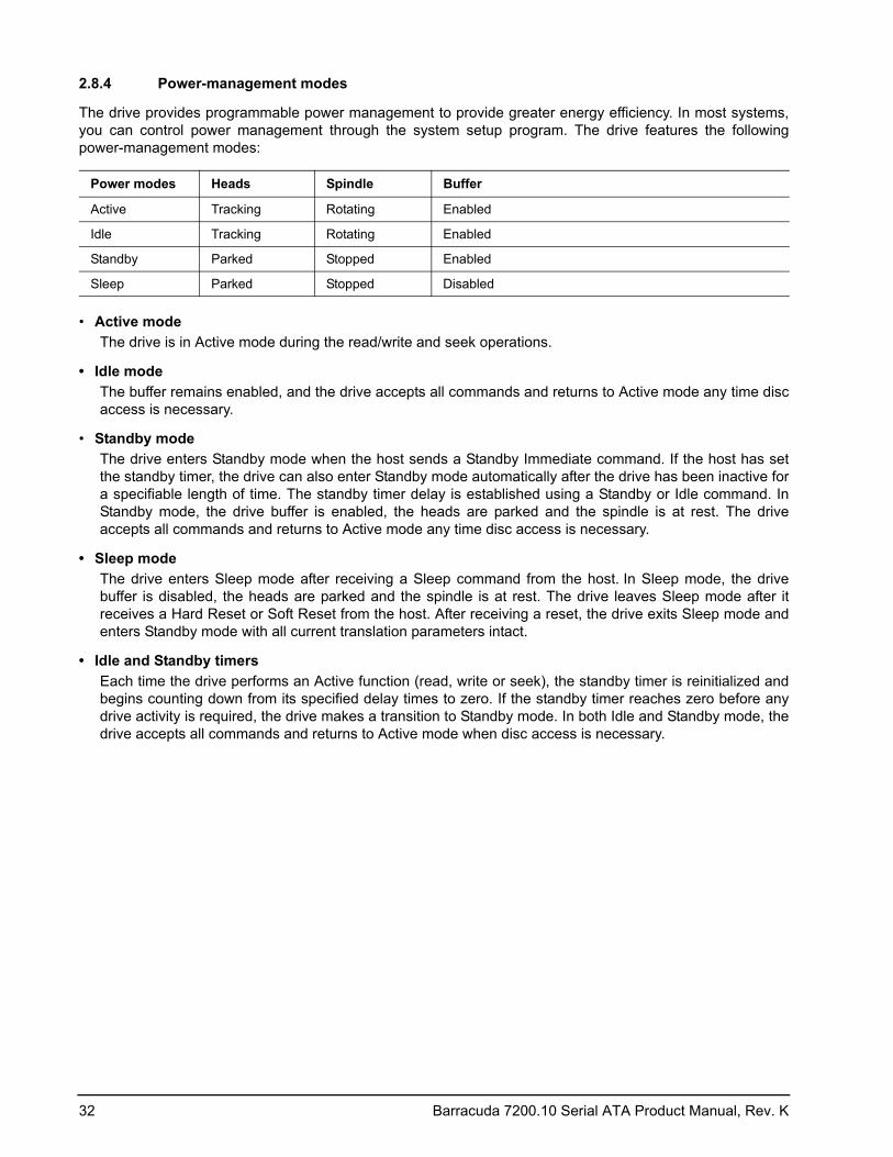
2.8.4 Power-management modes
The drive provides programmable power management to provide greater energy efficiency. In most systems, you can control power management through the system setup program. The drive features the following power-management modes:
• Active mode The drive is in Active mode during the read/write and seek operations.
• Idle modeThe buffer remains enabled, and the drive accepts all commands and returns to Active mode any time disc access is necessary.
• Standby mode The drive enters Standby mode when the host sends a Standby Immediate command. If the host has set the standby timer, the drive can also enter Standby mode automatically after the drive has been inactive for a specifiable length of time. The standby timer delay is established using a Standby or Idle command. In Standby mode, the drive buffer is enabled, the heads are parked and the spindle is at rest. The drive accepts all commands and returns to Active mode any time disc access is necessary.
• Sleep modeThe drive enters Sleep mode after receiving a Sleep command from the host. In Sleep mode, the drive buffer is disabled, the heads are parked and the spindle is at rest. The drive leaves Sleep mode after it receives a Hard Reset or Soft Reset from the host. After receiving a reset, the drive exits Sleep mode and enters Standby mode with all current translation parameters intact.
• Idle and Standby timersEach time the drive performs an Active function (read, write or seek), the standby timer is reinitialized and begins counting down from its specified delay times to zero. If the standby timer reaches zero before any drive activity is required, the drive makes a transition to Standby mode. In both Idle and Standby mode, the drive accepts all commands and returns to Active mode when disc access is necessary.
Power modes Heads Spindle Buffer
Active Tracking Rotating Enabled
Idle Tracking Rotating Enabled
Standby Parked Stopped Enabled
Sleep Parked Stopped Disabled
Barracuda 7200.10 Serial ATA Product Manual, Rev. K 33
2.9 Environmental specifications
2.9.1 Ambient temperature
Ambient temperature is defined as the temperature of the environment immediately surrounding the drive. Actual drive case temperature should not exceed 69°C (156°F) within the operating ambient conditions.
Above 1,000 feet (305 meters), the maximum temperature is derated linearly to 112°F (44°C) at 10,000 feet (3,048 meters).
2.9.2 Temperature gradient
2.9.3 Humidity
2.9.3.1 Relative humidity
2.9.3.2 Wet bulb temperature
2.9.4 Altitude
2.9.5 Shock
All shock specifications assume that the drive is mounted securely with the input shock applied at the drive mounting screws. Shock may be applied in the X, Y or Z axis.
2.9.5.1 Operating shock
These models (750GB, 500GB, 400GB, 320GB, 200GB, ST3250620AS and ST3250820AS) comply with the performance levels specified in this document when subjected to a maximum operating shock of 68 Gs based on half-sine shock pulses of 2 msec. Shocks should not be repeated more than two times per second.
These models (ST3250410AS, ST3250310AS, 160GB, 120GB, 80GB and 40GB) comply with the performance levels specified in this document when subjected to a maximum operating shock of 63 Gs based on half-sine shock pulses of 2 msec. Shocks should not be repeated more than two times per second.
Operating: 0° to 60°C (32° to 140°F)
Nonoperating: –40° to 70°C (–40° to 158°F)
Operating: 20°C per hour (68°F per hour max), without condensation
Nonoperating: 30°C per hour (86°F per hour max)
Operating: 5% to 90% noncondensing (30% per hour max)
Nonoperating: 5% to 95% noncondensing (30% per hour max)
Operating: 37.7°C (99.9°F max)
Nonoperating: 200 - 750 GB models: 37.7°C (99.9°F max)40 - 160 GB models: 40°C (104°F max)
Operating: –60.96 m to 3,048 m (–200 ft. to 10,000+ ft.)
Nonoperating: –60.96 m to 12,192 m (–200 ft. to 40,000+ ft.)
34 Barracuda 7200.10 Serial ATA Product Manual, Rev. K
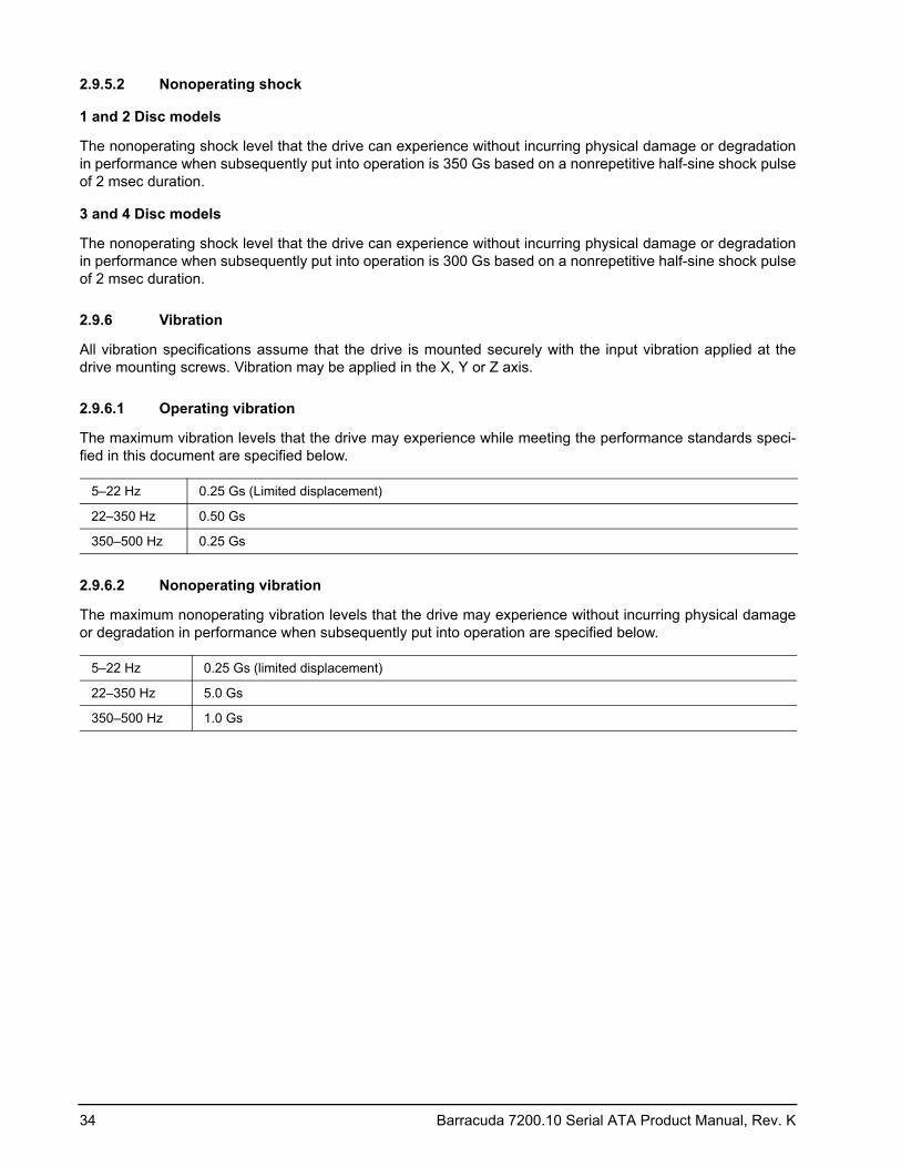
2.9.5.2 Nonoperating shock
1 and 2 Disc models
The nonoperating shock level that the drive can experience without incurring physical damage or degradation in performance when subsequently put into operation is 350 Gs based on a nonrepetitive half-sine shock pulse of 2 msec duration.
3 and 4 Disc models
The nonoperating shock level that the drive can experience without incurring physical damage or degradation in performance when subsequently put into operation is 300 Gs based on a nonrepetitive half-sine shock pulse of 2 msec duration.
2.9.6 Vibration
All vibration specifications assume that the drive is mounted securely with the input vibration applied at the drive mounting screws. Vibration may be applied in the X, Y or Z axis.
2.9.6.1 Operating vibration
The maximum vibration levels that the drive may experience while meeting the performance standards speci-fied in this document are specified below.
2.9.6.2 Nonoperating vibration
The maximum nonoperating vibration levels that the drive may experience without incurring physical damage or degradation in performance when subsequently put into operation are specified below.
5–22 Hz 0.25 Gs (Limited displacement)
22–350 Hz 0.50 Gs
350–500 Hz 0.25 Gs
5–22 Hz 0.25 Gs (limited displacement)
22–350 Hz 5.0 Gs
350–500 Hz 1.0 Gs
Barracuda 7200.10 Serial ATA Product Manual, Rev. K 35
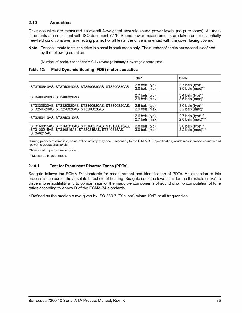
2.10 Acoustics
Drive acoustics are measured as overall A-weighted acoustic sound power levels (no pure tones). All mea-surements are consistent with ISO document 7779. Sound power measurements are taken under essentially free-field conditions over a reflecting plane. For all tests, the drive is oriented with the cover facing upward.
Note. For seek mode tests, the drive is placed in seek mode only. The number of seeks per second is defined by the following equation: (Number of seeks per second = 0.4 / (average latency + average access time)
*During periods of drive idle, some offline activity may occur according to the S.M.A.R.T. specification, which may increase acoustic and power to operational levels.
**Measured in performance mode.
***Measured in quiet mode.
2.10.1 Test for Prominent Discrete Tones (PDTs)
Seagate follows the ECMA-74 standards for measurement and identification of PDTs. An exception to this process is the use of the absolute threshold of hearing. Seagate uses the lower limit for the threshold curve* to discern tone audibility and to compensate for the inaudible components of sound prior to computation of tone ratios according to Annex D of the ECMA-74 standards.
* Defined as the median curve given by ISO 389-7 (Tf curve) minus 10dB at all frequencies.
Table 13: Fluid Dynamic Bearing (FDB) motor acoustics
Idle* Seek
ST3750640AS, ST3750840AS, ST3500630AS, ST3500830AS 2.8 bels (typ) 3.0 bels (max)
3.7 bels (typ)** 3.9 bels (max)**
ST3400620AS, ST3400820AS 2.7 bels (typ) 2.9 bels (max)
3.4 bels (typ)** 3.6 bels (max)**
ST3320620AS, ST3320820AS, ST3300620AS, ST3300820AS, ST3250620AS, ST3250820AS, ST3200820AS
2.5 bels (typ) 2.9 bels (max)
3.0 bels (typ)** 3.2 bels (max)**
ST3250410AS, ST3250310AS 2.6 bels (typ) 2.7 bels (max)
2.7 bels (typ)*** 2.8 bels (max)***
ST3160815AS, ST3160310AS, ST3160215AS, ST3120815AS, ST3120215AS, ST380815AS, ST380215AS, ST340815AS, ST340215AS
2.8 bels (typ) 3.0 bels (max)
3.0 bels (typ)*** 3.2 bels (max)***
36 Barracuda 7200.10 Serial ATA Product Manual, Rev. K
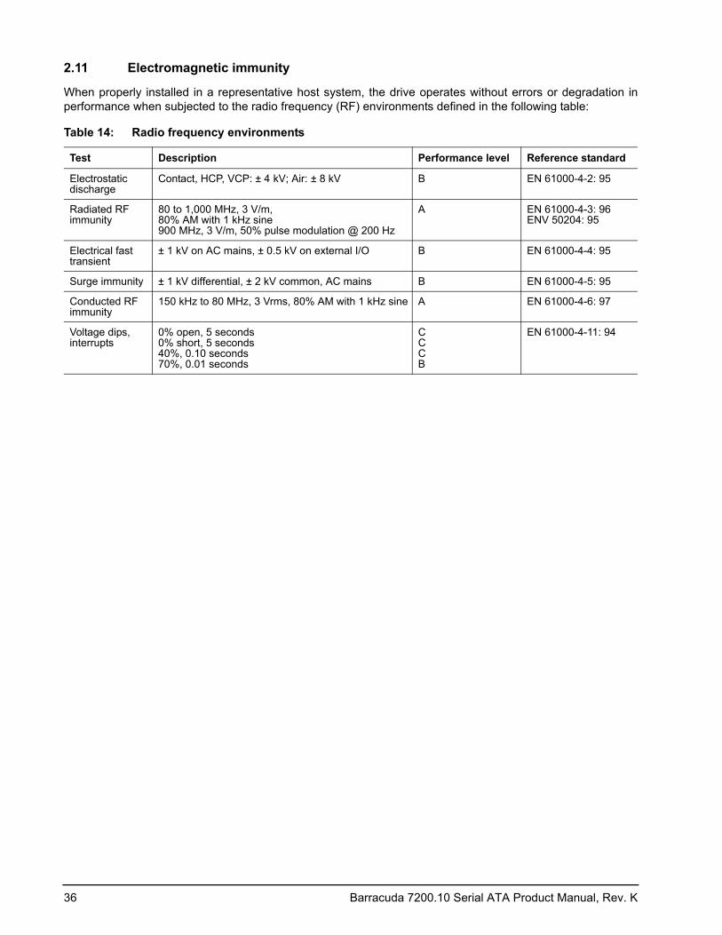
2.11 Electromagnetic immunity
When properly installed in a representative host system, the drive operates without errors or degradation in performance when subjected to the radio frequency (RF) environments defined in the following table:
Table 14: Radio frequency environments
Test Description Performance level Reference standard
Electrostatic discharge
Contact, HCP, VCP: ± 4 kV; Air: ± 8 kV B EN 61000-4-2: 95
Radiated RF immunity
80 to 1,000 MHz, 3 V/m, 80% AM with 1 kHz sine 900 MHz, 3 V/m, 50% pulse modulation @ 200 Hz
A EN 61000-4-3: 96 ENV 50204: 95
Electrical fast transient
± 1 kV on AC mains, ± 0.5 kV on external I/O B EN 61000-4-4: 95
Surge immunity ± 1 kV differential, ± 2 kV common, AC mains B EN 61000-4-5: 95
Conducted RF immunity
150 kHz to 80 MHz, 3 Vrms, 80% AM with 1 kHz sine A EN 61000-4-6: 97
Voltage dips, interrupts
0% open, 5 seconds 0% short, 5 seconds 40%, 0.10 seconds 70%, 0.01 seconds
C C C B
EN 61000-4-11: 94
Barracuda 7200.10 Serial ATA Product Manual, Rev. K 37
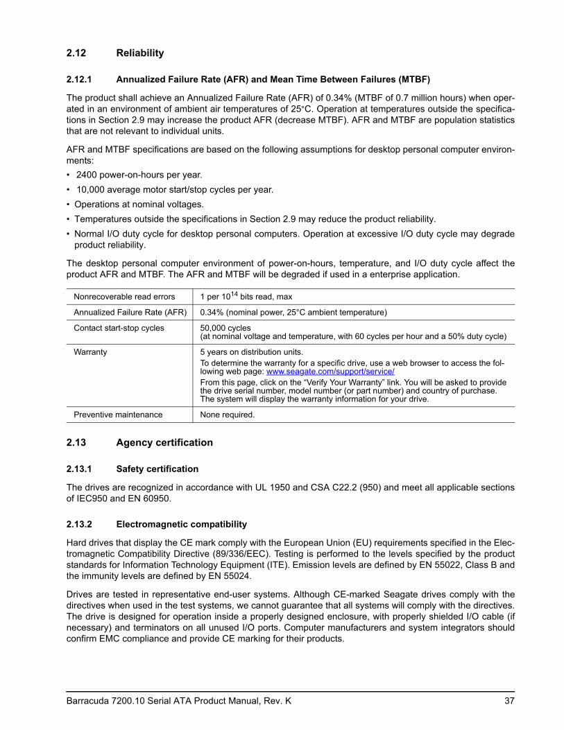
2.12 Reliability
2.12.1 Annualized Failure Rate (AFR) and Mean Time Between Failures (MTBF)
The product shall achieve an Annualized Failure Rate (AFR) of 0.34% (MTBF of 0.7 million hours) when oper-ated in an environment of ambient air temperatures of 25°C. Operation at temperatures outside the specifica-tions in Section 2.9 may increase the product AFR (decrease MTBF). AFR and MTBF are population statistics that are not relevant to individual units.
AFR and MTBF specifications are based on the following assumptions for desktop personal computer environ-ments: • 2400 power-on-hours per year. • 10,000 average motor start/stop cycles per year. • Operations at nominal voltages. • Temperatures outside the specifications in Section 2.9 may reduce the product reliability. • Normal I/O duty cycle for desktop personal computers. Operation at excessive I/O duty cycle may degrade
product reliability.
The desktop personal computer environment of power-on-hours, temperature, and I/O duty cycle affect the product AFR and MTBF. The AFR and MTBF will be degraded if used in a enterprise application.
2.13 Agency certification
2.13.1 Safety certification
The drives are recognized in accordance with UL 1950 and CSA C22.2 (950) and meet all applicable sections of IEC950 and EN 60950.
2.13.2 Electromagnetic compatibility
Hard drives that display the CE mark comply with the European Union (EU) requirements specified in the Elec-tromagnetic Compatibility Directive (89/336/EEC). Testing is performed to the levels specified by the product standards for Information Technology Equipment (ITE). Emission levels are defined by EN 55022, Class B and the immunity levels are defined by EN 55024.
Drives are tested in representative end-user systems. Although CE-marked Seagate drives comply with the directives when used in the test systems, we cannot guarantee that all systems will comply with the directives. The drive is designed for operation inside a properly designed enclosure, with properly shielded I/O cable (if necessary) and terminators on all unused I/O ports. Computer manufacturers and system integrators should confirm EMC compliance and provide CE marking for their products.
Nonrecoverable read errors 1 per 1014 bits read, max
Annualized Failure Rate (AFR) 0.34% (nominal power, 25°C ambient temperature)
Contact start-stop cycles 50,000 cycles (at nominal voltage and temperature, with 60 cycles per hour and a 50% duty cycle)
Warranty 5 years on distribution units.To determine the warranty for a specific drive, use a web browser to access the fol-lowing web page: www.seagate.com/support/service/From this page, click on the “Verify Your Warranty” link. You will be asked to provide the drive serial number, model number (or part number) and country of purchase. The system will display the warranty information for your drive.
Preventive maintenance None required.
38 Barracuda 7200.10 Serial ATA Product Manual, Rev. K
Korean RRL
If these drives have the Korea Ministry of Information and Communication (MIC) logo, they comply with para-graph 1 of Article 11 of the Electromagnetic Compatibility control Regulation and meet the Electromagnetic Compatibility (EMC) Framework requirements of the Radio Research Laboratory (RRL) Ministry of Information and Communication Republic of Korea.
These drives have been tested and comply with the Electromagnetic Interference/Electromagnetic Susceptibil-ity (EMI/EMS) for Class B products. Drives are tested in a representative, end-user system by a Korean-recog-nized lab.• Family name: Barracuda 7200.10• Certificate number: STX-L3510 (B)
Australian C-Tick (N176)
If these models have the C-Tick marking, they comply with the Australia/New Zealand Standard AS/NZS3548 1995 and meet the Electromagnetic Compatibility (EMC) Framework requirements of the Australian Communi-cation Authority (ACA).
2.13.3 FCC verification
These drives are intended to be contained solely within a personal computer or similar enclosure (not attached as an external device). As such, each drive is considered to be a subassembly even when it is individually mar-keted to the customer. As a subassembly, no Federal Communications Commission verification or certification of the device is required.
Seagate has tested this device in enclosures as described above to ensure that the total assembly (enclosure, disc drive, motherboard, power supply, etc.) does comply with the limits for a Class B computing device, pursu-ant to Subpart J, Part 15 of the FCC rules. Operation with noncertified assemblies is likely to result in interfer-ence to radio and television reception.
Radio and television interference. This equipment generates and uses radio frequency energy and if not installed and used in strict accordance with the manufacturer’s instructions, may cause interference to radio and television reception.
This equipment is designed to provide reasonable protection against such interference in a residential installa-tion. However, there is no guarantee that interference will not occur in a particular installation. If this equipment does cause interference to radio or television, which can be determined by turning the equipment on and off, you are encouraged to try one or more of the following corrective measures:• Reorient the receiving antenna.• Move the device to one side or the other of the radio or TV.• Move the device farther away from the radio or TV.• Plug the computer into a different outlet so that the receiver and computer are on different branch outlets.
If necessary, you should consult your dealer or an experienced radio/television technician for additional sug-gestions. You may find helpful the following booklet prepared by the Federal Communications Commission: How to Identify and Resolve Radio-Television Interference Problems. This booklet is available from the Super-intendent of Documents, U.S. Government Printing Office, Washington, DC 20402. Refer to publication num-ber 004-000-00345-4.
Barracuda 7200.10 Serial ATA Product Manual, Rev. K 39
2.14 Environmental protection
Seagate designs its products to meet environmental protection requirements worldwide, including regulations restricting certain chemical substances.
2.14.1 European Union Restriction of Hazardous Substances (RoHS) Directive
Seagate designs its products to meet environmental protection requirements worldwide, including regulations restricting certain chemical substances. A new law, the European Union Restriction of Hazardous Substances (RoHS) Directive, restricts the presence of chemical substances, including Lead, Cadmium, Mercury, Hexavalent Chromium, PBB and PBDE, in electronic products, effective July 2006. This drive is manufactured with components and materials that comply with the RoHS Directive.
2.14.2 China Restriction of Hazardous Substances (RoHS) Directive
This product has an Environmental Protection Use Period (EPUP) of 20 years. The following table contains information mandated by China's "Marking Requirements for Control of Pollution Caused by Electronic Information Products" Standard.
"O" indicates the hazardous and toxic substance content of the part (at the homogenous material level) is lower than the threshold defined by the China RoHS MCV Standard.
"X" indicates the hazardous and toxic substance content of the part (at the homogenous material level) is over the threshold defined by the China RoHS MCV Standard.
2.15 Corrosive environment
Seagate electronic drive components pass accelerated corrosion testing equivalent to 10 years exposure to light industrial environments containing sulfurous gases, chlorine and nitric oxide, classes G and H per ASTM B845. However, this accelerated testing cannot duplicate every potential application environment. Users should use caution exposing any electronic components to uncontrolled chemical pollutants and corrosive chemicals as electronic drive component reliability can be affected by the installation environment. The silver, copper, nickel and gold films used in Seagate products are especially sensitive to the presence of sulfide, chlo-ride, and nitrate contaminants. Sulfur is found to be the most damaging. In addition, electronic components should never be exposed to condensing water on the surface of the printed circuit board assembly (PCBA) or exposed to an ambient relative humidity greater than 95%. Materials used in cabinet fabrication, such as vulca-nized rubber, that can outgas corrosive compounds should be minimized or eliminated. The useful life of any electronic equipment may be extended by replacing materials near circuitry with sulfide-free alternatives.
2.14.2 中国限制危险物品的指令
“O"表示该部件(于同类物品程度上)所含的危险和有毒物质低于中国RoHS MCV标准所定义的门槛值。
“X "表示该部件(于同类物品程度上)所含的危险和有毒物质超出中国RoHS MCV标准所定义的门槛值。

40 Barracuda 7200.10 Serial ATA Product Manual, Rev. K
Barracuda 7200.10 Serial ATA Product Manual, Rev. K 41
3.0 Configuring and mounting the drive
This section contains the specifications and instructions for configuring and mounting the drive.
3.1 Handling and static-discharge precautions
After unpacking, and before installation, the drive may be exposed to potential handling and electrostatic dis-charge (ESD) hazards. Observe the following standard handling and static-discharge precautions:
Caution:
• Before handling the drive, put on a grounded wrist strap, or ground yourself frequently by touching the metal chassis of a computer that is plugged into a grounded outlet. Wear a grounded wrist strap throughout the entire installation procedure.
• Handle the drive by its edges or frame only.• The drive is extremely fragile—handle it with care. Do not press down on the drive top cover.• Always rest the drive on a padded, antistatic surface until you mount it in the computer.• Do not touch the connector pins or the printed circuit board.• Do not remove the factory-installed labels from the drive or cover them with additional labels. Removal voids
the warranty. Some factory-installed labels contain information needed to service the drive. Other labels are used to seal out dirt and contamination.
42 Barracuda 7200.10 Serial ATA Product Manual, Rev. K
3.2 Configuring the drive
Each drive on the Serial ATA interface connects point-to-point with the Serial ATA host adapter. There is no master/slave relationship because each drive is considered a master in a point-to-point relationship. If two drives are attached on one Serial ATA host adapter, the host operating system views the two devices as if they were both “masters” on two separate ports. Both drives behave as if they are Device 0 (master) devices.
Serial ATA drives are designed for easy installation. It is usually not necessary to set any jumpers on the drive for proper operation; however, if you connect the drive and receive a “drive not detected” error, your SATA-equipped motherboard or host adapter may use a chipset that does not support SATA speed autonegotiation. If you have a motherboard or host adapter that does not support autonegotiation:• Install a jumper as shown in Figure 3 below to limit the data transfer rate to 1.5 Gbits per second (and leave
the drive connected to the SATA-equipped motherboard or host adapter that doesn’t support autonegotiation) or
• Install a SATA host adapter that supports autonegotiation, leave the drive jumper block set to “Normal operation” (see Figure 3 below), and connect the drive to that adapter. This option has the benefit of not limiting the drive to a 1.5 Gbits/sec transfer rate.
Figure 3. Serial ATA connectors
3.3 Serial ATA cables and connectors
The Serial ATA interface cable consists of four conductors in two differential pairs, plus three ground connec-tions. The cable size may be 30 to 26 AWG with a maximum length of one meter (39.37 inches). See Table 15for connector pin definitions. Either end of the SATA signal cable can be attached to the drive or host.
For direct backplane connection, the drive connectors are inserted directly into the host receptacle. The drive and the host receptacle incorporate features that enable the direct connection to be hot pluggable and blind mateable.
For installations which require cables, you can connect the drive as illustrated in Figure 4.
Figure 4. Attaching SATA cabling
Each cable is keyed to ensure correct orientation. Barracuda 7200.10 Serial ATA drives support latching SATA connectors.
Jumper block
SATA interface connector
SATA power connector
Limit data transfer rate to1.5 Gbits per second
3.0 Gbits per second operation
Power cable
Signal cable
Signal connector
Power connector
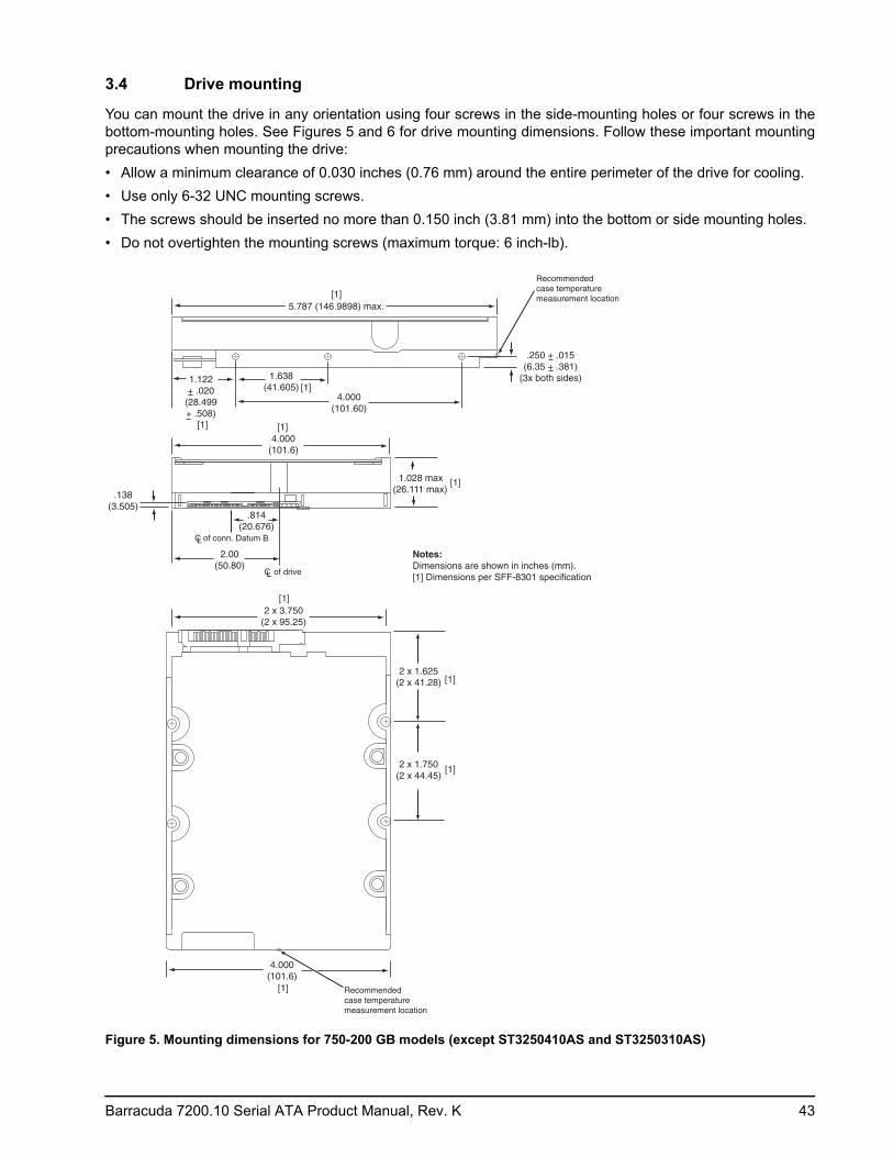
Barracuda 7200.10 Serial ATA Product Manual, Rev. K 43
3.4 Drive mounting
You can mount the drive in any orientation using four screws in the side-mounting holes or four screws in the bottom-mounting holes. See Figures 5 and 6 for drive mounting dimensions. Follow these important mounting precautions when mounting the drive:• Allow a minimum clearance of 0.030 inches (0.76 mm) around the entire perimeter of the drive for cooling.• Use only 6-32 UNC mounting screws.• The screws should be inserted no more than 0.150 inch (3.81 mm) into the bottom or side mounting holes.• Do not overtighten the mounting screws (maximum torque: 6 inch-lb).
Figure 5. Mounting dimensions for 750-200 GB models (except ST3250410AS and ST3250310AS)
4.000(101.6)
5.787 (146.9898) max.
1.028 max(26.111 max)
2.00(50.80)
1.638(41.605)
4.000(101.60)
2 x 1.750(2 x 44.45)
2 x 3.750(2 x 95.25)
CL of drive
[1]
Notes:Dimensions are shown in inches (mm).[1] Dimensions per SFF-8301 specification
[1]
[1]
[1]
1.122+ .020
(28.499+ .508)
[1]
[1]
[1]
[1]
CL of conn. Datum B
.814(20.676)
.138(3.505)
.250 + .015(6.35 + .381)
(3x both sides)
4.000(101.6)
2 x 1.625(2 x 41.28) [1]
Recommended case temperature measurement location
Recommended case temperature measurement location
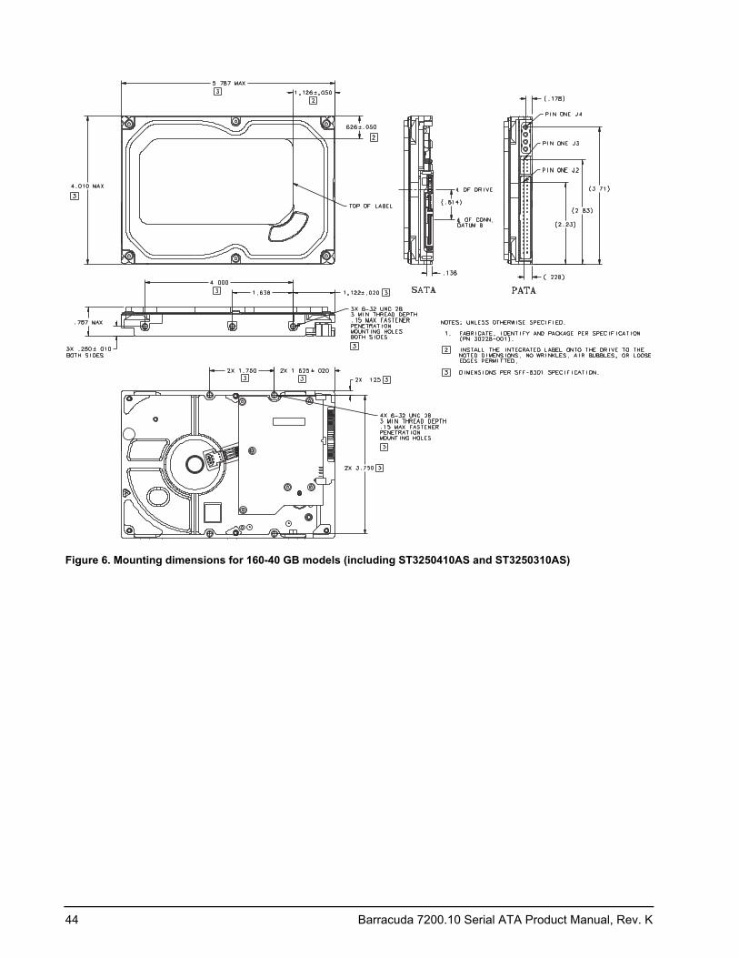
44 Barracuda 7200.10 Serial ATA Product Manual, Rev. K
Figure 6. Mounting dimensions for 160-40 GB models (including ST3250410AS and ST3250310AS)
Barracuda 7200.10 Serial ATA Product Manual, Rev. K 45
4.0 Serial ATA (SATA) interface
These drives use the industry-standard Serial ATA interface that supports FIS data transfers. It supports ATA programmed input/output (PIO) modes 0–4; multiword DMA modes 0–2, and Ultra DMA modes 0–6.
For detailed information about the Serial ATA interface, refer to the “Serial ATA: High Speed Serialized AT Attachment” specification.
4.1 Hot-Plug compatibility
Barracuda 7200.10 Serial ATA drives incorporate connectors which enable you to hot plug these drives in accordance with the Serial ATA Revision 2.5 specification. This specification can be downloaded from www.serialata.org.
46 Barracuda 7200.10 Serial ATA Product Manual, Rev. K
4.2 Serial ATA device plug connector pin definitions
Table 15 summarizes the signals on the Serial ATA interface and power connectors..
Notes:1. All pins are in a single row, with a 1.27 mm (0.050”) pitch.
2. The comments on the mating sequence apply to the case of backplane blindmate connector only. In this case, the mating sequences are:• the ground pins P4 and P12.• the pre-charge power pins and the other ground pins.• the signal pins and the rest of the power pins.
3. There are three power pins for each voltage. One pin from each voltage is used for pre-charge when installed in a blind-mate backplane configuration.
4. All used voltage pins (Vx) must be terminated.
Table 15: Serial ATA connector pin definitions
Segment Pin Function Definition
Signal
S1 Ground 2nd mate
S2 A+ Differential signal pair A from Phy
S3 A-
S4 Ground 2nd mate
S5 B- Differential signal pair B from Phy
S6 B+
S7 Ground 2nd mate
Key and spacing separate signal and power segments
Power
P1 V33 3.3V power
P2 V33 3.3V power
P3 V33 3.3V power, pre-charge, 2nd mate
P4 Ground 1st mate
P5 Ground 2nd mate
P6 Ground 2nd mate
P7 V5 5V power, pre-charge, 2nd mate
P8 V5 5V power
P9 V5 5V power
P10 Ground 2nd mate
P11 Ground or LED signal If grounded, drive does not use deferred spin
P12 Ground 1st mate.
P13 V12 12V power, pre-charge, 2nd mate
P14 V12 12V power
P15 V12 12V power
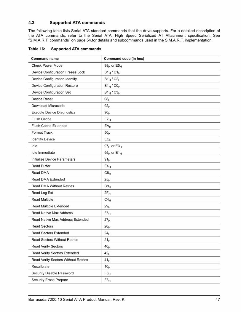
Barracuda 7200.10 Serial ATA Product Manual, Rev. K 47
4.3 Supported ATA commands
The following table lists Serial ATA standard commands that the drive supports. For a detailed description of the ATA commands, refer to the Serial ATA: High Speed Serialized AT Attachment specification. See “S.M.A.R.T. commands” on page 54.for details and subcommands used in the S.M.A.R.T. implementation.
Table 16: Supported ATA commands
Command name Command code (in hex)
Check Power Mode 98H or E5H
Device Configuration Freeze Lock B1H / C1H
Device Configuration Identify B1H / C2H
Device Configuration Restore B1H / C0H
Device Configuration Set B1H / C3H
Device Reset 08H
Download Microcode 92H
Execute Device Diagnostics 90H
Flush Cache E7H
Flush Cache Extended EAH
Format Track 50H
Identify Device ECH
Idle 97H or E3H
Idle Immediate 95H or E1H
Initialize Device Parameters 91H
Read Buffer E4H
Read DMA C8H
Read DMA Extended 25H
Read DMA Without Retries C9H
Read Log Ext 2FH
Read Multiple C4H
Read Multiple Extended 29H
Read Native Max Address F8H
Read Native Max Address Extended 27H
Read Sectors 20H
Read Sectors Extended 24H
Read Sectors Without Retries 21H
Read Verify Sectors 40H
Read Verify Sectors Extended 42H
Read Verify Sectors Without Retries 41H
Recalibrate 10H
Security Disable Password F6H
Security Erase Prepare F3H
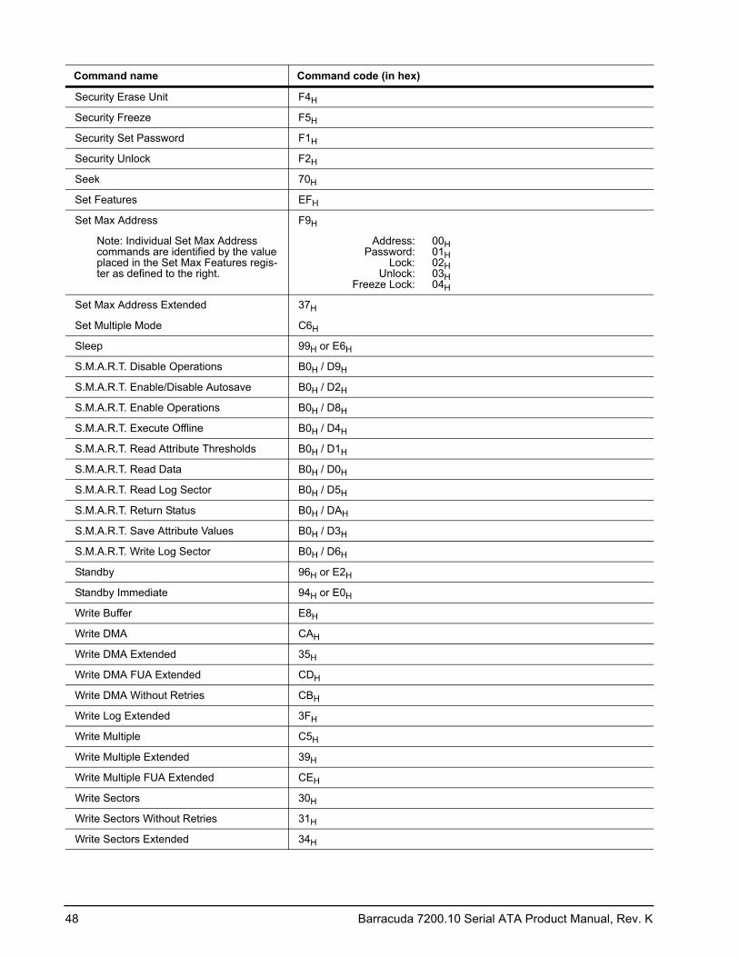
48 Barracuda 7200.10 Serial ATA Product Manual, Rev. K
Security Erase Unit F4H
Security Freeze F5H
Security Set Password F1H
Security Unlock F2H
Seek 70H
Set Features EFH
Set Max Address F9H
Note: Individual Set Max Address commands are identified by the value placed in the Set Max Features regis-ter as defined to the right.
Address: Password:
Lock: Unlock:
Freeze Lock:
00H 01H 02H 03H 04H
Set Max Address Extended 37H
Set Multiple Mode C6H
Sleep 99H or E6H
S.M.A.R.T. Disable Operations B0H / D9H
S.M.A.R.T. Enable/Disable Autosave B0H / D2H
S.M.A.R.T. Enable Operations B0H / D8H
S.M.A.R.T. Execute Offline B0H / D4H
S.M.A.R.T. Read Attribute Thresholds B0H / D1H
S.M.A.R.T. Read Data B0H / D0H
S.M.A.R.T. Read Log Sector B0H / D5H
S.M.A.R.T. Return Status B0H / DAH
S.M.A.R.T. Save Attribute Values B0H / D3H
S.M.A.R.T. Write Log Sector B0H / D6H
Standby 96H or E2H
Standby Immediate 94H or E0H
Write Buffer E8H
Write DMA CAH
Write DMA Extended 35H
Write DMA FUA Extended CDH
Write DMA Without Retries CBH
Write Log Extended 3FH
Write Multiple C5H
Write Multiple Extended 39H
Write Multiple FUA Extended CEH
Write Sectors 30H
Write Sectors Without Retries 31H
Write Sectors Extended 34H
Command name Command code (in hex)
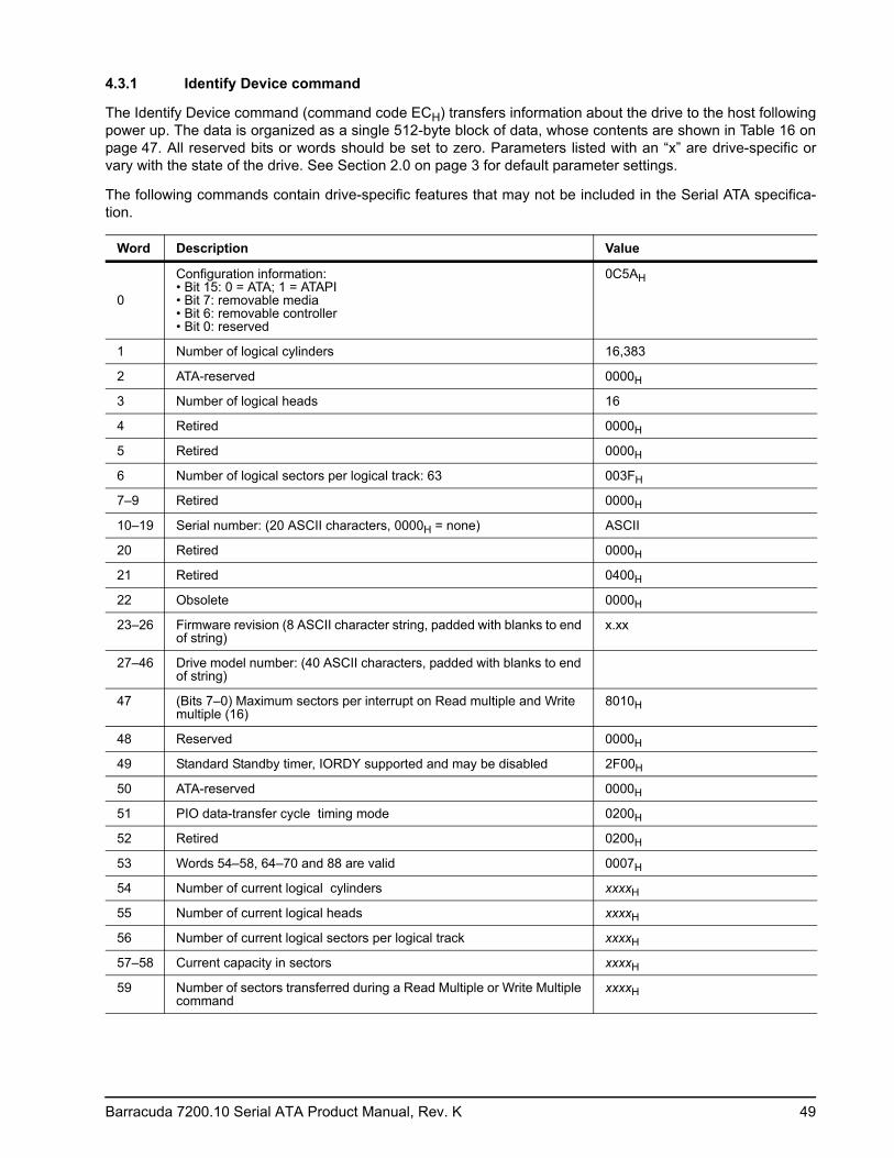
Barracuda 7200.10 Serial ATA Product Manual, Rev. K 49
4.3.1 Identify Device command
The Identify Device command (command code ECH) transfers information about the drive to the host following power up. The data is organized as a single 512-byte block of data, whose contents are shown in Table 16 onpage 47. All reserved bits or words should be set to zero. Parameters listed with an “x” are drive-specific or vary with the state of the drive. See Section 2.0 on page 3 for default parameter settings.
The following commands contain drive-specific features that may not be included in the Serial ATA specifica-tion.
Word Description Value
0
Configuration information: • Bit 15: 0 = ATA; 1 = ATAPI • Bit 7: removable media • Bit 6: removable controller • Bit 0: reserved
0C5AH
1 Number of logical cylinders 16,383
2 ATA-reserved 0000H
3 Number of logical heads 16
4 Retired 0000H
5 Retired 0000H
6 Number of logical sectors per logical track: 63 003FH
7–9 Retired 0000H
10–19 Serial number: (20 ASCII characters, 0000H = none) ASCII
20 Retired 0000H
21 Retired 0400H
22 Obsolete 0000H
23–26 Firmware revision (8 ASCII character string, padded with blanks to end of string)
x.xx
27–46 Drive model number: (40 ASCII characters, padded with blanks to end of string)
47 (Bits 7–0) Maximum sectors per interrupt on Read multiple and Write multiple (16)
8010H
48 Reserved 0000H
49 Standard Standby timer, IORDY supported and may be disabled 2F00H
50 ATA-reserved 0000H
51 PIO data-transfer cycle timing mode 0200H
52 Retired 0200H
53 Words 54–58, 64–70 and 88 are valid 0007H
54 Number of current logical cylinders xxxxH
55 Number of current logical heads xxxxH
56 Number of current logical sectors per logical track xxxxH
57–58 Current capacity in sectors xxxxH
59 Number of sectors transferred during a Read Multiple or Write Multiple command
xxxxH
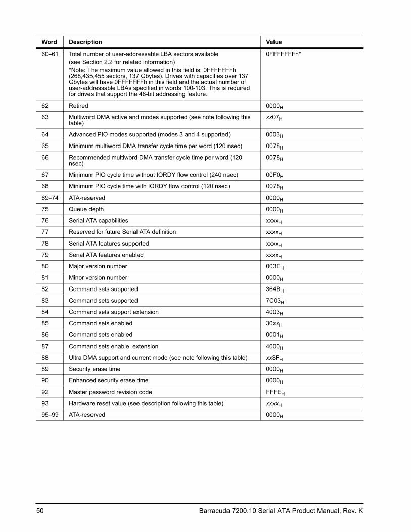
50 Barracuda 7200.10 Serial ATA Product Manual, Rev. K
60–61 Total number of user-addressable LBA sectors available(see Section 2.2 for related information)*Note: The maximum value allowed in this field is: 0FFFFFFFh (268,435,455 sectors, 137 Gbytes). Drives with capacities over 137 Gbytes will have 0FFFFFFFh in this field and the actual number of user-addressable LBAs specified in words 100-103. This is required for drives that support the 48-bit addressing feature.
0FFFFFFFh*
62 Retired 0000H
63 Multiword DMA active and modes supported (see note following this table)
xx07H
64 Advanced PIO modes supported (modes 3 and 4 supported) 0003H
65 Minimum multiword DMA transfer cycle time per word (120 nsec) 0078H
66 Recommended multiword DMA transfer cycle time per word (120 nsec)
0078H
67 Minimum PIO cycle time without IORDY flow control (240 nsec) 00F0H
68 Minimum PIO cycle time with IORDY flow control (120 nsec) 0078H
69–74 ATA-reserved 0000H
75 Queue depth 0000H
76 Serial ATA capabilities xxxxH
77 Reserved for future Serial ATA definition xxxxH
78 Serial ATA features supported xxxxH
79 Serial ATA features enabled xxxxH
80 Major version number 003EH
81 Minor version number 0000H
82 Command sets supported 364BH
83 Command sets supported 7C03H
84 Command sets support extension 4003H
85 Command sets enabled 30xxH
86 Command sets enabled 0001H
87 Command sets enable extension 4000H
88 Ultra DMA support and current mode (see note following this table) xx3FH
89 Security erase time 0000H
90 Enhanced security erase time 0000H
92 Master password revision code FFFEH
93 Hardware reset value (see description following this table) xxxxH
95–99 ATA-reserved 0000H
Word Description Value
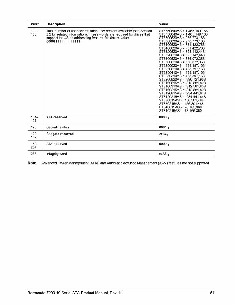
Barracuda 7200.10 Serial ATA Product Manual, Rev. K 51
Note. Advanced Power Management (APM) and Automatic Acoustic Management (AAM) features are not supported
100–103
Total number of user-addressable LBA sectors available (see Section 2.2 for related information). These words are required for drives that support the 48-bit addressing feature. Maximum value: 0000FFFFFFFFFFFFh.
ST3750640AS = 1,465,149,168 ST3750840AS = 1,465,149,168 ST3500630AS = 976,773,168 ST3500830AS = 976,773,168 ST3400620AS = 781,422,768 ST3400820AS = 781,422,768 ST3320620AS = 625,142,448 ST3320820AS = 625,142,448 ST3300620AS = 586,072,368 ST3300820AS = 586,072,368 ST3250620AS = 488,397,168 ST3250820AS = 488,397,168 ST3250410AS = 488,397,168 ST3250310AS = 488,397,168 ST3200820AS = 390,721,968 ST3160815AS = 312,581,808 ST3160310AS = 312,581,808 ST3160215AS = 312,581,808 ST3120815AS = 234,441,648 ST3120215AS = 234,441,648 ST380815AS = 156,301,488 ST380215AS = 156,301,488 ST340815AS = 78,165,360 ST340215AS = 78,165,360
104–127
ATA-reserved 0000H
128 Security status 0001H
129–159
Seagate-reserved xxxxH
160–254
ATA-reserved 0000H
255 Integrity word xxA5H
Word Description Value
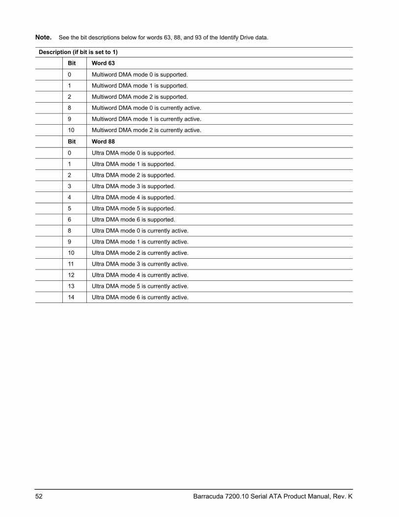
52 Barracuda 7200.10 Serial ATA Product Manual, Rev. K
Note. See the bit descriptions below for words 63, 88, and 93 of the Identify Drive data.
Description (if bit is set to 1)
Bit Word 63
0 Multiword DMA mode 0 is supported.
1 Multiword DMA mode 1 is supported.
2 Multiword DMA mode 2 is supported.
8 Multiword DMA mode 0 is currently active.
9 Multiword DMA mode 1 is currently active.
10 Multiword DMA mode 2 is currently active.
Bit Word 88
0 Ultra DMA mode 0 is supported.
1 Ultra DMA mode 1 is supported.
2 Ultra DMA mode 2 is supported.
3 Ultra DMA mode 3 is supported.
4 Ultra DMA mode 4 is supported.
5 Ultra DMA mode 5 is supported.
6 Ultra DMA mode 6 is supported.
8 Ultra DMA mode 0 is currently active.
9 Ultra DMA mode 1 is currently active.
10 Ultra DMA mode 2 is currently active.
11 Ultra DMA mode 3 is currently active.
12 Ultra DMA mode 4 is currently active.
13 Ultra DMA mode 5 is currently active.
14 Ultra DMA mode 6 is currently active.
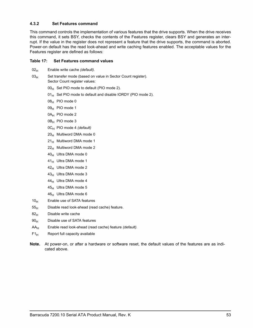
Barracuda 7200.10 Serial ATA Product Manual, Rev. K 53
4.3.2 Set Features command
This command controls the implementation of various features that the drive supports. When the drive receives this command, it sets BSY, checks the contents of the Features register, clears BSY and generates an inter-rupt. If the value in the register does not represent a feature that the drive supports, the command is aborted. Power-on default has the read look-ahead and write caching features enabled. The acceptable values for the Features register are defined as follows:
Note. At power-on, or after a hardware or software reset, the default values of the features are as indi-cated above.
Table 17: Set Features command values
02H Enable write cache (default).
03H Set transfer mode (based on value in Sector Count register).Sector Count register values:
00H Set PIO mode to default (PIO mode 2).
01H Set PIO mode to default and disable IORDY (PIO mode 2).
08H PIO mode 0
09H PIO mode 1
0AH PIO mode 2
0BH PIO mode 3
0CH PIO mode 4 (default)
20H Multiword DMA mode 0
21H Multiword DMA mode 1
22H Multiword DMA mode 2
40H Ultra DMA mode 0
41H Ultra DMA mode 1
42H Ultra DMA mode 2
43H Ultra DMA mode 3
44H Ultra DMA mode 4
45H Ultra DMA mode 5
46H Ultra DMA mode 6
10H Enable use of SATA features
55H Disable read look-ahead (read cache) feature.
82H Disable write cache
90H Disable use of SATA features
AAH Enable read look-ahead (read cache) feature (default).
F1H Report full capacity available
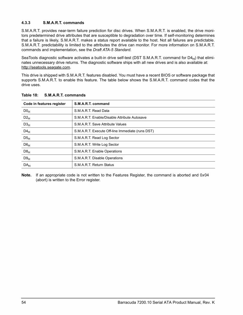
54 Barracuda 7200.10 Serial ATA Product Manual, Rev. K
4.3.3 S.M.A.R.T. commands
S.M.A.R.T. provides near-term failure prediction for disc drives. When S.M.A.R.T. is enabled, the drive moni-tors predetermined drive attributes that are susceptible to degradation over time. If self-monitoring determines that a failure is likely, S.M.A.R.T. makes a status report available to the host. Not all failures are predictable. S.M.A.R.T. predictability is limited to the attributes the drive can monitor. For more information on S.M.A.R.T. commands and implementation, see the Draft ATA-5 Standard.
SeaTools diagnostic software activates a built-in drive self-test (DST S.M.A.R.T. command for D4H) that elimi-nates unnecessary drive returns. The diagnostic software ships with all new drives and is also available at: http://seatools.seagate.com.
This drive is shipped with S.M.A.R.T. features disabled. You must have a recent BIOS or software package that supports S.M.A.R.T. to enable this feature. The table below shows the S.M.A.R.T. command codes that the drive uses.
Note. If an appropriate code is not written to the Features Register, the command is aborted and 0x 04 (abort) is written to the Error register.
Table 18: S.M.A.R.T. commands
Code in features register S.M.A.R.T. command
D0H S.M.A.R.T. Read Data
D2H S.M.A.R.T. Enable/Disable Attribute Autosave
D3H S.M.A.R.T. Save Attribute Values
D4H S.M.A.R.T. Execute Off-line Immediate (runs DST)
D5H S.M.A.R.T. Read Log Sector
D6H S.M.A.R.T. Write Log Sector
D8H S.M.A.R.T. Enable Operations
D9H S.M.A.R.T. Disable Operations
DAH S.M.A.R.T. Return Status
Barracuda 7200.10 Serial ATA Product Manual, Rev. K 55
5.0 Seagate Technology support services
Online services
InternetFor information regarding Seagate products and services, visit www.seagate.com. Worldwide support is available 24 hours daily by email for your questions.
Presales Support: [email protected]
Technical Support:[email protected]
Warranty Support:http://www.seagate.com/support/service/index.html
mySeagatemy.seagate.com is the industry's first Web portal designed specifically for OEMs and distributors. It provides self-service access to critical applications, personalized content and the tools that allow our partners to manage their Seagate account functions. Submit pricing requests, orders and returns through a single, password-protected Web interface-anytime, anywhere in the world.
spp.seagate.com spp.seagate.com supports Seagate resellers with product information, program benefits and sales tools. You may register for customized communications that are not available on the web. These communications contain product launch, EOL, pricing, promotions and other channel-related information. To learn more about the benefits or to register, go to spp.seagate.com, any time, from anywhere in the world.
Seagate Service Centers
Presales SupportOur Presales Support staff can help you determine which Seagate products are best suited for your specific application or computer system, as well as product availability and compatibility.
Technical SupportSeagate technical support is available to assist you online at support.seagate.com or through one of our call centers. Have your system configuration information and your “ST” model number available.
SeaTDD™ (+1-405-324-3655) is a telecommunications device for the deaf (TDD). You can send questions or comments 24 hours daily and exchange messages with a technical support specialist during normal business hours for the call center in your region.
56 Barracuda 7200.10 Serial ATA Product Manual, Rev. K
Customer Service Operations
Warranty ServiceSeagate offers worldwide customer support for Seagate products. Seagate distributors, OEMs and other direct customers should contact their Seagate Customer Service Operations (CSO) representative for warranty-related issues. Resellers or end users of drive products should contact their place of purchase or Seagate warranty service for assistance. Have your serial number and model or part number available.
Data Recovery ServicesSeagate offers data recovery services for all formats and all brands of storage media. Our data recovery services labs are currently located throughout the world. . Additional information, including an online request form and data loss prevention resources, is available at http://services.seagate.com/index.aspx
Authorized Service CentersSeagate Service Centers are available on a global basis for the return of defective products. Contact your customer support representative for the location nearest you.
USA/Canada/Latin America support servicesFor an extensive list of telephone numbers to technical support, presales and warranty service in USA/Canada/Latin America, including business hours, go to the "Contact Us" page on www.seagate.com.
Global Customer Support
Presales, Technical, and Warranty SupportCall Center Toll-free Direct dialUSA, Canada,and Mexico 1-800-SEAGATE +1-405-324-4700
Data Recovery ServicesCall Center Toll-free Direct dial FAXUSA, Canada, 1-800-475-01435 +1-905-474-2162 1-800-475-0158and Mexico +1-905-474-2459
Europe, the Middle East and Africa Support ServicesFor an extensive list of telephone numbers to technical support, presales and warranty service in Europe, the Middle East and Africa, go to the "Contact Us" page on www.seagate.com.
Asia/Pacific Support ServicesFor an extensive list of telephone numbers to technical support, presales and warranty service in Asia/Pacific, go to the "Contact Us" page on www.seagate.com.
Publication feedback surveyWe are interested in your comments and suggestions regarding this publication. Please take a few minutes to participate in our survey at the following URL:
http://survey.seagate.com/survey/techpubs.nsfThank you for your time and comments.
Barracuda 7200.10 Serial ATA Product Manual, Rev. K 57
Index
AACA 38acceleration 34acoustics 35Active 32Active mode 32actuator arm 30AFR 37Agency certification 37altitude 33Ambient temperature 33ambient temperature 29, 30Annualized Failure Rate 37Annualized Failure Rate (AFR) 37areal density 1, 27ATA commands 47Australia/New Zealand Standard AS/NZS3548 1995
38Australian Communication Authority (ACA) 38Australian C-Tick 38Average latency 29Average seek time 29
Bbuffer 28
Ccables and connectors 42cache 28capacity 26case temperature 33CE mark 37certification 37Check Power Mode 47China RoHS directive 39compatibility 37Conducted noise 31Conducted RF immunity 36Configuring the drive 41connectors 42Corrosive environment 39CSA C22.2 (950) 37cycles 37Cylinders 26
Ddata-transfer rates 1DC power 30Default logical geometry 26density 27
Device Configuration Freeze Lock 47Device Configuration Identify 47Device Configuration Restore 47Device Configuration Set 47Device Reset 47dimensions 43, 44disc surface 30dissipation 30Download Microcode 47duty cycle 37
EElectrical fast transient 36Electromagnetic compatibility 37Electromagnetic Compatibility (EMC) 38Electromagnetic Compatibility control Regulation 38Electromagnetic Compatibility Directive (89/336/EEC)
37Electromagnetic immunity 36Electrostatic discharge 36electrostatic discharge (ESD) 41EN 55022, Class B 37EN 55024 37EN 60950 37enclosures 38Environmental specifications 33error-correction algorithms 1errors 37ESD 41EU 37EU RoHS directive 39European Union (EU) requirements 37Execute Device Diagnostics 47
FFCC verification 38features 1Flush Cache 47Flush Cache Extended 47Format Track 47Formatted capacity 26
Ggeometry 26Gs 34guaranteed sectors 26
HHandling precautions 41heads 26height 28humidity 33
58 Barracuda 7200.10 Serial ATA Product Manual, Rev. K
II/O data-transfer rate 27I/O duty cycle 37Identify Device 47Identify Device command 49Idle 32, 47Idle Immediate 47Idle mode 30, 32IEC950 37Information Technology Equipment (ITE) 37Initialize Device Parameters 47Input noise ripple 31input voltage 30interface 27, 45interference 38internal data-transfer rate OD 27is 29ISO document 7779 35ITE 37
KKorea Ministry of Information and Communication
(MIC) 38Korean RRL 38
Llatency 29latency time 30LBA mode 26length 28logical geometry 26
Mmaintenance 37master/slave 2maximum temperature 33Mean Time Between Failures 37MIC 38mounting 43mounting screws 33mounting the drive 41MTBF 37
Nnoise 31nominal power 29Nonoperating shock 34Nonoperating vibration 34Nonrecoverable read errors 37
Ooperating 30
Operating power 30Operating shock 33Operating vibration 34
PPhysical characteristics 28point-to-point 2, 42Power consumption 30power consumption 30power dissipation 30Power modes 32Power specifications 30Power-management modes 32Power-on to Ready 29power-on-hours 37precautions 41printed circuit board 41programmable power management 32
Qquick reference 3
RRadiated RF immunity 36radio and television interference 38radio frequency (RF) 36random seeks 30Read Buffer 47Read DMA 47Read DMA Extended 47Read DMA without Retries 47read errors 37Read Log Ext 47Read Multiple 47Read Multiple Extended 47Read Native Max Address 47Read Native Max Address Extended 47Read Sectors 47Read Sectors Extended 47Read Sectors Without Retries 47Read Verify Sectors 47Read Verify Sectors Extended 47Read Verify Sectors Without Retries 47read/write actuator arm 30Read/write heads 26Read/write power 30Recalibrate 47recording density 27recording method 27Recording technology 27relative humidity 33Reliability 37RF 36RMS read/write current 31
Barracuda 7200.10 Serial ATA Product Manual, Rev. K 59
RoHS 39RRL 38
SS.M.A.R.T. Disable Operations 48S.M.A.R.T. Enable Operations 48S.M.A.R.T. Enable/Disable Autosave 48S.M.A.R.T. Execute Offline 48S.M.A.R.T. implementation 47S.M.A.R.T. Read Attribute Thresholds 48S.M.A.R.T. Read Data 48S.M.A.R.T. Read Log Sector 48S.M.A.R.T. Return Status 48S.M.A.R.T. Save Attribute Values 48S.M.A.R.T. Write Log sector 48Safety certification 37SATA 45screws 33sectors 26Sectors per track 26Security Disable Password 47Security Erase Prepare 47Security Erase Unit 48Security Freeze 48Security Set Password 48Security Unlock 48Seek 48seek mode 30Seek mode power 30Seek time 29Seeking 30Serial ATA (SATA) interface 45serial ATA ports 2Servo electronics 30servo electronics 30Set Features 48Set Max Address 48Set Max Address Extended 48Set Multiple Mode 48Shock 33single-track seeks 29Sleep 30, 32, 48Sleep mode 32sound 35Specification summary table 3spindle speed 27Spinup 30Spinup power 30Standby 30, 32, 48Standby Immediate 48Standby mode 30, 32standby timer 32Standby to Ready 29Start/stop times 29start-stop cycles 37
static-discharge 41subassembly 38support services 55Surge immunity 36
Ttechnical support services 55temperature 29, 33temperature gradient 33timer 32timers 32track density 27Track-to-track 29Track-to-track seek time 29
UUL 1950 37
VVibration 34voltage 30Voltage dips, interrupts 36Voltage tolerance 31
WWarranty 37weight 28wet bulb temperature 33width 28Write Buffer 48Write DMA 48Write DMA Extended 48Write DMA FUA Extended 48Write DMA Without Retries 48Write Log Extended 48Write Multiple 48Write Multiple Extended 48Write Multiple FUA Extended 48Write Sectors 48Write Sectors Extended 48Write Sectors Without Retries 48
60 Barracuda 7200.10 Serial ATA Product Manual, Rev. K

Seagate Technology LLC920 Disc Drive, Scotts Valley, California 95066-4544, USAPublication Number: 100402371, Rev. K, Printed in U.S.A.