Embed Size (px)
DESCRIPTION
Bank and channel protective liner procedure
Citation preview

BANK AND CHANNEL PROTECTIVE LINING DESIGN PROCEDURES
GEOTECHNICAL DESIGN PROCEDURE GDP-10
Revision #2
APRIL 2007
GEOTECHWGAL ENGINEERING BUREAU
NEW YORK STATE DEPARTMENT OF TRANSPORTATION
GEOTECfINIC,A.L DESIGN PROCEDURE: B.A.NK AND CHANNEL PROTECTIVE LINING DESIGN PROCEDURES
GDP-10 Revision 42
STATE OF NEW YORK DEP-ARTMENT OF TR-ANSPORTATION
GEOTECHNICAL ENGINEERING BUREAU
APRIL 2007
EB 07039
Page 1 of 59

ABSTRACT
This designn manual was prepared to provide procedures and guidelines for the design of batik and channel protective linings . The otliective of the manual is to achieve adequate protection against detrimental erosion by the most economical meatls . Data for design analyses have been assembled from selected sources for the convenience of the designer . Soil properties are also a factor in erosion, and the effects of soil type on the requirements for protection are discussed . Various types of batik and channel protection are described along with their limitations and advantages as determined from construction experience and field performance.
EB 07-039
Page 2 of 59

TABLE OF C'ONTENTS
Abstract 1 .
Introduction . . . . . . . . . . . . . . . . . . . . . . . . . . . . . . . . . . . . . . . . . . . . . . . . . . . . . . . . . . . . . . . . . . . . . . . . . . . . . . . . . . . . . . . . . . . . . . . . . . . . . . . . . . . . . . . . . . . . . . . . . . . . . . . . . . . 5 1 .1
Purpose of erosion-resistant design . . . . . . . . . . . . . . . . . . . . . . . . . . . . . . . . . . . . . . . . . . . . . . . . . . . . . . . . . . . . . . . . . . 5 1 .2
Scope of manual . . . . . . . . . . . . . . . . . . . . . . . . . . . . . . . . . . . . . . . . . . . . . . . . . . . . . . . . . . . . . . . . . . . . . . . . . . . . . . . . . . . . . . . . . . . . . . . 5 2 .
Conditions Leading to Erosion . . . . . . . . . . . . . . . . . . . . . . . . . . . . . . . . . . . . . . . . . . . . . . . . . . . . . . . . . . . . . . . . . . . . . . . . . . . . . . . . . . . . . . . . . . . . . . . . . . . . . . 6
3 .
Information Required For Protective Lining Design . . . . . . . . . . . . . . . . . . . . . . . . . . . . . . . . . . . . . . . . . . . . . . . . . . . . . . . . . . . . . . . . . .11
4 .
Selection of Lining Type . . . . . . . . . . . . . . . . . . . . . . . . . . . . . . . . . . . . . . . . . . . . . . . . . . . . . . . . . . . . . . . . . . . . . . . . . . . . . . . . . . . . . . . . . . . . . . . . . . . . . . . . . . . . .13 4.1
General considerations . . . . . . . . . . . . . . . . . . . . . . . . . . . . . . . . . . . . . . . . . . . . . . . . . . . . . . . . . . . . . . . . . . . . . . . . . . . . . . . . . . .13 4.2
Economic considerations . . . . . . . . . . . . . . . . . . . . . . . . . . . . . . . . . . . . . . . . . . . . . . . . . . . . . . . . . . . . . . . . . . . . . . . . . . . . . . . .13 5 .
Design of Protective Linings . . . . . . . . . . . . . . . . . . . . . . . . . . . . . . . . . . . . . . . . . . . . . . . . . . . . . . . . . . . . . . . . . . . . . . . . . . . . . . . . . . . . . . . . . . . . . . . . . . . . . . .16
EB 07-039
Page 3 of 59
2.1 General . . . . . . . . . . . . . . . . . . . . . . . . . . . . . . . . . . . . . . . . . . . . . . . . . . . . . . . . . . . . . . . . . . . . . . . . . . . . . . . . . . . . . . . . . . . . . . . . . . . . . . . . . . . . . 6 2.2 Natural oleanders or roan-made bends in the alignment of a channel . . . . . . . . . . . . . 6 2.3 Constrictions in a charnnel . . . . . . . . . . . . . . . . . . . . . . . . . . . . . . . . . . . . . . . . . . . . . . . . . . . . . . . . . . . . . . . . . . . . . . . . . . . . . . . .6 2.4 Changes in the roughness of the channel boundaries . . . . . . . . . . . . . . . . . . . . . . . . . . . . . . . . . . . . . . . 8 2.5 Changes in the slope of a channel bottom . . . . . . . . . . . . . . . . . . . . . . . . . . . . . . . . . . . . . . . . . . . . . . . . . . . . . . . . 8 2.6 Abrupt changes in the width of a channel . . . . . . . . . . . . . . . . . . . . . . . . . . . . . . . . . . . . . . . . . . . . . . . . . . . . . . . . 8 2.7 Junctions of channels. . . . . . . . . . . . . . . . . . . . . . . . . . . . . . . . . . . . . . . . . . . . . . . . . . . . . . . . . . . . . . . . . . . . . . . . . . . . . . . . . . . . . . . . 8 2.8 Excavation in a stream channel . . . . . . . . . . . . . . . . . . . . . . . . . . . . . . . . . . . . . . . . . . . . . . . . . . . . . . . . . . . . . . . . . . . . . . . . 8 2.9 Increased flow quantity . . . . . . . . . . . . . . . . . . . . . . . . . . . . . . . . . . . . . . . . . . . . . . . . . . . . . . . . . . . . . . . . . . . . . . . . . . . . . . . . . . . . 9 2.10 Compound problens . . . . . . . . . . . . . . . . . . . . . . . . . . . . . . . . . . . . . . . . . . . . . . . . . . . . . . . . . . . . . . . . . . . . . . . . . . . . . . . . . . . . . . . . 9 2.11 Summary . . . . . . . . . . . . . . . . . . . . . . . . . . . . . . . . . . . . . . . . . . . . . . . . . . . . . . . . . . . . . . . . . . . . . . . . . . . . . . . . . . . . . . . . . . . . . . . . . . . . . . . . . . 9
3.1 Flow quantity or velocity . . . . . . . . . . . . . . . . . . . . . . . . . . . . . . . . . . . . . . . . . . . . . . . . . . . . . . . . . . . . . . . . . . . . . . . . . . . . . . .11 3.2 Channel geometry . . . . . . . . . . . . . . . . . . . . . . . . . . . . . . . . . . . . . . . . . . . . . . . . . . . . . . . . . . . . . . . . . . . . . . . . . . . . . . . . . . . . . . . . . .11 3.3 Erodibility of foundation soils . . . . . . . . . . . . . . . . . . . . . . . . . . . . . . . . . . . . . . . . . . . . . . . . . . . . . . . . . . . . . . . . . . . . . . . .11 3.4 Possibility of non-uniform settlement . . . . . . . . . . . . . . . . . . . . . . . . . . . . . . . . . . . . . . . . . . . . . . . . . . . . . . . . . . . .11 3.5 Wave height . . . . . . . . . . . . . . . . . . . . . . . . . . . . . . . . . . . . . . . . . . . . . . . . . . . . . . . . . . . . . . . . . . . . . . . . . . . . . . . . . . . . . . . . . . . . . . . . . . . .11 3.6 Ice action . . . . . . . . . . . . . . . . . . . . . . . . . . . . . . . . . . . . . . . . . . . . . . . . . . . . . . . . . . . . . . . . . . . . . . . . . . . . . . . . . . . . . . . . . . . . . . . . . . . . . . . .12 3.7 Relative costs of lining types . . . . . . . . . . . . . . . . . . . . . . . . . . . . . . . . . . . . . . . . . . . . . . . . . . . . . . . . . . . . . . . . . . . . . . . . . .12
5.1 Ohj ectives . . . . . . . . . . . . . . . . . . . . . . . . . . . . . . . . . . . . . . . . . . . . . . . . . . . . . . . . . . . . . . . . . . . . . . . . . . . . . . . . . . . . . . . . . . . . . . . . . . . . . . .16 5 .2 Use of design charts . . . . . . . . . . . . . . . . . . . . . . . . . . . . . . . . . . . . . . . . . . . . . . . . . . . . . . . . . . . . . . . . . . . . . . . . . . . . . . . . . . . . . . . .16 5.3 Evaluation of various lining types . . . . . . . . . . . . . . . . . . . . . . . . . . . . . . . . . . . . . . . . . . . . . . . . . . . . . . . . . . . . . . . . . 29
5.3.1 Grass linings . . . . . . . . . . . . . . . . . . . . . . . . . . . . . . . . . . . . . . . . . . . . . . . . . . . . . . . . . . . . . . . . . . . . . . . . . . . . . . . . . . . . . . . . . . . . . . . . . . . 29 5.3.2 Dumped Stone linings . . . . . . . . . . . . . . . . . . . . . . . . . . . . . . . . . . . . . . . . . . . . . . . . . . . . . . . . . . . . . . . . . . . . . . . . . . . . . . . . . . . . 32 5.3.3 Paved or grouted linings . . . . . . . . . . . . . . . . . . . . . . . . . . . . . . . . . . . . . . . . . . . . . . . . . . . . . . . . . . . . . . . . . . . . . . . . . . . . . . . . .36 5.3.4 Dry rip-rap and bagged concrete . . . . . . . . . . . . . . . . . . . . . . . . . . . . . . . . . . . . . . . . . . . . . . . . . . . . . . . . . . . . . . . . . . . .38 5.3.5 Gabions . . . . . . . . . . . . . . . . . . . . . . . . . . . . . . . . . . . . . . . . . . . . . . . . . . . . . . . . . . . . . . . . . . . . . . . . . . . . . . . . . . . . . . . . . . . . . . . . . . . . . . . . . . .38 5.3.6 Fabriform . . . . . . . . . . . . . . . . . . . . . . . . . . . . . . . . . . . . . . . . . . . . . . . . . . . . . . . . . . . . . . . . . . . . . . . . . . . . . . . . . . . . . . . . . . . . . . . . . . . . . . . .41 5.3.7 Soil cement . . . . . . . . . . . . . . . . . . . . . . . . . . . . . . . . . . . . . . . . . . . . . . . . . . . . . . . . . . . . . . . . . . . . . . . . . . . . . . . . . . . . . . . . . . . . . . . . . . . . . 41 5.3.8 Closed pipe drairi . . . . . . . . . . . . . . . . . . . . . . . . . . . . . . . . . . . . . . . . . . . . . . . . . . . . . . . . . . . . . . . . . . . . . . . . . . . . . . . . . . . . . . . . . . . 41

5 .4
Required extent of linings . . . . . . . . . . . . . . . . . . . . . . . . . . . . . . . . . . . . . . . . . . . . . . . . . . . . . . . . . . . . . . . . . . . . . . . . . . . . . . 43 5.4.1
Stream channel lniulgs . . . . . . . . . . . . . . . . . . . . . . . . . . . . . . . . . . . . . . . . . . . . . . . . . . . . . . . . . . . . . . . . . . . . . . . . . . . . . . . . . . . 43 5.4.2
Small roadside drainage channels . . . . . . . . . . . . . . . . . . . . . . . . . . . . . . . . . . . . . . . . . . . . . . . . . . . . . . . . . . . . . . . . . .48 5.5
Protection against wave action . . . . . . . . . . . . . . . . . . . . . . . . . . . . . . . . . . . . . . . . . . . . . . . . . . . . . . . . . . . . . . . . . . . . . . .48 6 .
Protection at Culvert and Paved Channel Outlets . . . . . . . . . . . . . . . . . . . . . . . . . . . . . . . . . . . . . . . . . . . . . . . . . . . . . . . . . . . . . . . . . . . . . . . 50 6.1
Need for protection . . . . . . . . . . . . . . . . . . . . . . . . . . . . . . . . . . . . . . . . . . . . . . . . . . . . . . . . . . . . . . . . . . . . . . . . . . . . . . . . . . . . . . . . . 50 6.2
Design of dumped stone protective aprons . . . . . . . . . . . . . . . . . . . . . . . . . . . . . . . . . . . . . . . . . . . . . . . . . . . . 50 6.3
Other types of protection . . . . . . . . . . . . . . . . . . . . . . . . . . . . . . . . . . . . . . . . . . . . . . . . . . . . . . . . . . . . . . . . . . . . . . . . . . . . . . . . 53 7 .
Filter or Bedding Layers. . . . . . . . . . . . . . . . . . . . . . . . . . . . . . . . . . . . . . . . . . . . . . . . . . . . . . . . . . . . . . . . . . . . . . . . . . . . . . . . . . . . . . . . . . . . . . . . . . . . . . . . . . . . . . 5 5 7.1
The need for filter or bedding layers . . . . . . . . . . . . . . . . . . . . . . . . . . . . . . . . . . . . . . . . . . . . . . . . . . . . . . . . . . . . . . 5 5 7.2
Granular filter or bedding material . . . . . . . . . . . . . . . . . . . . . . . . . . . . . . . . . . . . . . . . . . . . . . . . . . . . . . . . . . . . . . . . 56 7.3
Geotextile bedding . . . . . . . . . . . . . . . . . . . . . . . . . . . . . . . . . . . . . . . . . . . . . . . . . . . . . . . . . . . . . . . . . . . . . . . . . . . . . . . . . . . . . . . . . 56 Referetlces . . . . . . . . . . . . . . . . . . . . . . . . . . . . . . . . . . . . . . . . . . . . . . . . . . . . . . . . . . . . . . . . . . . . . . . . . . . . . . . . . . . . . . . . . . . . . . . . . . . . . . . . . . . . . . . . . . . . . . . . . . . . . . . . . . . . . . . . . . . . 5 8 _Appendix . . . . . . . . . . . . . . . . . . . . . . . . . . . . . . . . . . . . . . . . . . . . . . . . . . . . . . . . . . . . . . . . . . . . . . . . . . . . . . . . . . . . . . . . . . . . . . . . . . . . . . . . . . . . . . . . . . . . . . . . . . . . . . . . . . . . . . . . . . . . . . 5 9
A
Sample Problems (LTS Customary Units) . . . . . . . . . . . . . . . . . . . . . . . . . . . . . . . . . . . . . . . . . . . . . . . . . . . . A-1 B
Sample Problems (International System of Units) . . . . . . . . . . . . . . . . . . . . . . . . . . . . . . . . . . . . . . . B-1

1 . INTRODUCTION
1 .1
Purpose of erosion-resistant desi hi preparing the design of a highway project, the engineer usually has to design channels to cant' water . Such channels range fi-orn small roadside drainage ditches or gutters to major river relocations . In addition, highway embankriients and struct ires often have to be located in or adjacent to existing rivers, streams, lances, reservoirs or other bodies of water .
A newly constructed channel or a natural channel modified by man will generally experience accelerated erosion of the banks and scour of the bottom at some locations, while sediments will be deposited at others . A channel may be modified by changing its width or alignment, or by construction in or adjacent to the channel which will alter the natural flow boundaries at any flow stage . Failure to consider in design the erosive power of water may have the following adverse consequences :
1) Damage to or destruction of the facility . 2) Damage to adjacent property .
Pollution of surface waters by eroded soils .
Iii order to achieve a successful design, the engineer not only has to compute the design flow and provide adequate channel capacity to carry thus flow, but must also :
1) Recognize conditions that are conducive to erosion. 2) Ellinirlate or alleviate erosive conditions and/or provide adequate protection against
significant erosion damage to the transportation facility or adjacent property .
1 .2
Scope of manual This manual is intended to provide the designer with guidelines for erosion-resistant design. For thus purpose, the manual contains the following information :
1)
A descrrl)tioii of causes of erosioii acid ilietliods of avoiding it. 2) A description of commonly used types of protective linings . 3) Information gathered by NYSDOT and other agencies, for the selection of an
appropriate type of protective lining.
This manual is not a reference on other aspects of drainage design, such as hydraulics, hydrology. and culvert design . A few charts dealing with open channel flow have been assembled from other sources for the designer's convenience .
Also outside the scope of this manual is the design of structure foundations to prevent damage by scour.
After examlllation of this manual, some designer's may be disappointed that stream and channel barilL protection design cannot be reduced entirely to a numerical process . However, the interaction of flowing water with soil and rock particles in a practical situation is so complex that this is not possible . The most adequate and economic solution to any erosion or scour problem can only be arrived at by a combination of analysis. experience and good judgment . The manual attempts to include as many considerations as possible to supplement the latter two factors in the decision process .
EB 07-039
Page 5 of 59

2 . CONDITIONS LEADING TO EROSION
2.1 General Flowing water exerts a force, proportional to the square of its velocity, on objects in its path . The force on an object in a stream will increase by a factor of four if the water velocity is doubled . Erosion takes place when the water force exceeds the forces tending to keep a soil or rock particle in its position . In channels with steep grades or steep side slopes ; the tendency of soil or rock particles to move down the slope as a consequence of gravity reduces the magnitude of water force necessary to cause movement.
The lilkelilnood and severity of erosion is greatly influenced by soil type . Other factors remaining constant, the erosion resistance of a soil increases with increasing grain size, increasing plasticity and increasing relative density .
Certain conditions of channel geometry and/or roughness increase flow velocities or change the direction of flow so as to favor the occurrence of erosion . The most coninlon of these conditions and methods of avoiding them are described in subsequent sections . These problems can occur in all types of channels fi-om small roadside drainage ditches or gutters to major streams and rivers . However, sonic conditions will be more con-non in smaller, some in larger channels .
2.2
Natural meanders or man-made bends In the, ahgnnnent of a channel . Erosion and scour take place, unless adequate protection is provided, on the outside of meanders or bends, where the flow impinges on the bank (Fig. 1) . In the case of narrow man-made channels carrying high-speed flows, the stream of water floNA?ing at a high velocity toward the outside of a bend may be deflected against the inside bank and cause erosion there also (Fig . 2) . In order to limit erosion, sharp bends should be avoided when relocating streams or rivers, or designing roadside drainage channels, if at all possible . If erosion of the outside bank in a new or existing bend will result in an undesirable condition, adequate protection should be provided .
2.3
Constrictions in a channel Constrictions or contractions may be the result of the presence of highway embanlanents, bridge abutments or bridge piers located) within or adjacent to the channel . thereby constricting it laterally (Fig . 2). A protective lining placed on the bottoms of an erodible channel constricts it vertically, as may a bridge superstructure where clearance is inadequate at flood flows . A culvert may constrict a channel both laterally and vertically.
The flow velocity is increased at constrictions, resulting in erosion of the banks and scour of the bottom both above and below the constriction, unless protection is provided . In the case of a bridge having ; a pier in the channel of a. narrow stream, the resulting scour may endanger the approach ennbanl nents and even cause movement of the abutments toward the stream . If thus type of situation cannot be avoided by eliminating the pier or locating it outside the channel limits, scour should be anticipated and the approach embankments protected by a properly designed lining. The bridge itself, of course, should be supported on a foundation designed taking scour into account .
EB 07-039
Page 6 of 59

.i
FIG. I
EROSION, AND ULTIMATELY A SLOPE FAILURE, OF THE OUTSIDE BANK OF A MEANDER
EB 07-039
Page 7 of 59
FIG. 2 CHANNEL BEND IN BACKGROUND DEFLECTS FLOW TOWARDS BRIDGE ABUTMENT AND UNDERMINES FOOTING.
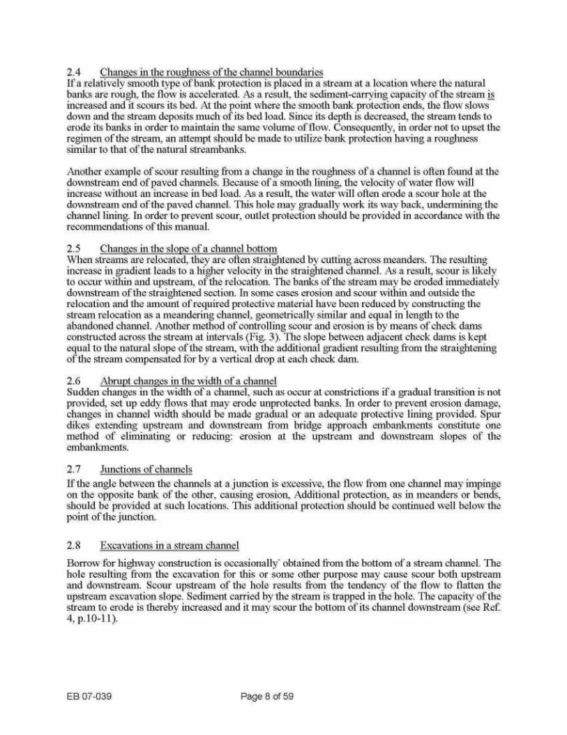
2.4
Changes in the roughness of the channel boundaries If a relatively smooth type of batik protection is placed in a stream at a location where the natural batiks are rough, the flow is accelerated . As a result, the sednnent-carrying capacity of the streaun is increased and it scours its bed. At the point where the smooth batik protection ends, the flow slows down and the stream deposits much of its bed load . Since its depth is decreased, the stream tends to erode its batiks in order to maintain the same volume of flow . Consequently, in order not to upset the regimen of the stream ; an attempt should be made to utilize bank protection having a rougXuless similar to that of the natural streannbanks .
Another example of scour resulting from a change in the rougluless of a channel is often found at the downstream end of paved channnels . Because of a smooth lining, the velocity of water flow will increase without an increase in bed load. ks a result, the water will often erode a scour hole at the downstream end of the paved channel . This hole may gradually work its way back, undermining the chanlzel lining . In order to prevent scour, outlet protection should be provided in accordance with the recommendations of this manual .
2.5
Changes in the slope of a channel bottom When streams are relocated, they are often straightened by cutting across meanders . The resulting increase in gradient leads to a higher velocity in the straightened channel . As a result, scour is likely to occur within and upstream, of the relocation. The batiks of the stream may be eroded liinlnnediately downstream of the straightened section . In some cases erosion and scour within and outside the relocation and the amount of required protective material have been reduced by constructing the stream relocation as a meandering channel, geometrically similar and equal in length to the abandoned channel. Another method of controlling scour and erosion is by means of check dann.5 constructed across the stream at intervals (Fig. 3) . The slope between adjacent check dams is kept equal to the natural slope of the stream, with the additional gradient resulting from the straightening of the stream compensated for by a vertical drop at each check dam.
2.6
Abrupt changes in the width of a clianliel Sudden changes in the width of a chalunel, such as occur at constrictions if a gradual transition is not provided, set up eddy flo`vs that may erode unprotected banks . In order to prevent erosion damage, changes in channel width should be made gradual or an adequate protective lining provided. Spur dikes extending upstream and downstream from bridge approach embanlclnents constitute one method of elninuiatnng or reducing : erosion at the upstream and downstream slopes of the. embankments .
2.7
Junctions of channels If the angle bet'"ven the channels at a junction is excessive, the flow from one channel may impinge on the opposite bank of the other, causing erosion, Additional protection, as in meanders or bends, should be provided at such locations . Thus additional protection should be continued well below the, point of the junction .
2.8
Excavations in a stream channel Borrow for higliNA=ay construction is occasionally obtained from the bottom of a stream channel . The hole resulting from the excavation for this or some other purpose may cause scour both upstream and downstream . Scour upstream of the hole results from the tendency of the flow to flatten the upstream excavation slope . Sediment carried by the stream is trapped in the hole . The capacity of the stream to erode is thereby increased and it may scour the bottom of its channel downstream (see Ref. 4, p.10-11) .
EB 07-039
Page 8 of 59
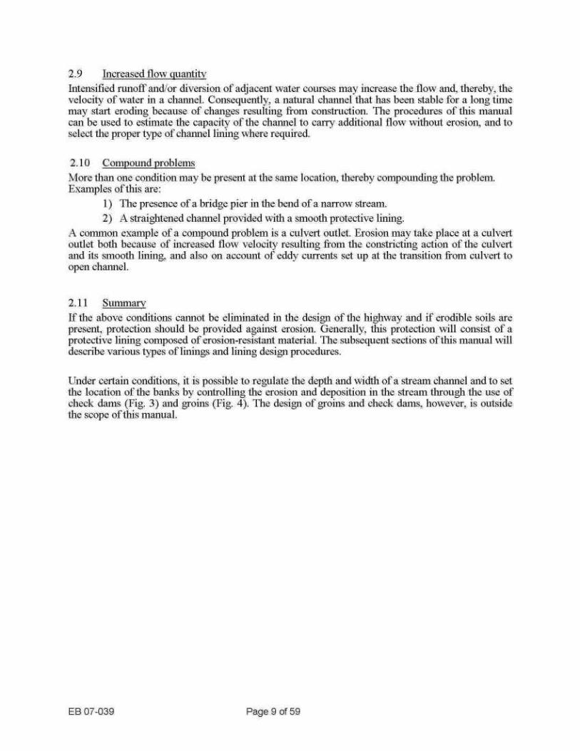
2.9
Increased floNi,, quantity Intensified runoff and/or diversion of adjacent water courses may increase the flow and, thereby, the velocity of water in a channel . Consequently, a natural channel that has been stable for a long time may start eroding because of changes resulting from construction . The procedures of this manual can be used to estimate the capacity of the channel to carry additional flow without erosion, and to select the proper type of channel lining
,here required.
2.10
Compound problems More than one condition may be present at the same location, thereby compounding the problem. Examples of this are :
1) The presence of a bridge pier in the bend of a narrow stream. 2) A straightened channel provided with a smooth protective lining .
A common example of a compound problem is a culvert outlet . Erosion may take place at a culvert outlet both because of increased flow velocity resulting from the constricting action of the culvert and its smooth lining, and also on account of eddy currents set up at the transition from culvert to open channel .
2.11 Summa If the above conditions cannot be eliminated in the design of the highway and if erodible soils are present, protection should be provided against erosion . Generally, this protection will consist of a protective lining composed of erosion-resistant material . The subsequent sections of this manual will describe various types of linings and lining design procedures .
Under certain conditions, it is possible to regulate the depth and width of a stream channel and to set the location of the banks by controlling the erosion and deposition in the stream through the use of check dams (Fig. 3) and groins (Fig. 4) . The design of groins and check dawns . however . is outside the scope of tills manual .
EB 07-039
Page 9 of 59

EB 07-039
Page 10 of 59
FIG. 3
CHECK D,"IS IN A STRE.,111'I RELOCATION
FIG. 4
USE OF GROINS TO CONTROL FLOW AND EROSION IN A RI'`ER

3 . INFORMATION REQUIRED FOR PROTECTIVE LINING DESIGN
3.1 Flow quantity or velocity Normally, protective linings should be designed on the basis of the flow quantity or average flow velocity OCCUITing with such a fi-ecluency that the risk of failure of the protection and damage to the protected facility will be acceptable . Not less than a 20-year- design storm or flood should be used for linings, even where damage will not result in interruption of highway traffic or have other major effects .
The U. S . Geologic Survey, Water Resources Division, has accumulated data on the discharge and velocity characteristics of many waterways throughout New York State . They can provide thus information for existing streams and perform analyses of the change in velocity and flow characteristics for channel relocations. This is a cooperative program with the New York State Department of Transportation and all requests for analyses of this type should be directed to the Deputy Chief Engineer (Structures) . The Office of Structures is the liaison between the Department and the U . S . Geologic Survey in this matter .
The flow in smaller streams and roadside drainage channels should be computed by hydrologic methods . Selection of a protective lining should not be based on a velocity measured by means of a current meter.
3.2
Channel geometry In existing streams the designer can determine the channel geometry--depth, gradient, side slopes, curvatilre. i unctions. and constrictions--from field survey data . In new channels the designer himself
.y of the channel .
3.3
Erodibilitv of foundation soils The susceptibility of soils to erosion varies within wide limits. As a result of glacial action, the soils in New York State are extremely variable and soils with very high and very low erosion resistance can occur within a short distance on the same project . The Regional Geotechnical Engineer should be contacted for information regarding the erosion resistance of soils at specific locations . He may utilize information from subsurface explorations, apply his knotivledge of the properties and extent of different depositional soils units, and evaluate past erosion problems in the particular soil type . Based on the above data, he will be able to point out areas of specific soil types on a project and indicate the relative susceptibility to erosion of each soil type .
3.4
Possibility of non-uniform settlement Non-uniform settlement as a result of soft foundation soils can lead to cracking of paved or grouted linings and to undesirable movements of individual particles of dry rip-rap . The presence or absence of such soils should be ascertained from the Regional Geotechnnical Engineer .
3.5
Wave height In wide rivers, lakes, reservoirs, and the ocean, all or most of the erosion by water results from wave action . For inland bodies of water, wave height can be estimated from information given in this manual if the wind velocity and fetch are known. Wind velocities and directions can be detenlli led from observations made at the nearest weather station operated by the National Oceanic and atmospheric adminis-tration of the U. S . Department of Conunerce . The fetch can be scaled from a plan sheet or from a map.
EB 07-039
Page 1 1 of 59

The design of protection against ocean waves is not covered by this manual and should he based on local experience .
3.6
Ice action An idea of the severity of ice action at a site may be obtained from the ko,~vn climatic conditions of the area supplemented by information obtained from persona familiar with local conditions
3.7
Relative costs oflinitig types The relative costs of various types of linings can be ascertained from an analysis of bid prices on previous projects in the area . The need for maintenance and the anticipated cost of maintenance should be considered when perfortnitlg an economic comparison of lining types.
EB 07-039
Page 1 2 of 59
4 . SELECTION OF LINING TYPE
4.1
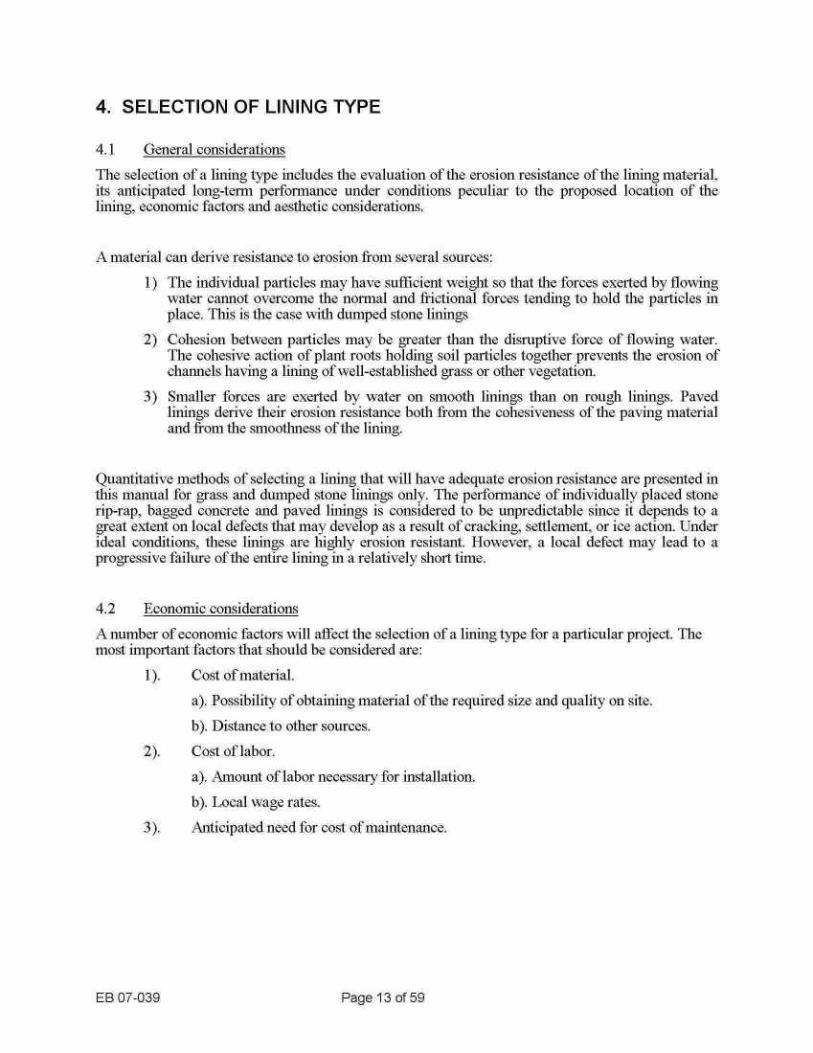
General considerations The selection of a lining type includes the evaluation of the erosion resistance of the lining material . its anticipated long-tern performance under conditions peculiar to the proposed location of the lining, economic factors and aesthetic considerations .
A material can derive, resistance to erosion from several sources : 1) The indi-,Fidual particles may have sufficient weight so that the forces exerted by flowing
water cannot overcome the normal and frictional forces tending to hold the particles in place . This is the case with dumped stone linings
4.2
Economic considerations
EB 07-039
Page 1 3 of 59
2) Cohesion between particles may be greater than the disruptive force of flowing water . The cohesive action of plant roots holding soil particles together prevents the erosion of channels having a lining of well-established grass or other vegetation .
3) Smaller forces are exerted by water on smooth linings than on rough linings . Paved linings derive their erosion resistance both from the cohesiveness of the paving material and from the smoothness of the lining.
Quantitative methods of selecting a lining that will have adequate erosion resistance are presented in this manual for grass and dumped stone linings only . The performance of individually placed stone rip-rap, bagged concrete and paved linings is considered to be unpredictable since it depends to a great extent on local defects that may develop as a result of cracking, settlement, or ice action . Under ideal conditions, these linings are highly erosion resistant. However, a local defect may lead to a progressive failure of the entire lining in a relatively short time .
A number of economic factors will affect the selection of a lining type for a particular project . The most important factors that should be considered are :
1) .
Cost of material . a). Possibility of obtaining material of the required size and quality on site . b) . Distance to other sources .
2) .
Cost of labor . a). Amount of labor necessary for installation . b) . Local wage rates . Anticipated need for cost of maintenance .
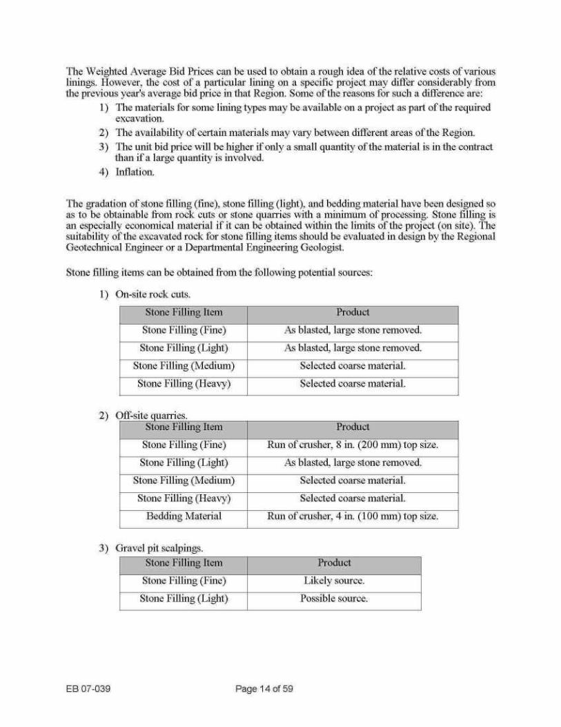
The Weighted Average Bid Prices call be used to obtain a rough idea of the relative costs of various linings . However, the cost of a particular lining on a specific project may differ considerably from the previous year's average bid price in that Region . Some of the reasons for such a difference are :
1) The materials for some lining types may be available on a project as part of the required excavation.
2) The availability of certain materials may vary between different areas of the Region. The unit bid price will be higher if only a small quantity of the material is in the contract than if a large quantity is involved .
4) Inflation .
The gradation of stone filling (fine), stone tilling (light), and bedding material have been designed so as to be obtainable from rock cuts or stone quarries with a minimum of processing . Stone filling is all especially economical material if it call be obtained within the limits of the project (on site) . The suitability of the excavated rock for stone filling items should be evaluated in design by the Regional Geotechnical Engineer or a Departmental Engineering Geologist .
Stone filling items call be obtained from the following potential sources :
1) On-site rock cuts .
2)
Off-site c ualries .
3) Gravel pit scalpings .
EB 07-039
Page 1 4 of 59
Stone Filling Item Product Stone Filling (Fllle) RL111 of clnlsher, R lll . (200 nlnl) top size . Stone Filling (Light) As blasted, large stone removed.
Stone Filling (Medium) Selected coarse material .
Stone Filling (Heavy) Selected coarse material . Bedding Material Run of cr'llsher, 4 in . (100 nlnl) top siZC .
Stone Filling Item Product
Stone Filling (Fide) As blasted, large stone renlo-\-ed. Stone Filling (Light) As blasted, large stone removed.
Stone Filling (Medium) Selected coarse material .
Stone Filling (Heavy) Selected coarse material .
Stone Filling Item Product Stone Filling (Fine) Likely source .
Stone Filling (Light) Possible source .

Stone walls.
5) Other possible sources. Boulders i n glacial till and mine or tunnel spoil.
EB 07-039
Page 1 5 of 59
Stone Filling Item Product
Stone Filling (Light) Possible source .

5 . DESIGN OF PROTECTIVE LININGS
5.1 Objectives
The fiuction of protective linings is to prevent the erosion of underlying materials if the erosive condition cannot be eliminated. In order to perform this function, the lining has to be designed and constructed so as to :
1) be able to resist the forces exerted by the water on the lining,. 2) have an adequate extent along the water course so that erosion adjacent to the lining will
not cause its failure by undermining, and 3) prevent the washing out of underlying materials through openings inn the lining.
The long-term performance of the litniulg under the effects of settlement, ice action zuld time-related deterioration should also be considered when appropriate .
A lining composed of stone tilling (medium or heavy) and located adjacent to a highway may constitute a hazard to traffic . The Department's current policy in regard to potentially dangerous fixed objects should be followed .
The design data and procedures presented iii this manual are based, for the most part, on reduced-scale model tests supplemented by a llnnlted number of full scale tests and field observations, all made by other agencies (see Refs . 1 through 9) . It is suggested that general experiences with protective linings and the reeoinniendations in this manual be documented and forwarded to Deputy Chief Engineer (Design) . In this way, the entire Department will benefit from such experiences and improvement of design methods will be made possible .
Design data and procedures are provided ill this chapter for grass and dumped stone linings only . However, reconiillendations untended to provide optinnum results when it is decided to use another type of lining have also been included .
5.2
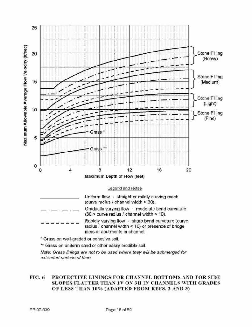
Use of desi--ji charts Figures 6 through 11 consist of charts to be used in selecting the appropriate lining type for know-n or assumed flow conditions and channel geometry. Figure 5 defines some of the nomenclature used in these charts .
The velocity referred to in Figures 6 and 7 is the mean or average velocity of w=ater flowing in the channel, that is, the flow quantity divided by the cross-sectional area of flow . The shape of the curves results from the fact that, as the channel depth increases, the ratio of the velocity at the channel boundaries to the average velocity decreases. The maxiilnml permissible flow velocity inllnledlately adjacent to the lllllng is given by the horizontal seglllents of the Curves intersectlllg the vei"tical axis . The maximum allowable flow velocity for a given stone size depends also on the flow conditions (uniform, gi -aduallyr varying or rapidly varying). These are determined by the curvature of the channel aligninlent and the presence of obstructions in the channel . Information is insufficient regarding the performance of grass linings under various flow conditions . It is reconlnnended that added protection in the form of stone filling be provided at bends and junctions in grass-lined channels.
EB 07-039
Page 16 of 59

TRAPEZOIDAL CHANNEL
C'R05S -SECTION
A TRIANGULAR CHANNEL Oanx sideslopes)
CROSS-SECTION
CHANNEL GRADE OR LONGITUDINAL SLOPE = 10%
SECTION A-A
FIG. 5
DEFINITIONS OF TERMS RELATING TO CHANNEL GEOMETRY
EB 07-039
Page 1 7 of 59
as
a 0
V
Q
0
~X ca
25
20
15
10
5
0 0
4
8
12
16
20 Maximum Depth of Flow (feet)
* Grass on well-graded or cohesive soil .
Legend and Notes
Uniform flow - straight or mildly curving reach (curve radius I channel width > 30) .
EB 07-039
Page 1 8 of 59
Gradually varying flow - moderate bend curvature (30 > curve radius I channel width > 10) . Rapidly varying flow - sharp bend curvature (curve radius / channel width < 10) or presence of bridge piers or abutments in channel.
* Grass on uniform sand or other easily erodible soil . Note: Grass linings are not to be used where they will be submerged for PXtPnrhP_rl nPrlrarhS of fimIa
Stone Filling (Heavy)
Stone Filling (Medium)
Stone Filling (Light)
Stone Filling (Fine)
FIG. 6
PROTECTIVE LININGS FOR CHANNEL BOTTOMS AND FOR SIDE SLOPES FLATTER THAN 1V ON 3H IN CHANNELS IVITH GRADES OF LESS THAN 18% (ADAPTED FROM REFS. 2 AND 3)
/ . toop
19 _
r '~
olo ~ .
/ --- - . . . . ._ .~ - . . ._ . . . _ . . -_ .__ . . . _. . .r__ .. :! ._ . .. . ._ . _ . . . . . .__ _ . . . . . . . .. :___ . . .. . .. . . . . . . . . . . . . . . . .. : .__ .
fr ~
. .' = Gras
Gras, '~*

.a
a
~X
25
20
15
10
5
0 0
4
8
12
16
20 Maximum Depth of Flow (feet)
* Grass on well-graded or cohesive soil . ** Grass on uniform sand or other easily erodible soil . Note: Grass linings are not to be used where they will be submerged for cvtcnrlcarl ncrinric of fimc
Legend and Notes
FIG. 7
PROTEC'TIV'E LININGS FOR SIDE SLOPES EQUAL TO OR STEEPER THAN 1ti' ON 3H IN CHANNELS WITH GRADES OF LESS THAN 10% (ADAPTED FROM REFS. 2 AND 3)
EB 07-039
Page 1 9 of 59
Uniform flow - straight or mildly curving reach (curve radius I channel width > 30) . Gradually varying flow - moderate bend curvature (30 > curve radius I channel width > 10) . Rapidly varying flow - sharp bend curvature (curve radius I channel width < 10) or presence of bridge piers or abutments in channel.
Stone Filling (Heavy)
Stone Filling (Medium)
Stone Filling (Light)
Stone Filling (Fine)
r
r ~- r
--- _ . . ..mar._ . . _ . _ . . . . _ . : - ------------ _ . ~ ~. . .~ . .�,. " r^ . ~~. .. . . . . _ . .
r
----------- _ .' - . .
le
- - - -______-
k2.~ ra a
. . .~Y"
.5. . ., . ._ . . . . . . . :. . . . . .. .-- . .. ._ ._ .. .. . . . . . . .. . . . . .. ._ . . . . . . . :. . . . ..--- . .. ._ ._ . . . . . . .. . . . . .. . . . . . . . . . . . .
:. . . . . . .-- . . . ._ ._ . .. . .

V
.a
.~I V
Q kw H as
100
0
10
0.1
_
10 20 30 40 50
Channel Grade in 1/6
FIG. 8
PROTECTIVE LININGS FOR TRAPEZOIDAL CHANNELS WITH GRADES->10%
EB 07-039
Page 20 of 59
--.- : NOTE : On a steep slope . a closed pipe drain -"it6 appropriate inlet and outlet eatment niav be more onomieal than a lined open annel .
Stone Filling (Heavy)
tome Filling (11edium)
tone Filling (Light)
Grass (on well-graded of cohesive Soil
Stone Filling (Fine) Grass (on uniform sand
or other easitV erodible soil)
--r~71

Grass (on uniform sand or other easily erodible spill
Stone Filling (Light) 10 20 30 40 50
Channel Grade in Q,.o
FIG. 9
PROTECTIVE LININGS FOR TRIANGULAR CHANNELS WITH GRADES > 10% AND SIDE SLOPES = IV ON 2H
EB 07-039
Page 21 of 59
DOTE : On a steep slope, a --: closed pipe drain with
_
appropriate inlet and outlet treatmeet may- be more economical than a lined open channel.
Stone Filling (Heavy)
_ ; -
-. Stone Filling (Medium)
Grass (on well-graded or cohesive sail)

1000
500
100
50
10
5
0.1 10
EB 07-039
Page 22 of 59
NOTE : On a steep slope ; a closed pipe drain with appropriate inlet and outlet treatment may- he more economical than a lined open channel.
Stone Filling (Heavy)
Stone Filling (14edium)
Grass (on v-ell-graded or cohesive sod)
Stone Filling (Light) Grass (on uniform sand
or other easily erodMe son)
20
30
40
50
Stone Filling (Fine) Channel Grade in o,-b
FIG. 10
PROTECTIVE LININGS FOR TRIANGULAR CHANNELS WITH GRADES > 10% AND SIDE SLOPES = IV ON =tH
-----------------
-_ -_;

FIG. 11
1000
EB 07-039
500f:
100
Stl
10
Channel Grade in q,,'o
Page 23 of 59
0.1 10 20 30 40 50
-NOTE: On a steep slope, a closed pipe drain with appropriate inlet and outlet treatment may he more econonucal than a lined open channel.
Stone Filling (Hea'vy)
Stone Filling (_Xledinm)
Grass (on well-graded or cohesive soil)
Stone Filling (Light)
Grass (on uniform sand or other easily erodihle soil)
Stone Filling (Fine)
PROTECTIVE LININGS FOR TRIANGULAR CHANNELS «'ITH GRADES > 10% AND SIDE SLOPES <_ 1V ON SH
-
- --- __ -- -t ._ - _- _- _-- - _ _ -.-- -_
_

Ill the case of channels A7ith grades of 10 °'o or steeper (Figures 8. 9, 10 and 11), the flow conditions are highly turbulent throughout, and the effect of channel curvature oil stone size can be neglected .
The relationship between maximum channel depth and the allowable average flow velocity represented by the curves shoNxTn in Figures 6 and 7 is valid for roughly triangular to trapezoidal channel cross-sections without pronounced breaks in the slope going fl'Om main chailnel to flood plain. If the flood plain is flat, compared to the inclination of the baths of the main channel, the velocity distribution will be considerably different than that 0i1 which Figures 6 and 7 are based. In this case, the channel cross-sectional area should be divided into separate mails channel and flood plain areas by imaginary vertical lines . The average flow quantit- y and velocity for each area can be computed knowing the total flow and the slope (S) for the entire stream and estimating Manning's n, and hydraulic radius (R) for each area separately .
Protection for a location subject to the high velocity maul channel flow should then be selected from Figures 6 and 7 using the average velocity ill the main channel . At locations well back on the flood plain, the type of protection can be selected based on the average velocity and the maxiinuin depth ill the flood plain section. Judgment may have to be used to decide which of these two cases is applicable .
Other considerations which influence the selection of a lining are discussed for various 00211111011
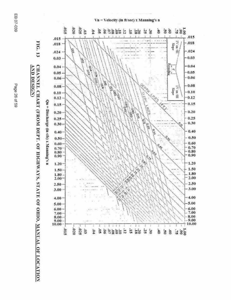
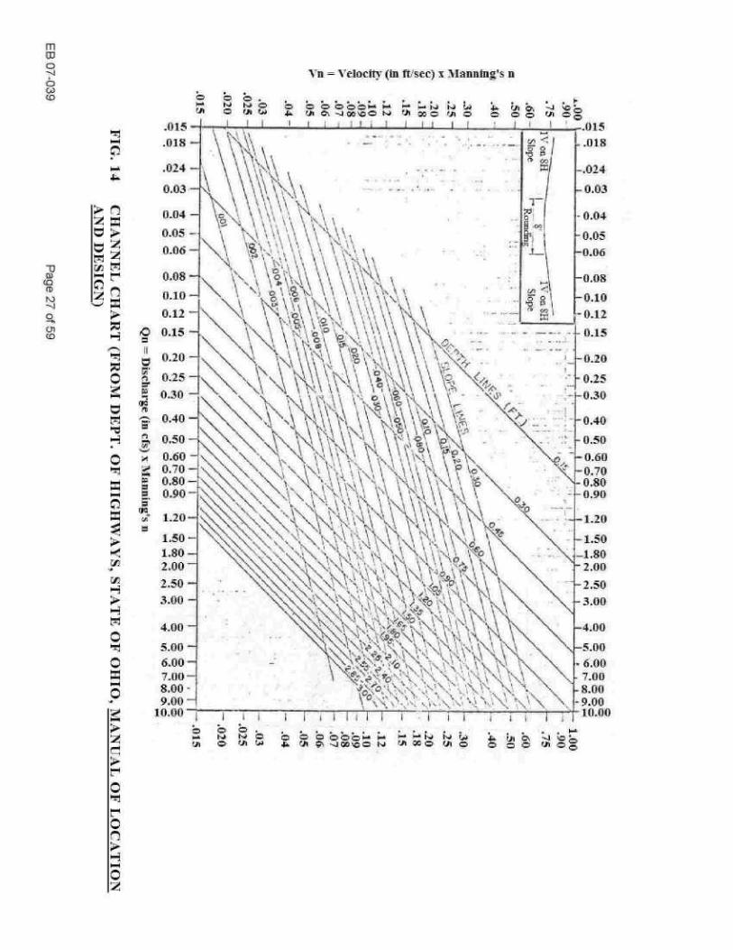
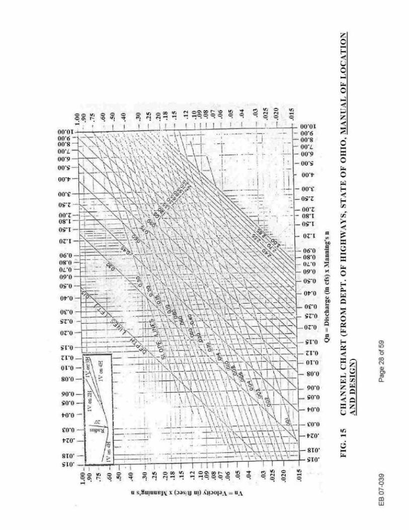
lining types subsequently . A chart relating the dimensions of theoretical stone shapes to their weight is plotted in Figure 12 as ail aid in evaluating the particle size distribution of stone filling and rip-rap materials . Figures 13, 14 and 15 are included to facilitate the design of small rounded triangular channels . For a known channel flow or discharge and a kno-vvin channel slope or grade, the depth and velocity of flow in the channel can be found . It should be noted that the discharge and velocity in these figures is multiplied by the coefficient of roughness (Manning's n) of the channel . Thus, these figures can be used regardless of the type of channel lining . Since the coefficient of roughness in grass lined channels is not constant, a trial and error procedure using Figures 13, 14 and 15 ill conjunction with Figure 16 is necessary when computing the flow velocity in a grass lined channel . The Appendix contains examples of this procedure .
EB 07-039
Page 24 of 59

d= 8 in (200 mm)
d= 6 in (150 mm)
d=15 in (400 mm)
d=12 in (300 mm)
.d=10 in (260 mm)
50 lbs (23 kg)
20 lbs (9 kg)
d=13 in (340 mm)
25 lbs (11 kg)
101bs (5 kg)
150 lbs (75 kg)
100 lbs (50 k9)
d=18 in (475 mm)
d=18 in (475 num)
d=15 in (400 mm)
Specified Teights and Sizes
600 lbs (300 kg)
300 lbs (150 hg)
Zd
d=15 in (400 mm)
d=12 in (300 mm)
d= 9 in (240 mm)
d= 23 in (600 mm)
d=18 in (475 mm)
d=15 in (400 mm)
K d
d= 27 in (700 mm)
d= 21 in (550 mm)
I,
d=17 in (440 mm)
40 lbs (18 kg) 10lbs(5k)
EB 07-039
Page 25 of 59
= 21 in (600 mm)
Approximate Shape
FIG. 12
STONE FILLING WEIGHT-SIZE CON`V'ERSION CHART
Differences in the specific gravity of stone do not affect the dimensions shown in this chart significantIv.
m 03
ffl
-0 co co (D t"i
2.50
3.00
4.00
5.00
Vn = Velocity (in Msec) x -Alannttig's n
:6 ;A ~ CD 0 0
6.00 -1
. I
.
-
- .
N
k*,% ', .
."
'. ti .' "
"'MI
~
tv"
\
-,
6.00 7 00-1
-900 10.00 lomo -
t- 11 l-h 6% Zj SO
C) rh 0
0
C 0
Q
0-4 (7)
J
y
y
O
O 0-4 O J
Y
r O r O y O
.011-1-1
.018-
.024
0.03
0.04-
0.05-
0.06-
C5 Id
6.00 7.00 8 .00 9.00
10 .00 -~ 0 o ~ t~ o
r~ C~ rJt W
O C
. .
. . h N
Fv O
O
O O O © r~ ~ ` Fd
~-'
F-~ td
N
Sri
O ul 0% -.I 00 ~G O W
f~
00 O
rA O
O
O O
f.1
O O
ti -n = Velocity (in ft,'see) s llannzn-a's n
i
i
t
u I
x°.
a©k ° 00c w
00 0
fit a
.6.00
~ 7 .00
8.00
9.00 10.00
m 03 0
O GJ O
n d y
r -o h r N
O
10 C,D y b
d
C
ri.+ A
b y
O w
%- ~
--1 . , -
46 , "
-%
- 7T-0
OT ,O X
Q) 80 ,0
_~
~
I
i
i
` ~ .~';"~;~ ~ ~1,~~~ ~' .
'
'~~~'~"
. ,,`o,,~, 1'-
,
90*0 .
i
I
~'~
~ .``' y 1.,1 ~ 'v
,~~,
t
r ,,`: .`
,~i
~
I
~
30*0 to*o
tzo
u S,tff!UUUIV X- (gas ; Jj U!) -Opop_%- = U-k
0001 1- 00'6 -00,8
18 co LU
5.3
Evaluation of various lining types 5.3.1
Grass fninLs Grass linings are suitable for applications where they will be exposed to periodic, relatively slow flow of water . They are commonly used in small roadside drainage channels carrying water intermittently, on the tipper parts of the banks of larger channels, and in the emergency spillways of small darns (Fig . 18) .
This type of lining has a pleasing appearance ; is economical and is not sut1ject to damage as a result of undermining or settlement of the supporting soils . A considerable length of time is required to establish an adequate grass ever starting from seed . Jute mesh and similar temporary protective materials provide only a minimum of protection against erosion (Fig . 19) . Drainage channels constructed of sod, held in place with pins or stakes, are least likely to be eroded during the early post-construction phase and are recommended for use in :
1)
easily erodible soils, 2) channels with a design flow near the maximum permissible for a grass lining, and 3) locations where the establislunent of a grass cover would require an excessive length of
time .
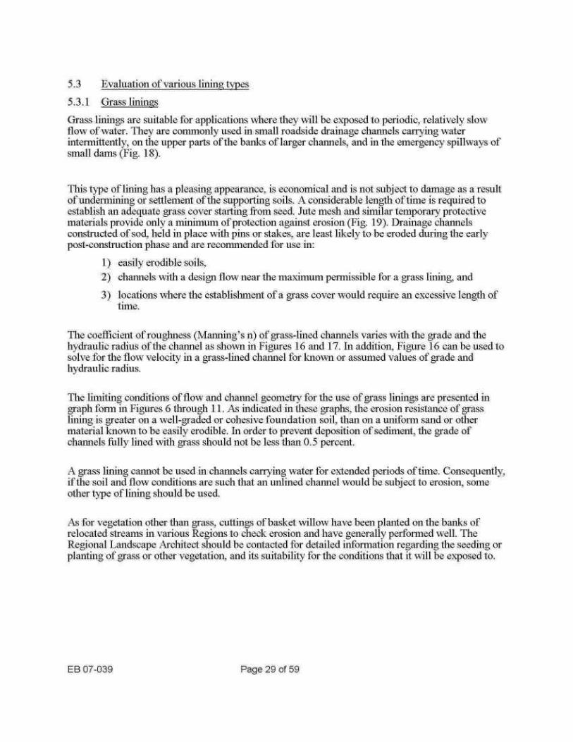
The coefficient of roughness (Malnlulg's n) of grass-lined chaimels varies with the grade and the hydraulic radius of the channel as sho«-n iii Figures 16 and 17 . In addition, Figure 16 can be used to solve for the flow velocity in a grass-lined channel for known or assumed values of made and hydraulic radius .
The lllllltlllg conditions, of flow and charlilel geQliletiy for the use of grass linings are presented in graph form in Figures 6 through 11 . As indicated in these graphs, the erosion resistance of grass lining is greater on a well-graded or cohesive foundation soil, than oil a uniform sand or other material known to be easily erodible . In order to prevent deposition of sediment, the grade of channels filly lined with grass should not be less than 0.5 percent .
A grass lining cannot be used in channels carrying water for extended periods of time . Consequently, if the soil and flow conditions are such that an unlined channel would be subject to erosion, some other type of lining should be used .
As for vegetation other than grass, cuttings of basket willow have been planted on the banks of relocated streams in various Regions to check erosion and have generally performed well . The Regional Landscape Architect should be contacted for detailed information regarding the seeding or planting of grass or other vegetation. and its suitability for the conditions that it will be exposed to .
EB 07-039
Page 29 of 59

cd 0 a
C
.3
EB 07-039
Page 30 of 59
i
-77
.5 .6 .7 .8 .9 1
1 .5
2 2.5 3 Hydraulic Radius, R, ft .
FIG. 16
SOLUTION OF THE MANNING FORl%ltTLA FOR GRASS-LINED CHANNELS RETARDANCE CLASS D (FROM "HANDBOOK OF CHANNEL DESIGN FOR SOIL AND WATER CONSERVATION", SCS-TP-61, REVISED 1954)
0
0 .
0 .
0.0
0.0
0 .0 0.1
0.2 0.30.40.50.60.s1
2 3 4 56 8 10
20
Product ofVelocity find Hsdraulfc Radius %-R. in sq.ft . per sec .
FIG. 17
MANNING'S n FOR GRASS LINED CHANNELS, RETARDANCE CLASS D
EB 07-039
Page 31 of 59
1 I
Conservation", SCS-TP-61, Revised 1954
"t 1~1 I ir~~'Nli
'

5.3.2
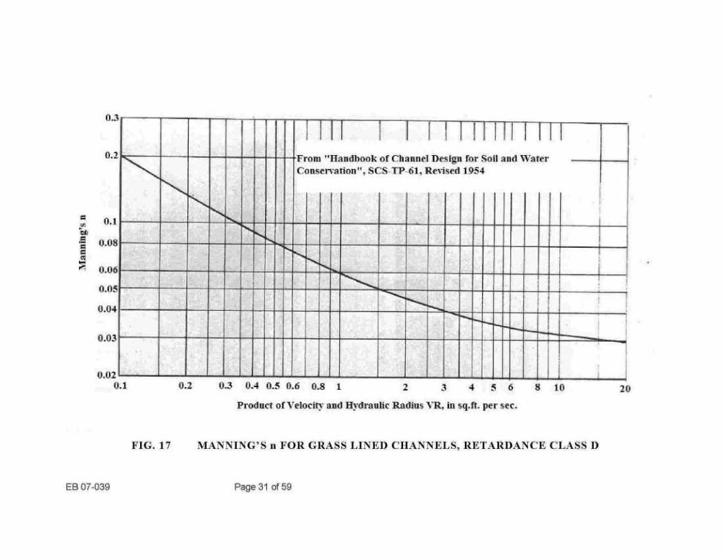
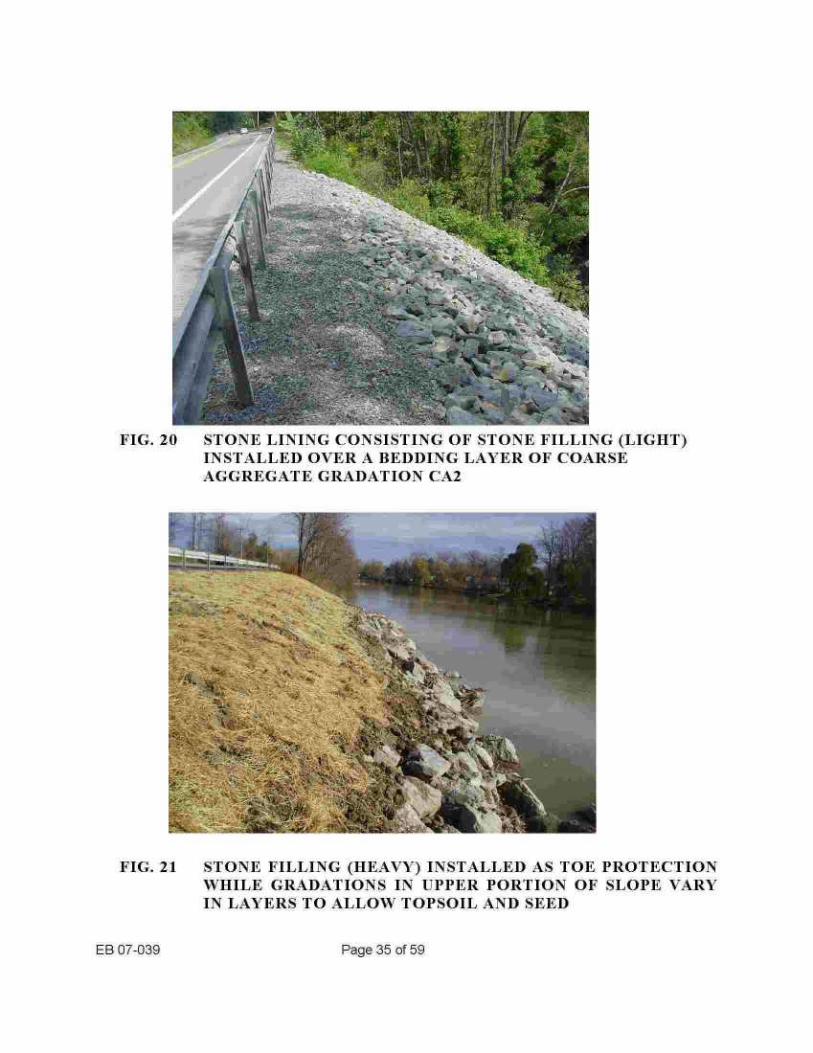
Dumped stone linings Dumped stone linings are considered to include all stone linings dumped or individually placed in such a manner that the stones resting on the foundation soil or bedding layer, support other stones (Fig . 20 and 21) . As a result, the lining consists of more than a single layer of stones, and the underlying material is not exposed if settlement takes place or individual stones are displaced by ice action . all additional advantage of this lining, under certain conditions, is its coarse surface texture which dissipates the energy of water flowhig over it, thus reducing its velocity .
There is a benefit in having a well-graded stone as lining material, with individual stones ranging from a size equal to the thickness of the liming dowel to one-inch spalls . This type of material forms its own filter that prevents the underlying filler materials from washing out through the lining. Experiments referred to in NCHRP Report 108, "Tentative Design Procedure for Rip-Rap-Lined Channels," HRB, 1970, indicate that a well-graded dumped stone finning can be considerably thinner than a uniformly graded dumped stone lining and still provide equivalent protection against washing out of the underlying material.
The following tabulation lists the minimum permissible mean particle sizes (d,o), assuming spherical stone, and the roughness coefficients (elf alming's ii) for the four types of stone filling mentioned in this manual :
The erosion resistance of a dumped stone lining depends oil the average size of the stone and on channel geometry . Figures 6 through 11 should be used to determine the stone size required to provide adequate erosion resistance for the design flow and proposed channel geometry .
It is not known how ice action (impacts, shoving, etc.) affects the various sizes of stone filling . Local experience may show that, il order to avoid displacement by moving ice, the stone size has to be increased above the values given by figures 6 through 11 . In canals and some locations in navigable streams, the erosive effect due to passing ships or barges may be more critical than that of the current or of wind-caused moves. Inn such cases, previous experience should govern the selection of a suitable size of stone filling for erosion protection .
EB 07-039
Page 32 of 59
Stone Filling Type d_,O M a n il l n g' s 11
Stone Filling (Fine) 3 in . (75 nml) 0.031 Stone Filling (Light) 6 in. (150 mm) 0.035
Stone Filling (Medium) 13 in . (3501n1n) 0.040 Stone Filling (Heavy) 23 in . (600 llllnl) 0.0

It is recommended that dumped stone linings not be designed thiluner than the thicknesses given in the following tabulation :
Smaller thicknesses would not be realistic in view of the specified particle sizes of the lining materials and the natural variability of rock particle sizes .
If stones haying a diameter greater than the reconuinended minimum lining thickness are specified, the lining thickness should be increased to equal the maximum stone diameter . It should be kept ul mind that the ability of a dumped stone lining to resist erosion is not increased by increasllng the thickness of the lining. This resistance can be increased only by increasing the average stone size or by flattening the slope . In the absence of an adequate filter layer, increasing the lining thickness does reduce the probability of underlying finer material washing out through voids in the lining.
Post-construction maintenance of dumped stone linings can be accomplished relatively easily by rearranging displaced stone with a backhoe or gradall . or by dumping additional stone where the lining has been disrupted . If it is seen that the stones originally used in the lining were moved by the water, larger size stone should be used in rehabilitation work
EB 07-039
Page 33 of 59
Stonne Filling Type ~-
Illiniinui,,Thiciuiess Stone Filling (Fine) 9 in. (22-5 mini) Stone Filling (Light) 12 in. (300 inn)
Stone Filling (Medium) 18 in. (450 nnm) Stone Filling (Heavy) 30 in. (750 rnm)

Y i =3, W
a~ W Jj R
FIG. 18 GRASS LINED S«%ALE
FIG. 19 INSTALLATION OF EROSION CONTROL MAT FOR STABILIZATION OF GRASS LINED SNI'ALE
EB 07-039
Page 34 of 59
EB 07-039
Page 35 of 59
s kky
FIG. 20
STONE LINING CONSISTING OF STONE FILLING (LIGHT) INSTALLED OVER A BEDDING LAYER OF COARSE AGGREGATE GRADATION CA2
FIG. 21
STONE FILLING (HEAVY) INSTALLED AS TOE PROTECTION WHILE GRADATIONS IN UPPER PORTION OF SLOPE N`ARY IN LAYERS TO ALLOW TOPSOIL AND SEED

5.3.3
Paved or grouted linings
This group of linings includes those constructed of Portland cement concrete, asphalt concrete, grouted rip-rap (Fig. 22) or grouted stone paving. These linings are comparatively smooth, and water flows over them ̀-,Fill a high velocity producing the following undesirable results :
1) Plucking action of water at cracks and joints may remove underlying supporting soil. 2) Unless adequate protection is provided at the downstream end, the high-speed flow tends
to erode a plunge pool that may work its way back and undermine the lining .
Because of their rigidity, paved and grouted linings are unable to adjust to settlement or local loss of the supporting soil . Consequently, they are subject to undermining that becomes progressively more severe, frequently resulting in a complete failure (Fig . 23).
There are conditions, however, under which a paved lining may be the most economical alternative. The following precautions in the design and construction of paved linings will increase the chances for a successful installation :
1) Use a paved lining oiily in soil conditions where settlement or lateral movement of the foundation soil is not likely to occur.
2) Use a channel grade not steeper than 10 percent. 3) Do not use a channel grade flatter than 0.35 percent i n order to avoid deposition of
sediment. 4) Compact loose foundation soils. 5) Provide an underdrain system for major channniels where hydrostatic uplift forces are
anticipated. Do not use weep holes unless foundation is rock or compact till, or provisions are made to prevent the washing out of the supporting soil .
6) Depress channel so that the top of the lining is below the surrounding ground surface .
7) Place strip of sod, at least 1 ft . (0 .3 m) wide, on each side adjacent to the paved lining.
8) Do not use contraction or expansion joints .
9) t%se continuous reinforcement extending through all constrlictionjoints .
10) Increase the height of lining on the outside of bends and opposite connecting chantiels .
11) Collect and control flow at the upstream end of the lining in order to prevent under mining by water flowing adjacent to the channel.
12) Provide cutoffs below ground surface at upstream and downstream ends of lining.
13) Protect against erosion at downstream end of lining as recommended in 6 . PROTECTION AT CLTLX'ERT AND PANTED CH_-NNEL OUTLETS.
EB 07-039
Page 36 of 59

r M-A v~ itar .
~n -
5.3.4
Dry rip-rap and tagged concrete EB 07-039
Page 37 of 59
FIG. 23
FAILURE OF PORTLAND CEMENT CONCRETE CHANNEL LINING
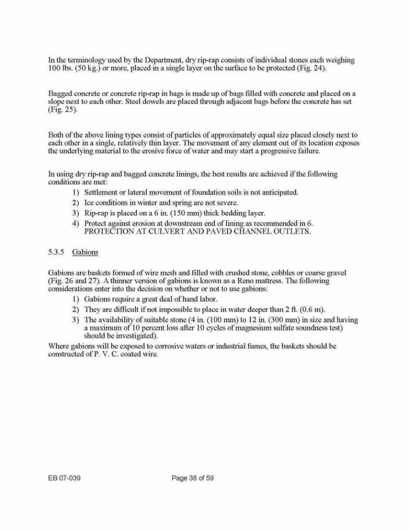
In the tennntnology used by the Department, dry rip-rap consists of individual stones each wet 100 lbs . (50 kg . )`or more, placed in a single layer on the surface to be protected (Fig. 24) .
In using dry rip-rap and bagged concrete linings, the best results are achieved if the following conditions are met :
1) Settlement or lateral movement of foundation soils is not anticipated. 2) Ice conditions in winter and spring are not severe . 3)
Rip-rap is placed on a 6 in . (150 tmni) thick bedding layer. 4) Protect against erosion at downstream end of lining as recommended in 6 .
PROTECTION AT Ct1LVERT AND PAVED CHANNEL OUTLETS .
5.3.5 Gahions
EB 07-039
Page 38 of 59
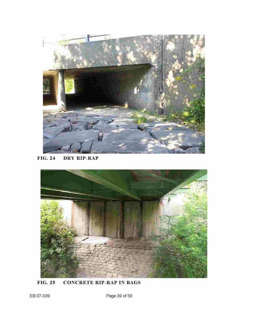
Bagged concrete or concrete rip-rap in hags is trade tip of bags filled with concrete and placed on a slope next to each other . Steel dowels are placed through adjacent bags before the concrete has set (Fig . 25).
Both of the above lining types consist of particles of approximately equal size placed closely next to each other in a single, relatively thin layer. The nno-\7ennent of any element out of its location exposes the underlying material to the erosive force of water and may start a progressive failure .
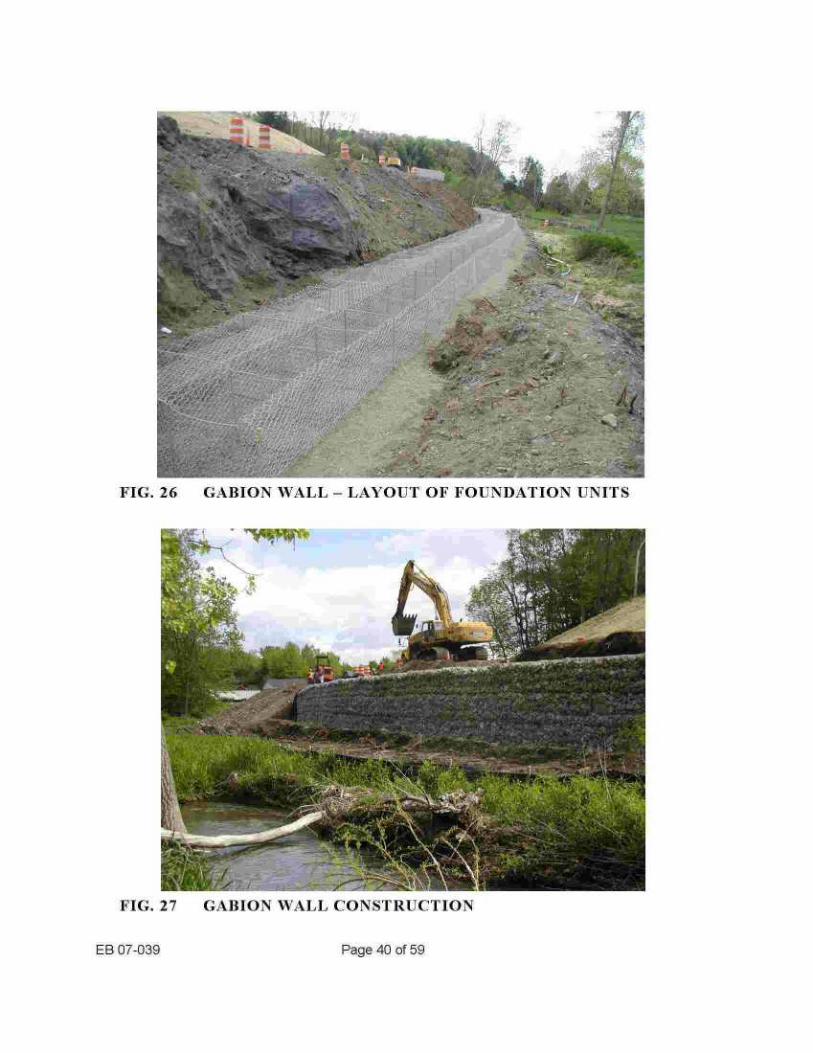
Gahions are baskets fotnned of wire mesh and tilled with crushed stone, cobbles or coarse ravel (Fig . 26 and 27) . A thinner version of gabions is known as a Reno mattress . The following considerations enter into the decision on whether or not to use gabions :
ring
1) Gahions recu, ire a great deal of hand labor . 2) They are difficult if not impossible to place in water deeper than 2 ft . (0.6 m) . 3) The availability of suitable stone (4 in . (100 min) to 12 in. (300 nun) in size and having
a maximum of 10 percent loss after 10 cycles of magnesium sulfate soundness test) should be investigated) .
NN'here gabions will be exposed to corrosive waters or industrial fumes, the baskets should be constructed of P . V . C . coated wire .
r
FIG. 24
DRY RIP-RAP
EB 07-03 9
Page 39 of 59
FIG. 25
CONCRETE RIP-RAP IN BAGS
6 ,
FIG. 26
GABION WALL - LAYOUT OF FOUNDATION UNITS
FIG. 27
GABION WALL CONSTRUCTION
EB 07-039
Page 40 of 59
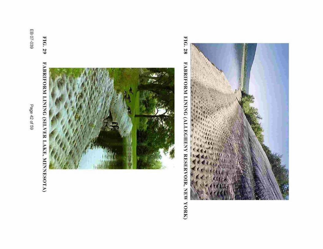
5.3.6 Fabrifonr Fabriformi i s a patented lining, ,NTNNv .fabi-ifomi l .coin, consisting of two sheets of nylon fabric fastened together at regular intervals and filled with Portland cement grout (Figs . 28 and 29) . A Fabriform lining can be placed by a diver to a considerable depth under water.
The nylon fabric deteriorates under prolonged elposure to sunlight . In southern United States under conditions of intense sunlight, complete disintegration of the upper sheet has taken place in less than five years after construction. Protective coatings can be used to reduce the rate of deterioration . The distributors state that, even in installations where the entire upper part of the nylon cover has disintegrated, the solidified rout has remained in place and that . if the outer nylon cover is tone by ice or abrasive bed load, the Fabrifonn blanket as a whole will retrain intact .
Fabriform has been used with good success by the Department . Specifications, typical sections, and cost information are available from the Design Division.
5.3.7
Soil cement Soil cement facings have been used for protection against wave erosion on several dams, «r\A.r\v .cement.org,''`vater/`dauis sc.a~p . Sandy soil is required to produce acceptable soil cement. A manual entitled Soil-Cement Slope Protection published by the Portland Cement Association is a comprehensive reference on all aspects of the use of soil cement for erosion protection .
5.3.8
Closed pipe drains Though not a type of lining, closed pipe drains are mentioned here because on steep slopes they may be more economical than dumped stone or other linings . Closed pipe drains have the advantage of not being subject to overtopping, but they can be undermined by e=ater flowing along the boundary between the pipe and the back-fill material . Therefore, the inlet should be constructed so as to channel all low into the pipe . A cutoff should be provided at the inlet, and foundation and back fili material should be thoroughly compacted . Erosion protection in accordance with 6. PROTECTION AT CULVERT AND PAVED CHANNEL OUTLETS should be provided at the downstream end.
EB 07-03 9
Page 41 of 59
U A1
(D
N 0
Cn CO
0

5.4
Rectuired extent of linings 5.4.1
Stream channel linings Most failures of protective hnrngs can be attributed to inadequate extent of the luring and subsequent undermining. In order to prevent this type of failure, a lining should be terminated at stable features or extended at its lateral limits to such a depth that undermining will not occur .
The upper limit of dumped stone protective blankets should generally be at the design high water level. In wide rivers some freeboard should be provided to protect against wave actiotL Grass cover established above the upper limit of the stone will normally provide adequate protection against flood flows.
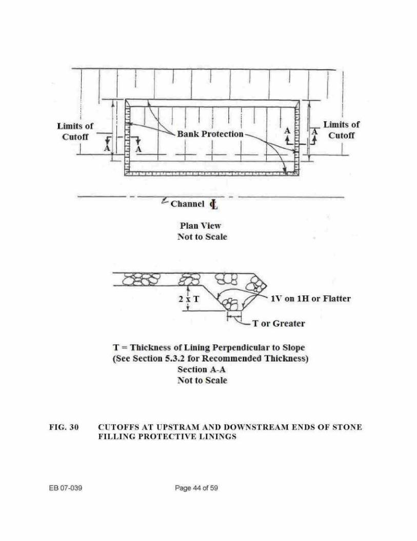
Blanket type linings protecting the banks of sizable streams should be extended to bedrock outcrops; natural slopes deriving erosion resistance from well-established vegetation, or other stable features . If this is not feasible, cutoffs should be provided at the upstream and downstream ends of the protective blanket as shown in Figure 30 for stone filling protective linings .
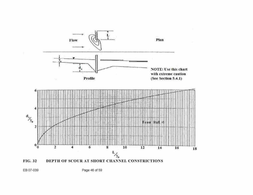
Maximum protection against erosion at the toe is obtained if the protective lining is continued to bedrock or other erosion-resistant stratum . However, it is seldom feasible to do so. _us an alternate, where the channel is composed of sand and/or silt, bank protection may be terminated at a depth of at least 5 It . (1 .5 m) below the streambed . The depth should be increased at the outside banks of sharp bends and at other locations where scour is likely to occur, and the liming extended to the anticipated depth of scour . tTnfoitunately, the computation of the depth of scorer is a problem that has, in spite of numerous attempts, so far escaped solution. Figures 28 and 29 are based on data obtained from model tests relating depth of scour to the dimensions of channel constrictions .
A long channel constriction (Fig. 31) corresponds to the practical case of an embankment built roughly parallel to and in or adjacent to a stream . A short constriction (Fig . 32) occurs at many locations where a highway crosses a stream . The relationships shown in Figures 31 and 32 should be regarded oiAy as rough guides to j udgment when attempting to predict scour depths . The actual scour depths may be considerably smaller or greater depending on such factors as : the type of stream-bed material, amount of bed load carried by the stream, channel geometry, and others . When evaluating the possibility of scour, it should be noted that all ernbanknnent or a structure may not encroach on a stream while it is carrying normal flow . but may do so during floods when the stream flows iii a wider channel .
..
-At locations ha-,rung erodible channel conditions, where it is not practical to dig a trench and continue the protective blanket below- the streambed. a stone toe provides material that will fall into a scour hole that may develop and in this way extend the blanket . Recommended toe dllnensions are shown in Figure 33. If a paved or grouted rip-rap lining is used in a relatively narrow channel, the entire width of the channel should be lined . If it is not feasible to do so, some other type of haling should generally be selected .
EB 07-039
Page 43 of 59
Plan View Not to Scale
EB 07-039
Page 44 of 59
T = Thickness of Lining, Perpendicular to Slope (See Section 5.3 .2 for Recommended Thickness)
Section A-A Not to Scale
FIG. 34
CUTOFFS AT UPSTRAM AND DO«+'NSTREAM ENDS OF STONE FILLING PROTECTIVE LININGS

Plan
Profile
NOTE; Use this chart mith extreme caution (See Section 5 .4.1)
II II I II
~~E
Il~e~s~~
1I~iun ee ~ Y'EB2
FIG. 31
DEPTH OF SCOUR IN LONG CHANNEL CONSTRICTIONS
EB 07-039
Page 45 of 59
Flow
r -
Profile
Plan
NOTE- Use this chart with extreme caution (See Section 5.4.1)
Ir
nn~~u~~owv~
. ma IIIIS S
ii
III~I I 9
1 2 4 -- 6 8 10 12 14 I6 n

EB 07039
Page 47 of 59
*A = 1 .5 x T or 3 ft., whichever is greater . **B = 5 ft . in straight reaches ; 10 ft . at outside banks of
bends ; the anticipated depth of scour in constrictions .
FIG. 33
RECOMMENDED DIMENSIONS FOR STONE TOES IN ERODIBLE CHANNELS

5.4.2
Small roadside drainage channels In the case of small roadside or down slope drainage channels, erosion starts most often at the downstream end of the channel lining, if the flow discharges onto natural ground or into an unlined ditch . It is important to make sure that the slope of the ditch or the natural ground downstream of the lining is sufficiently flat so that the discharged flow of water causes no erosion. In addition, a vertical cutoff and a dumped stone apron., a plunge pool lined with stone, or some other type of energy dissipater should be provided at the discharge end of channels carrying flow with a high velocity head (for example, channels having Portland cement concrete, asphalt concrete, hand placed dry or grouted rip-rap, or similar smooth linings) . Additional lining height should be provided on the outside of bends and at channel junctions .
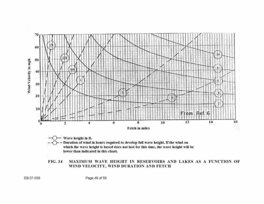
5.5 Protection against«have action Wave action can erode the unprotected slopes of embankments built adjacent to reservoirs, lakes, or wide rivers . The maximum height of waves that can be expected to occur at a location depends on the wind velocity . the fetch (or length of open water over which the wind acts) and the duration of the wind . If these factors are known, the maximum wave height can be estimated fi-om Figure 34.
Stone filling (medium) can be used as protection against wave action at locations where the wave height is expected to be between 1 ft . (0.3 m) and 4 ft . (1 .2 m) . Stone filling (heavy) should be used where wave heights of 4 ft . (1 .2 m) to 10 ft . (3 .0 m) are anticipated . Wave protection can be reduced on slopes flatter than 1 V on 4H. Slopes of inland bodies of water having all inclination of 1 V on 8H or flatter can be protected by a 12 in . (300 nun) layer of stone filling (fine) regardless of wave height .
Wave protection should extend from 1 .5 times the wave height above nigh water level to 5 ft . (1 .5 tin) below low water level . In the case of flood-control reservoirs, where high water level is maintained only a short period of time and vegetation can be established on the slopes, other wave protection may not be necessary . The design of seashore wave protection should be based on local experience .
EB 07-039
Page 48 of 59
70
60
50
40
:;0
20
10
0 0
EB 07-039
---
- Wave height in ft . -
- Duration of iiind in hours required to develop full wave height. If the w,fnd on which the wave height is based does not last for this time, the wave height will he lower than indicated in this- chart.
FIG. 34
MAXIMUM WAVE HEIGHT IN RESERVOIRS AND LAKES AS A FUNCTION OF WIND VELOCITY . WIND DURATION AND FETCH
Page 49 of 59
Fetch in miles
6
ti 1 .
il u ~ ~ I
m 1U)
I
vu r
p ~~ln
8 10 14
6 . PROTECTION AT CULVERT AND PAVED CHANNEL OUTLETS
6.1
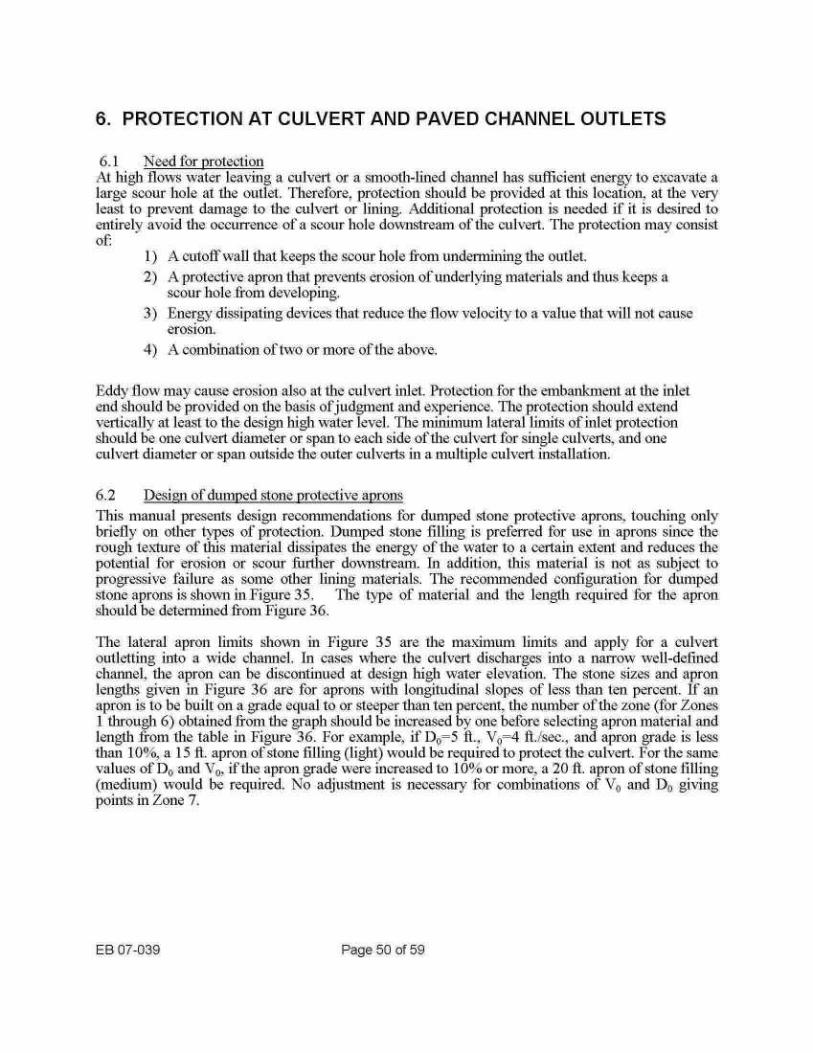
Need for protection At high flows water leaving a culvert or a smooth-lined channel has sufficient energy to excavate a large scour hole at the outlet . Therefore, protection should be provided at this location, at the very least to prevent damage to the culvert or lining . Additional protection is needed if it is desired to entirely avoid the occurrence of a scour hole downstream. of the culvert . The protection may consist of.
1) A cutoff wall that keeps the scour hole from undermining the outlet . 2) A protective apron that prevents erosion of underlying materials and thus keeps a
scour hole from developing. 3) Energy dissipating devices that reduce the flow velocity to a value that will not cause
erosion . 4) A combination of two or more of the above .
Eddy flow may cause erosion also at the culvert inlet . Protection for the embankment at the inlet end should be provided on the basis of judgment and experience . The protection should extend vertically at least to the design high water level . The minimum lateral limits of liilet protection should be one culvert diameter or span to each side of the culvert for single culverts, and one culvert diameter or span. outside the outer culverts iii a multiple culvert installation .
6.2
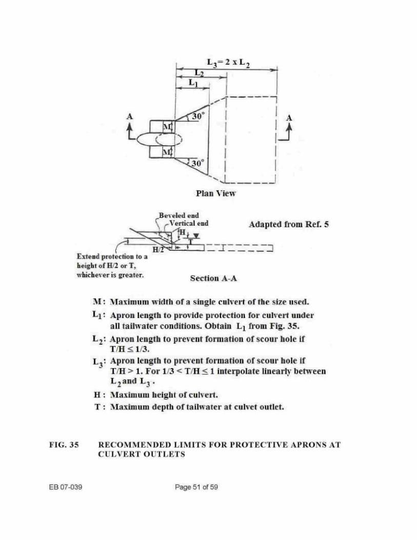
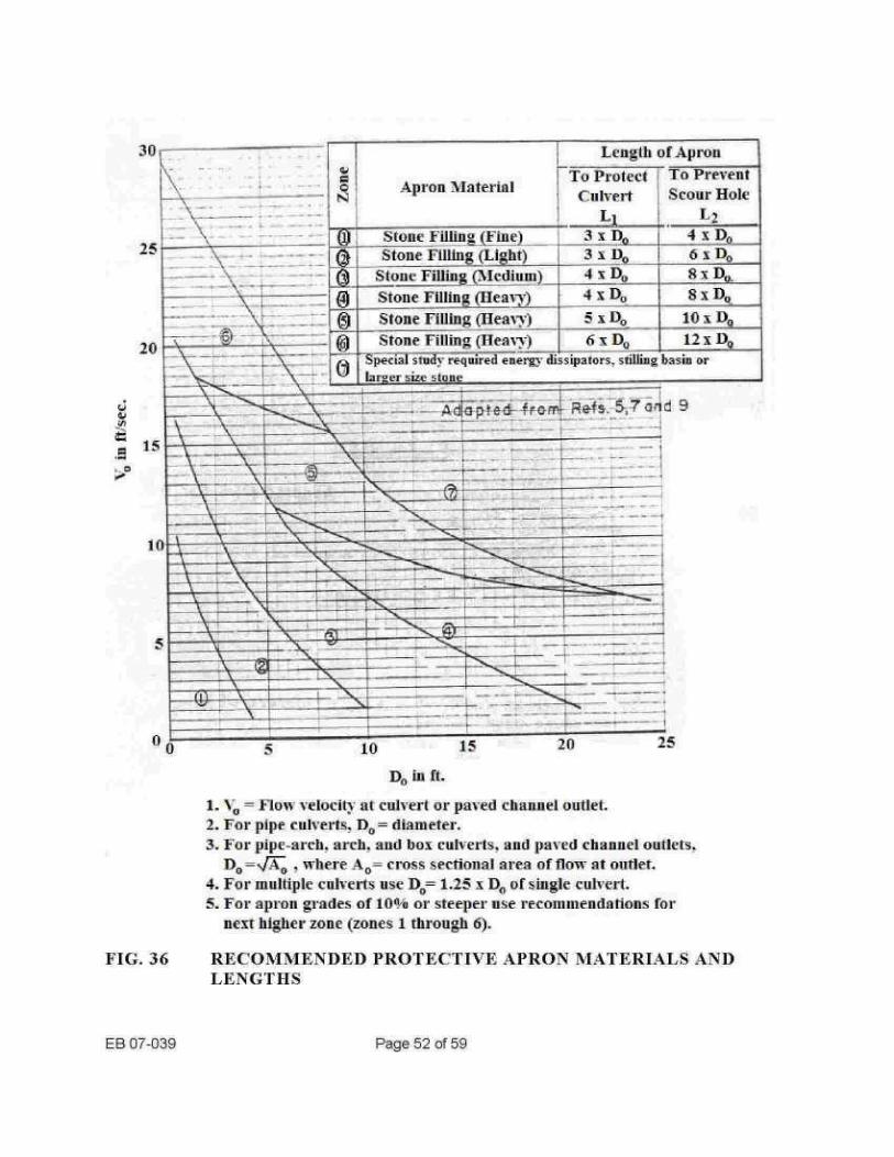
Design of dumped stone protective aprons This manual presents design reconunendations for dumped stone protective aprons . touching only briefly on other types of protection. Dumped stone filling is preferred for use in aprons since the rough texture of thus material dissipates the energy of the water to a certain extent and reduces the potential for erosion or scour further doNvnstream. In addition, this material is not as sut1ject to progressive failure as some other lining materials . The recommended configuration for dumped stone aprons is shown in Figure 35 . The type of material and the length required for the apron should be determined from Figure 36 .
The lateral apron limits shown in Figure 35 are the maximum. limits and apply for a culvert outletting into a wide channel . In cases where the culvert discharges into a narrow well-defined channel, the apron can be discontinued at design high water elevation. The stone sizes and apron lengths given in Figure 36 are for aprons with longitudinal slopes of less than ten percent . If an apron is to be built on a grade equal to or steeper than ten percent, the number of the zone (for Zones I trough 6) obtained from the graph should be increased by one before selecting apron material and length f1-om the table in Figure 36 . For example, if D(,=5 fl ., VO=4 ff./sec ., and apron grade is less than 10°-0. a 15 ft. apron of stone filling (light) would be required to protect the culvert . For the same values of Dt, and V,0 , if the apron grade were increased to 10% or more, a 20 ff. apron of stone tilling (medium) would he required . No adjustment is necessary for combinations of Vo and D,, giving points iii Zone 7.
EB 07-039
Page 50 of 59
c Extend protection to a height of H-2 or TT whichever is greater.
L .and L3 .
Beveled end I 1'ertical end
Plan " iew
Section
H : :1laximum height of culvert.
EB 07-039
Page 5 1 of 59
T : Maximum depth of tailwater at culvet outlet .
Adapted from Ref.
NI : tiiaximum width of a single culvert of the size used . L1
Apron length to provide protection for culvert under all tailwater conditions. Obtain L1 from Fig. 35 .
L .~ : Apron length to prevent formation of scour bole if T;]F1 < 1/3.
L3 : Apron length to prevent formation of scour hole if T!H > 1 . For 1,-3 < :'H<_1 interpolate linearly between
FIG. 31
RECOMMENDED LIMITS FOR PROTECTIVE APRONS AT CULVERT OUTLETS
Length of Apron
To Protect
To Prevent Culvert
Scour Hole Ll i L, . _
Stone Yilling (Fine) 3 x j Q0
s P,0 Stone Filling (Light)
3 s Do 6 x Do, Stone Filling (Medium)-
4 X Do - _
8 x Do_ Stone Filling (Heavy)
4 x D, o 8 x Do
Stone Filling (Heavy)
5X00 10 Stone Filling (Heavy)
6 s Do_
12 1) cial stndv required energy dissipators . stilling basin or
larger size Stone
or en ,
1 . '%o = Flow velocity at culvert or paved channel outlet. 2 . For pipe culverts. D o = diameter . 3 . For pipe-arch, arch, and box culverts, and paved channel outlets .
DO =,TTO , where Aa= cross sectional area of floes- at outlet. 4. For multiple culverts use Do 1 .25 s D,, of single culvert. 5 . For apron grades of IW o or steeper use recommendations for
next higher zone (zones 1 through 6).
FIG. 36
RECOMMENDED PROTECTIVE APRON MATERIALS AND LENGTHS
EB 07-039
Page 52 of 59
_
__ ;
~.dFR4d 4 .4FrL r-ef. ̂ 5, ? on d 9

The thickness of the stone lining in an apron should be equal to or greater than shown in the following tabulation :
These thicknesses are greater than those reconunended for other applications because the concentrated flow froin the culvert rearranges the stone to some extent .
6.3
Other types of protection In some cases an energy dissipater may have to be used at a culvert outlet because erosion protection by means of a dumped stone apron would require stone of excessive size . Ill other cases a stilling basin or an energy dissipater may be more economical than an apron . The following three are among references that can be used as an aid in the design of energy dissipaters and stilling basins :
1) Engineering Monograph No - 25, "Hydraulic Design of Stilling Basins and Energy Dissipaters", U. S . Dept . of Interior. Bureau of Reclamation, 1963.
2) MacDonald, T. C . "Energy Dissipaters for Large Culverts", American Society ot'Civil Engineers, Journal of the Hydraulics Division, Vol . 9_5, No. HY6, pp. 1941-1958, November 1969.
3) Thorson et al ., "Design Criteria for Controlled Scour and Energy Dissipation at Culvert Outlets using Rock and a Sill", IIRB Annual Meeting, January 1971 .
Channel protection downstream of the, energy dissipater can generally be designed in accordance with 5 . DESIGN OF PROTECTIVE LININGS .
In soils containing particles of coarse gravel size and larger, protection other than a shallow cutoff wall may not be necessary for the culvert if a scour hole can be tolerated . The formation of a scour hole induces the energy of the flow and the size of the particles in the scour hole increases because the tiller materials are washed out first . As a result, the, scour stabilizes, leaving a stone,-lined plunge pool or slillilg basin that acts as an energy dissipater . The depth of the plunge pool is a function of the culvert flow and the gradation of the soil .
EB 07-039
Page 53 of 59
Stone Lining Thickness Stone Filling (Fuse) 12 ul. (300 nlm) Stone Filling (Light) 18 in . (450 mnl)
Stone Filling (Medium) 24 in . (600 null) Stone, Fillilg (Heavy) 36 in . (900 nun)

Model tests performed by the Corps of Engineers (Ref: 5) indicate that, if a cutoff wall alone is used to protect a culvert from undennuning in uniform fuse sand, the required depth of the cutoff wall is as follows :
1) One and one-half culvert diameters, when the tail water is below raid-height of the culvert .
2) One-half the culvert diameter, when the tail water is above mid-height of the culvert .
It is reconnnnended, therefore, that additional protection besides a cutoff wall be used in soils other than Coarse-grained glacial tills or outwash, unless a high tail water condition is maintained permanently .
EB 07-039
Page 54 of 59
7. FILTER OR BEDDING LAYERS
7.1
The need for filter or bedding, lavers Water seeping through a soil induces seepage pressures, which tend to move the soil particles in the direction of seepage . If the soil does not have sufficient cohesion and the individual soil particles are not sufficiently heavy to resist the seepage force . they will be displaced. This may result in erosion, starting at a. point where the soil particles are not held ill place by overlying materials . If the soil contains a sufficient proportion of particles that are too large for the seepage forces to trove, a natural filter layer maybe built up as some of the fine particles are washed out and erosion tends to cease . In the absence of coarse particles, erosion may work its way progressively back . Examples of thus occurrence are some types of cut slope sloughs and piping under or through dams. Criteria have been developed for the determination of the required grain size of a granular filter material, which when placed over a soil with a known grain size distribution, will prevent erosion of the soil . As an alternate to a granular material, geotextile bedding. consisting of a fabric that has pores permitting water to pass but retaining most of the soil particles. is often used .
Water flowing over a protective lining that has openings ; such as stone filling or dry rip-rap, can pluck out underlying soil particles if the openings are large compared to the size of the soil particles and if the water velocity is sufficiently high. Ian the case of dumped stone linings, the water velocity at the bottom of the lining is comparatively low because of the rough texture and the thickness of the lining. Therefore, strict observation of the usual filter criteria in determining the need for and the required gradation of a granular filter or bedding laver would be overconset-vative and uneconomical. Elceptiot>,s, where filter criteria should be strictly observed, are the presence of moderate to severe wave action or of a steep hydraulic gradient in the foundation soil leading to high seepage pressures to the direction of the lining .
For the purpose of evaluating the need for a bedding layer, soils may be divided into two groups : 1) Erodible soils - Non-plastic soils consisting predominantly_ of sand and silt with less than
15 percent, by weight, of particles retained on the 1/4 in . (6.3 nun) sieve . Erodible soils are usually found as alluvium, beach__ delta and dune deposits as well as non-plastic lake sediments .
2) Non-erodible soils - Soils containing at least 15 percent, by weight, of particles retained on the i'i in. (6.3 mm) sieve and/or having some plasticity .
Local experience may indicate that some soils, which, based on the above criteria, would belong to the second group, present erosion problems in the field . These soils should be treated as erodible soils . The Regional Geotechnical Engineer should be contacted for advice regarding the erodibility of soils at a particular site .
EB 07-039
Page 55 of 59
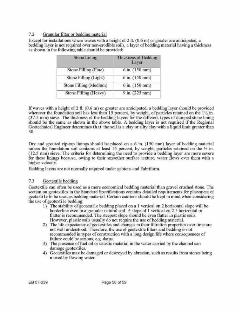
7.2
Granular filter or bedding material Except for installations where waves with a height of 2 fl. (0.6 in) or greater are anticipated, a bedding laver is not required over non-erodible soils, a laver of bedding material having a thickness as shown in the following table should be provided :
7.3
Geotex-tile bedding
If waves with a height of 2 t . (0.6 in) or greater are anticipated, a bedding layer should be provided wherever the foundation soil has less than 15 percent, by weight, of particles retained on the 1 in. (37.5 nun) sieve . The thickness of the bedding layers for the different types of dumped stone liming should be the sane as shown in the above table . a bedding layer is not required if the Regional Geoteclunical Engineer determines that the soil is a clay or silty clay with a liquid limit greater than 30 .
Dry and grouted rip-rap linings should be placed on a 6 in . (150 nun) layer of bedding material unless the foundation soil contains at least 15 percent, by weight, particles retained on the ~ .~ in. (12.5 nun) sieve . The criteria for determining the need to provide a bedding layer are more severe for these linings because, owing to their smoother surface texture, water flo`vs over them with a higher- velocity . Bedding layers are not normally required under gabions and Fabriforrn .
Geotextile can omen be used as a more economical bedding material than gravel crushed stone . The section on geotextiles in the Standard Specifications contains detailed requirements for placement of geotexti 1 e to be used as bedding material . Certain cautions should be kept in mind when considering the use of geotextile bedding :
1) The stability of geotextile bedding placed on a 1 vertical on 2 horizontal slope will be borderline even in a granular natural soil . a slope of 1 vertical on 2 .5 horizontal or flatter is recommended. The steepest slope should be even flatter in plastic soils . However, plastic soils usually do not require the use of bedding material .
2) The life expectancy of geotextiles and changes in their filtration properties over time are not well understood . Therefore, the use of geotextile filters and bedding is not recorninended in types of construction with a long design life where consequences of failure could be serious, e.g. ans.
3) The presence of fuel oil or caustic material iii the water carried by the channel can damage geotextiles .
4) Geotextiles may be damaged or destroyed by abrasion, such as results from stones being moved by flowing water.
EB 07-039
Page 56 of 59
Stone Lining Thickness of Bedding Laver
Stone Filling (Fine) 6 in . (150 nun) Stone Filling (Light) 6 in. (150 nnli)
Stone Filling (Xledlum) 6 in. (150 min) Stone Filling (Heavy) 9 in . (225 min)
5) Geotextile is not recommended as bedding for dry or grouted rip-rap since. to achieve the objective of a smooth face, adjacent stones may have to be embedded in the bedding material to different depths .
Back-fill material finer than coarse gravel can infiltrate the voids between the stones in a gabion wall . Tl1is occurrence can be prevented economically by covering the stone-filled gabions with geotextile before placing backfill against or over them .
EB 07-039
Page 57 of 59

REFERENCES
l .
Hydraulic Engineering Circular No. 6 . Design of Roadside Drainage Channels, U. S . Department of Commerce, Bureau of Public Roads, April 1962 . Hydraulic Engineering Circular No. 11, Design of Riprap Revetment . U.S . Department of Transportation, Federal Highway Administration, Publication No. FHWA-IP-89-016, March 1989 . McWhorter, J . C., et al ., Erosion Control Criteria for Drainage Channels : Mississippi State University, March, 1968 . NCHRP Synthesis of Highway Practice No. 5, Scour at Bridge Waterways, HRB. 1970 . Research Report H-70-2, Erosion and Rip-Rap Requirements at Culvert and Storm Drain Outlets, U. S . Army' Engineers Waterways Experimental Station, Vicksburg, Mississippi, January, 1970 .
6 .
Sherard, J . L ., et al ., Earth and Earth-Rock Dams, Jolm Whey and Sons, Inc ., 1963 . 7 .
Simons. D.B., et al ., Flood Protection at Culvert Outlets, Wyoming State Highway Department, 1970 .
8 .
State of California, Department of Public Works, Division of Highways, Bank and Shore Protection rn California Highway Practice, November, 1960 .
9 .
Thorson, D.A., et al ., Desic,, rl Criteria for Controlled Scour and Energy Dissipation at Culvert Outlets tTsmg Rock and a Sill, HRB Aruiual Meeting. January, 1971 .
EB 07-039
Page 58 of 59

APPENDIX
Sample Problems
EB 07039
Page 59 of 59


Problem :
Available inforination :
Solution :
Sample Problem No . 1 (US Customary Units)
A highway embankment will be constructed on the fled plain of a river . Design a protective lilting for the embankment . A plan view of the area is shown.
l .
Flood plain soil is a fine silty sand . 2 .
Design flood flow i-94 00 ft 3/see . 3 .
Cross-sectional area of flow at design flood (after embanlallent construction is 1300 ft'- . No appreciable difference between slope of maul channel banks and flood plain .
4 .
Maximum depth of river at design flood is 12 ft . Average slope of water sill-ace at design flood is 0 .002 .
5 .
Embanlunent side slopes are 1 V on 2H . 6 .
Embankment material is a fine sand.
Average velocity of flow = Q/A = 9400i' 13 00 = 7 .2 ft/sec .
Refer to plan view . The ratio of the radius of curvature of the channel to channel width at design flow is less than 10 . by inspection . Therefore, the curves for rapidly varying flow in Fig . 7 should be used. For a maximum flow depth of 12 ft ., the maximum allowable average flow velocity for stone tilling (fine) is 6.7 ft/sec . Consequently, stone filling (light) is the required protection .
As the flow spreads out over the flood plain, at a certain depth the flow velocity is so low that no protection other than grass is required. This depth and the points at which the stone filling can be ended are found as follows .
If the channel bottom is comparatively flat and the channel is wide, the hydraulic radius, R, will be approximately equal to the depth of flow . For a small depth, from Figure 6, grass will provide adequate erosion protection for an easily erodible soil if the velocity of flow is not more than 2 ft/sec . From Fig . 16, for a slope of 0.002 and a velocity of 2 ft/sec, the hydraulic radius, R is 1 .4 ft . No embankment protection, other than grass, is necessary where the depth of flow is less than 1 .4 ft . A stone fllirlg (light) protective lining is provided, therefore, only between C/L Station A and C/L Station B. A typical section of the lining is shown in Section A-A. Normally, excavated material could be used to backfill the trench, the cross-section of which is triangle KLM. In this case, however, because of the location on the outside of a bend, additional protection against undermining of the lining has been obtained by using stone filling (light) also in KLM. A fine sand is an easily erodible soil . Therefore, a 6 inch layer of bedding material has been provided . Since the flow velocities at Station A and Station B Fill be comparatively low, no cut-offs normal to the direction of flow have been provided.
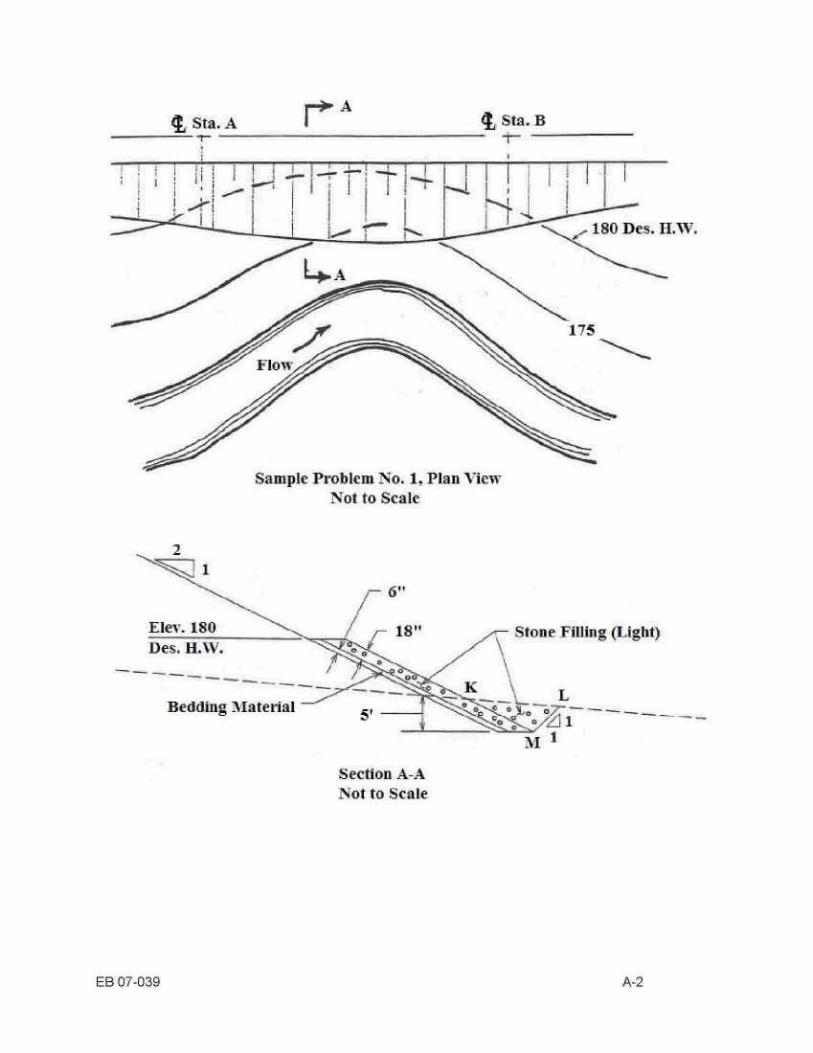
EB 07-039
2
Elev. 180 Des . H.W.
Bedding Alaterial
Sample Problem No. 1, Plat View Not to Scale
A 'Not to Scale
I Sta. B
A-2
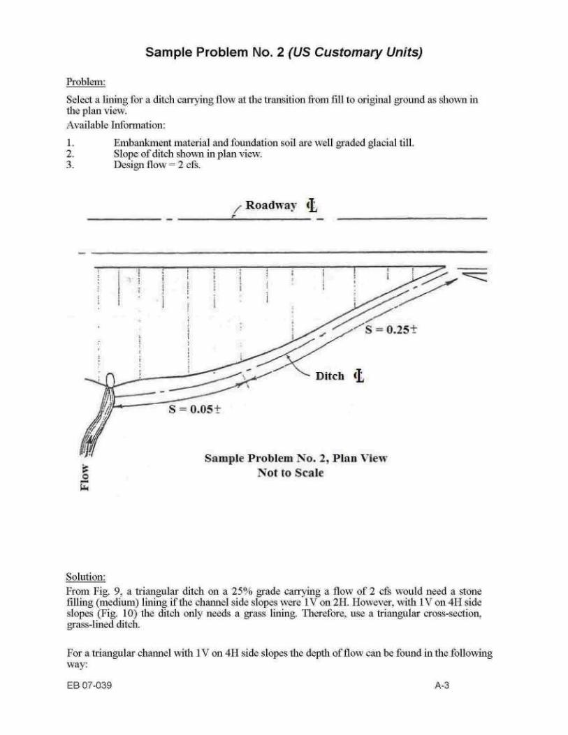
Problem:
Select a lining for a ditch carrying flow at the transition from fill to original ground as shown in the plan view. Available Information:
'nlhai
inent material and foundation soil aro well
dod ala~i',l ti ._
t,
~ f t,
6 c, t 2.
Slope of ditch shoxxvn in plan view . Design flo`A7 = 2 cfs.
Solution :
Sample Problem No . 2 (US Customary Units)
S = 0.(15±
Roadway
a Not to Scale w
"S = 0.25±
Sample Problem No . 2, Plan 'k -iew
From Fig. 9 a triangular ditch on a 2_511,0' grade carrying a flow of 2 cfs would need a stone filling (medium) lining if the channel side slopes were 1 V on 2H. However, with 1 V on 4H side slopes (Fig. 10) the ditch only needs a grass lining . Therefore, use a triangular cross-section, grass-lined ditch.
For a triangular channel with 1 V on 4H side slopes the depth of flow can he found in the following way:
EB 07-039
A-3

1 .
Assume a value of n, say 0.05 . 2 .
Enter Fig . 13 with Qn = 2 x 0 .05 = 0 .1 . 3 .
For Qn = 0.1 and slope = 0.25, Vn = 0.2 . 4 .
From Fig . 16 for slope = 0 .25 and velocity = Vrvn = 0.2/0.05 = 4 ft/sec, n = 0 .063 . 5 .
Try n=0.07 . 6 .
From Fig . 13 for Qn = 2 x 0.07 = 0.14 and slope = 0.25, Vn = 0 .22 . 7 .
From Fig . 16 for slope = 0 .25 and velocity = 0.22/0 .07 = 3.1 ft/sec. n = 0.7+ . 8 .
From Fig . 13 the depth of flow corresponding to Qn = 0 .14 and Vin = 0.22 is approximately 0.22 ft .
The depth of the rounded portion of the channnel shown ill Fig . 13 is found to be 0.25 $. by geometry . Therefore, a 4 fl. wide rounded channel is adequate . Sod is selected for use instead of seeding protected by jute mesh, because of the lower probability of erosion before the grass cover is established.
The lining for the lower section of the ditch, which is on a > °,'6 grade selected as follows (a triangular ditch with 1 V on 4H side slopes will be used) : l .
~kssume a value of n, say 0.10 (grass lining) . 2 .
Enter Fig . 13 with Qn = 2 x 0 .10 = 0 .20 . 3 .
For Qn = 0.20 and slope = 0.05, Vn = 0 .14 . 4 .
From Fig . 16 for slope = 0 .05 and velocity = Vn/n = 0.14'0.10 = 1 .4 ft/sec, n = 0 .095±. From Fig . 13 the depth of flow corresponding to Q = 0 .20 and Vn = 0.14 is approximately 0.40 fl .
6 .
Since the grade of the ditch is less than 10%, Fig . 6 is used to select the lining material . The bend in the aliginment of the channel is not particularly severe . Therefore, the velocity is increased by a factor of 1 . 5 when selecting the lining material for the outside of the bend . The increased velocity is 2.1 -ft/sec . and a grass lining is adequate .
The width of channel required for the computed 0.40 fl . depth is 4+ (0 .40-0.25)(4)(2) = 5.2 fl ., say 6 fl .
Because the curve in alignment is gradual and because a grass liming is not subject to damage by undermining, an increase in the height of the lining on the outside of the curve is not considered necessary . A short vertical curve should, however, be provided as a transition between the 25°'o and 5% ditch sections.
EB 07-039
A-4

Problem :
Design a protective apron to prevent undermining at the outlet of the three 72 inch diameter steel structure plate pipe culverts shown in Plan View A.
Available Information : 1 .
Foundation soil is a well-graded sand and gravel. 2 .
Culverts discharge into broad flat area so that low tail water conditions will prevail . 3 .
Longitudinal slope of apron at culvert outlet is less than 10°-0 . 4 .
Velocity of flow at culvert outlet is 8 f1- sec .
Solution :
Sample Problem No . 3 (US Customary Units)
For nniltiple culverts Do = 1 .25 x pipe diameter = 1 .25 x 6 = 7 .5 ft . From Fig . 36 for V" = S II/sec . and Do = 7 .5 ft ., use stone tilling (medium) and apron length Lt = 4 x Do = 30 ft . The size of stone tilling obtained fi-om Fig . 36 does not have to be increased since the longitudinal slope of the apron is less than 100 0. The area where the culverts outlet is flat . Therefore, the full lateral apron dimensions shown in Fig. 35 will apply, that is, the apron will not be discontinued laterally at a location where the bank of the channel reaches design high water elevation . The limits of the protection designed for the culverts are shown in Plan View B and Section A-A.
m
I
II
II
I
r) r)I Sample Problem No. 3 . Plan View
Not to Scale
EB o7-039
A-5
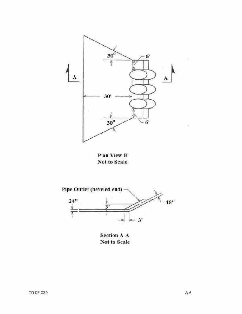
EB of-039
Plan View B Not to Scale
Pipe Outlet (beveled end) -
Section A-A Not to Scale
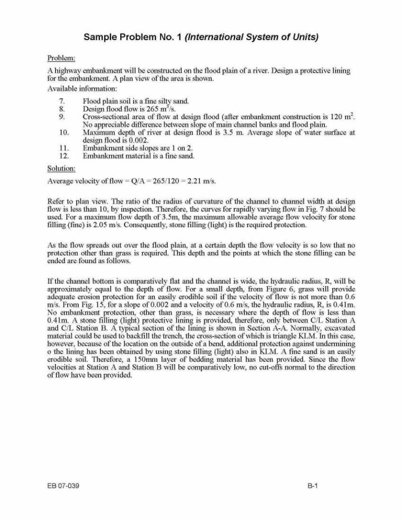
Problem :
Available inforination :
Solution :
Sample Problem No . 1 (International System of Units)
A highway embankment will he constructed on the fled plain of a river . Design a protective lining for the embankment . A plan view of the area is shown.
7 .
Flood plain soil is a fine silty sand . 8 .
Design flood flow is 265 nn'/s . 9 .
Cross-sectional area of flow at design flood (after embanlanent construction is 120 m'. No appreciable difference between slope of maul channel banks and flood plain .
10 .
Maximum depth of river at design flood is 3 .5 ni. Average slope of water surface at design flood is 0 .002 .
11 .
Embanlunnent side slopes are 1 on 2 . 12 .
Embanlanent material is a fine sand.
Average velocity of flow = Q/A = 265/120 = 2.21 m/s .
Refer to plan view . The ratio of the radius of curvature of the channel to channel width at design flow is less than 10, by inspection . Therefore, the curves for rapidly varying flow in Fig . 7 should be used. For a maximum flow depth of 3.5m, the maximum allowable average flow velocity for stone filling (fine) is 2.05 m/s . Consequently . stone filling (light) is the required protection .
A ,, the flow spreads out over the flood plain, at a certain depth the flow velocity is so low that no protection other than grass is required. This depth and the points at which the stone tilling can be ended are found as follows .
If the channel bottom is comparatively flat and the channel is wide, the hydraulic radius, R, will be approminately equal to the depth of flow . For a small depth, from Figure 6, grass will provide adequate erosion protection for an easily erodible soil if the velocity of flow is not more than 0.6 m/s . From Fig . 15, for a slope of 0.002 and a velocity of 0.6 ni/s, the hydraulic radius, R is 0.41111 . No embankment protection . other than grass, is necessary where the depth of flow is less than 0.41m. A stone filling (light) protective lining is provided, therefore, only between C/L Station A and C/L Station B. A typical section of the lining is shown in Section A-A. Normally, excavated material could be used to backfrll the trench, the cross-section of which is triangle KLM. In this case, however, because of the location on the outside of a bend, additional protection against undermining o the lining has been obtained by using stone filling (light) also in KLM. A fine sand is an easily erodible soil. Therefore, a 150mn1 layer of bedding material has been provided . Since the floe' velocities at Station A and Station B will be comparatively low, no cut-ofd's normal to the direction of flow have been provided.

E iet-. 55 Des. H.W.
Bedding I'Iateriai
Sample Problem No. 1, Plat View Not to Scale
l
Section A-A riot to Scale
it Sta. s
EB of-039
B-2

Problem :
Select a lining for a ditch carrying flow at the transition form fill to original ground as shown in the plan view. Available Information : 1 .
Embankment material and foundation soil are well graded glacial till . 2 .
Slope of ditch sho'~Nn in plan view . 3 .
Design flo`A7 = 0 . 08 m3 ~s .
s
Solution :
Sample Problem No . 2 (International System of Units)
f
/Roadway
r
©
Not to Scale r
Sample Problem No . 2, Plan View
From Fig . 9, a triangular ditch on a 20°,o grade carrying a flow of 0.08 mils would need a stone tilling (medium) lining if the chaiulel side slopes were 1 on 2 . However, with 1 on 4 side slopes (Fig . 10) the ditch only needs a grass lining . Therefore, use a triangular cross-section, grass-lined ditch .
..
For a triangular channel with 1 on 4 side slopes the depth of flow can be found in the following way: 1 .
Assume a value of n, say 0.05 . 2 .
Enter Fig . 13 with Qn = 0.08 10.05 = 0 . 004 . For Qn = 0. 004 and slope = 0 .20, Vn = 0 - 065.
EB 07-039
B-3
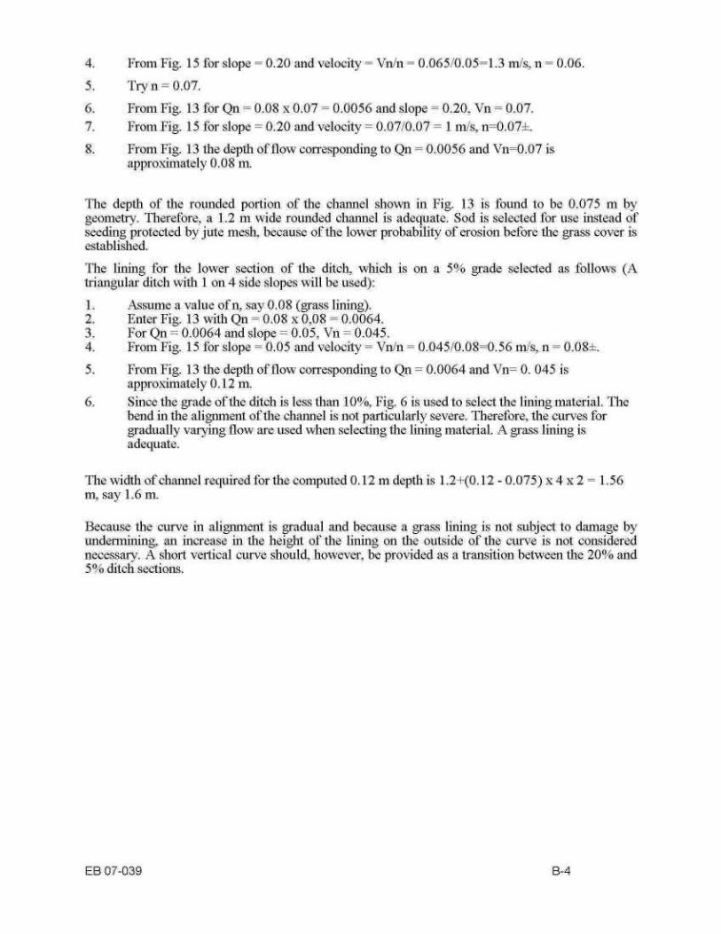
The depth of the rounded portion of the channel shown in Fig. 13 is found to be 0.075 m by geometiy . Therefore, a 1 .2 m wide rounded channel is adequate . Sod is selected for use instead of seeding protected by jute mesh, because of the lower probability of erosion before the grass cover is established. _
.
The linning for the lower section of the ditch, which is on a 5°10 grade selected as follows (A triangular ditch with 1 on 4 side slopes will he used):
1 .
Assume a value of n, say 0.08 (grass lining) . 2.
Enter Fig. 13 with Qn = 0.08 x 0,08 = 0.0064. 3.
For Qn = 0.0064 and slope = 0.05, Vn = 0.045 . 4.
From Fig. 15 for slope = 0 .05 and velocity = Vn/n = 0.045/0.08=0.56 inn/s, n = 0.08± .
5.
From Fig. 13 the depth of flow corresponding to Qn = 0.0064 and Vin= 0 . 045 is approximately 0.12 m. Since the grade of the ditch is less than 10°'0, Fig. 6 is used to select the lining material . The vend in the alignment of the channel is not particularly severe . Therefore, the curves for gradually varying flow are used when selecting the lining material . A grass lining is adequate .
The width of channel required for the computed 0.12 rn depth is 1 .2+(0.12 - 0 .075) x 4 x 2 = l . 56 m, say 1 .6 m.
Because the. curve in alignrnnent is gradual and because a grass lining is not subject to damage by undermining, an increase Hl the height of the. lining on the outside of the, curve is not considered necessary . A short vertical curve should, however, be provided as a transition between the 20% and
ditch sections .
EB 07-039
B-4
4. From Fig. 15 for slope = 0.20 and velocity = Vnin = 0.065;0.05=1 .3 n-./s, n = 0.06.
5. Try n = 0.07.
6. From Fig. 13 for Qn = 0.08 x 0.07 = 0.0056 and slope = 0.20, Vn = 0.07. 7. From Fig. 15 for slope = 0.20 and velocity = 0.07/0 .07 = 1 nils, n=0.07± .
From Fig. 13 the depth of flow corresponding to Qn = 0.0056 and Vtn=0 .07 is approximately 0 .08 nn.

Problem : Design a protective apron to prevent undennining at the outlet of the three 1800 nun diameter steel structure plate pipe culverts shown in Plan View A.
Available Information : 1 .
Foundation soil is a well-graded sand and gravel. 2 .
Culverts discharge into broad flat area so that low taihvater conditions will prevail . 3 .
Longitudinal slope of apron at culvert outlet is less than 10°-0 . 4 .
Velocitv of flow at culvert outlet is 2.4 nvs .
Solution :
Sample Problem No. 3 (International System of Units)
For multiple culverts Do = 1 .25 x pipe diameter = 1 .25 x 1 800 mm = 2.25 m. From Fig . 33 for V,' = 2.4 this and Do = 2 .25 m. use stone felting (iuedium) and apron length Li = 4 x Do = 9 m. The size of stone filling obtained from Fig . 33 does not have to be increased since the longitudinal slope of the apron is less than 10"-0 . The area where the culverts outlet is flat . Therefore, the full lateral apron dimensions shown in Fig. 32 NAAl apply, that is, the apron will not be discontinued laterally at a location where the bank of the channel reaches design high water elevation . The limits of the protection designed for the culverts are shown ill Plait View B and Section A-A.
Sample Problem No . 3, Plan View A Not to Scale
EB 07-039
B-5

mlu 006
a~ .aS of josz
V-V ualpas
cam 006
(pua pa1aaaq) 1ajjn0 adi j
alu3S of jo'c g _aal_k uujd
6CQ- LO 83