Embed Size (px)
Citation preview

@EJ> Banana PI User Manual
Banana PI U ser Manual
<Version: V2.0 >
1

® Banana PI User Manual
Banana PI is the open source hardware platform which published to assistant the
Elastos.org open so urce OS, Banana PI M1 is the dual core Android 4.2 product
which more better than the Raspbeny Pi.
Banana Pi series run Android,Debian linux,Ubuntu linux, Raspbeny Pi imange and
cubieboard imange.
Elastos coordinate multi CUP to fi:om the family cloud entirnment which based on the
"software/hardware service"
Banana PI hardware: 1 Ghz ARM7 dual-c01·e processor, 1GB DDR3 SDRAM,
Banana PI with Gigabit ethernet port, SATA Socket. It can run with Android 4.2.2
smoothly. The size ofBanana PI M1like the credit card, it can easily run with the
game it support 1080P high defmition video output, the GPIO compatible with
Raspberry Pi and can run the ROM Image directly
Hardware specification
CPU A20 ARM Cortex™-A7 Dual-C01·e
GPU
Memory (SDRAM)
Onboard Storage
Onboard Network
ARM Mali400MP2Complies with OpenGL ES 2.011.1
1GB DDR3 (shared with GPU)
SD (Max. 64GB) 1 MMC card slot UP to 2T on 2.5 SATA disk
10/10011000 Ethernet RJ45 ,optional WIFI
Video Input A CSI input connector allows for the connection of a designed camera module
Video Outputs
HDMI, CVBS , LVDS/RGB
Audio Output 3.5 mm Jack and HDMI
Power 5 volt via MicroUSB(DC In Only) and/or MicroUSB (OTG)
So urce
USB 2.0 Ports
Buttons
2 ( direct from Allwinner A20 chip)
Reset button: Next to MicroUSB connector Power button: Next to Reset button Boot button (Optional): Behind HDMI connector
2
@PP Banana PI User Manual
GPI0(2X13) GPIO,UART,I2C bus,SPI bus with two chip selects, pm CAN bus,ADC,PWM,+3.3v,+5v,ground.
LED Power Key & RT45
Remote IR (Optional)
OS Android 4.2,Firefox OS and Linux etc. OS
Interface defmition
Product size 92 mm x 60mm
Weight 48g
working temperature -15~ 7 5 ·e range
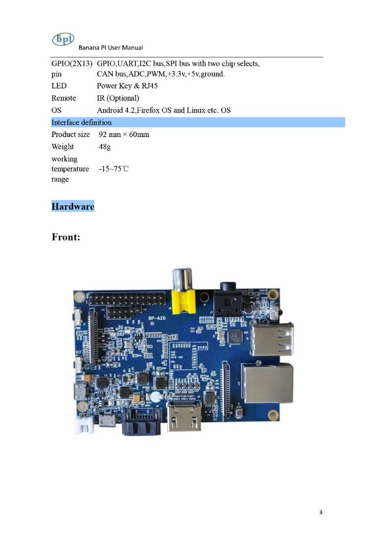
Hardware
Front:
3

® Banana PI User Manual
Back:
Interface
GPIO HEAOERS
POWER STATUS LEOS
OSI OTSP!AY CONNEa'OR
SDCARDSLOT ( 8ACK OF BOARD)
USBOTG
POWER
..,...,-' MJCRO USB POWER ( 5V lA OC)
RCA VTEDO OUT lRRECElVER
( AUDIO OUT
/ r US82.0
ETHERNET OUT
CSl CONNEa'OR CAMERA
4

® Banana PI User Manual
Hardware connect sketch map
•' •' .. ti DI J.t tiYI
Sc:rMn
uneS!
I.JSB port ~"'""""ilt::ua~
TFT toud1 Kr~n
OSI
,Audio out¡wt
SPJUU powtr
SO card ·Cb:ss 2,4.6,10~>2 •G8 .l71UU
UAftf CortHI
•",,_ '•, GPlO
S

® Banana PI User Manual
Use method
Step 1: Get what you need
First time to enjoy your Banana Pi, you need at least the accessories in the table below. No.
1
2a
2b
3
4
S
6
7
ltem
SD card
HDMI(Full sized) toHDMI / DVI
lead
A V video lead
Keyboard and
mouse
Ethernet cable!USB
WiFi(Optional)
Micro USB power adapter
Audio lead (Optional)
Mobile Hard disk (Optional)
•
•
•
•
• •
•
•
•
Minimu recommended specification & notes
Minimum size 4Gb; class 4 (the class indicates how fast the card is). We recommend using branded SD cards as they are
more reliable.
HDMI to HDMI lead (for HD TVs and monitors with HDMI input). OR HDMI to DVI lead (for monitors with DVI input).
A standard AV video lead to connect to your analogue display ifyou are not using the HDMI output.
Any standard USB keyboard and mouse should work. Keyboards or mi ce that take a lot of power fi:om the USB ports, however, may need a powered USB hub. This may include sorne wireless devices.
Networking is optional, although it makes updating and getting new software for your Banana Pi much easier.
A good quality, micro USB power supply that can provide at least 700mA at 5Vis essential. Many mobile phone chargers are suitable---check the label on the plug.
• You can choose a 3.5mmjack audio led to connect to audio port to get stereo audio.
• You can choose to connect a mobile hard disk to SATA p01t to store more files.
6

@eP Banana PI User Manual
HDMI to HDMI lead HDMI to DVI lead A V video lead
SD card Micro USB power adapter
Step 2: Download the relevant Image file:
Please visit our webmaster: www.banana-pi.com to download image, banana pian image can be download form this web.
Step3: Prepare your SD card for the Banana Pi
In order to enjoy your Banana Pi, you will need to instan an Operating System (OS)
onto an SD card. Instructions below win teach you how to write an OS image to your
SD card under Windows and Linux.
l . Insert your SD card into your computer. The size of SD should be larger than
the OS image size, generan y 4GB or greater.
2. Format the SD card.
Windows:
1. Download the a SD card format tool such as SD Formatter fi:om
https://www.sdcard.org/downloads/formatter 4/eula windows/
n. Unzip the download file and run the setup.exe to instan the tool on
your machine.
m. In the "Options" menu, set "FORMAT TYPE" option to QUICK,
"FORMAT SIZE ADWSTMENT" option to "ON".
7

® Banana PI User Manual
1 for ... 1,... ct ... AIIOIIho<Sota ................ ~ ....... ~-,.,.. s~· ....... " .XC:
1 SO. SOtte<r<lSO~ l_.,. *""'-' ol 50-JC.li.C
Mr.ii
s'"., 1 n 08 """"" w..~ PlJ:iOVfm
r..-~~ ~~ OOle("~RMI\T. f01>.14ATSIU A"O.JUSnt(Nn)fF
Option Setting
FORMAT TYPE (.._Q_UIO __ K ____ __,• ]
FORMAT SJZE f ] AOJUSTMENT .._O_N _____ __,•
Cancel
IV. Check that the SD card you inserted matches the one selected by the
Too l.
v. Click the "Format" button.
Linux:
v1. Runfdisk -l command to check the SD card node.
vn. Run sudo [disk ldevlsdx command to delete all partition of SD card.
vm. Run mkfs -t vfat ldevlsdx command to format the entire SD card as
FAT.
(x should be replaced according to your SD card node)
3. Download the OS image from Download district.
4. Unzip the download file to get the OS image.
Windows: Right click on the file and choose "Extract all".
Linux: Run unzip [downloaded filename] command.
8
® Banana PI User Manual
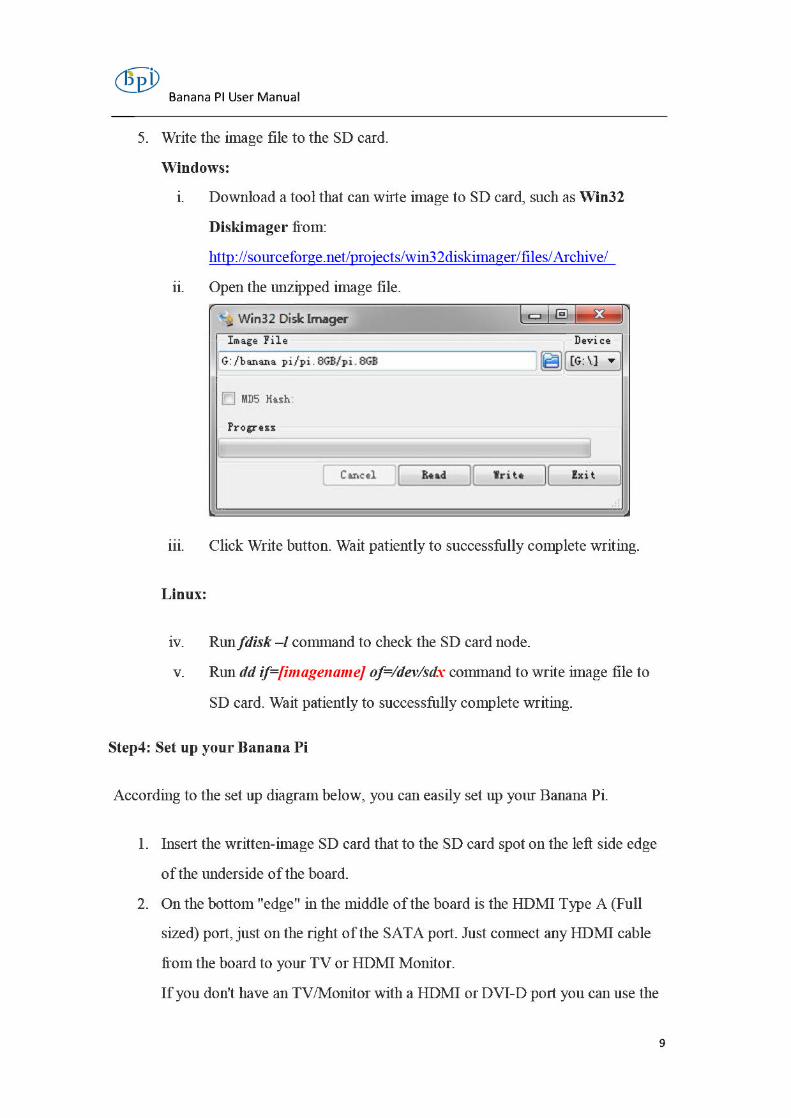
5. Write the image file to the SD card.
Windows:
1. Download a tool that can wirte image to SD card, such as Win32
Diskimager fi:om:
http://sourceforge.net/projects/win32diskimager/files/ Archive/
n. Open the unzipped image file.
' .. 1Nin32 Disk lmager l ·c::rj..§-1-Si.-l
Image File Device
G:/banana pi / pi . 8GB/pi . 8GB ~I IG: \J · ) [!] MDS Hash
Progress
j
l Cancel JI Read 11 l'rite ][ Exit 1
m. Click Write button. Wait patiently to successfully complete writing.
Linux:
1v. Runfdisk -1 command to check the SD card node.
v. Run dd if=[imagename] of=/devlsdx command to write image file to
SD card. Wait patiently to successfully complete writing.
Step4: Set up your Banana Pi
According to the set up diagram below, you can easily set up your Banana Pi.
l . Insert the written-image SD card that to the SD card spot on the left si de edge
ofthe underside ofthe board.
2. On the bottom "edge" in the middle ofthe board is the HDMI Type A (Full
sized) p01t, just on the right ofthe SATA p01t. Just connect any HDMI cable
fi:om the board to your TV or HDMI Monitor.
Ifyou don't have an TV/Monitor with a HDMI or DVI-D port you can use the
9

Banana PI User Manual
yellow AV jack located in the middle ofthe "top" edge and the 3.5 nun stereo
headphone jack to the right of it.
3. Plug a USB keyboard and mouse into the USB slots located on the right edge.
4. Just under the USB ports on the right edge is the ethernet connector for anyone
who wants to plug the Banana Pi into a wired network.
5. Finally, at the very left of the bottom edge is the micro-usb power
connector. Plug in a regulated power supply that is rated at 5V ±5% and at
least 700mA (or 0.7A). Any number bigger than 700 mA (like lOOOmA) will
also work. Avoid using the smaller chargers used for small GSM phones, as
these are often unregulated, even ifthey claim "5V lA", they may do "5V"
and may do "lA", but not at the same time!
The mini-USB (on the left) is the wrong one. It's thicker and looks like a
trapezoid with its sides pinched in. The micro-USB (on the right) is the
conect one. It is thinner and also looks like a trapezoid except it's sides are
rounded outward.
10

Banana PI User Manual
If all goes well, the Banana Pi will boot in a few minutes. The screen will display the
OS GUI.
StepS: Shut down your Banana Pi
Y o u can use the GUI to shut down the Banana Pi safely.
Also you can run the cornmand in the tenninal:
sudo halt
or
sudo shutdown -h.
This will shut down the PI safely, (just use the power key to tmn off might
damage the SD-cards file system). After that you can press the power key for 5
seconds to turn it off.
11

@eP Banana PI User Manual
If all is well ,so you can use banana pi now.
GPIO specificat ion
Banana Pi 26-pin GPIO
Banana Pi has a 26-pin GPIO header that matches that ofthe ModelA and Model B Raspberry Pi. Following is the
Banana Pi GPIO Pinout:
Pin 1
3.3V1
12C-SDA
12C-SCL
GCLK
GND
GPIOO
GPIO 2
GPIO 3
3.3V2
SPI MOSI
SPI M ISO
SPI CLK
GND
o o o o o o o o o o o o o
Pin 25
o o o o o o o o o o o o o
Pi n 2
SVl
SV2
GND
UART-TX
UART-RX
GPIO 1
GND
GPI0 4
GPIO 5
GND
GPIO 6
SP I CEO
SP I CEl
Pin 26
12
® Banana PI User Manua l
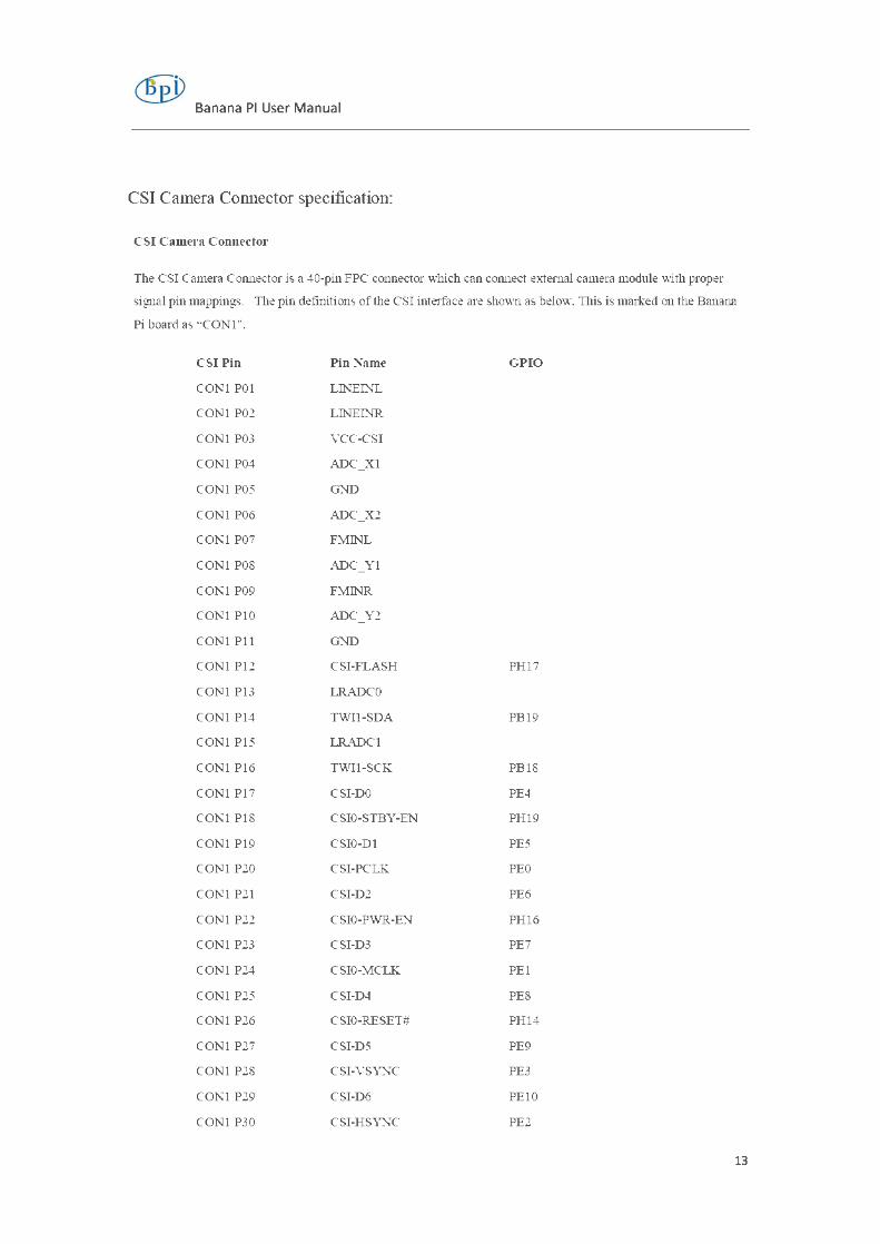
CSI Camera Connector specification:
CSI Camera Connector
The CSI Camera Cmmector is a 40-pin FPC connector which can cmmect externa! camera module with proper
signa! pin mappings. The pin definitions ofthe CSI inteiface are shown as below. Tilis is marked on the Banana
Pi board as "CONl ".
CSI Pin Pin Name GPIO
CONl POI LINEINL
CONl P02 LINEINR
CONl P03 VCC-CSI
CONl P04 ADC Xl
CONl POS GND
CONl P06 ADC X2
CONl P07 FMINL
CONl POS ADC Yl
CONl P09 FMINR
CONl PlO ADC Y2
CONl Pll GND
CONl Pl2 CSI-FLASH PH17
CONl Pl3 LRADCO
CONl Pl4 TWil-SOA PB19
CONl PIS LRADCl
CONl Pl6 TWil-SCK PBlS
CONl Pl7 CSI-00 PE4
CONl PIS CSIO-STBY-EN PH19
CONl Pl9 CSI0-01 PES
CONl P20 CSI-PCLK PEO
CONl P21 CSI-02 PE6
CONl P22 CSIO-PWR-EN PH16
CONl P23 CSI-D3 PE7
CONl P24 CSIO-MCLK PEl
CONl P2S CSI-04 PES
CONl P26 CSIO-RESET# PH14
CONl P27 CSI-OS PE9
CONl P2S CSI-VSYNC PE3
CONl P29 CSI-06 PElO
CONl P30 CSI-HSYNC PE2
13

Banana PI User Manual
CONl P31
CONl P32
CONl P33
CONl P34
CONl P35
CONl P36
CONl P37
CONl P38
CONl P39
CONl P40
LVDS specification
L VDS (LCD display interface)
CS1-07
CSil-STBY-EN
RESET#
CSil-RESET#
CSI-IOO
HPR
HPL
IPSOUT
GND
IPSOUT
PEll
PH18
PH13
PHll
The L VDS Cormector is a 40-pin FPC connector which can cormect external LCO panel (L VDS) and touch screen
(I2C) module as well. The pin definitions ofthis connector are shown as below. This is marked on the Banana Pi
board as "CON2".
Multiplex Function Select GPIO LVDS Pin PinName
Multi 1 Multi 2
CON2 POI IPSOUT(5V output)
CON2P02 TWI3-SOA Pll
CON2 P03 IPSOUT(5V output)
CON2P04 TWI3-SCK PIO
CON2 POS GNO
CON2P06 LC00-100 PH7
CON2 P07 LCDI0-03 PH12
CON2P08 LC00-101 PHS
CON2 P09 LC00-00 LVDSO-VPO POO
CON2 PlO PWMO PB2
CON2 Pll LCOO-Dl LVDSO-VNO POI
CON2 Pl2 LC00-102 PH9
CON2Pl3 LC00-02 LVDSO-VPI P02
CON2 Pl4 LCOO-OE P025
CON2 Pl5 LC00-03 LVDSO-VNI P03
CON2 Pl6 LCOO-VSYNC P027
CON2 Pl7 LC00-04 LVDSO-VP2 P04
CON2 PIS LCOO-HSYNC P026
CON2 Pl9 LC00-05 LVDSO-VN2 POS
CON2P20 LCOO-CS PH6
14

Qfpj) Banana PI User Manual
CON2 P21 LC00-06 LVDSO-VPC P06
CON2P22 LCOO-CLK P024
CON2P23 LCOO-D7 LVDSO-VNC P07
CON2P24 GNO
CON2 P25 LC00-08 LVDSO-VP3 P08
CON2P26 LC00-023 P023
CON2 P27 LC00-09 LVDSO-VN3 P09
CON2P28 LC00-022 P022
CON2P29 LC00-010 P010
CON2 P30 LC00-021 P021
CON2 P31 LC00-011 POli
CON2P32 LC00-020 P020
CON2 P33 LC00-012 P012
CON2 P34 LC00-019 P019
CON2 P35 LC00-013 P013
CON2 P36 LC00-018 P018
CON2 P37 LC00-014 P014
CON2 P38 LC00-017 P017
CON2 P39 LC00-015 P015
CON2P40 LC00-016 P016
UART specification:
Thejumper J11 is the UART inteiface. For developers ofBanana Pi, this is an easywayto get the UART console
output to check the system status and log message.
Jll Pin
Jl1 Pin1
Jl1 Pin2
PinName
TXD
RXD
Multiplex Function Select
Multi 1
UARTO-TX
UARTO-RX
GPIO
Multi 2
PB22
PB23
The jumper J12 provides the power source including 3.3V and 5V. There is a pair ofUART TXIRX signals
output here.
J12 Pin Pin Name
Jl2 Pin 1 5V
J12Pin2 3.3V
J12 Pin3 NC
J12Pin4 RXD
J12 Pin5 NC
Jl2 Pin6 TXD
Multiplex Function Select
Multi 1
I0-7
UART7 RX
I0-8
UART7 TX
GPIO
Multi 2
PH5
PI21
PH3
PI20
15

® Banana PI User Manual
Jl2Pin7 GND
J12Pin8 GND
All GPIO define list:
5V
SDA 5V
se GND
GCLK TXD
GND RXD
lOO Io- 1
10 2 Gl'\0
10 3 l04
105
GND
lQ-6
o CSl
Banana Pi V1.4 PIN define
PIN PIN define GPIO
CONI-POI LINEINL CON1-P02 LINEINR
16

® Banana PI User Manual
CON 1-P04 CON 1-P06 CON 1-P08 ADC Yl CON l-PlO ADC Y2 CON 1-Pl3 LRADCO
CON 1-Pl5 LRADCl
CON 1-Pl7 CSI-DO PE4 CON 1-Pl9 CSI-Dl PES CON 1-P21 CSI-D2 PE6 CON 1-P23 CSI-D3 PE? CON 1-P25 CSI-D4 PE8 CON 1-P27 CSI-D5 PE9 CON 1-P29 CSI-D6 PElO CON 1-P31 CSI-D7 PEll CON 1-P20 CSI-PCLK PEO CON 1-P24 CSI-MCLK PEl CON 1-P28 CSI-VSYNC PE3 CON 1-P30 CSI-HSYNC PE2 CON1-Pl8 CSIO-STBY -EN PH19 CON1-P26 CSIO-RESET# PH14 CON1-P32 CSil-STBY-EN PH18
CON1-P34 CSil-RESET# PH13 CON1-Pl4 TWil-SDA PB19
CON1-Pl6 TWil-SCK PB18 CON1-Pl2 CSI-FLASH PH17 CON1-P22 CSIO-PWR-EN PH16 CON1-P35 CSI-100 PHll
CON2-P09 LCDO-DOO PDO CON2-Pll LCDO-DOl PDl
CON2-Pl3 LCDO-D02 PD2 CON2-Pl5 LCDO-D03 PD3 CON2-Pl7 LCDO-D04 PD4
17

® Banana PI User Manual
CON2-Pl9 LCDO-D05 PD5
CON2-P21 LCDO-D06 PD6 CON2-P23 LCDO-D07 PD7
CON2-P25 LCDO-D08 PD8 CON2-P27 LCDO-D09 PD9
CON2-P29 LCDO-DlO PDlO CON2-P31 LCDO-Dll PDll
CON2-P33 LCDO-Dl2 PD12 CON2-P35 LCDO-Dl3 PD13
CON2-P37 LCDO-Dl4 PD14 CON2-P39 LCDO-Dl5 PD15
CON2-P40 LCDO-Dl6 PD16 CON2-P38 LCDO-Dl7 PD17
CON2-P36 LCDO-Dl8 PD18
CON2-P34 LCDO-Dl9 PD19 CON2-P32 LCDO-D20 PD20
CON2-P30 LCDO-D21 PD21 CON2-P28 LCDO-D22 PD22
CON2-P26 LCDO-D23 PD23 CON2-P22 LCDO-CLK PD24
CON2-P20 LCDO-CS PH6 CON2-Pl8 LCDO-HSYNC PD26
CON2-Pl6 LCDO-VSYNC PD27 CON2-Pl4 LCDO-DE PD25
CON2-Pl2 LCD0-102 PH9
CON2-Pl0 PWMO PB2 CON2-P08 LCD0-10 1 PH8
CON2-P06 LCD0-100 PH7 CON2-P04 TWI3-SCK PIO
CON2-P02 TWI3-SDA Pll CON2-P07 LCDI0 -03 PH12
CON3-Pl8 CAN RX PH21 CON3-Pl6 CAN __ TX PH20
CON3-P23 SPIO_CLK Plll CON3-P21 SPIO MISO PI13
18
@eP Banana PI User Manual
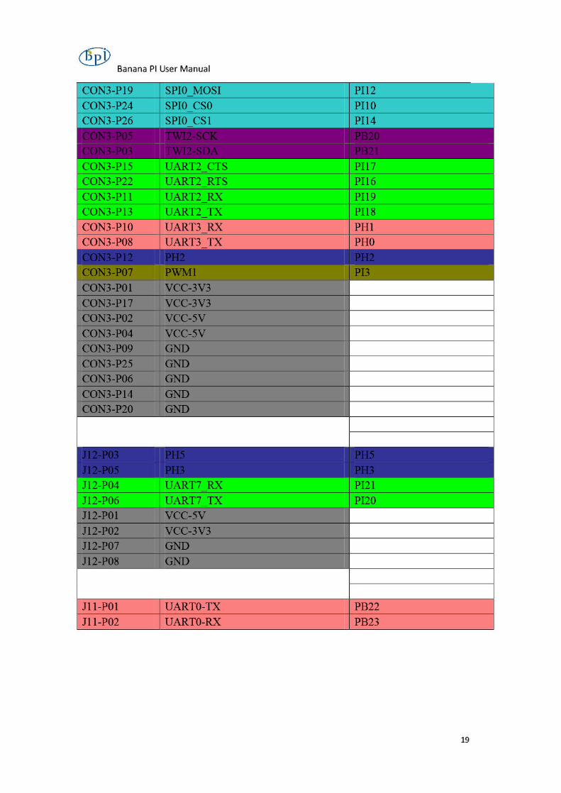
CON3-Pl9 PI12 CON3-P24 PilO
CON3-P22 UART2 RTS PI16
CON3-Pll UART2 RX PI19 CON3-Pl3 u PI18 CON3-PIO u PHI CON3-P08 UART3 TX PHO
Jll-POI UARTO-TX PB22 Jll-P02 UARTO-RX PB23
19