Embed Size (px)
Citation preview
7th International LS-DYNA Users Conference Penetration/Explosive
6-15
BALLISTIC IMPACT MODELING OF COMPOSITE MATERIALS
Chian-Fong Yen Materials Sciences Corporation
500 Office Center Drive Fort Washington, PA 19034
(215) 542-8400 yen@materials_sciences.com
Keywords: Ballistic Impact, Composite Materials, Damage Mechanics, Material Model, Rate Effect
ABSTRACT
A computational constitutive model has been developed to characterize the progressive failure be-haviors of composite laminates under high velocity ballistic impact conditions. The composite failure model has been implemented within LS-DYNA as a regular material subroutine. The inte-grated code was successfully utilized to predict the damage and ballistic behavior of composite laminates subjected to various ballistic impact conditions. The availability of this design tool will greatly facilitate the development of composite structures with enhanced ballistic survivability.

Penetration/Explosive 7th International LS-DYNA Users Conference
6-16
INTRODUCTION Failure modeling of composite materials under impact loading has been the subject of numerous studies, e.g., Abrate (1994), Richarson and Wisheart (1996), Choi and Chang (1990) and Davies and Zhang (1995). However, few studies have been reported on modeling progressive failure in composites under high strain rate ballistic loading. In this work, a rate dependent progressive failure model has been developed to account for the nonlinear and rate dependent behavior commonly observed for fiber reinforced composite materials under high strain rate conditions. The composite failure model adopted within LS-DYNA is the Chang-Change (1987) model (MAT 22), which pro-vides various fiber and matrix failure modes solely due to in-plane stresses in unidirectional lamina. In this 2D fail-ure model, the failure mode due to out-of-plane shear and normal stresses are neglected. While this may be suffi-cient for composite structures under in-plane loading, this model may be unable to capture transverse impact failures for which all six stress components are known to contribute to damage development. To enhance the modeling capability of the progressive failure behavior of composite laminates due to transverse im-pact, a composite lamina model based on the 3D stress field has been developed by Materials Sciences Corporation (MSC). It has been implemented into LS-DYNA as MAT 161. This failure model can be used to effectively simulate fiber failure, matrix damage, and delamination behavior under all conditions - opening, closure, and sliding of failure surfaces. Furthermore, this progressive failure modeling approach is advantageous as it enables one to predict de-lamination when locations of delamination sites cannot be anticipated; i.e., locations of potential delamination initia-tion is calculated without a-priori definition of an interlaminar crack surface. This failure model has been success-fully utilized to characterize the impact damage in composite structures for a wide range of impact problems (Yen, et al., 1998a, 1998b, 1999). In this work, the MSC lamina failure model for fabric composites has been extended to model the progressive post-failure behavior by adopting the continuum damage mechanics approach, which characterizes the growth of damage by decreasing the material stiffness. A continuum damage mechanics (CDM) model for unidirectional composite layers based on plane-stress state was reported by Matzenmiller, et al., (1995). Recent studies reported by William and Vaziri (1995) and VAN HOOF, et al., (1998) have shown that post-failure models of CDM can significantly im-prove the prediction of impact damage of composite structures. Note that non-interactive failure criteria (based on maximum strain assumption) due to tension, punch shear and crush loading are provided by VAN HOOF, et al., (1998) to account for the major failure modes of ballistic impact of composite materials. This model, however, ne-glects the rate dependent effect. High strain rate and high pressure loading conditions generally occur in the impact area when a composite material is subjected to high velocity ballistic impact. Experimental characterization of the mechanical behavior of composite materials under high strain rate conditions has been reported in literature (e.g., Harding and Ruiz 1998 and Al-Hassani and Kaddour 1998). It has been shown that some armor materials such as woven glass and aramid compos-ites exhibit significant rate sensitivity (Harding 1979 and Welsh and Harding 1985). In order to account for the ex-perimentally observed nonlinear and rate dependent behavior, a general rate dependent progressive failure model for a fabric lamina has been developed using the CDM approach provided by Matzenmiller, et al., (1995). The failure criteria and the associated property degradation models are described as follows.
COMPOSITE PROGRESSIVE FAILURE MODEL Failure models based on the 3D strains in a composite layer with improved progressive failure modeling capability are established for a plain weave fabric layer. It can be used to effectively simulate the fiber failure and delamination behavior under high strain-rate and high pressure ballistic impact conditions. This 3D composite failure model has been successfully integrated into LS-DYNA.
The fabric failure criteria are expressed in terms of ply level engineering strains ( )x y z xy yz zx, , , , ,ε ε ε ε ε ε with x, y
and z denoting the in-plane fill, in-plane warp and out-of-plane directions, respectively. The associated elastic
moduli are ( )x y z xy yz zxE ,E ,E ,G ,G ,G .
Lamina Damage Functions
7th International LS-DYNA Users Conference Penetration/Explosive
6-17
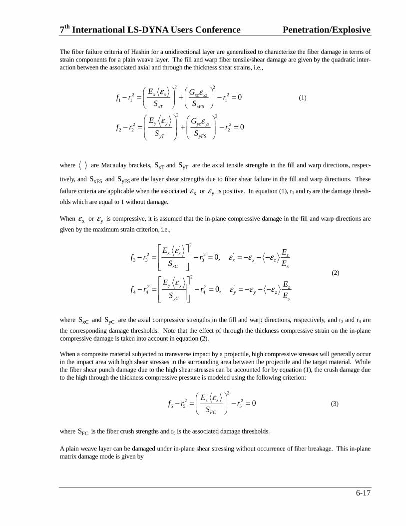
The fiber failure criteria of Hashin for a unidirectional layer are generalized to characterize the fiber damage in terms of strain components for a plain weave layer. The fill and warp fiber tensile/shear damage are given by the quadratic inter-action between the associated axial and through the thickness shear strains, i.e.,
2 2
2 21 1 1
2 2
2 22 2 2
0
0
x x xz xz
xT xFS
y y yz yz
yT yFS
E Gf r r
S S
E Gf r r
S S
ε ε
ε ε
− = + − =
− = + − =
(1)
where are Macaulay brackets, xTS and yTS are the axial tensile strengths in the fill and warp directions, respec-
tively, and xFSS and yFSS are the layer shear strengths due to fiber shear failure in the fill and warp directions. These
failure criteria are applicable when the associated xε or yε is positive. In equation (1), r1 and r2 are the damage thresh-
olds which are equal to 1 without damage. When xε or yε is compressive, it is assumed that the in-plane compressive damage in the fill and warp directions are
given by the maximum strain criterion, i.e.,
2'
2 2 '3 3 3
2'
2 2 '4 4 4
0,
0,
εε ε ε
εε ε ε
− = − = = − − −
− = − = = − − −
x x zx x z
xC x
y y zy y z
yC y
E Ef r r
S E
E Ef r r
S E
(2)
where xCS and yCS are the axial compressive strengths in the fill and warp directions, respectively, and r3 and r4 are
the corresponding damage thresholds. Note that the effect of through the thickness compressive strain on the in-plane compressive damage is taken into account in equation (2). When a composite material subjected to transverse impact by a projectile, high compressive stresses will generally occur in the impact area with high shear stresses in the surrounding area between the projectile and the target material. While the fiber shear punch damage due to the high shear stresses can be accounted for by equation (1), the crush damage due to the high through the thickness compressive pressure is modeled using the following criterion:
2
2 25 5 5 0
ε − = − =
z z
FC
Ef r r
S (3)
where FCS is the fiber crush strengths and r5 is the associated damage thresholds.
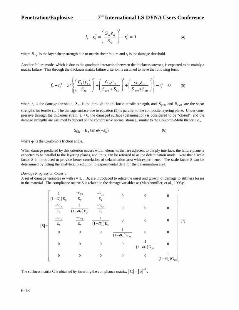
A plain weave layer can be damaged under in-plane shear stressing without occurrence of fiber breakage. This in-plane matrix damage mode is given by
Penetration/Explosive 7th International LS-DYNA Users Conference
6-18
2
2 26 6 6 0
ε − = − =
xy xy
xy
Gf r r
S (4)
where xyS is the layer shear strength due to matrix shear failure and r6 is the damage threshold.
Another failure mode, which is due to the quadratic interaction between the thickness stresses, is expected to be mainly a matrix failure. This through the thickness matrix failure criterion is assumed to have the following form:
22 2
2 2 27 7 7
0 0
0εε ε − = + + − = + +
yz yzz z zx zx
zT yz SR zx SR
GE Gf r S r
S S S S S (5)
where r7 is the damage threshold, zTS is the through the thickness tensile strength, and yz0S and zx0S are the shear
strengths for tensile εz. The damage surface due to equation (5) is parallel to the composite layering plane. Under com-pressive through the thickness strain, εz < 0, the damaged surface (delamination) is considered to be “closed”, and the damage strengths are assumed to depend on the compressive normal strain εz similar to the Coulomb-Mohr theory, i.e.,
SR z zS E tanϕ ε= − (6)
where ϕ is the Coulomb’s friction angle. When damage predicted by this criterion occurs within elements that are adjacent to the ply interface, the failure plane is expected to be parallel to the layering planes, and, thus, can be referred to as the delamination mode. Note that a scale factor S is introduced to provide better correlation of delamination area with experiments. The scale factor S can be determined by fitting the analytical prediction to experimental data for the delamination area. Damage Progression Criteria A set of damage variables ωi with i = 1, …6, are introduced to relate the onset and growth of damage to stiffness losses in the material. The compliance matrix S is related to the damage variables as (Matzenmiller, et al., 1995):
[ ]
( )
( )
( )
( )
( )
( )
yx zx
1 x y z
xy zy
x 2 y z
yzxz
x y 3 z
4 xy
5 yz
6 zx
10 0 0
1 E E E
10 0 0
E 1 E E
10 0 0
E E 1 ES
10 0 0 0 0
1 G
10 0 0 0 0
1 G
10 0 0 0 0
1 G
ν νϖν ν
ϖνν
ϖ
ϖ
ϖ
ϖ
− − − − − −
−− − =
−
− −
(7)
The stiffness matrix C is obtained by inverting the compliance matrix, [ ] [ ] 1C S
−= .
7th International LS-DYNA Users Conference Penetration/Explosive
6-19
As suggested in Matzenmiller, et al., (1995), the growth rate of damage variables, ϖ& i , is governed by the damage rule
of the form
ϖ φ=∑& i j ijj
q (8)
where the scalar functions φi (i=1,…6) control the amount of growth and the vector-valued functions qij (i=1,…6, j=1,…7) provide the coupling between the individual damage variables (i) in the various damage modes (j). The dam-age criteria fi – ri
2 = 0 of equations (1 – 5) provide the damage surfaces in strain space. Damage growth, φi > 0, will oc-cur when the strain path crosses the updated damage surface fi – ri
2 = 0 and the strain increment has a non-zero compo-
nent in the direction of the normal to the damage surface, i.e., 0εε
∂ >∂∑ &i
jj j
f. Combined with a damage growth func-
tion ( )i j j, , j 1,...6γ ε ϖ = , φi is assumed to have the form
( )φ γ εε
∂=∂∑ &i
i i jj j
fno sumationover i (9)
Choosing
( ) 121
12
γ ϖ−
= −m
i i if (10)
and noting that
εε
∂ =∂∑ &&i
j ij j
ff (11)
for the quadratic functions of equations (A1) to (A5), lead to
( ) 121
1 ( )2
φ ϖ−
= − &m
i i i if f no summation over i (12)
where 'iϖ is the damage variable associated with the ith failure mode, and m is a material constant.
For the fiber tensile/shear and compressive damage of modes 1 to 4, the damage coupling vector q1i , q2i, q3i and q4i are chosen such that the fiber damage in either the fill and warp direction results in stiffness reduction in the loading direc-tion and in the related shear directions. For the fiber crush damage of mode 5, the damage coupling vector q5i is chosen such that all the stiffness values are reduced as an element is failed under the crush mode. For the in-plane matrix shear failure of mode 6, the stiffness reduction due to q6i is limited to in-plane shear modulus, while the through the thickness matrix damage (delamination) of mode 7, the coupling vector q7i is chosen for the through thickness tensile modulus and shear moduli. The damage coupling functions qij are then
[ ]
1 0 1 0 1 0 0
0 1 0 1 1 0 0
0 0 0 0 1 0 0q
1 1 1 1 1 1 0
0 0 1 1 1 0 1
1 1 0 0 1 0 1
=
(13)
Utilizing the damage coupling functions of equation (13) and the growth function of equation (12), a damage variable ϖi can be obtained from equation (8) for an individual failure mode j as
Penetration/Explosive 7th International LS-DYNA Users Conference
6-20
( )11
1 , 1ϖ−
= − ≥mjr
mi je r (14)
Note that the damage thresholds ri given in the damage criteria of equations (1 – 5) are continuously increasing functions with increasing damage. The damage thresholds have an initial value of one, which results in a zero value for the asso-ciated damage variable ϖi from equation (14). This provides an initial elastic region bounded by the damage functions in strain space. The nonlinear response is modeled by loading on the damage surfaces to cause damage growth with increasing damage thresholds and the values of damage variables ϖi. After damage initiated, the progressive damage model assumes linear elastic response within the part of strain space bounded by the updated damage thresholds. The elastic response is governed by the reduced stiffness matrix associated with the updated damage variables ϖi given in equation (7). When fiber tensile/shear damage is predicted in a layer by equation (1), the load carrying capacity of that layer in the associated direction is reduced to zero according to damage variable equation (14). For compressive fiber damage due to equation (2), the layer is assumed to carry a residual axial load in the damaged direction. The damage vari-
ables of equation (14) for the compressive modes have been modified to account for the residual strengths of xCRS
and yCRS in the fill and warp directions, respectively, as reported in Yen and Caiazzo (2001).
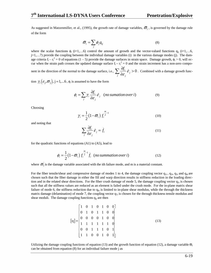
Figure 1 shows typical axial tensile and compressive stress-strain curves obtained from the damage model. Under monotonic loading, Figure 1a shows that the model provides an initial elastic region up to the strength values (85 ksi for tension and 50 ksi for compression) and a softening region after damage initiated (using a damage parameter m=4). Note that the compressive stress reduces to a residual strength of 15 ksi and remains constant for continuous compressive loading. Figure 1b shows stress-strain curves due to cyclic loading along the axial direction x. It dem-onstrates the effect of damage history on the stress-strain response. Note that the unloading and reloading stress-strain curves within the damage surface follow the reduced elastic modulus, which is given by the updated damage parameter for the axial fiber damage mode.
-60000
-40000
-20000
0
20000
40000
60000
80000
100000
-0.04 -0.02 0 0.02 0.04 0.06
Strain, in/in
Str
ess,
psi
Sxx, Tension (m=4)
Sxx. Comp. (m=4)
-60000
-40000
-20000
0
20000
40000
60000
80000
100000
-0.04 -0.02 0 0.02 0.04 0.06
Strain, in/in
Str
ess,
psi
Cyclic (1)
Cyclic (2)
(a) (b)
Figure 1. Axial Stress-Strain Curves for Damage Model Under
(a) Monotonic and (b) Cyclic Loading Conditions For through the thickness matrix (delamination) failure given by equation (5), the in-plane load carrying capacity within the element is assumed to be elastic (i.e., no in-plane damage). The load carrying behavior in the through the thickness direction is assumed to depend on the opening or closing of the matrix damage surface. For tensile mode, εz >0, the through the thickness stress components are softened and reduced to zero due to the damage criteria described above. For compressive mode, εz <0, the damage surface is considered to be closed, and thus, σz is assumed to be elas-tic, while τyz and τzx are allowed to reduce to a sliding friction stress of equation (6). Accordingly, for the through the
7th International LS-DYNA Users Conference Penetration/Explosive
6-21
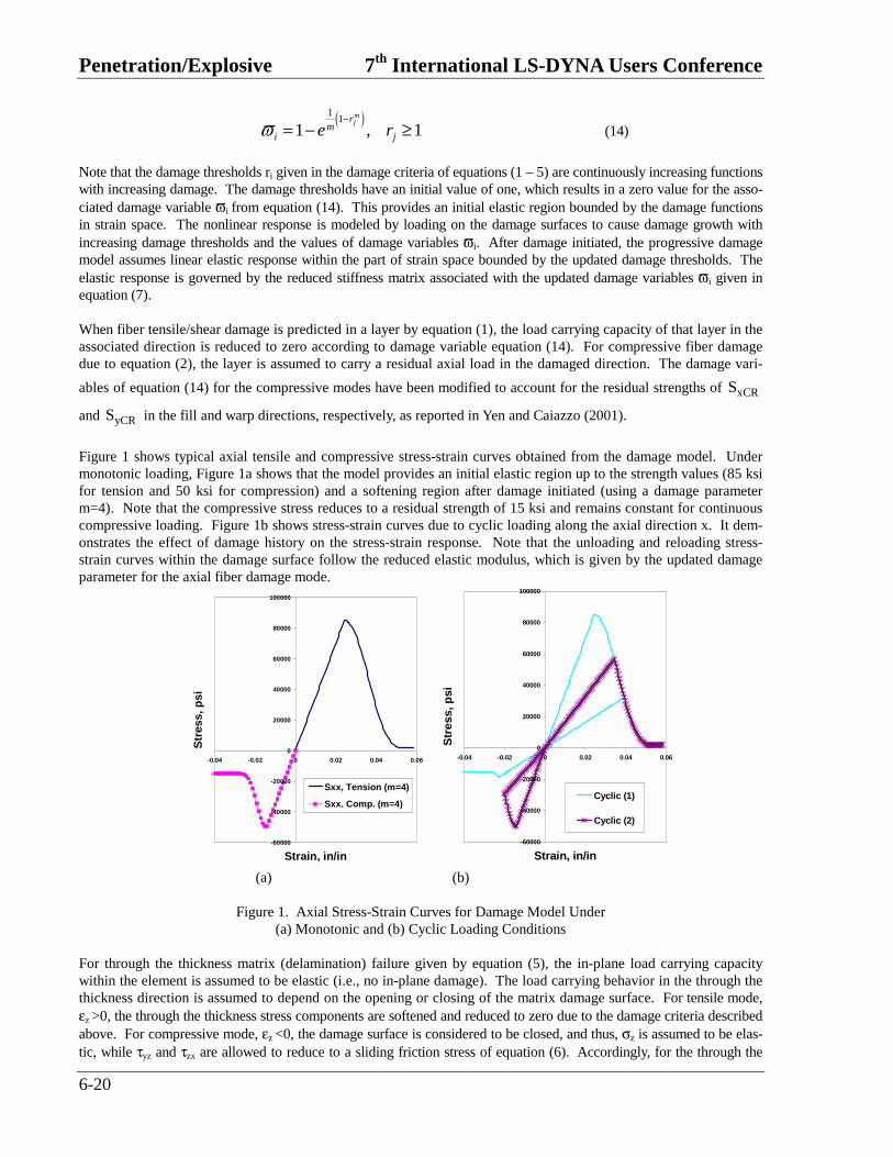
thickness matrix failure of mode 7 under compressive mode, the damage variable equation is further modified to account for the residual sliding strength SSR in Yen and Caiazzo (2001).. Figure 2 shows typical axial shear stress-strain curves obtained from the damage model. Shown in Figure 2a are the shear stress-strain curves for τzx with tensile through the thickness normal loads (opening delamination). Figure 2b shows the effect of the compressive through the thickness normal stress (closing delamination), σz on the τzx stress-strain response for a Coulomb’s friction angle ϕ =200.
-20000
-15000
-10000
-5000
0
5000
10000
15000
-0.05 -0.04 -0.03 -0.02 -0.01 0 0.01 0.02 0.03 0.04 0.05
Shear Strain, in/in
Sh
ear
Str
ess,
psi
szx, open delm,monotonicszx, open delm,cyclic
-20000
-15000
-10000
-5000
0
5000
10000
15000
-0.05 -0.04 -0.03 -0.02 -0.01 0 0.01 0.02 0.03 0.04 0.05
Shear Strain, in/in
Sh
ear
Str
ess,
psi
szx, close delm,monotonic
szx, close delm,cyclic
(a) (b)
Figure 2. Shear Stress-Strain Curves for Damage Model under the Effect of Through the
Thickness Normal Load, (a) Opening Delamination and (b) Closing Delamination The effect of strain rate on the layer strength values of the fiber failure modes is modeled by multiplying the associ-ated strength values {SRT} by a scale factor as
{ } { } { }
{ } { }
00
1 lnRT rate
xxT
yyT
xxC
RT yC y
FC z
xFSzx
yFSyz
S S C
S
S
S
S S and
S
S
S
εε
ε
ε
ε
ε ε
εε
ε
= +
= =
&
&
&
&
&
& &
&
&
&
(15)
where Crate is the strain rate constant, and { }0S are the available strength values of { }RTS at the reference strain
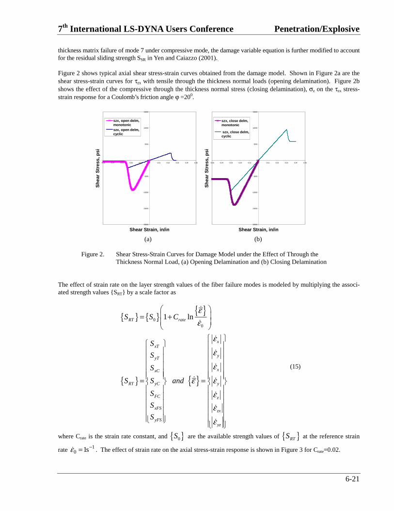
rate 10 1sε −=& . The effect of strain rate on the axial stress-strain response is shown in Figure 3 for Crate=0.02.
Penetration/Explosive 7th International LS-DYNA Users Conference
6-22
0
20000
40000
60000
80000
100000
120000
0 0.01 0.02 0.03 0.04 0.05 0.06 0.07 0.08
Strain, in/in
Str
ess,
psi
erate=1erate=10erate=100erate=1000erate=10000erate=100000
Figure 3. Axial Tensile Stress-Strain Curves for Damage Model Under Various Constant Strain Rate Loading
The functionality of eroding elements is available within the material subroutine by passing in and out some erosion variables. The erosion criterion is formulated by using the fiber tensile failure criterion, equation (1). When fiber tensile failure in both axial directions is predicted in an element, the erosion variables are properly set and passed to LS-DYNA for eliminating the element. The element erosion is necessary in order to avoid the excess distortion of a failed element.
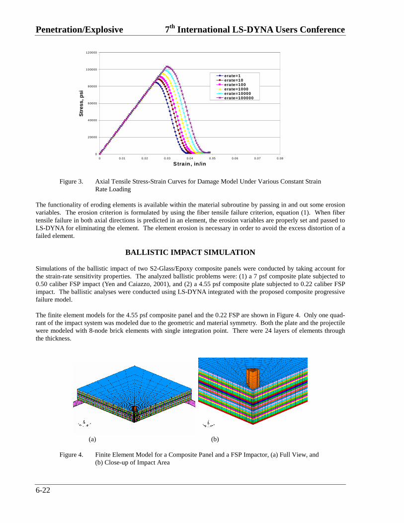
BALLISTIC IMPACT SIMULATION Simulations of the ballistic impact of two S2-Glass/Epoxy composite panels were conducted by taking account for the strain-rate sensitivity properties. The analyzed ballistic problems were: (1) a 7 psf composite plate subjected to 0.50 caliber FSP impact (Yen and Caiazzo, 2001), and (2) a 4.55 psf composite plate subjected to 0.22 caliber FSP impact. The ballistic analyses were conducted using LS-DYNA integrated with the proposed composite progressive failure model. The finite element models for the 4.55 psf composite panel and the 0.22 FSP are shown in Figure 4. Only one quad-rant of the impact system was modeled due to the geometric and material symmetry. Both the plate and the projectile were modeled with 8-node brick elements with single integration point. There were 24 layers of elements through the thickness.
(a) (b)
Figure 4. Finite Element Model for a Composite Panel and a FSP Impactor, (a) Full View, and
(b) Close-up of Impact Area
7th International LS-DYNA Users Conference Penetration/Explosive
6-23
The panel was placed over a rigid ring with a rigid body contact surface assumed between the plate and the ring. Initial velocity was provided to the impactor to start the analysis, the projectile metals were assumed to behave as elastoplastic materials. An eroding contact algorithm provided within LS-DYNA together with the integrated failure model were used to simulate the contact and penetration between the projectile and the impact area of the plate. The element erosion criterion was given by the fiber failure. All failed elements were deleted and the contact surfaces were automatically updated to the next layer of material.
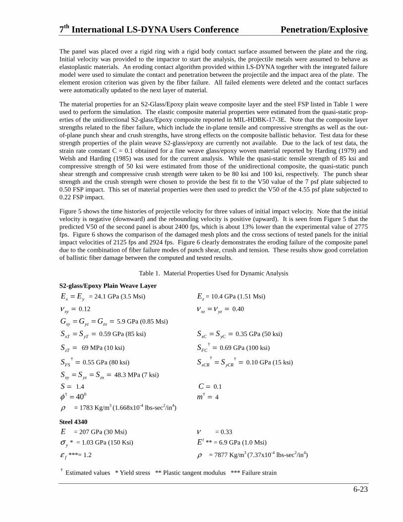
The material properties for an S2-Glass/Epoxy plain weave composite layer and the steel FSP listed in Table 1 were used to perform the simulation. The elastic composite material properties were estimated from the quasi-static prop-erties of the unidirectional S2-glass/Epoxy composite reported in MIL-HDBK-17-3E. Note that the composite layer strengths related to the fiber failure, which include the in-plane tensile and compressive strengths as well as the out-of-plane punch shear and crush strengths, have strong effects on the composite ballistic behavior. Test data for these strength properties of the plain weave S2-glass/epoxy are currently not available. Due to the lack of test data, the strain rate constant C = 0.1 obtained for a fine weave glass/epoxy woven material reported by Harding (1979) and Welsh and Harding (1985) was used for the current analysis. While the quasi-static tensile strength of 85 ksi and compressive strength of 50 ksi were estimated from those of the unidirectional composite, the quasi-static punch shear strength and compressive crush strength were taken to be 80 ksi and 100 ksi, respectively. The punch shear strength and the crush strength were chosen to provide the best fit to the V50 value of the 7 psf plate subjected to 0.50 FSP impact. This set of material properties were then used to predict the V50 of the 4.55 psf plate subjected to 0.22 FSP impact.
Figure 5 shows the time histories of projectile velocity for three values of initial impact velocity. Note that the initial velocity is negative (downward) and the rebounding velocity is positive (upward). It is seen from Figure 5 that the predicted V50 of the second panel is about 2400 fps, which is about 13% lower than the experimental value of 2775 fps. Figure 6 shows the comparison of the damaged mesh plots and the cross sections of tested panels for the initial impact velocities of 2125 fps and 2924 fps. Figure 6 clearly demonstrates the eroding failure of the composite panel due to the combination of fiber failure modes of punch shear, crush and tension. These results show good correlation of ballistic fiber damage between the computed and tested results.
Table 1. Material Properties Used for Dynamic Analysis
S2-glass/Epoxy Plain Weave Layer
=x yE E = 24.1 GPa (3.5 Msi) zE = 10.4 GPa (1.51 Msi)
ν =xy 0.12 ν ν= =xz yz 0.40
= = =xy yz zxG G G 5.9 GPa (0.85 Msi)
= =xT yTS S 0.59 GPa (85 ksi) = =xC yCS S 0.35 GPa (50 ksi)
=zTS 69 MPa (10 ksi) † =FCS 0.69 GPa (100 ksi)
† =FSS 0.55 GPa (80 ksi) † †= =xCR yCRS S 0.10 GPa (15 ksi)
= = =xy yz zxS S S 48.3 MPa (7 ksi)
=S 1.4 =C 0.1 † 040φ = † =m 4
ρ = 1783 Kg/m3 (1.668x10⁻⁴ lbs-sec2/in4)
Steel 4340
E = 207 GPa (30 Msi) ν = 0.33
σ y * = 1.03 GPa (150 Ksi) tE ** = 6.9 GPa (1.0 Msi)
ε f ***= 1.2 ρ = 7877 Kg/m3 (7.37x10⁻⁴ lbs-sec2/in4)
† Estimated values * Yield stress ** Plastic tangent modulus *** Failure strain

Penetration/Explosive 7th International LS-DYNA Users Conference
6-24
-3000
-2500
-2000
-1500
-1000
-500
0
500
0 0.01 0.02 0.03 0.04 0.05 0.06 0.07 0.08 0.09 0.1
Time, msec
Pro
ject
ile V
elo
city
, fp
s
V0=2500 fpsV0=2420 fpsV0=2330 fps
Figure 5. Computed Time Histories of Projectile Velocity for an S2-Glass/Epoxy Composite
Subjected to 0.22 Caliber FSP Impact
(a)
(b)
Figure 6. Comparison of the Finite Element and Experimental Results of Damage 0.55 psf
Composite Panel Subjected to 0.22 Cal. FSP Impact at (a) 2125 fps and (b) 2924 fps
7th International LS-DYNA Users Conference Penetration/Explosive
6-25
CONCLUSIONS A strain rate dependent lamina model based on CDM has been successfully developed and implemented within LS-DYNA for modeling the progressive failure behavior of plain weave composite layers. It can be used to effectively simulate the fiber failure and delamination behavior under high strain-rate and high-pressure ballistic impact condi-tions. The integrated code was successfully utilized to predict the ballistic limit velocity of composite laminates sub-jected to high velocity ballistic impact conditions. Simulations of ballistic impact of composite panels have been conducted by taking account for the strain-rate sensitivity properties. The strain rate effect will need further investi-gation by experimentally characterizing the rate dependent behavior of various composite materials. Correlation for impact damage such as delamination area will also need to be conducted when the test data is available in the future.
ACKNOWLEDGMENT This work was supported by the U.S. Army Research Laboratory under Contract No. DAAD17-00-C-0059.

Penetration/Explosive 7th International LS-DYNA Users Conference
6-26
REFERENCES Abrate, A. (1994). “Impact on Laminated Composites: Recent Advances,” Appl. Mech. Rev., V47, pp. 517-543. Al-Hassani, S.T.S. and Kaddour, A.S. (1998). “Strain Rate Effects on GRP, KRP and CFRP Composite Laminates,” Key Engineering Materials, Vol. 141-143, Trans Tech Publications, Switzerland, pp. 427-452. Choi, H.Y., and Chang, F.K. (1990). “Impact Damage Threshold of Laminated Composites”, in Failure Criteria and Analysis in Dynamic Response, AMD Vol. 107, ASME Applied Mechanics Division, Dallas, TX, November 1990, pp. 31-35. Chang, F.K., and Chang, K.Y. (1987). “A Progressive Damage Model for Laminated Composites Containing Stress Concentration,” J. of Composite Materials, Vol. 21, pp. 834-855. Davies, G.A.O., and Zhang, X. (1995). “Impact Damage Prediction in Carbon Composite Structures”, Int. J. Impact Engng., Vol. 16, pp. 149-170. Harding J. (1979). “The High-Speed Punching of Woven-Roving Glass-Reinforced Composites.” Inst. Phys. Conf. Ser. No. 47: Chapter 3, The Institute of Physics, Bristol and New York, pp. 318-330. Harding, J. and Ruiz, C. (1998). ”The Mechanical Behaviour of Composite Materials under Impact Loading,” Key Engineering Materials, Vol. 141-143, Trans Tech Publications, Switzerland, pp. 403-426. Matzenmiller, A., Lubliner, J., and Taylor, R.L. (1995). “A Constitutive Model for Anisotropic Damage in Fiber-Composites,” Mechanics of Materials, 20, pp. 125-152. Richarson, M.O.W., and Wisheart, M.J. (1996). “Review of Low-Velocity Impact Properties of Composite Materials”, Composites, Vol., 27A, pp. 1123-1131. VAN HOOF, J., WOESWICK, M.J., STRAZNICKY, P.V., BOLDUC, m. AND TYLKO, S.(1998). Proceedings of the 5th International LS-DYNA Users Conference. Welsh, L.M. and Harding, J. (1985) “Effect of Strain Rate on the Tensile Failure of Woven Reinforced Polyester Resin Composite.” Proc. DYMAT 85, Int. Conf. On Mech. And Physical Behaviour of Materials under Dynamic Loading, Jour de Physique, Colloque C5, pp. 405-414. William, K. and Vaziri, R., (1995). “Finite Element Analysis of the Impact Response of CFRP Composite Plates.” Proceedings of the ICCM-11, pp. 532-654. Yen, C.F., Cassin, T., Patterson, J., and Triplett, M. (1998a). “Progressive Failure Analysis of Thin Walled Compos-ite Tubes under Low Energy Impact,” 39th AIAA Structures, Structural Dynamics, and Materials Conference. Yen, C.F., Cassin, T., Patterson, J., and Triplett, M. (1998b). “Progressive Failure Analysis of Composite Sandwich Panels under Blast Loading,” Structures Under Extreme Loading Conditions, ASME PVP-Vol. 361, New York, pp. 203-216. Yen, C.F., Cassin, T., Patterson, J., and Triplett, M. (1999). “Analytical Methods for Assessing Impact Damage in Filament Wound Pressure Vessels,” 44th International SAMPE Symposium and Exposition, Long Beach, CA. May 23-27. Yen, C.F. and Caiazzo, A. (2001). “Innovative Processing of Multifunctional Composite Armor for Ground Vehi-cles.” ARL-CR-484, U.S. Army Research Laboratory, Aberdeen Proving Ground, MD.