Embed Size (px)
Citation preview

Ball Valves Installation,Operation & Maintenance Manual
www.vahn-tech.com
#2906-15 Fort York BoulevardToronto, Ontario, M5V 3Y4, Canada
Tel/Fax: +1 416 342 0001

CONTENTS 1. SCOPE 1
1 1
2
2. INTRODUCTION 3. TECHNI CAL ASSISTANCE
4. DELIVERY
5. VALVE HANDLI NG & STORAGE5.1. Handling 5.2. Storage
22 4
6. VALVE I NSTALLATION 6.1. General 6.2. Flanged ends 6.3. Welded ends
44 6 6 7
7. VALVE OPERATION 7.1. General 7.2. Act7.3. Sealing 7.4. Cavity relief 7.5. Sealant Charging
77 8 8 9 9 9 9 9
7.5.1. 7.5.2.
Stem Seat
7.6. Fire Safety
8. PERIODI C MAINTENANCE 99
8.2. Double block and bleed and 8.3. O rability & torque 8.4. Stem leakage
1010 10 108.5. Sealant charging
9. TROUBL ESHOOTING 10. VALVE DETAILS
1112
11. MAINTENANCE PROCEDURES11.1. Gear st er adjust ocedure
1313 13 14 14 15 16
lacem ocedure11.3. Secondary sealant inj rocedure - Stem11.4. Secondary sealant inj rocedure - Seat ring 11.5. Dismant ocedure11.6. Assembly rocedure
12. SPARES & SEALANTS s
12.2. Sealants 1919 20
APPENDICES
APPENDIX A -TECHNICAL INFORMATION 2121 21
A1. A2.
References Tightening Sequence & Torque.
APPENDIX B - SPECIAL CONSIDERATIONS IN VALVES WITH EXTENDED STEM 24
www.vahn-tech.com

1. SCOPE
1.1. The aim of this manual is to familiarize the users with standard VAHN-TECH Trunnion Mounted Ball Valves and to aid in correct handling, installa n , opera , maintenance and troublesho of the valves.
VAHN-TECH INTERNATIONAL RECOMMENDS TO Read the manual carefully before opening the shipment and installation of the valve.
Refer respec eneral assembly drawings for ascertaining the design, as valves may vary in features and design as required by the customer.
Study check lists, ca ns and illu ons carefully.
2. INTRODUCTION
2.1. Trunnion Mounted Ball valves come with side entry type, two-piece, bolted it Ring type joint) and bu weld ends.
In addi , VAHN-TECH supplies Trunnion Mounted Ball Valves with three piece bolted
body welded body type construc s also.
2.2. Double Block and Bleed
This is a standard feature in Trunnion Mounted Ball Valves MBV), which enables c of the valve seats in the open and closed po n
Cavity Pressure Relief VAHN-TECH TMBV has seats designed to relieve any excessive pressure that builds up in the valve body cavity autom
An t Stem VAHN-TECH TMBV are designed ow out stem arrangement in which the stem is inserted from inside the body.
Sealant Inj n is provided for seat and stem regions for emergency s leak
arrest on valves of sizes 8” and above for full bore valves and 10” and above in case of reduced bore valves.
eatures also provides TMBV with double piston design, which allows the down-
stream seat to seal with pres the upstream side of the valve. It aids in b sealing even during leakage through upstream seat.
VAHN-TECH TMBV can also be provided with exten drives for buried service
3. TECHNICAL ASSISTANCE
3.1. Should you have any queries, feel free to contact sales repres ves.
Salient features of VAHN-TECH Trunnion Mounted Ball Valve:
valves.
www.vahn-tech.com

3.2. While contac ep esenta ves ish the followi d istance:
Valve size and Class sial n e
4. DELIVERY
4.1. a e shipped with t ls y open posiat faces ( excep lves le act
applic ich case, valves shipped closed c .
4.2.
4.3.
Please che to the packin i
lve ide t on the n e an dy of the valve as
4.4.
4.5.
lves a pplied t cove t ts to avo s e to
nce o les efo e install n.
Hand wheels a e lves a ly nd packed sep ly
in its sl sin hesive tape.
CHECK
ls of valves at delValves any d es d n . Con oExtension lines and col n, if any.
In case of a ancies o oned details o case of any kind ofe to the valve on de ase contac assistance.
5.1. Handlin
5.1.1. Valve shall p ly s ed and se o e vi vent possi o
valv ope a nnel.
5.1.2. D lve o o nspo ini of one foot o hend is to e ovin lve.
cas
www.vahn-tech.com

5.1.3. Valves shall not be slung around the valv ded forthe purpose on valves of s ze 8” and above. If need , the valve may be slung around the valve body at nge.
5.1.4.
5.1.5.
The cran ould not be slung around the actuator / gear un t to any load ac on t.han g the valve, no external load acts on the actuator/gear u
Valves s th the hand wheel keyed / xed to the ge . The hand wheelshall b mantled before handl ng and transpo lve.
www.vahn-tech.com

5.1.6. Extreme care shall be taken to check that the sealant e r units etc.ch .
5.2.
5.2.1. Clean the al es en f es are store
contaminants like st s t etc. can scratch the surfaces ei e es e on.
5.2.2.
5.2.3.
es sh a s st hu e
l e sh a be in an ambien tem erature hii f ro l l e
surface.
5.2.4.
5.2.5.
5.2.6.
t l i on the r. Val e shall be o en uch that it is at least at a t of 6 inches from the r.
Care s be exerc not to m the ext r s of the stem unit / actuator le stora .
l e the al e s it c ormance
CAUTION
stem o ich i torque of the
DO NOTors.
l e otectors. Place or u o .
ons th ma l e or its accessories. l ect cont ac ar u ha .
n o l .
6. VALVE INSTALLATION
6.1.
6.1.1.
6.1.2.
General
un l e he e c.
i i nt or in stor or if it is not ac u istributor or the factor for assistanc l e.
6.1.3.
6.1.4.
Look for an s cial t s or tes a ac to or accom n i ke c .
VAHN-TECH i- e al es an can be installes.
S e
www.vahn-tech.com

6.1.5. Valves can be mounted in a horizontal ( with stem upwards only ) or ver posi ending on
underneath side because dirt in the pipline may enter the body cavity and damage the gland packing.
6.1.6. It is recommended to remove all foreign par cles from the pipe line by shing it with a suitable sion inhibitors s shing medium to prevent any corrosion due to
trappe
If valve is not cleaned or if cleaning is done onl alve installa , valve cavi s mayform a natural trap in the piping system and any impurity not dissolved or washed out by the
n se le in such cavi s and adversely ct valve performance.
6.1.7. Remove the end protectors and protec ve sheath within the boree of the valve, whereverprovided.
6.1.8.
6.1.9.
er removal of end protectors, thoroughly clean valve ports c ensure the e gasket faces are free from dust or debris. For cavity shing procedure, refer sec 8.2
Gasket contact faces of the valve and pipe s shall be inspected thoroughly for scratchedefects. Scratches, if any, shall be corrected by grinding the surface or by rubbing with emery sheet.
6.1.10.
6.1.11.
ing, operate the valve for at least two complete cycles before installing.
lve shall be in the open p on during instal rocess, except in case of fail close valves,in which case addi care shall be taken not to damage the ball surface by any debris.
6.1.12.
6.1.13.
6.1.14.
es must be properly aligned and provisions made to minimize stresses from thermal ex-pans ays review pipe manufacturer's recom ons.
In cases of pipes with long overhangs, adequate suppor jacks shall be provi ds of the pipe so as to avoid bending of pipes due to weight of the valve.
x – B for special consi s to be taken during installa on of valves with extended stem.
6.2.
6.2.1. Refer sec n andards.
end installing the valve with the actuator on the
Flanged ends
www.vahn-tech.com

6.2.2.
6.2.3.
Align the bolt holes of the valve e nge and pi
Insert gasket (not supplied with the valv en the bolts. Flange bolts s ened evenly, using a torque wrench, in cro event damage es.
6.2.4.
6.2.5.
Bolts should be lubricate
For sequence of tening of bolts, refer sec A2.
CAUTION The improper alignment of the pipe and the valve during install an lead to unbalan es which may cause excessive stress on the bolts and
6.2.6. For large valves, which are provided with foot support, suppor base / pedestal shallbe placed beneath the valv lv . The foot support need n
6.3.
6.3.1.
6.3.2.
6.3.3.
Welded ends
Refer se n A1 for applicable standards.
Pipe ends must be machined to make them smooth, clean and free from burrs.
Keep the valve in open pos before installa . If the valve must remain in the close on extra care should be exercised to avoid weld ng on the ball surface.
6.3.4.
6.3.5.
Alignment of the valve with the pipe must be as accurate as possible so as to get most favorable con ld depo
All welding should be in accordance with any code or jurisdi l regul ns applicable to theconstruc of the piping system.
CAUTION Temperature in excess of 100°C in the seat ring area will result in seat damage. Tempe- ratur ayons or laser temperature indicators shall be used to monitor and control the temperature in this area during welding.
DO NOTDo not stress-relieve welds as the temperature in the S O-ring seal region can exceed 100°C, leading to failure of seals. If stress relieving is required as per the piping code, the valve shall be purchased with tran es.
6.4.
6.4.1. Clean the pipeline by ushing the system with a c liquid, to remove any dry contaminants, sand, dirt etc. that may be present so as to avoid any minor leakages due to scratches formed on the sealing surfaces by these contaminants
6.4.2. While tes the pipeline ensure that the media is clean and free from sand, dirt, pebbles etc. Add corrosion inhibitors to media to avoid any internal corrosion of the valve.
6.4.3.
6.4.4.
Operate the valve once to check for smooth ope on.
If no obvious problems are observed, the test pressure may be applied and le ess andoperability may be checked.
lead to leakage.
Cleaning and g
www.vahn-tech.com

CAUTION
Faulty installa ad and/ i aa l s i i
s al shall in y si s as t t t s t f s t t s t st ss
CHECK awin
En a l nn i l anlin ss
Fa si C a i nn it tanda d n s Pa l n n nnAli l a
la i and its s d suitabi l a i
ON
l
if i is within t t , in w
n a nal st u f th f t
CAUTION l s u t u n ° t s
l f l t s i l
t shu f t y Us f l s a l a l
i i s s t
a h
7 A n
i / a tuat s an als s at
j f t st , tl
CAUTION
ty / int s f an inst ally a u l i s
n a s a f t t shut y
hanis st t al s si n hand l s and by
www.vahn-tech.com

7.2.2.
7.2.3.
Wrench operated valves shall be opened or closed, by turning the handle by a quarter turn (90°).
Valve in Ope – the handle is in parallel (in-line) with the valve or pipeline.
Valve in Cl – the handle is perpendicular (crossed) with the valve or pipeline.
Gear units are provided on valves for easier opera Usually, clockwis r closing and counter clockwise for opening of the valve. Th on of the valve can be noted using the posi-
ovided on top of the gear unit. The number of turns will depends on the gear unit used. The gear units are self-locking type, i.e., the line uid will not make the valve to rotate. The gear units have mechanical stopper screws for se ng the exact open and close pos s which are factory set. Refer sec for corre g the mechanical stoppers if required.
7.2.4.
7.2.5.
Electric actuators, which give a mul -turn output, are t. The actuator drives the gear unit which in turn rotates the stem. Electrically actuated valves are provided with declutch- ing mechanism for manual valve. For electric actuators, VAHN-TECH recommends to strictly adhere to the instruc s as per actuator manufacturer’s manual.
Pneuma c gas/ hydraulic gas over oil actuators are ed directly on the valve, without a separate gear unit, as these actuators have built-in quarter turn mechanisms. For actuators, VAHN-TECH
mends to stric ns as per actuator manufacturer’s manual.
CAUTION In case, valves are supplied as bare stem, as per customer requirements, ensure that con-nec devices for actuators does not exert any axial or radial loads on the valve stem, as it may lead to bending of the stem and excessive loading on the ball. This in turn can cause the torque to increase and may lead to failure of seats too.
7.3.
of axial movement in the pipeline. The seat rings are kept pressed to the ball by means of seat springs.
7.3.2. ealing is provided by the lin r presses the seat ring on to the ball.This aids the double block and bleed feature for VAHN-TECH TMBV, in fully open and fully close on.
Trunnion Mounted Ball Valves are upstream sealing valves. Both the seat ring assemblies are capable
Sealing
7.4. Cavity relief
VAHN-TECH TMBV are provided with cavity pressure relief feature. In the event of build up of pressure in the valve cavity, the seats push back and the cavity pressure gets relieved to
assage.
www.vahn-tech.com

www.vahn-tech.com
7.5
7.5.1. For emergency leakage arrest, sealant injectors are provided on valves of sizes 8”and above for both metal seated and so seated valves. Stem sealant injectors are located in the body-stem housing for
ectors are placed near the body and body-connectors for arre akage at ball-seat sealing region.
7.5.2.
7.5.3.
Stem: Special graphite based thick sealant can b nside oving grub scre in the sealant injector. This sealant forms a packing around the stem and hence seals the region above it from any line media. Once this packing is injected, online replacement of the top ring is possible. Refer sec ns 11.3 for procedure.
Seat: The sealant charged passes through the injector, a check valve and through a small hole into the seat ring and reaches the sea ng surface of the seat ring, c ontacts the ball. The charge gets uniformly distributed through a circular groove. This provides emergency sealing. Refer se11.4 for procedure.
7.6.
7.6.1. In the event of re, the so seals may burn out. In this co pring loaded seat housingi metal sealing. Valves are designed to meet the
ty requirements of reputed standards like ISO-1049 7, API-6007 and API-6FA.
DO Ensure that the valves in the pipeline a by e replaced as soon as possible for sa sfactory performance.
CAUTION
Use the valve only for applica s s designed / recommended for, so as toavoid unexpected failure of the valve.
Susp cles in the line y damage the so components in the valve.
8. PERIODIC MAINTENANCE
8.1. Introdu n
8.1.1. For enhanced life of the valve and be er operability, VAHN-TECH recommends periodic insp on and maintenance of the valves as per the procedure explained belo .
8.1.2. The frequency of observa on depends on the applic . VAHN-TECH recommends that valves be inspected every 50 cycles or three months ( arlier) for smootand leak free performance. This is recommended for stored valves also.
8.1.3.
8.1.4.
8.2.
8.2.1.
It is advisable to maintain a record of the performance of the valve.
Use genuine VAHN-TECH Valves spare parts only for maintenance and replacements.
Double block and bleed and Ca hing procedure.
Keep the valve in fully open or fully close po .
Sealant Charging
Fire Safety

www.vahn-tech.com
8.2.2.
8.2.3.
8.2.4.
Open the vent side valve.
Open the drain provide lve and drain the cavity co y.
ing o ert n) into the body cavity gh the venthole, allowing age drain valve. This prevent l bris in the body cavity whi ld lead to ero l sealing s ce.
8.2.5.
8.2.6.
Close the vent valve and all n ed co letely.
Chec n seat sealing regi s ir- ed.
CAUTION F s draining t o he dr s y be at a high press re.VAHN-TECH
s that the be bled t slightly or red cing the press For the pose drain and vent pl ies are provided . Hence vi vent p s , screw the ter screw to bleed t the s in the drain p ly.
When as the drain valves, ens e threads a ged.Repl gs in case the threads are da aged.
8.3.
8.3.1.
8.4.
8.4.1.
Chec se valve.
age
or lea g ion can easily be detected by observing nexpected press re drop in the pipe line.
8.4.2. i ay be detect ing s s oving or a
8.5.
8.5.1. S ay be charged i passin across the seats.
Sealant charging

9. TROUBLE SHOOTING:
9.1. The table below lists common problems encountereprobable caus ecommended remedy to the problems. However judgment and experience must be applied when working on the valves e ons.
9.2. The maintenance procedures to be followed are described insec .
s
to be within limits set by standards.
www.vahn-tech.com
SI NO. Problem Possible Cause Recommenda on
Bolts loose / failureReplace/ ghten bolts (ref.
Appendix-A)Body seal failure Dismantling of valve (ref.11.5)
Wrong adjustment of end stops.
Adjust stopper screws (ref. 11.1)/ of limit switches
Damage of sealing surfaces.
Sealant injec on would provide emergency sealing (ref.11.4)/
Dismantling(ref.11.5)
Damage on stem seals. Stem seal replacement (ref. 11.2) Stem sealant injec on (ref. 11.3)
Loose gland bol ngTighten the gland cap screws ll it
bu s on the valve body a er removing the gear unit (if any).
Deposits on the surfaces.Flush cavity in open posi on
(ref.8.2)/ Dismantling (ref.11.5)
Blockage of the seats Charge sealant and rotate by small angles ll the opera on is smooth.
5Drop in line
pressure/minor leakageWear out of seat
Check impuri es in the line uid. Seat sealant injec on (ref. 11.4)
6 Leakage under re.*Nonmetallic parts burned
o .
Sealant injec on (ref. 11.3 11.4.) / Dismantling- replace valve /so
parts during periodic maintenance. (ref.11.5)
7Di cult to operate when
operated a er long dura on
Gripping of ball and seatsCharge sealant to both seats and
try to break open manually. (ref. 11.4)
8 Sealant Fi ng leakageCheck Valve is not sea ng
properlyClean or replace the Check Valve
a er the pressurizing line.
Progressive increase of the torque or S cking
points along stroke4
External leakage at body connector joint
Quick increase of valve leakage in closed posi on
2
1
3 Leakage through gland
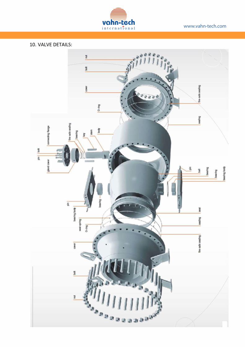
10. VALVE DETAILS:
www.vahn-tech.com

www.vahn-tech.com
11. MAINTENANCE PROCEDURES:
CAUTION For your safety, it is important that these precau s be taken before removal of the valve from the line or before dismantling.
De-pressurize the line before removi g.Wear prot ing or equipment appropriate for the line . Ensure cavity pressure is relieved.Cycle the valve several antling to relieve pressure completely
11.1.
11.1.1.
11.1.2.
Gear stopper adjustment procedure
Loosen the stoppers to allow addi rota lve stem.
Open the drain valve in the center cavity located at the bo ove ground valves and onthe extension housing for buried valves.
11.1.3.
11.1.4.
The pressure will be released from the center cavity of the valve.
vent/drain (except for the leakage past the seat), rotate the valve in either dire m to locate a point where the leakage stops.
11.1.5. Rotate clockwise and an clockwise to locate two points where the leakage begins. Mark both the ons and operate the valve to a on halfway between the two marks.
11.1.6. Close the vent valve. Actuate the valve exactly 90° and set the other stop.
11.2.
CAUTION It is desirable that the valve (both bore and cavity) be relieved of pressure prior to sealreplacement. If it is not possible, get in touch with or their au-thorised service representa v n on.
11.2.1.
11.2.2.
Ensure that no pressure is trapped inside the valve and exercise the following steps for replacing the stem seal.
Mark the open and close posi ve it; preferably without disturbing the mechanical stopper screws in the gearbox.
11.2.3.
11.2.4.
11.2.5.
11.2.6.
Remove the key and its retainer screw and washer, if provided.
Loosen all the hexagonal cap screws which holds the gland and remove the gland from its place.
Clean the packing area.
Inspect the stem bore on body and stem for damage like scratches and correct them by rubbing with emery sheet.
11.2.7.
11.2.8.
Insert a new set of graphite packing and place the gland over it.
Tighten cap screws uniformly to a torque depending on the size of the screw.
Stem seal replacement procedure

www.vahn-tech.com
11.2.9. Pressurize the system and check for leak using soap bubbles.
11.2.10. Re-assemble the key and gear unit. Ensure that the toppers are correct. (Refer sec-11.1 for co on)
11.3. Secondary sealant injec n procedure – Stem
Fig.5. Stem Sealant Injec on
11.3.1.
11.3.2.
11.3.3.
11.4.
Remove grub screw (Fig.6.)
Insert graphite based sealant.
Place the grub screw and ening will pressurize the sealant in the stem.
Secondary sealant injec n procedure – Seat ring
Fig.6. Seat Sealant Injec on
Before injec ng sealant into the valve, ensure the valve is fully open or close.
ealant shall be charged using a sealant gun. 11.4.1.
11.4.2. ant on the sealant injec e) (Fig.7.) and charge the sealant.
11.4.3. While c mall angle (say 10°) and return it back to its original

www.vahn-tech.com
11.4.4.
11.4.5.
Remove the gun. The check valve will prevent the back of the sealant.
Check and ensure that there is no leakage across the seats.
EXPERTS NOTE Sealant to be used is Nordstrom 1033 sealant. This is available in bulk, gunpak and grades (generally for stem sealant). This can be used for liquid and gaseous alipha c hydrocarbon service suitable for gasoline, kerosene, fuel oils, crude di l, and natural gas at a temperature range of –40°C to + 260°C. For other spec c consu
CAUTION Nordstrom 1033 sealant is not suitable for use with arom c solvents, strong acids andalkalis, and steam.
11.5. Dismantling procedure
CAUTION be changed. Ensure they
are available.
11.5.1.
11.5.2.
Depressurize the line and open the valve to drain the line.
Before removal from the line, cycle (open and close) the valve to relieve residual pressure in thebody cavity.
11.5.3.
11.5.4.
11.5.5.
Valves shall be slung properly before loose nge bolts.
Place the valv or base and transport to the repair shop.
Before dismantling, cycle (open and close) the valve se lwater.
11.5.6.
11.5.7.
11.5.8.
11.5.9.
Close the valve completely and remove handle/gear unit.
Secure body in a suitable clamping device, without damaging it.
Loosen the body-body connector interfac ng and remove the body connector.
Remove the seat ring from the body and body connector.
11.5.10. Li the ball/bearing block sub assembly using a nylon rope or using eye-bolts (for large sizes). If the ball is intended for reuse, place it on the seat ring and suitably cover it so that it is not damaged.
11.5.11. Remove the key from the stem.
11.5.12. Remove gland bolts from the valve body. Remove the packing and clean the packing area. Take care not to damage sealing surfaces on body or gland.

www.vahn-tech.com
11.5.13. Carefully push valve stem down into the valve body and withdraw it through the open end and re-move the thrust bearing from stem.
CAUTION
Before removal of the valve, ensure that the line is fully depressurize.
Improper handling may cause ball / seat damage or on of stem or seat, which wil i lve.
Ensure that the dismantled components are kept in a clean place so that there will be nodamage to the components.
11.6. Assembly Procedure
11.6.1. Inspect and clean all parts (Fig. 7.) to make sure they are free of dust, grit or other material. New set of o-rings and seals shall be used once the valve is dismantled.
11.6.2.
11.6.3.
Apply a good lubricant com service,such as silicone grease, to bearing blocks, seats, seal, ball and stem.
Refer to the exact seat ring design, as per the general assembly drawings and assemble it according-ly.
Fig.7. Major components of valve before assembly
CAUTION In case of crimped seat design, if the seat is damaged, the seat ring / housing shall not be
reused. New seat ring assemblies shall be procured.
11.6.4. Assemble the seat sealing elements to the seat rings.

www.vahn-tech.com
Fig.8. Seat ring assembly inserted into the body
11.6.5.
11.6.6.
Place a seat spring in the body bore and place one seat ring into the body as shown in Fig. 8. Insert the seat ring assembly so that it rests on the seat spring. Care should be taken so that the o-ring does not fall out or get misaligned inside the valve.
Assemble thrust bearing, o-ring and backup ring on the stem. Carefully insert upper end of stem into body of valve (Fig.9.) and maneuver into the opening in top of valve.
Fig.9. Stem being inserted into the body
11.6.7. Assemble packi sec on 11.2.6 to 11.2.8. Do not ten the cap screws now. (Fig.10.)
Fig.10. Gland packing inserted into the body
11.6.8.
11.6.9.
Assemble the thrust washer and bearing blocks onto the ball. Check if the clearance between the bearing block and ball is minimum ( i.e., it is not very loose). If it is not so the trunnion bearings in the bearing block have to be changed. Make s pins in the bearing lock are in po-
.
Rotate stem so that stem up axially with the valve and ball and bearing blocks can be fully inserted.
11.6.10. Place ball-bearing block assembly into the body (Fig.11.).

For small sizes For large sizes (using eye-bolts)
Fig.11. Ball-bearing block assembly inserted into the body
11.6.11. Place second seat spring in the body connector and insert the seat ring (Fig.12.)
Fig.12. Seat ring being inserted
into the connector
11.6.12. Place the body seal in the body and place the connector in such a way to locate the dowel pins,pressed into the bearing blocks, on the holesprovided in the body. (Fig.. 13)
Fig.13.Connector being placed
on the body.
11.6.13. Tighten the interface he sec A2. (Fig.15.)
Fig.14.Valve n ed
using a torque wrench
11.6.14. Place the key in the stem slot and retain it with the washer and bolt.
11.6.15. Fix the gear unit / handle onto the valve stem. (Fig.15.)
Fig.15.
on valve.
www.vahn-tech.com
www.vahn-tech.com
EXPERTS NOTE
11.6.16. In case the drain and vent plug assemblies are dismantled, clean the threads of the plugs and assemble the plugs. Ensure that the sealant injectors are assembled on the threaded sealant charging holes.
11.6.17. Cycle valve open and close to turn ball slowly with a gentle back and forth mo , building gradually to a full quarter turn. By rota ly, the seat lips will assume a permanent seal shape against the ball and prevent damage to the seals.
sembly, the valve shall be tested for leakage across the seats and through the stem seals. iven for handli leaning a n and 6 shall be
strictly followed.
CAUTION
will a ect sealing and opera torque of the valve. Faulty installa ad to valve and/or pipeline damage.
are changed once they are removed from the valve. Avoid contact with the valve closure element during cycling.
12. SPARES & SEALANTS
12.1. Spares
12.1.1. Following spares may be maintained for quick repairs / emergencies:
12.1.1.1. One so seal kit comprising of O-rings, backup rings , nylon insert, gland packing and gasket
12.1.1.2. For valves in prolonged servic to the above, one set of bearings and thrust washers may be maintained.
12.2. Sealants
12.2.1. S a able seat and stem sealants may be maintained for charging to avoid pas-sing of media across valve seats or valve stem seals, as an emergency mean g leakage.
ded Trunnion Mounted Ball Valves are completely sealed type valves. These valves are welded together using submerged arc welding techniques to provide good quality, leak resistant welds s welded valves can- not be dismantled at site and hence the service ability of these valves is restricted to re- placements of stem seals and sealant i on at seats and stem seals for leak arrest /emergency shut .
Improper handling may cause ball/seat damage or d on of stem or seat, which

APPENDIX A
TECHNICAL INFORMATION
A1. References
Pressure-Temperature Ra :
API 6D ASME B 16.34
n es ( ate-, - and check va ves. ends
Face t face dimens ns:
API 6D eASME B 16.10 BS 2080
Face-t -face and end-t -end dimensi s ves e- face, centre-t -face, end-t -end and centre-
i t eum, pet hemic a dustries
nnec :
ASME B16.5 ASME B16.47 ASME B16.25
e NPS 224) Lar e diam u 60)
ends
Fire Test:
API 6FA API 607
Speci ca f r Fire Test f V vesFire Test f r S eated Quarter-Turn va ves
A n nce & .
The t s ce f ssi f is y the sc f this m . ver, th ed is ex a
in the s ce s in Fi 17. This s in c rrect f the maparts.
A2.2. Us c t s s in the same se uen i
n ts in the se uence sh the same way.
A2.4. The se nce e ckwise ar p .
n ec y, in the same se nce.
www.vahn-tech.com

A2.6. Ensure the recommended torque i
orque Values (Inch series)
B7/B7M/L7/L7M/B16
/45/ 63/8/ 6/2
9/ 65/8 00 90 b
3/4 90 0 b
/8 290 260 b
390 4 0 b
. /8 5 0 260 b
. /4 800 630 b
.3/8 0 50 b
. /2 400 950 b
.5/8 800 200 b
.3/4 2300 500 b
. /8 2800 850 b
2 3400 2250 b
2. /4 4900 3250 b
5560
TORQUE a , lbf. (B8/B8M)
CL.2
THREAD SIZE, in
60
2030
www.vahn-tech.com

Table 3. Tightening Torque Values (Metric series)
THREADSIZE
TORQUEIN Nm (+20%)
THREADSIZE
TORQUEIN Nm (++ 20%)
M4 2 M30 9433M5 4 M33 12662M6 7 M36 16336M8 18 M39 21009M10 34 M42 26228M12 58 M45 32991M14 92 M48 40229M16 140 M52 49666M18 196 M56 62777M20 273 M60 78000M22 375 M64 95551M24 473 M70 126440M27 688 M72 130001
www.vahn-tech.com

www.vahn-tech.com
CAUTION
APPENDIX B
SPECIAL CONSIDERATIONS IN VALVES WITH EXTENDED STEM
In valves with extended stem, do not sling around pip lant on, while handling. See Fig.19.
Through out the install ess, support for the extended stem (housing) should be maintained.
st xtension column with com event internal corrosion, if required. This can b ugh the opening in the extensio n column which are plugged with a 3/8” NPT plug. When the plug is assembled, ensure that the threads of the plug are not damaged.
Check whether the sealant charging pipes are connected properl ith sealant.
Fig.18. Handling a welded end valve with an extended stem
While this informa is presented in good faith and believed to be accurate, does not guarantory results from reliance up tained herein is to be construed as a warranty or guarantee, expressed or implied, the performance, merchantability, tness or any other ma to the products, nor as a recomm to use any product or process in con t with any patent. reserves the right, without n r impro ve the designs or speci ca s of the products described herein.

www.vahn-tech.com
#2906-15 Fort York BoulevardToronto, Ontario, M5V 3Y4, Canada
Tel/Fax: +1 416 342 0001


