Embed Size (px)
Citation preview

IBALL LOCK MOUNTING SYSTEM METRIC DIMENSIONS
www.jergensinc.com
Internet Catalog: www.jergensinc.com • Email: [email protected] • Telephone +1 216 486-5540 • Fax +1 216 481-6193 I.1
Ball Loc kTM
MountingSystem
I Ball Lock Mounting System
FAQ ..................................................I.4-5
Multi-Purpose Subplates .....................I.6 Fixture Plates...............................I.7Pre-Machined Subplates .....................I.8 Fixture Plates...............................I.9Quick Change Kits .............................I.10
Ball Lock T-Columns ..........................I.11
Ball Lock 4-Sided Tooling Columns ...I.12
Standard Subplates and Fixture Plates for Tooling Columns ...........................I.13
Ball Lock™ For Rotary Indexers........I.14
Building a System ..............................I.15
Locating and Clamping Shanks .........I.16
Receiver Bushings & Liners ..............I.17
Accessories .......................................I.18

I BALL LOCK MOUNTING SYSTEMMETRIC DIMENSIONS www.jergensinc.com
I.2 Jergens, Inc. • Jergens Way • 15700 S. Waterloo Road • Cleveland, Ohio 44110-3898 USA
The Ball Lock Mounting System is used as a Quick Change Solution on the following:• CNC Machines• Palletized Fixtures• Stamping• Fabricating• Injection Molding• Packaging Machines• Assembly Machines• EDM• Robotics• Welding Fixtures

IBALL LOCK MOUNTING SYSTEM METRIC DIMENSIONS
www.jergensinc.com
Internet Catalog: www.jergensinc.com • Email: [email protected] • Telephone +1 216 486-5540 • Fax +1 216 481-6193 I.3
Accurately Locate and Lock Fixture Plates to Subplates in Seconds...
...With No Indicating Required
CNCMachine Base:Drilling and reaming forged part.Previous Set Up Method:Fixture plate located with dowel pins bolted to machine base. Fixture plate and parts indicated.Previous Set Up Time:7 minutesSet Up Using Ball Lock System:Parts are pre-mounted on fi xture plate, which is then mounted to machine base using Ball Lock shanks. No need to indicate.Set Up Time with Ball Lock System:60 seconds
Two-Sided Tombstone:Drilling and tapping cylindrical bodies.Previous Set Up Method:Fixture located and bolted to tombstone. Had to be indicated.Previous Set Up Time:12 minutesSet Up Using Ball Lock System:Fixture plate mounted and located with Ball Lock shanks. No need to indicate.Set Up Time with Ball Lock System:45 seconds
CNC Vertical Machining CenterMachining aircraft valve partsPrevious Set Up Method:New Project. New Machine.No Prior History.Previous Set Up Time:New Set Up.Set Up Using Ball Lock System:Using Ball Lock Jig Saw Plate on Multi-Purpose Subplate enables operator to mount two more vises on the fi xture. No indicating needed.Set Up Time With Ball Lock System:80 seconds setting up six vises.
00:45
00:6001:20
Lean Manufacturing and Set Up Reduction Applications
Machining Cast PartPrevious Set Up Method:Located part with dowel pins, bolted part to tombstone fi xture. Indicated part to zero datum point.Previous Set-Up Time:15 minutesSet Up Using Ball Lock System:Mount parts to fi xture plate while machining other parts. Mount fi xture plate to tombstone using Ball Lock shanks. No indicating required because system provides +0.013mm repeatability.Set Up Time With Ball Lock System:60 seconds
00:60

I BALL LOCK MOUNTING SYSTEMMETRIC DIMENSIONS www.jergensinc.com
I.4 Jergens, Inc. • Jergens Way • 15700 S. Waterloo Road • Cleveland, Ohio 44110-3898 USA
LocatesThe Ball Lock™ System accurately positions your workpiece...to within ±0.013mm repeatability, minimizing the need to indicate your fi xture.
Q. What is the Ball Lock System?
A. A means of locating and locking two fl at surfaces together. These are usually a fi xture plate and a subplate.
Q. How does it locate the plate?
A. It locates in the same manner as locating pins. In other words, there are two precision bores (receiver bushings) located on two precision pins (shanks).
Q. How many shanks (pins) do I need to locate the plate or part?
A. Two shanks are the maximum needed to locate. Anything more is a hindrance rather than a help. (This also applies to locating pins.)
Q. How does it lock?
A. The Ball Lock system achieves its holding force by a combination of force generators. A threaded screw exerts force onto a center ball which, in turn, directs this force onto three balls that register on a taper seat.
Q. How many do I need to lock the part?
A. This would depend on the particular application, but in most cases, we would recommend that at least four shanks be used (two shanks to locate and lock, and two shanks to lock only).
Q. If I should only locate on two shanks, how do I install the other two shanks without causing interference?
A. This is accomplished by only using liner bushings for the locating shanks and drilling a clearance hole (shank diam-eter plus approximately 0.76mm) for the remaining shanks.
Q. How close a repeatability can I expect?
A. If the center distance between the two locating holes (receiver bushings) is held to ±0.005mm tolerance, and two primary liner bushings are used, then repeatability of ±0.013mm can be maintained.
Q. What is the difference between the primary and the secondary liner bushings?
A. The only difference between the primary and the secondary liner bushings is that the secondary liner bushing has an oversized I.D. to
The Ball Lock Mounting System is designed to speed accurate locating and locking of fi xture plates and subplates. The system consists of three parts: a Locating Shank, a Liner Bushing, and a Receiver Bushing. Using the Ball Lock Mounting System is a simple three step process. Install receiver bushings in your machine table or subplate, and liner bushings in your fi xture plate; then
insert the locating shanks through the liners and into the receivers to provide accurate location. A couple of turns of the set screw in each of the locating shanks provides positive holding force. Eighteen locating shanks, two types of receiver bushings, and two types of liner bushings are available to suit your individual requirements.
It is recommended that the use of the Ball Lock Mounting System for locating and clamping of fi xture plates be incorporated in a systematic process. All fi xture plates should have two locating points positioned as far apart as possible. There is no advantage to having more than two locating points. If more than two fl anged shanks are
LocksThe Ball Lock System securely holds fi xture plates to subplates with up to 9000kgs. of hold-down force per shank.
Most Commonly Asked Questions

IBALL LOCK MOUNTING SYSTEM METRIC DIMENSIONS
www.jergensinc.com
Internet Catalog: www.jergensinc.com • Email: [email protected] • Telephone +1 216 486-5540 • Fax +1 216 481-6193 I.5
required to provide additional hold- down force, omit liner bushings in the additional holes in the fi xture plate and allow 0.76mm over the nominal size. The additional clearance will insure that these holes have no infl uence on the locating holes.How Accurate Does Your Positioning Have to Be?
The center distance of the receiver bushings in the machine table, tombstone, or subplate should be as accurate as possible (±.005mm recommended). Accurate location will insure a sound base for interchangeability of numerous fi xture plates. For accurate repeatability within 0.013mm of true position, both of the liner bushings in the fi xture plate should be primary liners and the center
distance tolerance should be ±0.005mm. For slightly less accurate repeatability (within 0.04mm of true position), use one primary and one secondary liner with a center distance tolerance of ±0.03mm.
Back Mount Bushing
Ball Lock Shank
Fixture Plate
Liner Bushing Ball Lock Shank Liner Bushing
SubplateDrilled Hole
Slip Fit Hole Press Fit Hole Socket Head Cap Screws (3)
Face Mount Bushing
Fixture Plate
Mounting Method With Back Mount Bushing
accommodate the wider center distance tolerance on your fi xture.
Q. Is there a preferable location for the liner bushing?
A. The location of the liner bushing is not critical, but in order to be consistent, we recommend that wherever possible, locate the liner bushings at bottom left and at top right.
Q. What are the advantages of using the Ball Lock System over the conventional method of dowel pins and cap screws?
A. Both locating and locking are accomplished in the same motion. Two and one half turns are the maximum needed to lock (whereas a M12×1.75 cap
screw with one and a half diameters of thread engagement would need ten turns to lock). On CNC machines, the repeat-ability of fi xture locations makes indicating of the fi xture unnecessary.
Q. If I need to recess the fi xture plate in order to have a clear surface, what do I have to do?
A. Counterbore the fi xture plate to a diameter large enough to allow easy removal of the shank. Note: The thickness of the plate section under the head of the shank is critical! It must conform to plate thickness recommended in the catalog.
Q. What if my plate is thinner than the recommended thickness?
A. It is possible that by adjusting the
depth of the counterbore for the receiver bushing, you can still use the Ball Lock System. If there are any questions on this type of application, please call +1 216 486-5540.
Q. Can I use the shanks in a heated environment?
A. The shank is made of alloy steel, heat treated to 40-45Rc and should stand temperatures up to 200°C. However, the “O” Ring that retains the balls could disintegrate.
Note: Be aware that thermal expansion of your plate could affect the center distance tolerance and repeatability.
Mounting Method With Face Mount Bushing
Counter-Bored Hole
Machine Table or Subplate

I BALL LOCK MOUNTING SYSTEMMETRIC DIMENSIONS www.jergensinc.com
I.6 Jergens, Inc. • Jergens Way • 15700 S. Waterloo Road • Cleveland, Ohio 44110-3898 USA
The Jergens Multi-Purpose Subplate is ideal for adapting your machine tools to accommodate most fi xtures. Its versatility, coupled with the quick change capabilities of the Ball Lock Mounting System, makes it ideal for any size production run.
1000
50
200
425 425
300 300
425
300
150
(8) 25MM FACE MOUNTBUSHINGS I NSTALLED
(18) 20MM FACE MOUNTBUSHINGS I NSTALLED
16MM BORED HOLEFOR SINE FIXTURE KEYS
(2) PLACES
Multi-Purpose Subplates • Material: FreMaxTM 15 Steel or Equivalent• Thickness: 30mm• Thickness Tolerance: ± 0.1mm• Weight: 130 Kg• Subplate will accept combinations of fi ve different standard Ball Lock Fixture Plates• Includes installed Ball Lock Receiver Bushings• Ideal solution to increase production
Part Number 59112
1000x500 Multi-Purpose Subplate
Fixture Plate Options for Multi-Purpose Subplates – Aluminum or Steel
* See next page for dimensional data on fi xture plates. Part numbers shown for aluminum plates, also available in steel. ** Counterbored to 25mm at mounting holes.
Number of Fixture Receiver Required Number Plates That Mount Bushing Receiver Ball Lock of Shanks Fixture Plate* Thickness of on Multi-Purpose Center Bushing Shank Required Per Part Number Fixture Plate Subplate Distance Size Part Number Fixture Plate
58713 (350 x 350) 20mm 2 300 x 300 20 mm 49652 4Fixture Plate 58715 (400 x 400) 20mm 2 300 x 300 20 mm 49652 4Fixture Plate58801 (400 x 400) 30mm** 2 300 x 300 20 mm 49652 4Modular Grid Plate58706 Jigsaw 20mm 4 300 x 200 20 mm 49652 3Interlocking Plate 58727 (500 x 500) 25mm 2 425 x 425 25 mm 49662 4Fixture Plate

IBALL LOCK MOUNTING SYSTEM METRIC DIMENSIONS
www.jergensinc.com
Internet Catalog: www.jergensinc.com • Email: [email protected] • Telephone +1 216 486-5540 • Fax +1 216 481-6193 I.7
Fixture Plates for Use on Multi-Purpose Subplate
Jigsaw Interlocking Plate
350x350 Fixture Plate
300
150 200
200
250
CLEARANCE HOLE FORHOLDDOWN
(2) 20MMPRIMARY LINERSINSTALLED
Aluminum PlatePart Number
58713
500
500
425
425
212.50
CLEARANCE HOLESFOR HOLDDOWN
(2) PLACES
16MM BORED HOLEFOR SINE FIXTURE KEYS(2) PLACES
(2) 25MMPRIMARY LINERS
INSTALLED
500x500 Fixture Plate
• Material: Alca Plus Cast Aluminum or FreMax 15 Steel• Thickness: 25mm• Thickness Tolerance: ±0.1mm• Weight: Aluminum 18 Kg, Steel 52 Kg
400x400 Modular Grid Fixture Plate
• Material: FreMax 15 Steel• Thickness: 25mm• Thickness Tolerance: ±0.1mm• Weight: 35 Kg
400x400 Fixture Plate
Steel PlatePart Number
58813
Aluminum PlatePart Number
58715
Steel PlatePart Number
58815
Aluminum PlatePart Number
58727
Steel PlatePart Number
58801
Steel PlatePart Number
58827
• Material: Alca Plus Cast Aluminum or FreMax 15 Steel• Thickness: 20mm• Thickness Tolerance: ±0.1mm• Weight (350mmx350mm): Aluminum 6 Kg, Steel 20 Kg• Weight (400mmx400mm): Aluminum 8 Kg, Steel 25 Kg
• Material: Alca Plus Cast Aluminum or FreMax 15 Steel• Thickness: 20mm• Thickness Tolerance: ±0.1mm• Weight: Aluminum 4 Kg, Steel 12 Kg• For use with straight base 100mm or 150mm vises• Unique design minimizes center distances between vises allowing for more parts on a production run• Easily mounts to Multi-Purpose Subplate using the Ball Lock
Mounting System• Adaptable to nesting small parts
300
300
50TYP
400
400
CLEARANCE HOLESFOR HOLDDOWN(2) PLACES
(2) 20MMPRIMARY LINERSINSTALLED
16MM X 6MM DEEPCOUNTERBORE
M12 X 1.75TAPPED HOLE
300
300
150
CLEARANCE HOLESFOR HOLDDOWN
(2) PLACES
16MM BORED HOLEFOR SINE FIXTURE KEYS(2) PLACES
(2) 20MM PRIMARY LINERS
INSTALLED
Aluminum Plate Steel Plate Part No Part No 58706 58806

I BALL LOCK MOUNTING SYSTEMMETRIC DIMENSIONS www.jergensinc.com
I.8 Jergens, Inc. • Jergens Way • 15700 S. Waterloo Road • Cleveland, Ohio 44110-3898 USA
Equipped with twelve installed 20mm receiver bushings to easily locate and mount the following fi xture plates:
Equipped with four 20mm receiver bushings for use with 350x350 or 400x400 (mm) fi xture plates. Ideal for horizontal machining centers or multiple pallet machining centers.
• Material: FreMax™ 15 steel plate• Flat within 0.03 mm• Thickness: 25mm• Thickness tolerance: ±0.1mm• Weight: 37 Kg.
400
400
300
300
150
(4) 20MMFACE MOUNT BUSHINGS
INSTALLED
16MM BORED HOLEFOR SINE FIXTURE KEYS(2) PLACES
250
300
150
300
650
400
325
25
150
(12) 20MMFACE MOUNT BUSHINGSINSTALLED
16MM BORED HOLEFOR SINE FIXTURE KEYS(2) PLACES
To make the job easier, the Ball Lock Quick Change Kit includes all components needed in a single package. See page I.10 for details.
Pre-Machined Ball Lock Steel Subplates400 x 400 Subplate
650x400 Dual Station Subplate
Part Number 59111
• Ideal for vertical machining centers.• Thickness: 25mm• Weight: 58 Kg.
Part Number 59101
Number Plate Part of Fixture Width and Number Plates Length(mm) 58713 1 350x350 58715 1 400x400 58711 2 300x350
Equipped with four installed 16mm receiver bushings and 12mm mounting holes. Used with the Bridgeport™ style fi xture plate. • Thickness: 20mm• Weight: 15Kg
˚˚˚
˚˚˚
˚˚˚
˚˚˚
250
63.5
63.5
375
300 20
200
16MM FACE MOUNT BUSHINGS
Part Number 59121
250x375 Bridgeport™-Style Subplate
12MM DIA. FOR MOUNTING TO TABLE (4) PLACES
16MM BORED HOLES FOR SINE FIXTURE KEYS (2) PLACES

IBALL LOCK MOUNTING SYSTEM METRIC DIMENSIONS
www.jergensinc.com
Internet Catalog: www.jergensinc.com • Email: [email protected] • Telephone +1 216 486-5540 • Fax +1 216 481-6193 I.9
• Pre-machined to close distance tolerance
• Ensure ±0.013mm repeatability of the Ball Lock System
• Includes pre-installed primary liners
• Reduces fi xture set-up and assem-bly time
• Provided with 16mm reamed holes for sine fi xture keys
• Ideal for horizontal or vertical machining centers, Bridgeport™ style machines, or multiple pallet machining centers
• Material: Cast Aluminum* or FreMax 15 Steel• Flat within 0.1 mm• Thickness tolerance: ±0.1mm• 6061–T-651 plates, fl at within 0.03mm available upon request
Pre-Machined Ball Lock Fixture Plates
Custom Sizes AvailableJergens will make any size Ball Lock fi xture plate or subplate to your specifi cations. Call +1 216 486-5540 for further information.
58706 4.5 58806 15 250 x400 20 20 58711 5 58811 16 300 x350 20 20 58713 6 58813 20 350 x 350 20 20 58715 8 58815 25 400 x 400 20 25 58727 18 58827 52 500 x 500 25 25 58801 35 400 x 400 25 20
Plate Widthand
Length(mm)
Note: Each plate has two primary liners installed.
Plate
Thickness(mm)
Ball Lock
Shank Size(mm)
Part Number
Weight Weight
Pre-Machined Ball Lock Fixture Plates
Aluminum (Kgs) Steel (Kgs)
200
16mm Bored holes for sine fi xture keys(2) places
16mm Primary liners (2) places
250x375 Fixture Plate Bridgeport™ Style
20mm Primary liners (2) places
16mm Bored holes for sine fi xture keys(2) places
250
150
300x350 Fixture Plate
Aluminum PlatePart Number
58711
Steel PlatePart Number
58811
300
Aluminum PlatePart Number
58731
Steel PlatePart Number
58831
300
100
250
375
Clearance Hole For Holddown(2) places
300
Clearance holes for holddown (2) places
350

I BALL LOCK MOUNTING SYSTEMMETRIC DIMENSIONS www.jergensinc.com
I.10 Jergens, Inc. • Jergens Way • 15700 S. Waterloo Road • Cleveland, Ohio 44110-3898 USA
Quick Change Kits
Part No. Kit Includes
59002 2 - 58715 (400x400x20) aluminum fi xture plates with 20mm liner bushings installed 1 - 59101 (400x400x25) steel subplate
with receiver bushings installed 4 - 20mm Ball Lock Shanks (49651)
Everything You Need to Change Fixtures in Less Than One Minute
The Jergens Ball Lock™ Quick Change Kits speed fi xture changeover in all types of manufacturing operations. Each kit includes two aluminum fi xture plates with liner bushings installed; one steel subplate with receiver bushings installed; and four 20mm Ball Lock shanks with working loads of 10 KN. each. While one fi xture plate is on the machine, the operator can load parts on the other. This minimizes downtime for true set-up reduction.To enable the subplate to be mounted on a slotted table without the need to indicate the subplate, sine fi xture keys can be used. The sine fi xture key reamed holes are oriented parallel to the receiver bushings on the subplate and to the liner bushings on the fi xture plate. These also allow the fi xture plate to be mounted on a toolroom mill without the need to indicate it. This is extremely useful when machining location points on your fi xture.
Steel Subplate
20mm Ball Lock Shank
16mm Bored Hole for Sine Fixture Keys
16mm Bored Hole for Sine Fixture Keys
Receiver Bushings (4) places
Primary Liner Bushings (2) places
AluminumFixture Plate Quick Change Kits
Custom Kits AvailableJergens manufactures ready to use kits includingBall Lock subplate and fi xture plates. For a special kit tailored to your CNC machine, please provide:Name and Type of Machine __________________Travel of Machine Table (x, y, z) ______________Dimensions of Machine Table (x and y) _________Maximum Weight allowed on Machine Table _____T-slot Width and Center to Center Distance _____

IBALL LOCK MOUNTING SYSTEM METRIC DIMENSIONS
www.jergensinc.com
Internet Catalog: www.jergensinc.com • Email: [email protected] • Telephone +1 216 486-5540 • Fax +1 216 481-6193 I.11
Part O P Fixture Plate Sub Plate Number M N (mm) (mm) Part Number Part Number 69151 125 90 20 20 58717 59102 69161 137.5 90 25 25 58745 59103 69171 137.5 90 35 25 58746 59104
Cast Iron T-Columns WithBall Lock Receiver Bushings Installed
• Material: Class 40 Meehanite cast iron• Also available in Aluminum• Ball Lock Receiver Bushings and Liners installed• Provides accurate fi xturing base for CNC machining centers• Perpendicularity is 0.02 mm per 250 mm
Use Hoist Ring 23462 for lifting and handling – Order separately.
Pre-Machined Ball Lock T-Columns
Part Wt. Number C D E F G H I J K L (kgs) 69151 410 25 400 400 350 350 350 350 100 500 190 69161 560 25 500 500 475 425 425 425 120 650 310 69171 660 40 630 630 575 550 525 525 100 750 500
Note: Window sections are also available on T-Columns. Window size and location (Q and R Dimensions) to be specifi ed by customer.
Custom Sizes AvailableWe are able to quote you on your special requirement columns, pre-machined with or without the Ball Lock components installed in place. Call +1 216 486-5540 for design specifi cation information.
Engineering ChangesProduct improvement is a continuing process at Jergens. Specifi cations and engineering data are subject to change without notice. If current information is critical to your design, it is suggested that you contact Jergens Technical Sales Department to verify any dimensions or specifi cations.
Dimensions continued from above.
M12
I BALL LOCK MOUNTING SYSTEMMETRIC DIMENSIONS www.jergensinc.com
I.12 Jergens, Inc. • Jergens Way • 15700 S. Waterloo Road • Cleveland, Ohio 44110-3898 USA
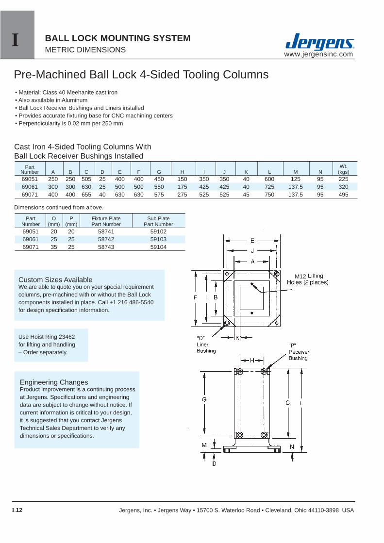
Part O P Fixture Plate Sub Plate Number (mm) (mm) Part Number Part Number 69051 20 20 58741 59102 69061 25 25 58742 59103 69071 35 25 58743 59104
Part Wt. Number A B C D E F G H I J K L M N (kgs) 69051 250 250 505 25 400 400 450 150 350 350 40 600 125 95 225 69061 300 300 630 25 500 500 550 175 425 425 40 725 137.5 95 320 69071 400 400 655 40 630 630 575 275 525 525 45 750 137.5 95 495
Cast Iron 4-Sided Tooling Columns WithBall Lock Receiver Bushings Installed
• Material: Class 40 Meehanite cast iron• Also available in Aluminum• Ball Lock Receiver Bushings and Liners installed• Provides accurate fi xturing base for CNC machining centers• Perpendicularity is 0.02 mm per 250 mm
Custom Sizes AvailableWe are able to quote you on your special requirement columns, pre-machined with or without the Ball Lock components installed in place. Call +1 216 486-5540 for design specifi cation information.
Use Hoist Ring 23462for lifting and handling– Order separately.
Pre-Machined Ball Lock 4-Sided Tooling Columns
Dimensions continued from above.
M12
Engineering ChangesProduct improvement is a continuing process at Jergens. Specifi cations and engineering data are subject to change without notice. If current information is critical to your design, it is suggested that you contact Jergens Technical Sales Department to verify any dimensions or specifi cations.

IBALL LOCK MOUNTING SYSTEM METRIC DIMENSIONS
www.jergensinc.com
Internet Catalog: www.jergensinc.com • Email: [email protected] • Telephone +1 216 486-5540 • Fax +1 216 481-6193 I.13
Receiver Thickness of Part Pallet Size For Tooling Size Subplate Wt Number (mm) Columns (mm) (mm) (mm) (mm) (Kgs) 59102 400 69151/69051 350 350 20 25 59103 500 69161/69061 425 425 25 30 59104 630 69171/69071 525 525 35 40
3050
125
Part Number Liner Fixture Plate For E F I J Size Thickness Aluminum (Kgs) Steel (Kgs) Subplate (mm) (mm) (mm) (mm) (mm) (mm) 58717 39 58817 117 59102 400 400 350 350 20 20 58727 83 58827 250 59103 500 500 425 425 25 25 58732 127 58832 381 59104 630 630 525 525 35 25
Fixture Plate Liner Fixture Plate For Tooling Size H G Size Thickness Columns (mm) (mm) (mm) (mm) (mm) 58741 30 58841 90 69051 250x500 150 450 20 20 58742 61 58842 183 69061 300x625 175 550 25 25 58743 85 58843 255 69071 400x650 275 575 25 25 58717 39 58817 117 69151 400x400 350 350 20 20 58745 90 58845 270 69161 500x550 425 475 25 25 58746 134 58846 402 69171 625x650 550 575 25 25
Fixture Plates for Standard Tooling Columns and T-Columns
Supplied with Ball Lock Liner Bushings installed.
Fixture Plates for Tooling Column Subplates
JE
I F
NOTE: Aluminum and steel expand at different rates. Please take this information into consider-ation when creating your own Ball Lock fi xture and subplates.
Supplied with Ball Lock Liner Bushings installed.
A
BB
A
Standard Subplates and Fixture Plates for Tooling Columns
Note: Mounting holes can be provided per customer specifi cation. Supplied with Ball Lock Receiver Bushings installed.
Standard Steel Subplates for Tooling Columns
Part Number
Aluminum (Kgs) Steel (Kgs)
A B
16mm Bored holes for sine fi xture keys (2) places
16mm Bored holes for sine fi xture keys(2) places
16mm Bored holes for sine fi xture keys (2) places
Receiver Bushings
Primary Liners
Primary Liners
5.45.4
Aluminum and Steel Expansion(per cm)
Diff
eren
ce b
etw
een
Alu
min
um a
nd S
teel
( m
m)
0.0015
0.00125
0.001
0.00075
0.0005
0.00025
02.8 8.4 11.2 14 16.8
Change in Degrees C
0

I BALL LOCK MOUNTING SYSTEMMETRIC DIMENSIONS www.jergensinc.com
I.14 Jergens, Inc. • Jergens Way • 15700 S. Waterloo Road • Cleveland, Ohio 44110-3898 USA
Ball Lock™ For Rotary IndexersProblem: Although your rotary indexer increases the versatility of a vertical machining center, it has one major limitation: set-up is so laborious and time-consuming that it limits the machine’s fl exibility. In many cases, folks dedicate their units to a single machine tool to avoid the agony of an extended set-up and changeover.
Jergen’s Solution: Our new Ball Lock Mounting System for Indexers provides a two-pronged solution.
First, Ball Lock mounting plates free up your machine tool for additional work by allowing a fast and accurate quick change of the complete indexer. No longer will you spend hours doing set up. The Ball Lock System does it in minutes, with repeatability at ±0.013mm. Low profi le, positive clamping, proven in over ten years of fi eld use.
Second, the Ball Lock System puts your fi xture plate change-overs into high gear. By mounting the round subplate to the indexer faceplate, you’ll “plug-in” new fi xtures in record time (less than 60 seconds).
Benefi ts:• Maximize indexer utilization• Eliminate lengthy set-ups• Accurate fi xture plate changover in seconds
Subplates and fi xture plates come with bushings pre-installed.
Ball Lock Subplate
Indexer Face Plate
Workpiece
Ball Lock Fixture Plate
Ball Lock Mounting Plate

IBALL LOCK MOUNTING SYSTEM METRIC DIMENSIONS
www.jergensinc.com
Internet Catalog: www.jergensinc.com • Email: [email protected] • Telephone +1 216 486-5540 • Fax +1 216 481-6193 I.15
Fixture Plate(mm) Part Ball Lock Ball Lock No. A B Thickness Liner Shank Weight(Kgs) 58707 200 150 20 16 49657 1.6 58708 250 200 25 20 49652 3.2 58709 300 250 25 20 49652 5.0
Subplate(mm) Part Ball Lock Center No. A B Thickness Receiver Hole Weight 59107 200 150 20 16 25 5.0 59108 250 200 25 20 50 9.6 59109 300 250 25 20 50 15.0Note: Equivalent system available in dimensions.
Building a System
Engineering ChangesProduct improvement is a continuing process at Jergens. Specifi cations and engineering data are subject to change without notice. If current information is critical to your design, it is suggested that you contact Jergens Technical Sales Department to verify any dimensions or specifi cations.
Standard Systems
Custom Systems
Indexer:
Make:
Model:
Diameter:
Light Duty or Heavy Duty:
Through Hole Bore:
Machine It Is Going On:
Make:
Model:
Weight Capacity:
Indexer Faceplate:
T-Slot Size:
Confi guration/Orientation:
or
Drilled Tapped Hole Size:
Confi guration/Orientation:
Material:• Fixture Plate: Alca Plus™ cast aluminum, ±0.1mm thickness tolerance• Subplate: FreMax™ 15 steel, ±0.1mm thickness tolerance

I BALL LOCK MOUNTING SYSTEMMETRIC DIMENSIONS www.jergensinc.com
I.16 Jergens, Inc. • Jergens Way • 15700 S. Waterloo Road • Cleveland, Ohio 44110-3898 USA
Locating and Clamping Shank Dimensions
ShankPart
Number B C D
Each Kit Includes:• Replacement Screw• Locking Balls• Drive Ball• O-Ring
Replacement KitsAny Ball Lock application requires at least two sets of shanks, receiver bushings and liners. The liners are placed into the fi xture plate to insure extremely accurate positioning. If more than two shanks are required (to provide additional hold down force), omit the liner bushing so that these additional holes will not interfere with your primary locating holes.
Fixture Plate
Thickness±0.13mm
ShankDiameter
(mm)A
• Material: Shank/Bushing, AISI 4340 Liner, 52100• Finish: Black Oxide• Heat Treat: Shanks, RC 40-45 Bushings, RC 50-54 Liners, RC 62-64
• Stainless Steel available in all sizes
Locating and Clamping Shanks
A
C
D
B
U.S. Patents: 3,498,653 4,135,418
See page I.18 for additional Shank styles and options.
• Operating Temperature Range: -30ºC to 200ºC
DiameterHeight
Head of ShankMaximum
Screw HolddownTorque Force(N.m) (KN)
Recommended Screw Holddown
Torque Force(N.m) (KN)
HexWrench Size
ForSet Screw
Repair KitPart
Number
496554965649657496584965149652496614966249671496724968149682496834968449691496924969349694
132020252025202520252025405020254050
13 16 20 25 30 35 50
6 8 10 10 13 13
20
22 32 40 45 50 60 75
27.634.636.541.539.544.544.049.049.054.051.056.071.081.064.069.084.094.0
3.3 5.3 13.3 30 44 68 88
1 3 4 9 15 25 50
2.5 3 3 4 5 6 10
499554995649957499584995149952499614996249971499724998149982499834998449991499924999349994
1.2 4.5 5.3 11 18 33 65
2.7 3.5 10 23 35 52 67

IBALL LOCK MOUNTING SYSTEM METRIC DIMENSIONS
www.jergensinc.com
Internet Catalog: www.jergensinc.com • Email: [email protected] • Telephone +1 216 486-5540 • Fax +1 216 481-6193 I.17
Back MountFace Mount
Back Mount Installation DimensionsFace Mount
1Cap Screws Supplied with Face Mount Bushings.
ShankDia.(mm)
BackMountPart
Number
ShankDia.(mm)
Face Mount Part
Number
ActualO.D.-0.01-0.02
ClearanceDrill
DiameterE
Two styles of receiver bushings are available. Installed bushings should be approximately 0.3mm below subplate surface.
Min.SubplateThickness
D
Bore+0.003+0.010
F
Depth+0.025 -0.025
G
TapSize &Depth1
H
Bolt CircleDiameter
3 PL Equally Spaced
Min.SubplateThickness
D
ActualO.D.+0.04+0.03
A
Depth+0.025 -0.025
B
C-Bore±0.15
C
Receiver Bushings
Face Mount BushingInstallation Instructions
Back Mount BushingInstallation Instructions
13162025303550
M4x0.7 x 7M4x0.7 x 7M5x0.8 x 9
M6x1.0 x 10M6x1.0 x 11
M8x1.25 x 17M10x1.5 x 18
49556495574955149552495534955449555
35374555607092
13.521.021.025.530.540.055.0
35374555607092
11.9111.9116.2120.3222.1522.9931.50
25293542485675
20202530354050
13162025303550
49566495674956149562495634956449565
20222835424867
6.927.248.74
10.5410.9512.5015.75
26293341495576
20202525303545
Note on Installation of Press Fit Liners & Back Mount Style Receiver Bushings: To alleviate the possibility of binding the shank in the bore, the maximum interference fi t between bore and bushing O.D. should not exceed 0.013 mm.
Liners Liner Dimensions
Liner O.D. +0.00- 0.01
Locating repeatability will determine if one primary and one secondary or two primary liners are needed. With two primary liners, repeatability of ±0.013 mm canbe maintained if the two holes for receiver bushings areheld to a centerline distance of ±0.005 mm tolerance.
Shank Diameter
(mm)
Fixture PlateThickness
+0.13- 0.13
498554985649857498584985149852498614986249871
19.04019.04025.04225.04235.04235.04235.04235.04245.042
13
16
20
25
30
132020252025202520
35
50
497724978149782497834978449791497924979349794
498724988149882498834988449891498924989349894
45.04245.04245.04245.04245.04263.54663.54663.54663.546
Max. CornerRadius 0.5mm
Max. CornerRadius 0.5mm
Generally, the face mount receiver bushing is utilized in blind hole applications (Slip Fit).
The back mount receiver bushing is used in through hole applications (Light Press Fit).
Primary Liner Secondary Liner
Part Number Part NumberI.D. I.D.
13.01
16.01
20.01
25.01
30.01
35.01
50.01
13.04
16.04
20.04
25.04
30.04
35.04
50.04
H - Tap 3 Holes Equally Spaced On Bolt Circle Dia.
497554975649757497584975149752497614976249771
252025405020254050

I BALL LOCK MOUNTING SYSTEMMETRIC DIMENSIONS www.jergensinc.com
I.18 Jergens, Inc. • Jergens Way • 15700 S. Waterloo Road • Cleveland, Ohio 44110-3898 USA
www.jergensinc.com
Sine Fixture Keys
Accessories
Locate subplates or fi xture plates to slotted machine tables without having to slot the plate. Available in sizes from 12mm to 32mm slots.NOTE: See page III.6 for dimensions.
Lifting HandlesFor easy handling of fi xture plate.
Tapered Caps and PlugsKeep debris out of your subplate’s receiver bushings when they are not in use. Polyethylene caps easily snap in and out.
Part Number33701
Packaged 10 per pack.
Receiver Bushing Part Diameter Number 13 49201 16 49202 20 49203 25 49204 30 49205 35 49206 50 49207
Fast Acting Ball Lock™ Shanks
Thumb Screw
Adjustable Handle
Ball LockShank
Diameter(mm)
FixturePlate
Thickness(mm)
Part Shank Slot Size Size Wt. Number A B C (kg)
39551 16 12 25 .04 39552 16 14 25 .05 39553 16 16 25 .05 39554 16 18 29 .05 39555 16 20 29 .06 39556 16 22 29 .06 39557 20 24 35 .07 39558 20 28 35 .10 39559 20 32 40 .10
RecommendedHole Diameter
16mm Shank Size:16.01 ± 0.01
20mm Shank Size:20.01 ± 0.01
FAST ACTING BALL LOCK SHANKS Shank with Shank with Thumb Screw Adjustable Handle Part Number Part Number Assenbly T-Screw Assenbly Handle
13 13 49655-S 43971 49655-H 34360 20 49656-S 43972 49656-H 34361 16 20 49657-S 43974 49657-H 34365 25 49658-S 43975 49658-H 34365 20 20 49651-S 43974 49651-H 34365 25 49652-S 43975 49652-H 34365 25 20 49661-S 43977 49661-H 34378 25 49662-S 43978 49662-H 34379 30 20 49671-S 43980 49671-H 34385 25 49672-S 43980 49672-H 34385 35 20 49681-S 43985 49681-H 34393 25 49682-S 43985 49682-H 34393

IIwww.jergensinc.com
II.1
PRODUCTION VISES METRIC DIMENSIONS
Internet Catalog: www.jergensinc.com • Email: [email protected] • Telephone +1 216 486-5540 • Fax +1 216 481-6193
II Production VisesIntroduction ..................................... II.2-3
VMC Solutions ........................... II.4 HMC Solutions............................II.5100mm Production Vises ................ II.6-7150mm Production Vises ................ II.8-9100mm Production Vise Columns 4-Sided ....................................II.10 3-Sided ....................................II.11 Indexer Systems ......................II.11150mm Production Vise Columns 4-Sided ....................................II.12 3-Sided ....................................II.13 Indexer Systems ......................II.13Production Vise Columns 12 Station Hex ..........................II.14 12 & 16 Station Multi-Quads.....II.15Hydraulic Production Vises ...............II.16 100mm .....................................II.17 150mm......................................II.18 Hydraulic accessories...............II.19Production Vise Jaws .......................II.20Accessories ......................................II.21Ball Lock™ Accessories ..................II.22

IIwww.jergensinc.com
II.2
PRODUCTION VISESMETRIC DIMENSIONS
Jergens, Inc. • Jergens Way • 15700 S. Waterloo Road • Cleveland, Ohio 44110-3898 USA
Jergens Production Vise SystemWhat does the system do?• It clamps and locates in one step.• It holds from 1 to 16 workpieces.• It provides single minute changeover times.• It saves you time & money.
What is a production vise?• A Quick Change Fixturing System for VMC’s & HMC’s.• A vise that acts like a fi xture.• A replacement for dedicated fi xtures.
Fastest Quick Change Jaw System
Maximum Jaw Machinability- Machine “Pockets” into the vise jaws, in the shape of your workpiece.Low profi le clamping mechanism allows for maximum jaw machining area.
Maximum Holding Power- Load the workpieces into the vise and machine as required. Machined jaws contoured to hold your workpiece.
150mm MonoQuad
100mm MonoQuad
Single station adapter plate included
Quick change reverseable soft jaws
Production Vise Columns2, 4, 6, 8, 12 and 16 station models available.
Multiple base designs to meet any requirement

IIwww.jergensinc.com
II.3
PRODUCTION VISES METRIC DIMENSIONS
Internet Catalog: www.jergensinc.com • Email: [email protected] • Telephone +1 216 486-5540 • Fax +1 216 481-6193
Jergens Production ViseFeatures and Benefi ts:
Fully machinable and reversible jawsBenefi t: More workholding fl exibility per jaw set
Easy to remove center fi xed jawBenefi t: Quick change over to single station vise for larger parts
Fastest quick change jaw systemBenefi t: Reduce set up times and parts change over
Wide/Full jaw travelBenefi t: Larger workpiece holding capacity
Multiple mounting base confi gurations availableBenefi t: Increased fl exibility and use with existing equipment and hardware
Fully sealed lead screw assemblyBenefi t: Lower maintenance and repair problems/cost
Rigid construction with hardened and ground steel railsBenefi t: High accuracy and repeatability
Chip and fl uid fl ow through baseBenefi t: Easier to keep clean, no more clogging

IIwww.jergensinc.com
II.4
PRODUCTION VISESMETRIC DIMENSIONS
Jergens, Inc. • Jergens Way • 15700 S. Waterloo Road • Cleveland, Ohio 44110-3898 USA
VMC Solutions
Indexer SystemsIndexer solutions can be customized to your requirements. Choose either three or four sided columns.
Production Vises -- Narrow BaseThe small footprint allows maximum density of vises on your fi xture or table. Best choice for applications where parts are held in multiple vises.
Multi-Vise FixturesMount multiple narrow body vises onto a single fi xture plate. Then mount the plate onto your machine table. Maximize your productivity by using the Jergens Ball Lock™ Mounting System.
Production Vises -- Universal Slotted BaseThe mounting fl ange has slotted holes to allow mounting on any machine table.
Production Vises -- Ball Lock™ BaseThe mounting fl ange is cut into a jigsaw pattern to allow vises to nest closely together. Designed for use with Jergens Ball Lock™ Mounting System.

IIwww.jergensinc.com
II.5
PRODUCTION VISES METRIC DIMENSIONS
Internet Catalog: www.jergensinc.com • Email: [email protected] • Telephone +1 216 486-5540 • Fax +1 216 481-6193
HMC Solutions
6-Sided Production Vise ColumnsMaximize the number of parts per load, while maintaining a small footprint. Available with bases to fi t directly onto your machine table or to a Ball Lock™ sub-plate.
4-Sided Production Vise Multi-ColumnsMultiple columns mounted on a single base provide 12 or 16 workstations. Available with bases to fi t directly onto your machine table or to a Ball Lock™ sub-plate.
4-Sided Production Vise ColumnsThese are the workhorses of the line. Available with bases to fi t directly onto your machine table or to a Ball Lock™ sub-plate.
3-Sided Production Vise ColumnsThe perfect solution for machining 3 plus sides of small parts on your HMC. Even large spindle noses won’t prevent getting close to the work. Allows for up to 240° workpiece accessability.
Multi-Vise Fixture Columns with Ball Lock™
Mount multiple narrow body vises onto a single fi xture plate. Then mount the plate onto your tombstone. Maximize your productivity by using the Jergens Ball Lock™ Mounting System.
IIwww.jergensinc.com
II.6
PRODUCTION VISESMETRIC DIMENSIONS
Jergens, Inc. • Jergens Way • 15700 S. Waterloo Road • Cleveland, Ohio 44110-3898 USA
30
10190
87.5
73 24
30
20 Max 2.5 380
176100
20 6
12Machinable
Area 56 64
100mm Production Vises
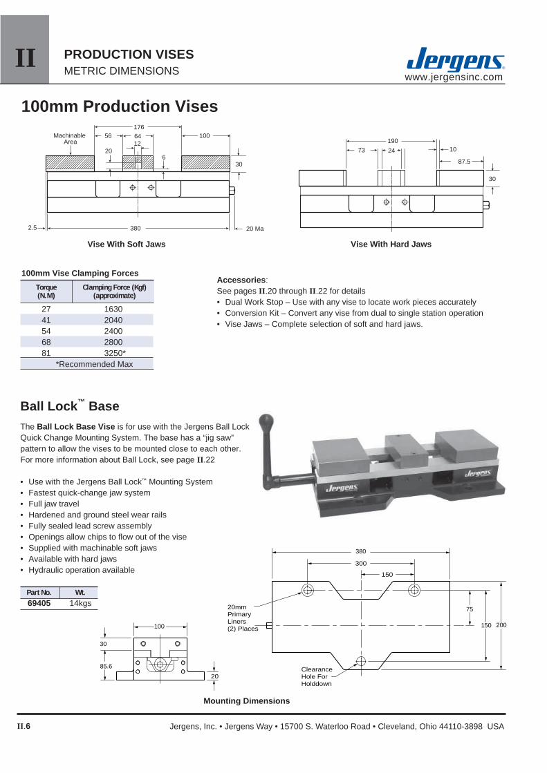
Ball Lock™ BaseThe Ball Lock Base Vise is for use with the Jergens Ball Lock Quick Change Mounting System. The base has a “jig saw” pattern to allow the vises to be mounted close to each other. For more information about Ball Lock, see page II.22
• Use with the Jergens Ball Lock™ Mounting System• Fastest quick-change jaw system• Full jaw travel• Hardened and ground steel wear rails• Fully sealed lead screw assembly• Openings allow chips to fl ow out of the vise• Supplied with machinable soft jaws• Available with hard jaws• Hydraulic operation available
Accessories: See pages II.20 through II.22 for details• Dual Work Stop – Use with any vise to locate work pieces accurately• Conversion Kit – Convert any vise from dual to single station operation• Vise Jaws – Complete selection of soft and hard jaws.
Vise With Soft Jaws Vise With Hard Jaws
Mounting Dimensions
75
150 200
380
150
300
ClearanceHole For Holddown
20mmPrimaryLiners(2) Places 100
30
85.6
20
100mm Vise Clamping Forces
Torque Clamping Force (Kgf) (N.M) (approximate)
27 1630 41 2040 54 2400 68 2800 81 3250*
*Recommended Max
Part No. Wt. 69405 14kgs

IIwww.jergensinc.com
II.7
PRODUCTION VISES METRIC DIMENSIONS
Internet Catalog: www.jergensinc.com • Email: [email protected] • Telephone +1 216 486-5540 • Fax +1 216 481-6193
13.5
150
63.5
80
150
52.5
Locating Holes16mm (4) Plcs
Mounting holesfor M12 SHCS (2) PLACES
175
12
12
120
50
100
75
125
40
25
Mounting HolesM10 Tap:(6) Plcs
Locating Holes16mm (4) Plcs For Sine Fixture Keys
Mounting Holes for M12 SHCS: (3) Plcs
12mm Locating Holes: (2) Plcs
30
85.6
100
100mm Production Vises Narrow Base
Universal BaseThe Universal Base Vise is easily mounted directly to machine tool tables. Slotted mounting holes will match almost any table slot pattern. Location holes are provided for Jergens Sine Fixture Keys(see page III.6), to provide easy and accurate alignment with table slots.
• Easy to mount directly to machine tables• Fastest quick-change jaw system• Full jaw travel• Hardened and ground steel wear rails• Fully sealed lead screw assembly• Openings allow chips to fl ow out of the vise• Supplied with machinable soft jaws• Available with hard jaws• Hydraulic operation available
The Narrow Base Vise can be used as a stand-alone vise or mounted to a fi xture plate. This style is best suited for applications requiring multiple vises. The slim design allows a high density of vises on your machine table, tombstone, or column. Maximize your fl exibility by utilizing the Jergens Ball Lock Quick Change Mounting System. See page II.22 for more information about Ball Lock.
• Easy to mount to Ball Lock or other fi xture plates• Fastest quick-change jaw system• Full jaw travel• Hardened and ground steel wear rails• Fully sealed lead screw assembly• Openings allow chips to fl ow out of the vise• Supplied with machinable soft jaws• Available with hard jaws• Hydraulic operation available
100
30
85.6
32
Mounting Dimensions
Mounting Dimensions
Part No. Wt. 69401 13.6kgs
Part No. Wt. 69471 14 kgs

IIwww.jergensinc.com
II.8
PRODUCTION VISESMETRIC DIMENSIONS
Jergens, Inc. • Jergens Way • 15700 S. Waterloo Road • Cleveland, Ohio 44110-3898 USA
150
38
20
85.6
150
100
300
508
200 250
20mmPrimaryLiners(2) Places
ClearanceHole For Holddown
20 508 2.5
254
127 78 88
25
248
114
12
38
24
15
6
100
MachinableArea
38
150mm Production Vises
Ball Lock™ Base The Ball Lock Base Vise is for use with the Jergens Ball Lock Quick Change Mounting System. The base has a “jigsaw” pattern to allow the vises to be mounted close to each other. For more information about Ball Lock, see page II.22
• Use with the Jergens Ball Lock™ Mounting System• Fastest quick-change jaw system• Full jaw travel• Hardened and ground steel wear rails• Fully sealed lead screw assembly• Openings allow chips to fl ow out of the vise• Supplied with machinable soft jaws• Available with hard jaws• Hydraulic operation available
Accessories: See pages II.20 through II.22 for details• Dual Work Stop – Use with any vise to locate work
pieces accurately• Conversion Kit – Convert any vise from dual to single
station operation• Vise Jaws – Complete selection of soft and hard jaws.
Mounting Dimensions
Vise With Soft Jaws
Vise With Hard Jaws
150mm Vise Clamping Force
Torque Clamping Force (kgf) (N.m) (approximate)
27 1630 41 2040 54 2400 68 2800 81 3250 95 3800 108 4150 122 4550*
*Recommended Max
Part No. Wt. 69406 31kgs

IIwww.jergensinc.com
II.9
PRODUCTION VISES METRIC DIMENSIONS
Internet Catalog: www.jergensinc.com • Email: [email protected] • Telephone +1 216 486-5540 • Fax +1 216 481-6193
38
85.6
150
28
50 TYP
Locating Holes16mm (4) PlcsFor Sine Fixture Keys
Mounting Holes:M10 Tap:(6) Plcs
Mounting Holes for M12 SHCS:(4) Plcs 12mm Locating Holes:
(2) Plcs
200
150 125
75
150mm Production Vises Narrow Base
Universal Base
The Universal Base Vise is easily mounted directly to machine tool tables. Slotted mounting holes will match almost any table slot pattern. Location holes are provided for Jergens Sine Fixture Keys (see page III.6), to provide easy and accurate alignment with table slots.
• Easy to mount directly to machine tables• Fastest quick-change jaw system• Full jaw travel• Hardened and ground steel wear rails• Fully sealed lead screw assembly• Openings allow chips to fl ow out of the vise• Supplied with machinable soft jaws• Available with hard jaws• Hydraulic operation available
The Narrow Base Vise can be used as a stand-alone vise or mounted to a fi xture plate. This style is best suited for applications requiring multiple vises. The slim design allows a high density of vises on your machine table, tombstone, or column. Maximize your fl exibility by utilizing the Jergens Ball Lock Quick Change Mounting System. See page II.22 for more information about Ball Lock.
• Easy to mount to Ball Lock or other fi xture plates• Fastest quick-change jaw system• Full jaw travel• Hardened and ground steel wear rails• Fully sealed lead screw assembly• Openings allow chips to fl ow out of the vise• Supplied with machinable soft jaws• Available with hard jaws• Hydraulic operation available
216 216 75 100
225
200
100 63.5
508
Locating Holes:16mm (4) PlcsFor Sine Fixture Keys
Slotted Mounting Holes:13.5mm (4) Plcs
Mounting Holes for M12 SHCS:(6) Plcs
150
32
38
85.6
Part No. Wt. 69472 31 kgs
Mounting Dimensions
Mounting Dimensions
Part No. Wt. 69402 30 kgs

IIwww.jergensinc.com
II.10
PRODUCTION VISESMETRIC DIMENSIONS
Jergens, Inc. • Jergens Way • 15700 S. Waterloo Road • Cleveland, Ohio 44110-3898 USA
100mm Production Vise Columns 4-Sided
The 4-Sided Columns are the workhorses of the Jergens Production Vise Columns. They have eight stations for holding your parts. Two standard bases are available. The universal base will mount directly to most HMC tables, using the provided mounting holes on 80mm or 100mm centers. Increase your productivity even more by adding the Jergens Ball Lock™ Mounting System to your HMC. Exchange your vise columns and any other fi xture in less than a minute. Location of all fi xtures will repeat within 0.013mm every time. Custom mounting patterns and base dimensions are available. Please contact Jergens Customer Service for more information.
4-Sided 100mm Vise Columns
J
Q
H
Ball Lock Mtg. Pattern
100mm Production Vise Columns• 3 or 4-Sided Columns• Multiple mounting systems• Fastest quick-change jaw system• Full jaw travel• Hardened and ground steel wear rails• Fully sealed lead screw assembly• Supplied with machinable soft jaws• Available with hard jaws
12
100
176 64
6
30
Machinable area
14
446
216
20 56
25
Column With Soft Jaws Column With Hard Jaws
30
73
19024
10 TYP
87.5
* Bases on Universal Columns are provided with two sets of mounting holes, to fi t grids or T-Slots on 80mm and 100mm centers. Custom mounting patterns and base sizes are available upon request. Contact Jergens Technical Service for more information.
100mm Vise Column Clamping Forces
Torque Clamping Force (kgf) (N.m) (approximate)
27 1630 41 2040 54 2400 68 2800 81 3250*
*Recommended Max
Mounting Base Base Ball Lock Mounting Mounting Wt. Base Part No. H J Q Width Length Mtg Pattern Pattern 1* Pattern 2* (kgs) Ball Lock 69403 240 100 70 400 400 350 x 350 n/a n/a 60 Universal 69475 240 100 70 300 300 n/a 80mm 100mm 55

IIwww.jergensinc.com
II.11
PRODUCTION VISES METRIC DIMENSIONS
Internet Catalog: www.jergensinc.com • Email: [email protected] • Telephone +1 216 486-5540 • Fax +1 216 481-6193
Indexer SystemsMaximize the productivity of your Vertical Machining Center. Jergens Production Columns can be mounted onto your existing indexer or Jergens can supply an indexer for you. Columns can be attached directly to an indexer or become part of a quick-change system by adding the Jergens Ball Lock™ Mounting System. Contact Jergens Technical Service for help designing a system for your application.
• Add capacity to your VMC• Reduce set-ups• Mount to any rotary table/indexer• Hold 4, 6, or 8 parts in each load.• Use standard jaws and accessories
3-Sided
3-Sided 100mm Vise Columns
100mm Production Vise Columns
* Bases on Universal Columns are provided with two sets of mounting holes, to fi t grids or T-Slots on 80mm and 100mm centers. Custom mounting patterns and base sizes are available upon request. Contact Jergens Technical Service for more information.
Mounting Base Base Ball Lock Mounting Mounting Wt. Base Part No. H J Q Width Length Mtg Pattern Pattern 1* Pattern 2* (kgs) Ball Lock 69409 225 100 90 400 400 350 x 350 n/a n/a 57 Universal 69473 225 100 90 300 300 n/a 80mm 100mm 52
J
H
Q
120°
Ball LockMtg.Pattern
The 3-Sided Columns have only six workstations, but provide much greater access to three or more sides of your work pieces. This design is espe-cially benefi cial on machining centers with large spindle noses. No need to sacrifi ce tool rigidity for access, by having tools extended too far from the tool holders. The universal base will mount directly to most HMC tables, using the provided mounting holes on 80mm or 100mm centers. Increase your productivity even more by add-ing the Jergens Ball Lock™ Mounting System to your HMC. Exchange your vise columns and all other fi xtures in less than a minute. Location of all fi xtures will repeat within 0.013mm every time. Custom mounting patterns and base dimensions are available. Please contact Jergens Customer Service for more information. Allows for up to 240° workpiece accessability.

IIwww.jergensinc.com
II.12
PRODUCTION VISESMETRIC DIMENSIONS
Jergens, Inc. • Jergens Way • 15700 S. Waterloo Road • Cleveland, Ohio 44110-3898 USA
150mm Production Vise Columns
150mm Vise Column Clamping Force
Torque Clamping Force (kgf) (N.m) (approximate)
27 1630 41 2040 54 2400 68 2800 81 3250 95 3800 108 4150 122 4550*
*Recommended Max
• 3 or 4-Sided Columns• Multiple mounting systems• Fastest quick-change jaw system• Full jaw travel• Hardened and ground steel wear rails• Fully sealed lead screw assembly• Supplied with machinable soft jaws• Available with hard jaws
38
100
24824
12 TYP
114
15
127
254 78
6
37
Machinable Area
14
573
280
25 88
25
Column With Soft Jaws Column With Hard Jaws
150mm Production Vise Columns 4-sided
J
Q
H
Ball LockMtg. Pattern
The 4-Sided Columns are the workhorses of the Jergens Production Vise Columns. They have eight stations for holding your parts. Two standard bases are available. The universal base will mount directly to most HMC tables, using the provided mounting holes on 80mm or 100mm centers. Increase your productivity even more by adding the Jergens Ball Lock™ Mounting System to your HMC. Exchange your vise columns and any other fi xture in less than a minute. Location of all fi xtures will repeat within 0.013mm every time. Custom mounting patterns and base dimensions are available. Please contact Jergens Customer Service for more information.
* Bases on Universal Columns are provided with two sets of mounting holes, to fi t grids or T-Slots on 80mm and 100mm centers. Custom mounting patterns and base sizes are available upon request. Contact Jergens Technical Service for more information
Mounting Base Base Ball Lock Mounting Mounting Wt. Base Part No. H J Q Width Length Mtg Pattern Pattern 1* Pattern 2* (kgs) Ball Lock 69412 290 150 70 400 400 350 x 350 n/a n/a 111 Ball Lock 69404 290 150 70 500 500 425 x 425 n/a n/a 117 Universal 69476 290 150 70 400 400 n/a 80mm 100mm 107
4-Sided 150mm Vise Columns

IIwww.jergensinc.com
II.13
PRODUCTION VISES METRIC DIMENSIONS
Internet Catalog: www.jergensinc.com • Email: [email protected] • Telephone +1 216 486-5540 • Fax +1 216 481-6193
3-Sided
The 3-Sided Columns have only six workstations, but provide much greater access to three or more sides of your work pieces. This design is especially benefi cial on machining centers with large spindle noses. No need to sacrifi ce tool rigidity for access, by having tools extended too far from the tool holders. The universal base will mount directly to most HMC tables, using the provided mounting holes on 80mm or 100mm centers. Increase your productivity even more by adding the Jergens Ball Lock™ Mounting system to your HMC. Exchange your vise columns and all other fi xtures in less than a minute. Location of all fi xtures will repeat within 0.013mm every time. Custom mounting patterns and base dimensions are available. Please contact Jergens Customer Service for more information. Allows for up to 240° workpiece accessability.
Indexer SystemsMaximize the productivity of your Vertical Machining Center. Jergens Production Columns can be mounted onto your existing indexer or Jergens can supply an indexer for you. Columns can be attached directly to an indexer or become part of a quick-change system by adding the Jergens Ball Lock™ Mounting System. Contact Jergens Technical Service for help designing a system for your application.
• Add capacity to your VMC• Reduce set-ups• Mount to any rotary table/indexer• Hold 4, 6, or 8 parts in each load.• Use standard jaws and accessories
J
H
Q
120°
Ball LockMtg.Pattern
150mm Production Vise Columns
* Bases on Universal Columns are provided with two sets of mounting holes, to fi t grids or T-Slots on 80mm and 100mm centers. Custom mounting patterns and base sizes are available upon request. Contact Jergens Technical Service for more information.
Mounting Base Base Ball Lock Mounting Mounting Wt. Base Part No. H J Q Width Length Mtg Pattern Pattern 1* Pattern 2* (kgs) Ball Lock 69408 318 150 130 400 400 350 x 350 n/a n/a 115 Ball Lock 69410 318 150 130 500 500 425 x 425 n/a n/a 121 Universal 69474 318 150 130 500 500 n/a 80mm 100mm 109
3-Sided 150mm Vise Columns

IIwww.jergensinc.com
II.14
PRODUCTION VISESMETRIC DIMENSIONS
Jergens, Inc. • Jergens Way • 15700 S. Waterloo Road • Cleveland, Ohio 44110-3898 USA
R
P
E
S
D
A
C
N
Production Vise Columns 12 Station Hex
Jergens Hex Production Vise Columns provide 12 stations to maximize the number of parts per load. Available with bases to fi t directly onto your machine table, or to a Ball Lock™ sub-plate.
• Reduce part processing costs by machining 3 sides of 12 parts• Increase unattended machine time• Improve part throughput• One piece column with hardened steel guide ways• Full jaw travel permits clamping a larger variety of parts
K
H
J
Ball LockMtg. Pattern
Ball Lock Base Universal Base Dimensions 69413 69414 69477 69478 Vise Size 100mm 150mm 100mm 150mm
A Max Jaw Opening 56 88 56 88 C Fixed Jaw Width 64 78 64 78 D Moveable Jaw Length 100 127 100 127 E Base to Center of Fixed Jaw 241 305 241 305 H Overall Width 300 432 300 432 J Jaw Width 100 150 100 150 K Outside Rail to Rail 238 356 238 356 N Base Plate Thickness 25 25 25 25 P Overall Height 446 573 446 573 R Top Plate Thickness 14 14 14 14 S Center to Face 32 39 32 39 Base Length & Width 400 500 400 500 Ball Lock Mounting Pattern 350x350 425x425 n/a n/a Mounting Pattern 1* n/a n/a 80mm 80mm Mounting Pattern 2* n/a n/a 100mm 100mm Weight (kgs) 94 161 94 161
Hex Production Vise Columns
* Bases on Universal Columns are provided with two sets of mounting holes, to fi t grids or T-Slots on 80mm and 100mm centers. Custom mounting patterns and base sizes are available upon request. Contact Jergens Technical Service for more information.

IIwww.jergensinc.com
II.15
PRODUCTION VISES METRIC DIMENSIONS
Internet Catalog: www.jergensinc.com • Email: [email protected] • Telephone +1 216 486-5540 • Fax +1 216 481-6193
12 Station
16 Station
H
QK
Ball LockMtg. Pattern
K Q
H
J
Ball LockMtg. Pattern
Production Vise Columns 12 & 16 Station Multi-Quads
Jergens Multi-Quad Production Vise Columns provide 12 or 16 stations to maximize the number of parts per load. Available with bases to fi t directly onto your machine table, or to a Ball Lock™ sub-plate.
Ball Lock Base Universal Base
A
R
�
S
E
N
PBC
D
Multi-Quad Production Vise Columns12 Station 16 Station
Dimensions
• Machine more parts per set-up• Reduce changeover time• Hold larger parts• Reduce cost per part• Run longer without operator involvement
* Bases on Universal Columns are provided with two sets of mounting holes, to fi t grids or T-Slots on 80mm and 100mm centers. Custom mounting patterns and base sizes are available upon request. Contact Jergens Technical Service for more information.
Ball Lock Base Universal Base 69415 69416 69479 69480 69417 69418 69481 69482 Vise Size 100mm 150mm 100mm 150mm 100mm 150mm 100mm 150mm
A Max Jaw Opening (2 station) 56 88 56 88 56 88 56 88 B Max Jaw Opening (1 station) 176 254 176 254 176 254 176 254 C Fixed Jaw Width 64 78 64 78 64 78 64 78 D Moveable Jaw Length 100 127 100 127 100 127 100 127 E Base to Center of Fixed Jaw 216 280 216 280 216 280 216 280 H Overall Width 383 470 383 470 383 470 383 470 J Jaw Width 100 150 100 150 100 150 100 150 K Outside Rail to Rail 243 330 243 330 243 330 243 330 N Base Plate Thickness 25 25 25 25 25 25 25 25 P Overall Height 446 573 446 573 446 573 446 573 Q Clearance 70 70 70 70 70 70 70 70R Top Plate Thickness 14 14 14 14 14 14 14 14 S Center to Face 32 39 32 39 32 39 32 39 Base Length & Width 400 500 400 500 400 500 400 500 Ball Lock Mounting Pattern 350x350 425x425 n/a n/a 350x350 425x425 n/a n/a Mounting Pattern 1* n/a n/a 80mm 80mm n/a n/a 80mm 80mm Mounting Pattern 2* n/a n/a 100mm 100mm n/a n/a 100mm 100mm Weight (kgs) 86 172 86 172 164 326 164 326
16 Station

IIwww.jergensinc.com
II.16
PRODUCTION VISESMETRIC DIMENSIONS
Jergens, Inc. • Jergens Way • 15700 S. Waterloo Road • Cleveland, Ohio 44110-3898 USA
Hydraulic Production Vises• Innovative compact design• Internal hydraulics• 2100 kg clamping capacity• Operates on lower input pressure• Fully machineable jaws• Fastest quick-change jaw system• Hardened and ground steel wear rails• Easy-Flow™ base design
Jergens hydraulic vises are available in 3 different base confi gurations. They offer the same unique features as Jergens manual vises
Technical Specifi cations:Hydraulic Clamping Stroke: 6.3mmOperating Volume: 6.6 cm3
Maximum Input Pressure: 275 barMinimum Input Pressure: 35 barInput Port: #4 SAE (7/16-20 UNF-2B)
Clamping Force(kg) = Input Pressure(bars) x 7.67
Operation:Using the Jergens Hydraulic Vise handle part number 49445 or 49465 tighten vise jaws so the workpieces touch the fi xed jaw. Next,turn the handle back 1/2 turn and activate the hydraulic cylinder.Handle included with vise.
Note: Only use the Jergens Hydraulic Vise Handle Part No. 49445 or 49465 for adjustment purpose, do not use to operate vise.
Input Pressure Clamping Force (bars) (kg) 35 268 70 537 140 1075 210 1612 275* 2110*Recommended Max
Clamping Force
Hydraulic Power Sources Available
IIwww.jergensinc.com
II.17
PRODUCTION VISES METRIC DIMENSIONS
Internet Catalog: www.jergensinc.com • Email: [email protected] • Telephone +1 216 486-5540 • Fax +1 216 481-6193
100
30
85.6
25
40
12
12
75
100
125
120
380
420
100
12mm (2) PlcsLOCATING HOLES:
16mm (4) PlcsFor Sine Fixture Keys
LOCATING HOLES:
MOUNTING HOLESFor M12 SHCS (3) Plcs MOUNTING HOLES:
M10 Tap (6) Plcs
100
30
85.6
32
150
13.5 (4) Plcs
SLOTTEDMOUNTING HOLES:
380
420
175 100
52.5
63.580
150
(2) Plcs
MOUNTING HOLES For M12 SHCS:
16 mm (4) Plcs ForSine Fixture Keys
LOCATING HOLES:
100
30
85.6
20
380
420
75
150200 100
150300
Clearance HoleFor Holddown
20mm Primary Liners(2) Plcs
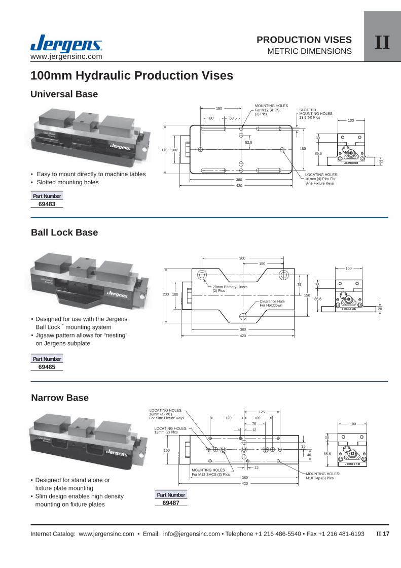
Universal Base
Ball Lock Base
Narrow Base
• Easy to mount directly to machine tables• Slotted mounting holes
• Designed for use with the Jergens Ball Lock™ mounting system
• Jigsaw pattern allows for “nesting” on Jergens subplate
• Designed for stand alone or fi xture plate mounting
• Slim design enables high density mounting on fi xture plates
Part Number69483
Part Number69485
Part Number69487
100mm Hydraulic Production Vises

IIwww.jergensinc.com
II.18
PRODUCTION VISESMETRIC DIMENSIONS
Jergens, Inc. • Jergens Way • 15700 S. Waterloo Road • Cleveland, Ohio 44110-3898 USA
Universal Base
Ball Lock Base
Narrow Base
• Easy to mount directly to machine tables• Slotted mounting holes
• Designed for use with the Jergens Ball Lock™ mounting system
• Jigsaw pattern allows for “nesting” on Jergens subplate
• Designed for stand alone or fi xture plate mounting
• Slim design enables high density mounting on fi xture plates
Part Number69484
Part Number69486
Part Number69488
150mm Hydraulic Production Vises
32
85.6
38
150
508
555
225 150
63.5100
200
216
75
200
SLOTTED MOUNTING HOLES:13.5mm (4) Plcs
LOCATING HOLES:16mm (4) Plcs ForSine Fixture Keys
MOUNTING HOLES:For M12 SHCS (6) Plcs
20
85.6
38
150
508
555
100
200
150
300
150250
(2) Plcs
Clearance HoleFor Holddown
20mm Primary Liners
85.6
38
150
508
555
50100
75
125
200
28
28
150
150
LOCATING HOLES:16mm (4) PlcsFor Sine Fixture Keys
MOUNTING HOLES:M10 Tap (6) Plcs
LOCATING HOLES:12mm (2) Plcs
MOUNTING HOLES: For M12 SHCS (4) Plcs

IIwww.jergensinc.com
II.19
PRODUCTION VISES METRIC DIMENSIONS
Internet Catalog: www.jergensinc.com • Email: [email protected] • Telephone +1 216 486-5540 • Fax +1 216 481-6193
Jergens Hydraulic Vises incorporate a unique, compact internal operating system. It is recommended that Jergens Power Sources be utilized. However, they will operate from machine sources or most hydraulic power sources. Jergens Booster Kit provides a completed power source for hydraulic vises in a compact package. The kit consists of a Jergens 30:1 pre-fi ll self-bleeding booster with fi lter regulator, 4 way push button actuation valve, plumbed with all fi ttings and hoses.
• Self Bleeding• Easy View Reservoir• 30:1 Boost Ratios
Kit (PN.61725) Includes• Jergens Pre-Fill Booster 61705 (30:1)• Filter Regulator• Actuator Valve
The pre-fi ll booster is ideal for use with Jergens Hydraulic vises and provide maximum effi ciency with minimum effort! Pre-fi ll boosters must be used in the upright (vertical) position. All that is required is air input and output hydraulic lines to the vises. The kit is easy to install and use.
Note: Do not use more than 270 Bar input pressure on Jergens Vises
Patent No. 3839866
Pre-Fill Boosters Kit
Specifi cationsPart Number 61705ReservoirCapacity (Litre) 0.8
High PressureVolume (cm3) 61
MinimumInput (bars) 2.7
MaximumInput (bars) 8.6
Boost Ratio 30:1MaximumOutput (bars) 258.5
Weight (kgs) 13
Part Number61725
Handle
• Ergonomic design• Machined aluminum• Special hex head for Jergens Hydraulic Vise
Part No.
49445
100mm Hydraulic Vise Handle
Part No.
49465
150mm Hydraulic Vise Handle
Pre-Fill Booster only

IIwww.jergensinc.com
II.20
PRODUCTION VISESMETRIC DIMENSIONS
Jergens, Inc. • Jergens Way • 15700 S. Waterloo Road • Cleveland, Ohio 44110-3898 USA
B
A
C D
E
Soft Jaws
B
A
C D F
G
E
Hard Jaws
Production Vise Jaws
Jaws for 100mm Production Vises
Jaws for 150mm Production Vises
Part No. Description A B C D E (1) F G
49420 Standard Machinable Soft Jaw Set (3pcs.) 100 30 100 63.5 56 49421 Pair of Std Moveable Jaws Only (2pcs.) 100 30 100 49422 Std Fixed Jaw Only (1pc.) 100 30 63.5 49423 Extra Wide Machinable Soft Jaw Set (3pcs.) 150 30 100 63.5 56 49424 Pair of Wide Moveable Jaws Only (2pcs.) 150 30 100 49425 Wide Fixed Jaw Only (1pc.) 150 30 63.5 49450 Extra Tall Machinable Soft Jaw Set (3pcs.) 100 50 130 63.5 46 49451 Pair of Tall Moveable Jaws Only (2pcs.) 100 50 130 49452 Tall Fixed Jaw Only (1pc.) 100 50 63.5 49426 Hard Jaw Carrier Set (2) (3pcs.) 100 30 88 24 73 49428 Pair of Moveable Hard Jaws Only (2pcs.) 100 30 88 49427 Fixed Hard Jaw Only (1pc.) 100 30 24 49429 Hardened Steel Jaw Insert Set(3) (4pcs.) 100 10 30
(2) Steel Inserts NOT included (1) Mounted Dimensions
(3) Steel inserts have black-oxide fi nish, and are hardened to Rc 54/58.
Part No. Description A B C D E (1) F G
49430 Standard Machinable Soft Jaw Set (3pcs.) 150 38 130 78 88 49431 Pair of Std Moveable Jaws Only (2pcs.) 150 38 130 49432 Std Fixed Jaw Only (1pc.) 150 38 78 49433 Extra Wide Machinable Soft Jaw Set (3pcs.) 200 38 130 78 88 49434 Pair of Wide Moveable Jaws Only (2pcs.) 200 38 130 49435 Wide Fixed Jaw Only (1pc.) 200 38 78 49455 Extra Tall Machinable Soft Jaw Set (3pcs.) 150 63 150 78 75 49453 Pair of Tall Moveable Jaws Only (2pcs.) 150 63 150 49454 Tall Fixed Jaw Only (1pc.) 150 63 78 49436 Hard Jaw Carrier Set (2) (3pcs.) 150 38 115 24 100 49438 Pair of Moveable Hard Jaws Only (2pcs.) 150 38 115 49437 Fixed Hard Jaw Only (1pc.) 150 38 24 49439 Hardened Steel Jaw Insert Set (3) (4pcs.) 150 12 38
(2) Steel Inserts NOT included (1) Mounted Dimensions
(3) Steel inserts have black-oxide fi nish, and are hardened to Rc 54/58.

IIwww.jergensinc.com
II.21
PRODUCTION VISES METRIC DIMENSIONS
Internet Catalog: www.jergensinc.com • Email: [email protected] • Telephone +1 216 486-5540 • Fax +1 216 481-6193
Full Face Vise Plate
Production Vise Accessories Jaws & Fixture PlatesJaws• Standard fully machinable soft jaws, as supplied on
the Production Vises and Columns• Extra Wide fully machinable soft jaws.• Extra High fully machinable soft jaws.• Hard Jaw Carriers are hard anodized aluminum jaws;
drilled and tapped to accept hard jaw inserts. • Hard Jaw Inserts are hardened steel plates that bolt
onto the hard jaw carriers.
Jaws are offered three ways:• Jaw Sets include two moveable jaws and one fi xed jaw.• Moveable Jaws are sold in pairs• Fixed Jaws are sold each.
Full Face Vise Plates Vise plates provide an alternative to holding parts in the jaws of Jergens Production Vises. Build dedicated fi xtures on the plates, and then just snap them onto a Vise or Column. Use a combination of vise plates and jaws to machine related parts in the same set-up. Switch between fi xtures and jaws, without removing the Vise or Column from the machine.
M8 X 1.25 Tap, 10mm Deep(2) Plcs
E
D
B A
C
NOTE: Conversion plates include mounting screws.
• Allows for easy conversion from twin station to single station vise
• Hard coat anodized aluminum
• Ergonomic Design• Machined Aluminum• 5/8” Hex Size
Vise Conversion Plates Vise Handles Vise Work Stop
Jergens offers a variety workholding options for our Production Vises.
Hard Jaw Carriers With Steel Inserts(Steel Inserts Ordered Seperately)
Conversion Plate
Work Stop
Handle - For Manual Vises
Part No. Vise Size
49440 100mm 49441 150mm
Part No. Vise Size
49442 100mm 49443 150mm • Easily mounts to
side of twin vise• Allows for precise
part location
Part No.
49444
Machineable Soft Jaws (Standard)
Full Face Vise Plates for 100mm Production Vises
Part No. Description A B C D E 49446 Standard Vise Plate 100 380 37 6 12 49448 Wide Vise Plate 150 380 37 6 12
Full Face Vise Plates for 150mm Production VisesPart No. Description A B C D E 49447 Standard Vise Plate 150 508 37 6 17 49449 Wide Vise Plate 200 508 37 6 17

IIwww.jergensinc.com
II.22
PRODUCTION VISESMETRIC DIMENSIONS
Jergens, Inc. • Jergens Way • 15700 S. Waterloo Road • Cleveland, Ohio 44110-3898 USA
www.jergensinc.com
Ball Lock™ Accessories for Jergens Production Vises
Primary Liners(2) Plcs
Clearance holes for holddown (2) Plcs
16mm Bored hole for sine fi xture key(2) Plcs
Ball Lock Sub-Plates for Ball Lock Vises, Columns, and Fixture Plates
*Fits Jergens Tooling Column 69011
Ball Lock Fixture Plates for Multiple Production Vises
300
150200
400
200
250
CLEARANCE HOLE FORHOLDDOWN
(2) 20MMPRIMARY LINERSINSTALLED
Jigsaw Interlocking Fixture Plates
Jergens manufactures standard Ball Lock Fixture Plates for various applications. A small sample is listed below. These fi xture plates will accept multiple Jergens Production Vises. However, the Jergens Ball Lock Mounting System can provide the greatest benefi ts, when designed for your specifi c applications and your machine tools. Please contact Jergens Technical Service to select the proper fi xture and sub-plate for your applications.
Jergens manufactures standard sub-plates for popular machine tools. Three standard plates are shown. These sub-plates will accept Jergens Ball Lock Vises, Columns and Fixture Plates. Some of the sub-plates have multiple mounting patterns that will allow multiple sizes and styles
Ball Lock Shanks Shank Shank Fixture/Base Standard with Diameter Thickness Shank Thumbscrew 20 20 49651 49651-S
20 25 49652 49652-S 25 20 49661 49661-S 25 25 49662 49662-S Standard
ShankThumb Screw
Jigsaw Fixture Plate
Multiple Vise Fixture Plate
of fi xture plates and vises to be used on the same machine. However, the Jergens Ball Lock Mounting System can provide the greatest benefi ts, when designed for your specifi c applications and your machine tools. Please contact Jergens Technical Service to select the proper sub-plate for your machine.
Plate Machine Table Ball Lock Part No. Type Size Pattern Applications 59102 HMC 400mm 350x350 Vise Columns, Tooling Columns, Other 59103-C HMC 500mm 425x425 & 350x350 Vise Columns, Tooling Columns, Other 59112 VMC 500x1000 Multiple Patterns Jigsaw Vises & Plates, Multiple Vise Fixtures, Other
Plate Ball Lock Shank Plate Outer Vises/ Use With Wt. Part No. Pattern Diameter Thickness Dimensions Plate Vise No. (kgs) 58713 300 x 300 20mm 20 350 x 350 2 69401 6 58715 300 x 300 20mm 20 400 x 400 2 69401 8 58727 425 x 425 25mm 25 500 x 500 3 69401 17 58727 425 x 425 25mm 25 500 x 500 2 69402 17 *58742 175 x 550 25mm 25 300 x 625 2 69401 13
Plate Jig Saw Plate Outer Use With Wt. Part No. Pattern Thickness Dimensions Vise No. (kgs) 58706 200 x 300 20 250 x 400 69402 4

IIIwww.jergensinc.com
III.1
LOCATING & CLAMPING COMPONENTSMETRIC DIMENSIONS
Internet Catalog: www.jergensinc.com • Email: [email protected] • Telephone +1 216 486-5540 • Fax +1 216 481-6193
III Locating & Clamping
Locating DevicesPull Dowels ....................................... III.2Precision Expanding Dowels ............ III.2Construction Ball .............................. III.3Rest Buttons ..................................III.3-4Rest Pad ........................................... III.4Jig Feet ............................................. III.5Flat Feet ........................................... III.5Standard Fixture Keys ...................... III.5Sine Fixture Keys ............................. III.6
Spring Loaded DevicesRetractable Plungers ........................ III.6Spring Stops ..................................... III.7Spring Plungers ................................ III.8Shortie Spring Plungers.................... III.9Ball Plungers .................................... III.9Special Plungers request................ III.10
The benefi ts of Jergens Plungers ... III.11
Threaded InsertsInstalltation Information .................. III.12Master Thread Repair Kits .............. III.12Keylocking Inserts .......................... III.13
Workholding ComponentsTru-Center™ Toggle Products Toggle Pads ............................ III.14 Leveling Pads ......................... III.14 Threaded ................................ III.15Adjustable Clamp Heels ................. III.15Quarter Turn Screws ...................... III.16Thumb Screws................................ III.16Studs .............................................. III.17Flange Nuts ................................... III.18Spherical Flange Assemblies ......... III.18Spherical Flange Nuts .................... III.18Spinner-Grip™ Flange Lock Nuts... III.19T-Slot Nuts ...................................... III.19Coupling Nuts ................................. III.19Heavy Duty Flat Washers ............... III.20Self Aligning Washers ..................... III.20ID Expansion Clamp ....................... III.21Expanding Micro™ Clamps ............ III.22 Machinable ............................ III.23Adjustable Micro™ Clamps ............ III.24Micro™ Clamps .............................. III.25Knife Edge Clamps ......................... III.25Lo-Profi le Micro™ Clamps.............. III.26Micro™ Toe Clamps ....................... III.27Micro™ T-Slot Toe Clamps ............. III.27Micro™ Edge Clamps..................... III.28

IIIwww.jergensinc.com
III.2
LOCATING & CLAMPING COMPONENTSMETRIC DIMENSIONS
Jergens, Inc. • Jergens Way • 15700 S. Waterloo Road • Cleveland, Ohio 44110-3898 USA
Part Number A L T 31751 8 20 M5 x 0.8 31753 8 30 M5 x 0.8 31755 8 40 M5 x 0.8 31759 10 20 M6 x 1.0 31761 10 30 M6 x 1.0 31763 10 40 M6 x 1.0 31765 10 50 M6 x 1.0 31767 10 70 M6 x 1.0 31769 12 20 M6 x 1.0 31771 12 30 M6 x 1.0 31773 12 40 M6 x 1.0
Part Number A L T 31775 12 50 M6 x 1.0 31776 12 60 M6 x 1.0 31777 12 70 M6 x 1.0 31780 16 40 M8 x 1.25 31782 16 50 M8 x 1.25 31783 16 60 M8 x 1.25 31784 16 70 M8 x 1.25 31787 20 50 M10 x 1.5 31788 20 60 M10 x 1.5 31789 20 70 M10 x 1.5
• Material: Low Carbon Steel• Heat Treat: Case Hardened• Available in FixtureProTM
Design Software
Flat ground on the side for air release in blind holes.
Pull Dowels
Button head screw not included.
Precision Expanding Dowels• Material: Steel, hardened to 50-55 Rockwell C• Self-Centering and Repeatable to within +/- 0.013mm• Top and bottom half of dowel expand seperately• Patented
H
D
Installation Instructions
Step 1Remove the top screw, insert the dowel into the locating hole of the fi rst part, and expand the bottom half with a hex wrench.
Step 2Replace the top screw, slide the locating hole of the second part over the dowel and expand top half with a hex wrench.
Part Number Diameter Height Hex Size
29451 10 20 4 29452 12 24 5 29453 14 28 5 29454 16 32 6 29455 20 40 8

IIIwww.jergensinc.com
III.3
LOCATING & CLAMPING COMPONENTSMETRIC DIMENSIONS
Internet Catalog: www.jergensinc.com • Email: [email protected] • Telephone +1 216 486-5540 • Fax +1 216 481-6193
“B” Ground† “B” Unground† Part Part Number Number A B C D 34751 45771 10 6 12 5 34754 45774 13 6 18 6 34757 45777 16 6 18 10 34758 45778 16 10 22 10 34759 45780 16 12 25 10 34763 45786 22 16 31 12 34766 45790 25 12 30 16
†“B” Dimension for ground style is +0.013/-0.000mm, ungrounded style is +0.25/+0.38mm.
Jergens is proud of the close tolerances held on the "B" dimension of our Ground Rest Buttons. When it becomes necessary through constant wear to replace rest buttons, they can be replaced with the assurance of being within 0.013mm of the original location. Where replacement is not going to be a problem, we recommend the use of the Unground Buttons, which have a 0.25mm grinding stock to be ground after the fi xture is assembled.
• Material: Ground, Low Carbon Steel Unground, 52100• Finish: Black Oxide • Heat Treat: Ground, Case Hardened 75-77 R30N Unground, 58-62 Rc• Available in FixtureProTM Design Software
Rest ButtonsGround and Unground The Closest Tolerances in the Industry...
Part Number A B C D E 34951 13 6 18 6 10 34953 16 10 22 10 10 34955 25 12 30 16 19
Carbide Insert Rest Buttons
• Material: Body, Low Carbon Steel Insert, Carbide• Available in FixtureProTM Design Software
• One Piece Construction• Close Tolerances—0.005mm T.I.R.• 8620 Steel Hardened Rc58-62• Available in FixtureProTM Design Software
Construction Ball
± +0.000/- ± Net Part 0.005mm 0.010mm 0.005mm Dia. Wt. Number A B C D E 10 Pcs 29090 6mm 3mm 6mm 16mm 6mm 0.1 29091 10mm 5mm 10mm 20mm 10mm 0.3 29092 12mm 6mm 12mm 22mm 12mm 0.3

IIIwww.jergensinc.com
III.4
LOCATING & CLAMPING COMPONENTSMETRIC DIMENSIONS
Jergens, Inc. • Jergens Way • 15700 S. Waterloo Road • Cleveland, Ohio 44110-3898 USA
Part Number A B C E F G H 35951 25 25 50 12 10 13 M5 38 35952 25 38 64 15 13 13 M6 50 35954 25 50 89 18 16 19 M8 70
• Material: Low Carbon Steel• Finish: Black Oxide• Heat Treat: Case Hardened 75-77 R30N• Available in FixtureProTM Design Software
Rest Pad Rest Pads are designed to be used when you need a larger hardened wearing surface for heavy duty applications. Rest Pads can also be used as hardened work rests or as wear plates on your jigs and fi xtures.
+0.013 -0.000
D
Part Number A B C E F G H I J 35953 50 50 75 18 12 13 M6 64 13 25
+0.013 -0.000
D
Jergens Feature:By holding close tolerances on the “D” dimension, when replacement becomes necessary, your original tolerances are maintained within 0.013mm
+.013- .000
• Material: Low Carbon Steel• Finish: Black Oxide• Heat Treat: Case Hardened 75-77 R30N• Available in FixtureProTM Design Software
Rest Pads are designed to be used when you need a larger hardened wearing surface for heavy duty applications. Rest Pads can also be used as hardened work rests or as wear plates on your jigs and fi xtures.
Rest Pad
Across Part Dia. Flats Number A B C†
D
E 21551 10 6 14 M6x1.0 8 21554 13 6 17 M10x1.5 10 21558 16 10 25 M12x1.75 14 21561 25 12 30 M16x2.0 20
† +0.25/+0.38 mm Grinding Stock
Thread into job instead of press fi t. “B” dimensionleft with 0.25mm-0.38mm for fi nishing after assembly. For cutter setting blocks on milling fi xtures, grind to your own specifi cations. Case hardened to approximately 0.76mm deep.
Threaded Rest Buttons
• Material: Low Carbon Steel• Finish: Black Oxide• Heat Treat: Case Hardened 75-77 R30N• Thread: Class 6g
+.013- .000
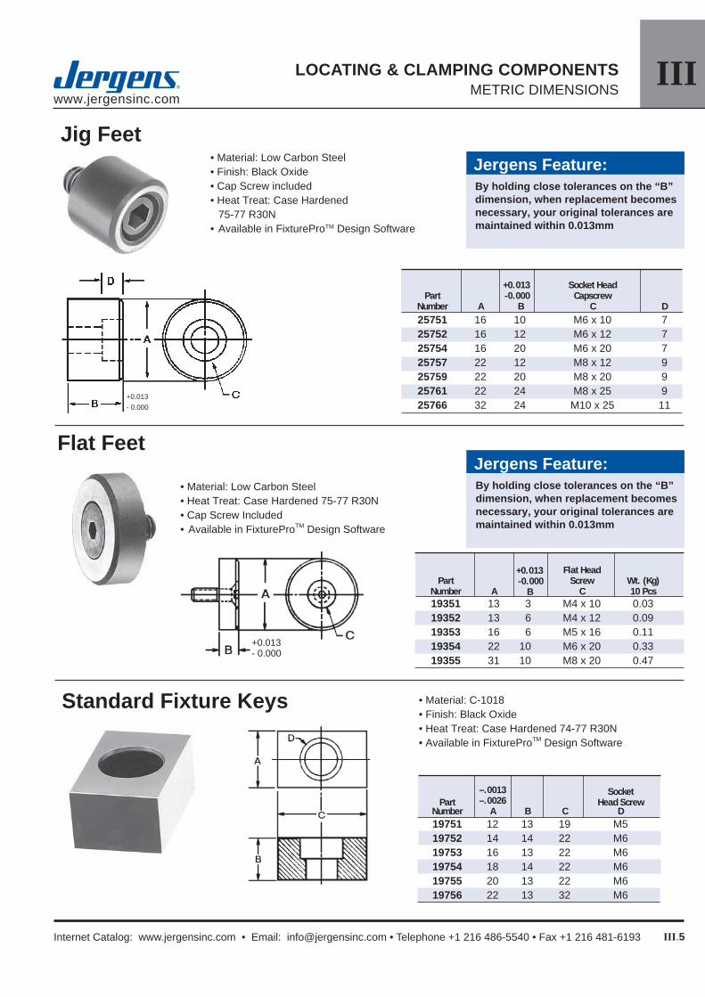
IIIwww.jergensinc.com
III.5
LOCATING & CLAMPING COMPONENTSMETRIC DIMENSIONS
Internet Catalog: www.jergensinc.com • Email: [email protected] • Telephone +1 216 486-5540 • Fax +1 216 481-6193
• Material: Low Carbon Steel• Finish: Black Oxide• Cap Screw included• Heat Treat: Case Hardened
75-77 R30N• Available in FixtureProTM Design Software
Jig Feet
+0.013 Socket Head Part -0.000 Capscrew Number A B C D 25751 16 10 M6 x 10 7 25752 16 12 M6 x 12 7 25754 16 20 M6 x 20 7 25757 22 12 M8 x 12 9 25759 22 20 M8 x 20 9 25761 22 24 M8 x 25 9 25766 32 24 M10 x 25 11
Jergens Feature:By holding close tolerances on the “B” dimension, when replacement becomes necessary, your original tolerances are maintained within 0.013mm
• Material: Low Carbon Steel• Heat Treat: Case Hardened 75-77 R30N• Cap Screw Included• Available in FixtureProTM Design Software
Flat Feet
+0.013 -0.000
B
Jergens Feature:By holding close tolerances on the “B” dimension, when replacement becomes necessary, your original tolerances are maintained within 0.013mm
Flat Head Part Screw Wt. (Kg) Number A C 10 Pcs 19351 13 3 M4 x 10 0.03 19352 13 6 M4 x 12 0.09 19353 16 6 M5 x 16 0.11 19354 22 10 M6 x 20 0.33 19355 31 10 M8 x 20 0.47
Standard Fixture Keys • Material: C-1018• Finish: Black Oxide• Heat Treat: Case Hardened 74-77 R30N• Available in FixtureProTM Design Software
–.0013 Socket Part –.0026 Head Screw Number A B C D 19751 12 13 19 M5 19752 14 14 22 M6 19753 16 13 22 M6 19754 18 14 22 M6 19755 20 13 22 M6 19756 22 13 32 M6
+0.013- 0.000
+0.013- 0.000

IIIwww.jergensinc.com
III.6
LOCATING & CLAMPING COMPONENTSMETRIC DIMENSIONS
Jergens, Inc. • Jergens Way • 15700 S. Waterloo Road • Cleveland, Ohio 44110-3898 USA
Sine Fixture Keys locate jigs and fi xtures on machine tool tables and position the part in one operation. They eliminate the need to slot fi xture bases, make step fi xture keys, or drill and tap keys. Simply ream two holes, depending upon the shank size shown in the table below.The unique expansion shaft allows the key to be locked in the fi xture from either the top or the bottom using a standard hex wrench.
Sine Fixture Keys • Material: 4140• Heat Treat: 26-30• Available in FixtureProTM Design Software• Reduce fi xture costs• Cut extra set-up time• Completely interchangeable• Fits many table slot sizes
Shank Slot Part Size Size Wt. Number A B C (kg) 39551 16 12 25 0.04 39552 16 14 25 0.05 39553 16 16 25 0.05 39554 16 18 29 0.05 39555 16 20 29 0.06 39556 16 22 29 0.06 39557 20 24 35 0.07 39558 20 28 35 0.10 39559 20 32 40 0.10
Jergens Feature:Full 360° contact for more accurate locating.
RecommendedHole Diameter
16mm Shank Size:16.01 ± 0.01
20mm Shank Size:20.01 ± 0.01
Retractable PlungersHand Retractable Locking Style • Improved design allows plunger pin to be
locked in fully retracted position• Used in machining applications as positioners,
loading pins or indexing devices• Plunger pin has slight taper on end to assure
easy alignment• Material: Zinc Plated Carbon Steel (or 303 Stainless Steel on request)• Phenolic Nose Prevents Marring of Soft Material• Supplied with locking element
Steel Class 6g +0.025Part
End Force Kilograms ISO -0.050 Net Wt. (Kg)
Number Start Full A B C D E F 10 Pcs.
27551 0.45 2.27 M6x1.0 12.50 3.17 3 6.3 12.7 0.1627552 0.68 2.72 M8x1.25 16.00 4.75 4 7.0 15.8 0.2727553 0.68 3.63 M10x1.5 19.00 5.50 5 7.9 19.0 0.3827554 1.13 4.54 M12x1.75 22.00 6.35 6 9.4 25.4 0.7
Heavy Force Hand Retractable Locking Style Plungers
Light Force Hand Retractable Locking Style PlungersSteel Class 6g +0.025Part
End Force Kilograms ISO -0.050 Net Wt. (Kg)
Number Start Full A B C D E F 10 Pcs.
27555 0.225 1.135 M6x1.0 12.50 3.17 3 6.3 12.7 0.16 27556 0.34 1.36 M8x1.25 16.00 4.75 4 7.0 15.8 0.27 27557 0.34 1.815 M10x1.5 19.00 5.50 5 7.9 19.0 0.38 27558 0.565 2.27 M12x1.75 22.00 6.35 6 9.4 25.4 0.7

IIIwww.jergensinc.com
III.7
LOCATING & CLAMPING COMPONENTSMETRIC DIMENSIONS
Internet Catalog: www.jergensinc.com • Email: [email protected] • Telephone +1 216 486-5540 • Fax +1 216 481-6193
Spring StopsButton Type
Tang TypeFlat Button Type
Jergens Features:Set screw allows for adjustable plunger travel.
Angled mounting slot provides a more secure hold.
End Force (Half-Depressed)36101, 36104, 36107 – 4.5 kg36102, 36105, 36111 – 6.4 kg36103, 36106, 36109 – 14.5 kg
• Material: Body, Zinc Aluminum Alloy ZA-12 Plunger, Low Carbon Steel
• Heat Treat: Plunger Case Hardened 74-77 R30N
Bu
tto
nT
ang
Fla
t
Dimensions (mm)
Part. Stroke Wt. (kg.) No. A B C D E F G H I J K L M N O P 10 Pcs. 36101 23.8 17.5 16.7 3.6 8.9 15.1 9.5 3.2 5.6 5.6 10.3 – – – – – 0.09
36102 38.1 25.4 28.6 5.1 13.7 21.4 14.3 4.8 7.9 7.1 15.9 – – – – – 0.41
36103 50.8 34.9 38.1 6.5 17.5 31 20.6 6.4 11.1 7.9 22.2 – – – – – 0.84
36104 23.8 17.5 16.7 3.6 8.9 15.1 15.9 3.2 5.6 5.6 10.3 4.8 22.2 6.4 11.1 6 0.09
36105 38.1 25.4 28.6 5.1 13.7 21.4 22.2 4.8 7.9 7.1 15.9 6.4 28.6 9.5 14.3 6.7 0.41
36106 50.8 34.9 38.1 6.5 17.5 31 31.8 6.4 11.1 7.9 22.2 9.5 38.1 12.7 19.1 8.3 0.84
36107 23.8 17.5 16.7 3.6 8.9 15.1 19.1 3.2 5.6 5.6 10.3 4.8 22.2 0.4 – – 0.09
36111 38.1 25.4 28.6 5.1 13.7 21.4 22.2 4.8 7.9 7.1 15.9 6.4 28.6 0.4 – – 0.41
36109 50.8 34.9 38.1 6.5 17.5 31 38.1 6.4 11.1 7.9 22.2 9.5 38.1 0.4 – – 0.84
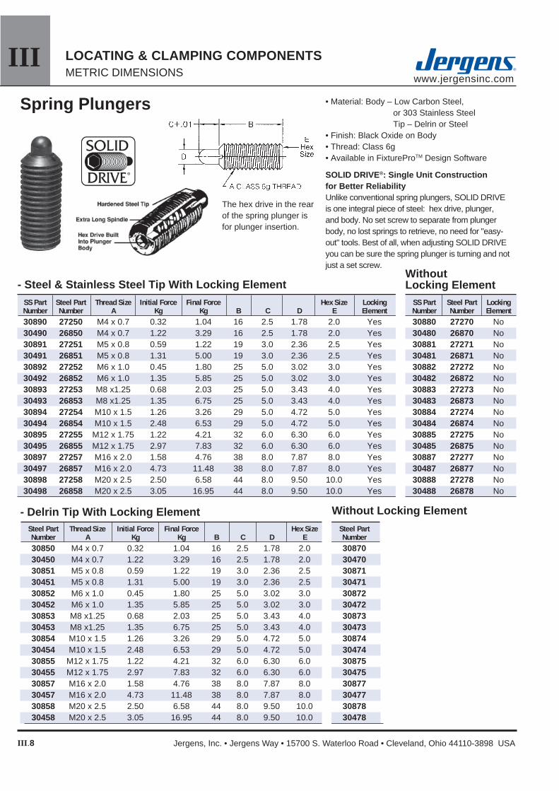
IIIwww.jergensinc.com
III.8
LOCATING & CLAMPING COMPONENTSMETRIC DIMENSIONS
Jergens, Inc. • Jergens Way • 15700 S. Waterloo Road • Cleveland, Ohio 44110-3898 USA
Spring Plungers • Material: Body – Low Carbon Steel, or 303 Stainless Steel Tip – Delrin or Steel• Finish: Black Oxide on Body• Thread: Class 6g• Available in FixtureProTM Design Software
SOLID DRIVE®: Single Unit Construction for Better ReliabilityUnlike conventional spring plungers, SOLID DRIVE is one integral piece of steel: hex drive, plunger, and body. No set screw to separate from plunger body, no lost springs to retrieve, no need for "easy-out" tools. Best of all, when adjusting SOLID DRIVE you can be sure the spring plunger is turning and not just a set screw.
The hex drive in the rear of the spring plunger is for plunger insertion.
- Steel & Stainless Steel Tip With Locking Element SS Part Steel Part Thread Size Initial Force Final Force Hex Size Locking SS Part Steel Part Locking Number Number A Kg Kg B C D E Element Number Number Element 30890 27250 M4 x 0.7 0.32 1.04 16 2.5 1.78 2.0 Yes 30880 27270 No 30490 26850 M4 x 0.7 1.22 3.29 16 2.5 1.78 2.0 Yes 30480 26870 No 30891 27251 M5 x 0.8 0.59 1.22 19 3.0 2.36 2.5 Yes 30881 27271 No 30491 26851 M5 x 0.8 1.31 5.00 19 3.0 2.36 2.5 Yes 30481 26871 No 30892 27252 M6 x 1.0 0.45 1.80 25 5.0 3.02 3.0 Yes 30882 27272 No 30492 26852 M6 x 1.0 1.35 5.85 25 5.0 3.02 3.0 Yes 30482 26872 No 30893 27253 M8 x1.25 0.68 2.03 25 5.0 3.43 4.0 Yes 30883 27273 No 30493 26853 M8 x1.25 1.35 6.75 25 5.0 3.43 4.0 Yes 30483 26873 No 30894 27254 M10 x 1.5 1.26 3.26 29 5.0 4.72 5.0 Yes 30884 27274 No 30494 26854 M10 x 1.5 2.48 6.53 29 5.0 4.72 5.0 Yes 30484 26874 No 30895 27255 M12 x 1.75 1.22 4.21 32 6.0 6.30 6.0 Yes 30885 27275 No 30495 26855 M12 x 1.75 2.97 7.83 32 6.0 6.30 6.0 Yes 30485 26875 No 30897 27257 M16 x 2.0 1.58 4.76 38 8.0 7.87 8.0 Yes 30887 27277 No 30497 26857 M16 x 2.0 4.73 11.48 38 8.0 7.87 8.0 Yes 30487 26877 No 30898 27258 M20 x 2.5 2.50 6.58 44 8.0 9.50 10.0 Yes 30888 27278 No 30498 26858 M20 x 2.5 3.05 16.95 44 8.0 9.50 10.0 Yes 30488 26878 No
Steel Part Thread Size Initial Force Final Force Hex Size Steel Part Number A Kg Kg B C D E Number 30850 M4 x 0.7 0.32 1.04 16 2.5 1.78 2.0 30870 30450 M4 x 0.7 1.22 3.29 16 2.5 1.78 2.0 30470 30851 M5 x 0.8 0.59 1.22 19 3.0 2.36 2.5 30871 30451 M5 x 0.8 1.31 5.00 19 3.0 2.36 2.5 30471 30852 M6 x 1.0 0.45 1.80 25 5.0 3.02 3.0 30872 30452 M6 x 1.0 1.35 5.85 25 5.0 3.02 3.0 30472 30853 M8 x1.25 0.68 2.03 25 5.0 3.43 4.0 30873 30453 M8 x1.25 1.35 6.75 25 5.0 3.43 4.0 30473 30854 M10 x 1.5 1.26 3.26 29 5.0 4.72 5.0 30874 30454 M10 x 1.5 2.48 6.53 29 5.0 4.72 5.0 30474 30855 M12 x 1.75 1.22 4.21 32 6.0 6.30 6.0 30875 30455 M12 x 1.75 2.97 7.83 32 6.0 6.30 6.0 30475 30857 M16 x 2.0 1.58 4.76 38 8.0 7.87 8.0 30877 30457 M16 x 2.0 4.73 11.48 38 8.0 7.87 8.0 30477 30858 M20 x 2.5 2.50 6.58 44 8.0 9.50 10.0 30878 30458 M20 x 2.5 3.05 16.95 44 8.0 9.50 10.0 30478
- Delrin Tip With Locking Element
Without Locking Element
Without Locking Element

IIIwww.jergensinc.com
III.9
LOCATING & CLAMPING COMPONENTSMETRIC DIMENSIONS
Internet Catalog: www.jergensinc.com • Email: [email protected] • Telephone +1 216 486-5540 • Fax +1 216 481-6193
Shortie Spring PlungersJergens Feature:Jergens Shortie Spring Plungers are made to the same quality standards as the Solid Drive® *Made with full standard spring plunger stroke in a short body. A screwdriver slot is substituted for the hex drive due to the smaller size.*Carbon Steel body only
• Material: Body – Low Carbon Steel, or 303 Stainless Steel on request Tip – Delrin or Steel• Finish: Black Oxide on Body • Thread: Class 6g• Available in FixtureProTM Design SoftwarePlunger Tips are color coded to indicate light or heavy force.White = Light Force Blue = Heavy Force
Thread Size Initial Force Final Force Steel Tip Delrin Tip A (kg) (kg) B C D 27170 30770 M4 x 0.7 0.23 0.91 13.0 2.5 1.78 26770 30370 M4 x 0.7 0.23 1.81 13.0 2.5 1.78 27171 30771 M5 x 0.8 0.14 1.36 14.5 3.0 2.36 26771 30371 M5 x 0.8 0.23 2.27 14.5 3.0 2.36 27172 30772 M6 x 1.0 0.14 1.59 16.0 4.0 3.02 26772 30372 M6 x 1.0 0.23 2.72 16.0 4.0 3.02 27173 30773 M8 x 1.25 0.23 2.04 16.0 5.0 3.43 26773 30373 M8 x 1.25 0.23 4.54 16.0 5.0 3.43 27174 30774 M10 x 1.5 0.68 3.4 17.5 5.5 4.72 26774 30374 M10 x 1.5 0.46 5.44 17.5 5.5 4.72 27175 30775 M12 x 1.75 0.77 3.86 20.5 6.5 6.30 26775 30375 M12 x 1.75 1.13 6.80 20.5 6.5 6.30 27177 30777 M16 x 2.0 0.91 4.76 28.5 8.0 7.87 26777 30377 M16 x 2.0 1.59 11.79 28.5 8.0 7.87
IMPORTANT: When inserting Ball Plungers with nylon locking elements, the tapped hole should be countersunk at least 0.76mm to 1.14mm larger than the major diameter of the plunger. This will make insertion of the plunger easier.
• Body Material: Low Carbon Steel or 303 Stainless Steel• Ball Material: Stainless, 440• Spring Material: Stainless, 17-7 PH• Finish: Black Oxide on Body• Thread: Class 6g• Available in FixtureProTM Design Software
Ball Plungers
Steel & SS Tip With Locking Element Without Locking Element SS Part Steel Part Thread Size Initial Force Final Force SS Part Steel Part Number Number A Kg Kg B C D Number Number 11051 10971 M4 x 0.7 0.23 0.56 9.00 0.60 2.38 10951 10871 11052 10972 M5 x 0.8 0.23 0.68 13.00 0.60 2.38 10952 10872 11053 10973 M5 x 0.8 0.68 1.35 13.00 0.60 2.38 10953 10873 11054 10974 M5 x 0.8 0.90 2.25 13.00 0.60 2.38 10954 10874 11055 10975 M6 x 1.0 0.90 1.80 13.50 0.90 3.18 10955 10875 11056 10976 M6 x 1.0 1.35 3.15 13.50 0.90 3.18 10956 10876 11057 10977 M6 x 1.0 1.80 5.40 13.50 0.90 3.18 10957 10877 11058 10978 M8 x1.25 0.90 2.03 15.00 1.00 3.97 10958 10878 11059 10979 M8 x1.25 1.80 4.05 15.00 1.00 3.97 10959 10879 11060 10980 M8 x1.25 2.70 7.65 15.00 1.00 3.97 10960 10880 11061 10981 M10 x 1.5 1.13 2.25 16.00 1.20 4.76 10961 10881 11062 10982 M10 x 1.5 2.25 4.50 16.00 1.20 4.76 10962 10882 11063 10983 M10 x 1.5 2.70 9.45 16.00 1.20 4.76 10963 10883 11064 10984 M12 x 1.75 1.35 2.70 19.00 2.00 7.14 10964 10884 11065 10985 M12 x 1.75 2.70 5.40 19.00 2.00 7.14 10965 10885 11066 10986 M12 x 1.75 2.70 13.50 19.00 2.00 7.14 10966 10886 11067 10987 M16 x 2.0 2.00 4.00 25.40 2.40 9.50 10967 10887 11068 10988 M16 x 2.0 4.00 8.10 25.40 2.40 9.50 10968 10888 11069 10989 M16 x 2.0 3.10 22.70 25.40 2.40 9.50 10969 10889

IIIwww.jergensinc.com
III.10
LOCATING & CLAMPING COMPONENTSMETRIC DIMENSIONS
Jergens, Inc. • Jergens Way • 15700 S. Waterloo Road • Cleveland, Ohio 44110-3898 USA
Special Spring and Ball PlungersIf you don’t see the exact spring or ball plunger to meet your application requirements, photocopy the form below, indicate your requirements, and mail to your Jergens Distributor.
A dim. (See note below) C dim.B dim. D dim.
SHORTIE
BALL
SPRING
PLUNGER QUOTATION REQUEST WORKSHEET
Application (describe):
Type of Plunger: Solid Drive® Spring “Shortie” Ball Other (see sketch)
Thread or O.D. (Class 6g Threads unless Otherwise Specifi ed)
Length of Plunger Travel:
Initial Force Required: Final Force Required:
Plastic Locking Patch: Required Not Required Tip/Ball Material:
Tip/Ball Finish: Body Material:
Body Finish: Spring Material:
Temperature Range:
Type of Environment (describe—corrosives, chemicals, contaminants, etc.):
Other Specifi cations:
Quantity Needed: Delivery By:
NAME: TITLE:
COMPANY: ADDRESS:
CITY: STATE: ZIP:
TELEPHONE: FAX:

IIIwww.jergensinc.com
III.11
LOCATING & CLAMPING COMPONENTSMETRIC DIMENSIONS
Internet Catalog: www.jergensinc.com • Email: [email protected] • Telephone +1 216 486-5540 • Fax +1 216 481-6193
Spring PlungersSpring Plunger tips made by most manufac-turers are case hardened. This means they have a protective shell, about 2.5mm deep. Beneath this shallow veneer is mild, untreated steel. The Jergens plungers are fabricated from solid tool steel and hardened throughout.
Jergens Spring and Ball Plungers have ac-curate end forces, are easy to install, and are competitively priced. They are manufactured in the U.S.A. in a ISO 9001 certifi ed quality system.
And if these aren’t enough reasons to specify Jergens Spring and Ball Plungers, here are a few more:
Better Point of ContactThe Jergens plungers are turned and the tips generated in one smooth continuing process. This results in a constant radius tip, perfectly tangent to the point where the tip joins the shaft. Conventional two step, turn and grind operations, can leave ridges on the shaft at the tip junction and can also produce out-of-round tips. These, in turn, can gouge or score fi nely fi nished parts or can cause detent cams to hang up or stick.
Extra Length Springs for Longer LifeThe longer the spring, the longer its life. Jergens goes to extra lengths to minimize the thickness of the base fl anges on all of its plungers. That allows us to use longer springs with less chance for fatigue and breakage.
Improved Plunger to Body AlignmentThe long base fl ange allows for a larger bearing surface. This means improved plunger-to-body alignment, truer travel, and much improved side load characteristics.
Tighter Fit Resists ContaminationCloser machining tolerances, minimum plunger-to-body clearance, and smoother plunger fi nish make Jergens plungers fi t more snugly in the plunger bore. This improves plunger alignment and provides extra resistance to contaminant entry. The results: dirt and grit cannot get to the bearing surfaces to shorten the life of the plunger.
Better Plunger AdjustmentThe Solid Drive® design assures that dur-ing removal or adjustment of the plunger, the whole plunger is moving, not just the set screw. This means no lost parts or springs falling out of the plunger.
Jergens Spring & Ball Plungers Last Longer
Ball Plungers
Positive Control of Spring PressureAccurate spring alignment is maintained by using a stainless rivet with a long shank on larger sizes of Jergens Ball Plungers. This precisely positions the spring for more accurate ball travel and provides positive control of spring pressure. Conventional fl oating discs are easily misaligned, while the rotation of the inner ball on dual-ball plungers results in less wearability on both the spring and the ball.
Longer Spring LifeBy minimizing the lining pin head thick-ness, Jergens is able to use the longest possible springs. This, of course, means less fatigue and longer spring life.
Uniform Ball ProjectionThe distance by which the ball projects from the body of the plunger must be uniform from plunger to plunger. This uniformity is maintained by precisely con-trolling the crimping pressure applied to the neck of the plunger. Accurate machine controls plus rigid inspection procedures keep variances in ball projection to within ±0.13mm.
...And Here's Why!

IIIwww.jergensinc.com
III.12
LOCATING & CLAMPING COMPONENTSMETRIC DIMENSIONS
Jergens, Inc. • Jergens Way • 15700 S. Waterloo Road • Cleveland, Ohio 44110-3898 USA
Installation Information
1. Drill to allow full tap depth. Note: Tap drill is oversized;
3. Install insert 0.25mm to 0.76mm below surface.
2. Tap to depth shown in chart.
4. Drive keys down with proper installation tool.
Removal InformationJergens Keylocking Inserts can be removed without damage to the parent material.
1. Drill the insert to the size and depth shown under removal data in the chart below.
2. Bend the keys down and break them off.
3. Remove the insert using an E-Z out or similar tool.
Threaded Insert
Master Thread Repair Kits
The Jergens Master Thread Repair Kits include several different kinds of inserts, installation tools and installation and removal instructions.
The Kits are available with carbon steel inserts or with stainless steel inserts.
Thinwall Kits-Small Assortments
Thinwall Kits-Large Assortments Internal External Quantity Thread Thread Length of Inserts Class 6H Class 6g (mm) Per Kit M 6x1.0 M 10x1.25 10.0 20 M 8x1.25 M 12x1.25 12.0 15 M 8x1.0 M 12x1.25 12.0 15 M 10x1.5 M 14x1.5 14.0 10 M 10x1.25 M 14x1.5 14.0 10 M 12x1.75 M 16x1.5 16.0 6 M 12x1.25 M 16x1.5 16.0 6 Total Inserts Per Kit 82 pcs.
Internal External Quantity Thread Thread Length of Inserts Class 6H Class 6g (mm) Per Kit M 5x0.8 M 8x1.25 8.0 8 M 6x1.0 M 10x1.25 10.0 8 M 8x1.25 M 12x1.25 12.0 6 M 8x1.0 M 12x1.25 12.0 6 M 10x1.5 M 14x1.5 14.0 4 M 10x1.25 M 14x1.5 14.0 4 M 12x1.75 M 16x1.5 16.0 3 M 12x1.25 M 16x1.5 16.0 3 Total Inserts Per Kit 42 pcs.
Carbon Steel Kit25999
Stainless Steel Kit25998
Carbon Steel Kit25997
Stainless Steel Kit25996

IIIwww.jergensinc.com
III.13
LOCATING & CLAMPING COMPONENTSMETRIC DIMENSIONS
Internet Catalog: www.jergensinc.com • Email: [email protected] • Telephone +1 216 486-5540 • Fax +1 216 481-6193
Part Number Insert Installation Removal
Internal External Length Installation Tap C’sink Thread Tap Drill Carbon Stainless Thread Thread L Tool Drill Dia.
Size Min.
Size Depth Steel Steel Class 6H Class 6g Part No. Size +.25
Class 6h Depth -.00
25951 26351 M 5x0.8 M 8x1.25 8.0 24751 6.9 8.25 M 8x1.25 9.5 5.50 4.00 25952 26352 M 6x1.0 M 10x1.25 10.0 24752 8.8 10.25 M 10x1.25 11.5 7.50 4.75 25953 26353 M 8x1.25 M 12x1.25 12.0 24753 10.8 12.25 M 12x1.25 13.5 9.50 4.75 26153 26553 M 8x1.0 M 12x1.25 12.0 24753 10.8 12.25 M 12x1.25 13.5 9.50 4.75 25955 26355 M 10x1.5 M 14x1.5 14.0 24755 12.8 14.25 M 14x1.5 15.5 11.50 4.75 26155 26555 M 10x1.25 M 14x1.5 14.0 24755 12.8 14.25 M 14x1.5 15.5 11.50 4.75 25956 26356 M 12x1.75 M 16x1.5 16.0 24756 14.75 16.25 M 16x1.5 17.5 13.50 4.75 26156 26556 M 12x1.25 M 16x1.5 16.0 24756 14.75 16.25 M 16x1.5 17.5 13.50 4.75
• Material: Carbon Steel Inserts - C1215 or equivalent Stainless Steel Insert - 303
Keys - 302• Finish: Carbon Steel Inserts - Parkerized
Stainless Steel Inserts - Passivated• Tolerances: ±0.25mm• Keys: Inserts with internal thread size of M8 or larger
are furnished with four locking keys.
Keylocking Inserts
Heavy Duty Industrial Style
Part Part Insert Installation Removal Number Number Internal External Length Installation Tap C'sink Thread Tap Drill Carbon Stainless Thread Thread L Tool Drill Diameter Size Min.
Size Depth Steel Steel Class 6H Class 6g Part No. Size +.25 -.00 Class 6h Depth 25963 26363 M 4x0.7 M 8x1.25 8.0 24763 6.9 8.25 M 8x1.25 9.5 5.50 4.00 25964 26364 M 5x0.8 M 10x1.25 10.0 24764 8.8 10.25 M 10x1.25 12.5 7.50 4.75 25965 26365 M 6x1.0 M 12x1.25 12.0 24765 10.8 12.25 M 12x1.25 14.5 9.50 4.75 25966 26366 M 8x1.25 M 14x1.5 14.0 24766 12.8 14.25 M 14x1.5 16.5 11.50 4.75 26166 26566 M 8x1.0 M 14x1.5 14.0 24766 12.8 14.25 M 14x1.5 16.5 11.50 4.75 25967 26367 M 10x1.5 M 16x1.5 16.0 24767 14.75 16.25 M 16x1.5 18.5 13.50 4.75 26167 26567 M 10x1.25 M 16x1.5 16.0 24767 14.75 16.25 M 16x1.5 18.5 13.50 4.75 25969 26369 M 12x1.75 M 18x1.5 18.0 24769 16.75 18.25 M 18x1.5 20.5 15.50 4.75 26169 26569 M 12x1.25 M 18x1.5 18.0 24769 16.75 18.25 M 18x1.5 20.5 15.50 4.75 25970 26370 M 14x2.0 M 20x1.5 20.0 24770 18.75 20.25 M 20x1.5 22.5 17.50 4.75 26170 26570 M 14x1.5 M 20x1.5 20.0 24770 18.75 20.25 M 20x1.5 22.5 17.50 4.75 25971 26371 M 16x2.0 M 22x1.5 22.0 24771 20.5 22.25 M 22x1.5 24.5 17.75 6.35 26171 26571 M 16x1.5 M 22x1.5 22.0 24771 20.5 22.25 M 22x1.5 24.5 17.75 6.35 26172 26572 M 18x1.5 M 24x1.5 24.0 24772 22.5 24.25 M 24x1.5 26.5 19.75 6.35 25973 26373 M 20x2.5 M 30x2.0 30.0 24773 28.0 30.25 M 30x2.0 34.5 25.75 6.35 26173 26573 M 20x1.5 M 30x2.0 30.0 24773 28.0 30.25 M 30x2.0 34.5 25.75 6.35 26174 26574 M 22x1.5 M 32x2.0 32.0 24774 30.0 32.25 M 32x2.0 36.5 27.75 6.35 25975 26375 M 24x3.0 M 33x2.0 33.0 24775 31.0 33.25 M 33x2.0 37.5 28.75 6.35 26175 26575 M 24x2.0 M 33x2.0 33.0 24775 31.0 33.25 M 33x2.0 37.5 28.75 6.35 NOTE: Install insert 0.25mm to 0.76mm below surface and drive locking keys down. See C'sink Diameter column above.
Thinwall Industrial Style
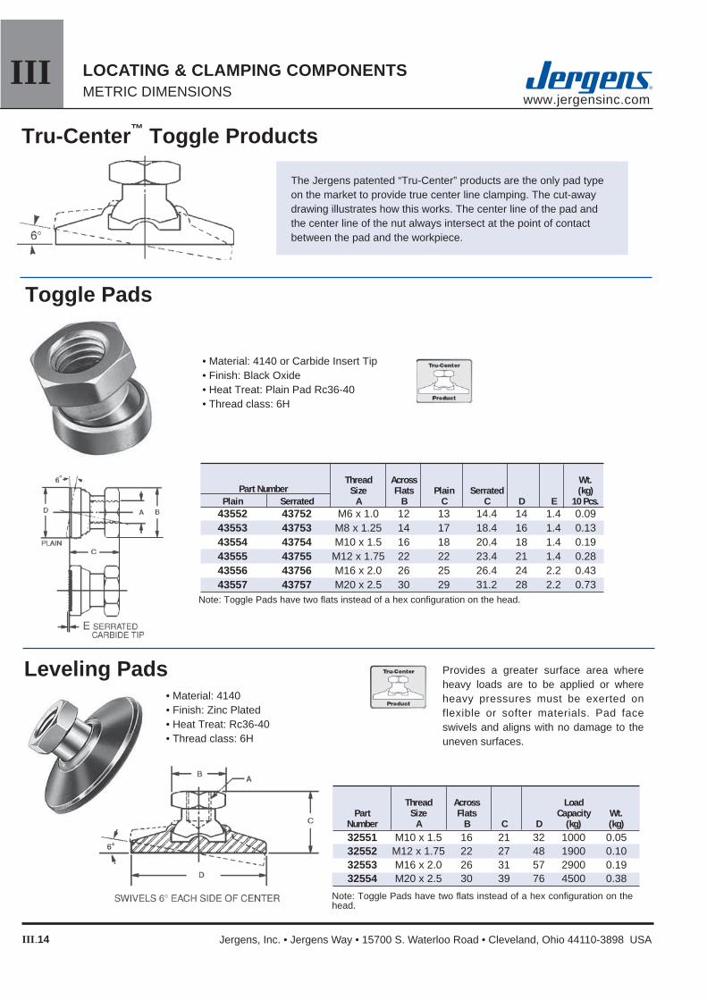
IIIwww.jergensinc.com
III.14
LOCATING & CLAMPING COMPONENTSMETRIC DIMENSIONS
Jergens, Inc. • Jergens Way • 15700 S. Waterloo Road • Cleveland, Ohio 44110-3898 USA
Tru-Center™ Toggle Products
The Jergens patented “Tru-Center” products are the only pad type on the market to provide true center line clamping. The cut-away drawing illustrates how this works. The center line of the pad and the center line of the nut always intersect at the point of contact between the pad and the workpiece.
Toggle Pads
• Material: 4140 or Carbide Insert Tip• Finish: Black Oxide• Heat Treat: Plain Pad Rc36-40• Thread class: 6H
Note: Toggle Pads have two fl ats instead of a hex confi guration on the head.
Thread Across Wt. Part Number Size Flats Plain Serrated (kg) Plain Serrated A B C C D E 10 Pcs. 43552 43752 M6 x 1.0 12 13 14.4 14 1.4 0.09 43553 43753 M8 x 1.25 14 17 18.4 16 1.4 0.13 43554 43754 M10 x 1.5 16 18 20.4 18 1.4 0.19 43555 43755 M12 x 1.75 22 22 23.4 21 1.4 0.28 43556 43756 M16 x 2.0 26 25 26.4 24 2.2 0.43 43557 43757 M20 x 2.5 30 29 31.2 28 2.2 0.73
Provides a greater surface area where heavy loads are to be applied or where heavy pressures must be exerted on flexible or softer materials. Pad face swivels and aligns with no damage to the uneven surfaces.
• Material: 4140• Finish: Zinc Plated• Heat Treat: Rc36-40• Thread class: 6H
Thread Across Load Part Size Flats Capacity Wt. Number A B C D (kg) (kg) 32551 M10 x 1.5 16 21 32 1000 0.05 32552 M12 x 1.75 22 27 48 1900 0.10 32553 M16 x 2.0 26 31 57 2900 0.19 32554 M20 x 2.5 30 39 76 4500 0.38
Leveling Pads
Note: Toggle Pads have two fl ats instead of a hex confi guration on the head.

IIIwww.jergensinc.com
III.15
LOCATING & CLAMPING COMPONENTSMETRIC DIMENSIONS
Internet Catalog: www.jergensinc.com • Email: [email protected] • Telephone +1 216 486-5540 • Fax +1 216 481-6193
Threaded
• Material: 4140• Finish: Zinc Plated• Heat Treat: Rc36-40• Thread class: 6g
Thread Across Load Part Size Flats Capacity Wt. Number A B C D (kg) (kg) 32571 M10 x 1.5 16 21 32 1000 0.07 32572 M12 x 1.75 22 27 48 1900 0.17 32573 M16 x 2.0 26 31 57 2900 0.26 32574 M20 x 2.5 30 39 76 4500 0.55
Note: Toggle Pads have two fl ats instead of a hex confi guration on the head.
Adjustable Clamp Heels
• Material: Stud, Stressproof® Pad, Low Carbon Steel• Finish: Black Oxide• Thread: 6h
Part Thread Hex Wt. Number Size A B C Size (kg) 47263 M10 x 1.5 50 16 32 5 0.09 47264 M10 x 1.5 75 16 32 5 0.11 47265 M10 x 1.5 100 16 32 5 0.11 47251 M12 x 1.75 75 16 38 6 0.11 47252 M12 x 1.75 100 16 38 6 0.13 47253 M12 x 1.75 125 16 38 6 0.15 47254 M16 x 2.0 100 19 44 8 0.25 47255 M16 x 2.0 125 19 44 8 0.29 47256 M16 x 2.0 150 19 44 8 0.32 47257 M20 x 2.5 125 22 50 10 0.44 47258 M20 x 2.5 150 22 50 10 0.46 47259 M20 x 2.5 175 22 50 10 0.55 47260 M24 x 3.0 100 25 64 14 0.44 47261 M24 x 3.0 150 25 64 14 0.50

IIIwww.jergensinc.com
III.16
LOCATING & CLAMPING COMPONENTSMETRIC DIMENSIONS
Jergens, Inc. • Jergens Way • 15700 S. Waterloo Road • Cleveland, Ohio 44110-3898 USA
Quarter Turn ScrewsThe diamond on all four corners of the Jergens Quarter Turn Screw, makes the opening and closing of jig lids easier. Ideally suited for clamping lids, covers and swing-away type bushing arms. Quarter Turn Screws may be machined for fi nishing requirements.
• Material: Stem, Low Carbon Steel Head, Low Carbon Steel• Finish: Black Oxide• Thread: Class 6g
Part Wt. Number A B C D E F (kg) 34571 M5 x 0.8 22 25 13 13 5 0.14 34573 M6 x 1.0 25 32 16 19 6 0.21 34575 M8 x 1.25 32 38 19 25 8 0.41 34577 M10 x 1.5 32 38 25 25 10 0.57 34579 M12 x 1.75 38 44 25 32 13 10.06
Thumb Screws• Material: 1215 Steel, 303 Stainless• Finish: Black Oxide• Thread: Class 6g
The half-dog point protects the threads in case of peening.
Part Wt. Number A B C D E F G (Kg)
43971 M5x0.8 30 25 23 1.2 3 20 0.20 43972 M5x0.8 45 40 35 1.2 3 20 0.21 43973 M5x0.8 55 50 45 1.2 3 20 0.22 43974 M 6 x 1.0 50 40 35 1.5 4 25 0.35 43975 M 6 x 1.0 60 50 45 1.5 4 25 0.39 43976 M 6 x 1.0 75 65 55 1.5 4 25 0.41 43977 M8 x 1.25 50 40 35 2.4 5 30 0.59 43978 M8 x 1.25 60 50 45 2.4 5 30 0.62 43979 M8 x 1.25 75 65 60 2.4 5 30 0.68 43980 M10 x 1.5 60 50 45 2.4 6 30 0.88 43981 M10 x 1.5 75 65 60 2.4 6 30 0.91 43982 M10 x 1.5 85 75 70 2.4 6 30 1.00 43983 M 12 x 1.75 90 75 70 3.0 11 30 1.27 43984 M 12 x 1.75 105 90 85 3.0 11 30 1.41 43985 M 12 x 1.75 80 65 55 3.0 11 30 1.35

IIIwww.jergensinc.com
III.17
LOCATING & CLAMPING COMPONENTSMETRIC DIMENSIONS
Internet Catalog: www.jergensinc.com • Email: [email protected] • Telephone +1 216 486-5540 • Fax +1 216 481-6193
• Material: Stressproof®
862 Tensile (MPa) 689 Yield (MPa)• Finish: Black Oxide• Longer or special studs are available on request
Studs
Thread Part A L Number N M6 x 1.0 50 37771 18 M6 x 1.0 66 37772 25 M6 x 1.0 81 37773 28 M6 x 1.0 96 37774 28 M8 x 1.25 50 37971 18 M8 x 1.25 66 37972 25 M8 x 1.25 81 37973 32 M8 x 1.25 96 37974 32 M8 x 1.25 111 37975 32 M10 x 1.5 50 38171 16 M10 x 1.5 66 38172 23 M10 x 1.5 80 38173 30 M10 x 1.5 95 38174 35 M10 x 1.5 110 38175 35 M10 x 1.5 125 38176 39 M10 x 1.5 140 38177 39 M10 x 1.5 155 38178 39 M12 x 1.75 50 38371 16 M12 x 1.75 66 38372 23 M12 x 1.75 81 38373 31 M12 x 1.75 95 38374 40 M12 x 1.75 111 38375 40 M12 x 1.75 125 38376 40 M12 x 1.75 141 38377 40 M12 x 1.75 156 38378 40 M16 x 2.0 80 38571 29 M16 x 2.0 95 38572 36 M16 x 2.0 110 38573 44 M16 x 2.0 125 38574 47 M16 x 2.0 150 38575 47 M16 x 2.0 175 38576 47 M16 x 2.0 200 38577 47 M20 x 2.5 81 38771 30 M20 x 2.5 96 38772 37 M20 x 2.5 111 38773 45 M20 x 2.5 126 38774 52 M20 x 2.5 151 38775 48 M20 x 2.5 176 38776 56 M20 x 2.5 201 38777 56
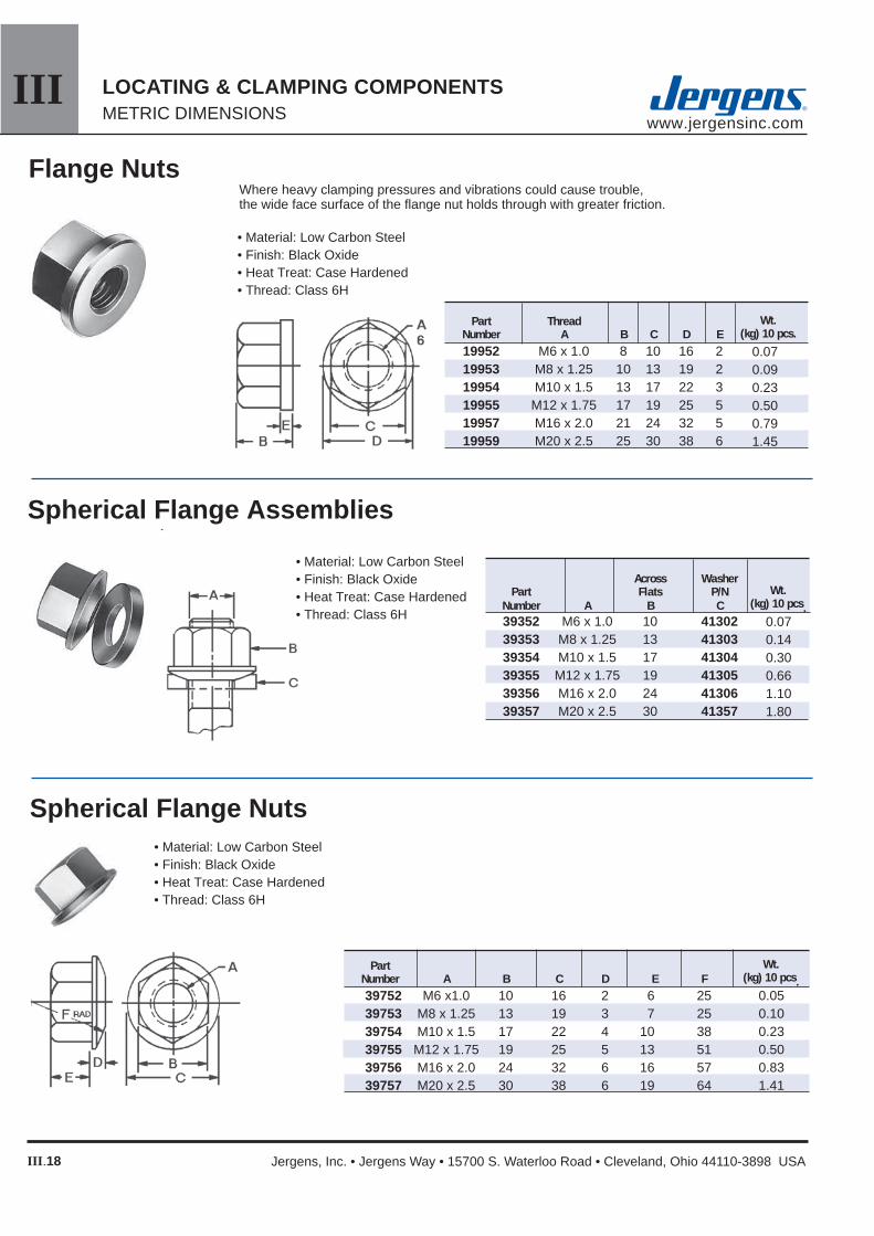
IIIwww.jergensinc.com
III.18
LOCATING & CLAMPING COMPONENTSMETRIC DIMENSIONS
Jergens, Inc. • Jergens Way • 15700 S. Waterloo Road • Cleveland, Ohio 44110-3898 USA
Where heavy clamping pressures and vibrations could cause trouble, the wide face surface of the fl ange nut holds through with greater friction.
• Material: Low Carbon Steel• Finish: Black Oxide• Heat Treat: Case Hardened• Thread: Class 6H
Flange Nuts
Wt.(kg) 10 pcs.
Part Thread Number A B C D E 19952 M6 x 1.0 8 10 16 2 19953 M8 x 1.25 10 13 19 2 19954 M10 x 1.5 13 17 22 3 19955 M12 x 1.75 17 19 25 5 19957 M16 x 2.0 21 24 32 5 19959 M20 x 2.5 25 30 38 6
0.070.090.230.500.791.45
Spherical Flange Assemblies
Across Washer Part Flats P/N Number A B C 39352 M6 x 1.0 10 41302 39353 M8 x 1.25 13 41303 39354 M10 x 1.5 17 41304 39355 M12 x 1.75 19 41305 39356 M16 x 2.0 24 41306 39357 M20 x 2.5 30 41357
• Material: Low Carbon Steel• Finish: Black Oxide• Heat Treat: Case Hardened• Thread: Class 6H
• Material: Low Carbon Steel• Finish: Black Oxide• Heat Treat: Case Hardened• Thread: Class 6H
Spherical Flange Nuts
Wt.(kg) 10 pcs.
0.050.100.230.500.831.41
Part Number A B C D E F 39752 M6 x1.0 10 16 2 6 25 39753 M8 x 1.25 13 19 3 7 25 39754 M10 x 1.5 17 22 4 10 38 39755 M12 x 1.75 19 25 5 13 51 39756 M16 x 2.0 24 32 6 16 57 39757 M20 x 2.5 30 38 6 19 64
Wt.(kg) 10 pcs.
0.070.140.300.661.101.80

IIIwww.jergensinc.com
III.19
LOCATING & CLAMPING COMPONENTSMETRIC DIMENSIONS
Internet Catalog: www.jergensinc.com • Email: [email protected] • Telephone +1 216 486-5540 • Fax +1 216 481-6193
• Free spinning installation eliminates the need to wrench the nut down the fastener.• Locks to the part, not to the threads. • Grade 8 strength and quality, and will work with any grade fastener.• Hardness of 28 - 38 HRC: more effective at maintaining clamp load under vibration.• Greater temperature range than nylon insert locknuts, and will not be effected by humidity.• Flat washers are not needed, unless in a slotted application.• Spinner grips are not limited to 5 reuses, unlike most prevailing torque lock nuts.• Jergens maintains inventory of Zinc plated product, as well as plain fi nished (un-plated) product. (Please allow 2 - 3 weeks lead time for plating.)
Spinner-Grip™ Flange Lock Nuts
Note: Additional charges apply to plated product. Charges vary by plating type.
Part Number Plain Finish Zinc Plated Thread Size A B C
19807 19827 M6-1.00 10 15.1 6.0 19808 19828 M8-1.25 13 19.0 8.8 19809 19829 M10-1.50 15 24.1 10.0 19810 19830 M12-1.75 19 25.5 11.6 19811 19831 M16-2.00 24 38.0 17.2
Coupling Nuts
• Material: Low Carbon Steel• Finish: Black Oxide• Heat Treat: Case Hardened• Thread: Class 6H
Part Wt. Number A B C (kgs) 18761 M10 25 16 0.05 18762 M12 32 19 0.08 18763 M16 41 24 0.15 18764 M20 51 27 0.26
T-Slot Nuts
• Material: Low Carbon Steel• Finish: Black Oxide• Threads: Class 6H• Heat Treat: Case Hardened
Jergens Feature:
T-slot Part Width Number Thread A B C D E Material
43372 M10x1.5 12 19 7 13 25 Steel 43373 M10x1.5 14 22 9 16 29 Steel 43374 M10x1.5 16 25 9 16 29 Steel 43375 M12x1.75 14 22 9 16 29 Steel 43376 M12x1.75 16 25 9 16 29 Steel 43377 M12x1.75 18 29 11 19 32 Steel 43378 M16x2.0 18 29 11 19 32 Steel 43379 M16x2.0 20 32 14 25 38 Steel 43380 M16x2.0 22 35 14 25 38 Steel 43381 M20x2.5 22 35 14 25 38 Steel 43382 M20x2.5 24 38 16 25 44 Steel 43383 M20x2.5 28 41 18 29 51 Steel
Jergens Table-Saver design provides a safety-stop feature to prevent turning stud into tableways.
CLASS 6H
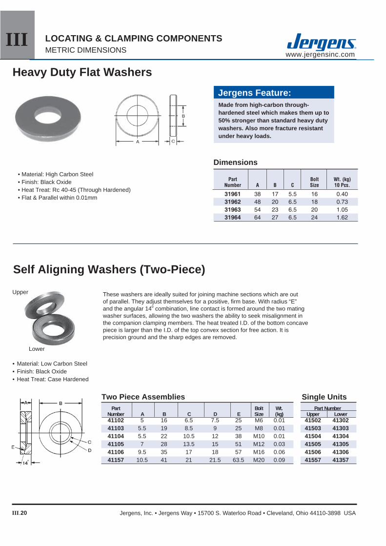
IIIwww.jergensinc.com
III.20
LOCATING & CLAMPING COMPONENTSMETRIC DIMENSIONS
Jergens, Inc. • Jergens Way • 15700 S. Waterloo Road • Cleveland, Ohio 44110-3898 USA
• Material: High Carbon Steel• Finish: Black Oxide• Heat Treat: Rc 40-45 (Through Hardened)• Flat & Parallel within 0.01mm
Heavy Duty Flat Washers
Dimensions
Jergens Feature:Made from high-carbon through- hardened steel which makes them up to 50% stronger than standard heavy duty washers. Also more fracture resistant under heavy loads.
Self Aligning Washers (Two-Piece)
• Material: Low Carbon Steel• Finish: Black Oxide• Heat Treat: Case Hardened
These washers are ideally suited for joining machine sections which are out of parallel. They adjust themselves for a positive, fi rm base. With radius “E” and the angular 140 combination, line contact is formed around the two mating washer surfaces, allowing the two washers the ability to seek misalignment in the companion clamping members. The heat treated I.D. of the bottom concave piece is larger than the I.D. of the top convex section for free action. It is precision ground and the sharp edges are removed.
Upper
Lower
Two Piece Assemblies Single Units Part Bolt Wt. Part Number Number A B C D E Size (kg) Upper Lower 41102 5 16 6.5 7.5 25 M6 0.01 41502 41302 41103 5.5 19 8.5 9 25 M8 0.01 41503 41303 41104 5.5 22 10.5 12 38 M10 0.01 41504 41304 41105 7 28 13.5 15 51 M12 0.03 41505 41305 41106 9.5 35 17 18 57 M16 0.06 41506 41306 41157 10.5 41 21 21.5 63.5 M20 0.09 41557 41357

IIIwww.jergensinc.com
III.21
LOCATING & CLAMPING COMPONENTSMETRIC DIMENSIONS
Internet Catalog: www.jergensinc.com • Email: [email protected] • Telephone +1 216 486-5540 • Fax +1 216 481-6193
The ID expansion clamp is the ideal way to hold parts on an inside diameter for multiple machining on a vertical or horizontal machining center.
The larger diameter of the clamp is held to a close tolerance for precision locating in a machined pocket on work cubes and fi xture plates.
The customer machines the mild steel clamp to match the bore of the part ensuring proper fi t. Often times the clamps can be remachined for different size jobs.
ID Expansion Clamp
• Body Material: Mild Steel• Low Profi le• Ideal for Secondary Operations
on Lathe Parts• Easily Machined to Size on
Lathe or Mill
* Three Mounting Screws Included.+ Minimum diameter the “F” dimension can be machined to.
• Excellent for Palletized Setups• Allows More Parts Per Workcube or Fixture Plate• Tighten with Hex Key or Hydraulic Pull Cylinders
(Drill clearance hole for longer bolt into hydraulic cylinder)• Instructions included with each clamp
+0.00 Part -0.05 Number A B C D E F G
+ H* I J
68830 21.8 16.0 15.0 5.9 29.72 12.4 8.0 M3 on 20.95 BHC M4 7.2 68831 24.9 19.0 15.0 5.9 31.5 14.2 12.2 M3 on 23.1 BHC M6 11.2 68832 24.9 19.0 15.0 5.9 37.5 20.0 13.5 M3 on 29.0 BHC M8 13.2 68833 28.6 22.2 17.5 6.4 50.0 27.0 18.0 M4 on 39.4 BHC M10 16.3 68834 31.8 25.4 20.6 6.4 56.0 35.3 23.0 M4 on 45.5 BHC M12 20.3 68835 39.6 31.8 27.0 7.9 69.5 42.0 29.3 M5 on 55.9 BHC M16 21.4 68836 39.6 31.8 27.0 7.9 75.5 51.5 29.3 M5 on 63.9 BHC M16 21.4 68837 45.5 37.6 32.3 7.9 107.5 77.7 29.3 M6 on 92.6 BHC M16 19.3

IIIwww.jergensinc.com
III.22
LOCATING & CLAMPING COMPONENTSMETRIC DIMENSIONS
Jergens, Inc. • Jergens Way • 15700 S. Waterloo Road • Cleveland, Ohio 44110-3898 USA
Jergens Expanding Micro Clamps allow you to fi xture more parts on your fi xture plates. The unique expanding design can hold two parts at once when used with a positive stop.• Minimizes tool changes• Holds two parts with equilateral clamping action• Ideal for clamping fl at or round work pieces• Reduces wasted space
*A shallow slot, a little wider than D dimension, will insure clamp remains in line with workpiece.
F
Expanding Micro™ Clamps
Maximum Part Thread Maximum Holding Key Number A B C D* E F† Size Spread Force (N) Size
68716 6.1 6.9 8.1 5.3 3.6 6.4 M2 6.7 880 1.5 68717 9.1 9.7 11.9 7.9 4.7 9.5 M2.5 10 1,350 2 68711 12.3 14.5 15.9 10.4 5.6 12.7 M4 13.2 2,224 3 68712 18.6 19.0 23.8 16.1 9.5 19.0 M6 20.3 6,670 5 68713 24.8 25.9 31.7 20.8 12.7 25.4 M8 26.9 8,895 6 68714 37.3 38.6 47.6 30.8 19.0 38.1 M12 39.9 15,565 10 68715 49.7 51.5 63.5 41.2 25.4 50.8 M16 53.0 26,690 14
† F is the distance needed between workpieces for clamp clearance. Drill and tap mounting hole on the center of F dimension.

IIIwww.jergensinc.com
III.23
LOCATING & CLAMPING COMPONENTSMETRIC DIMENSIONS
Internet Catalog: www.jergensinc.com • Email: [email protected] • Telephone +1 216 486-5540 • Fax +1 216 481-6193
Machinable Expanding Micro™ Clamp
The compact Machinable Expanding Micro™ Clamp is available with extra material on the clamping jaw so it can be machined to conform to the shape of your workpiece - enabling you to fi xture unusual applications easily. The specially designed steel wedge spreads the clamping force uniformly on both sides of the aluminum channel. Clamps may be ordered with a unique locking plate to make the clamp rigid while machining the jaw to your specifi cations, without vibration.
• Material: Channel 7075-76 Alumnium• Mounting Screws Included• Compact Design• Allows more parts to be mounted on Fixture
Part No. Part No. Mounting With Without ScrewLocking Plate Locking Plate A* B C D E F† G **H I
68870 68871 28.6 12.7 15.7 10.67 6.3 4.6 10.16 M2 M4 68872 68873 38.1 19.1 23.9 16.05 9.4 6.6 15.87 M4 M6 68874 68875 50.8 25.4 31.8 20.83 12.7 9.9 20.62 M4 M8 68876 68877 76.2 38.1 47.5 30.86 19.1 15.7 30.48 M5 M12 68878 68879 101.6 50.8 63.5 41.28 25.4 20.3 41.28 M6 M16
* The distance needed between workpieces for clamp clearance, drill and tap mounting holes on the center of “A” dimension.† The amount of machinable stock on jaws.** Mounting Screws Included

IIIwww.jergensinc.com
III.24
LOCATING & CLAMPING COMPONENTSMETRIC DIMENSIONS
Jergens, Inc. • Jergens Way • 15700 S. Waterloo Road • Cleveland, Ohio 44110-3898 USA
1 ....... 12mm 2 ....... 13mm 3 ....... 14mm 4 ....... 15mm 5 ....... 16mm 6 ....... 17mm
7 ....... 18mm 8 ....... 19mm 9 ....... 20mm 10 ..... 21mm 11 ..... 22mm 12 ..... 23mm
Adjustable Micro Clamps decrease design and set-up times for modular fi xtures, work cubes, and standard fi xtures. Without changing hole locations, clamping range from 12mm to 35mm can be achieved.
The clamps are available with either smooth or serrated faces which make them ideal for clamping machined parts, castings, and rough cut stock. The clamps work with a cam action, always following the contour of the workpiece for maximum surface contact.
All clamps include a cam screw. Clamps are 10mm thick.
13 ..... 24mm 14 ..... 25mm 15 ..... 26mm 16 ..... 27mm 17 ..... 28mm 18 ..... 29mm
19 ..... 30mm 20 ..... 31mm 21 ..... 32mm 22 ..... 33mm 23 ..... 34mm 24 ..... 35mm
Locking Screw is 12M for sizes; total distance of movement is 2.5mm.
Adjustable Micro™ Clamps
Measured from the centerline, each face of these low profi le clamps increases 1mm from the smallest to the largest face.
• Cam action• Low profi le• Available in four sizes• Heat treated and plated• Serrated or smooth edges• Adjustable clamps and stops• Includes Cam Screw
Part Number Description 68651 1-6 smooth 68652 7-12 smooth 68653 13-18 smooth 68654 19-24 smooth 68661 1-6 serrated 68662 7-12 serrated 68663 13-18 serrated 68664 19-24 serrated
Face #
Distance From
Center Line Face #
Distance From
Center Line Face #
Distance From
Center Line Face #
Distance From
Center Line

IIIwww.jergensinc.com
III.25
LOCATING & CLAMPING COMPONENTSMETRIC DIMENSIONS
Internet Catalog: www.jergensinc.com • Email: [email protected] • Telephone +1 216 486-5540 • Fax +1 216 481-6193
Knife edge clamps can be used for clamping rough cut stock, castings, or any material that requires a hardened clamping element. Hardened steel, brass-plated.
Jergens Micro Clamps feature both high hold down forces and low profi les, which makes them ideal for building fi xtures on Ball Lock fi xturing plates. Two simple components make them work: a hardened steel socket cap screw with an offset head and a hexagonal washer. A half turn tightens or loosens the workpiece.
Knife Edge Clamps
Micro™ Clamps
• Low profi le makes computer programming easier• Cam action provides fast, strong clamping• Small size allows more parts per load• Requires only a tapped hole in your fi xture• Available in stainless steel• Note clockwise rotation recomended workpiece
stop should be on the right of the Clamp.
Replacement Screws available, contact customer service for more information.
Replacement Screws available, contact customer service for more information.
Total Distance Part Number Part Number of Measurement Key Size Maximum Holding Steel Stainless A B C D E F G* Force (N) 68571 – M4x0.7 9.6 7.93 2.8 0.76 3 3.8 910 68572 68551 M6x1.0 11.2 15.86 4.75 1.01 4 7.8 3,558 68573 68553 M8x1.25 15.0 20.61 4.75 1.01 5 10.15 3,355 68574 – M10x1.5 19.0 20.61 6.35 1.52 7 10.15 8,895 68575 – M12x1.75 22.8 25.38 9.52 2.03 8 12.7 17,790 68576 – M16x2.0 28.5 30.13 12.69 2.54 12 15.0 26,680* This measurement is the correct location to drill and tap the hole from the edge of the work piece.
Part Maximum Holding Number A B C D E F G* Force (N)
68840 M10 7 1.52 20.60 6.35 19.0 10.15 8895 68841 M12 8 2.03 25.40 9.52 22.8 12.70 17790 68842 M16 12 2.54 30.15 12.70 28.5 15.00 26680* This measurement is the correct location to drill and tap the hole from the edge of the work piece.

IIIwww.jergensinc.com
III.26
LOCATING & CLAMPING COMPONENTSMETRIC DIMENSIONS
Jergens, Inc. • Jergens Way • 15700 S. Waterloo Road • Cleveland, Ohio 44110-3898 USA
Material:• Available in tool steel or brass• Extraordinary horizontal and
vertical force• Extremely low profi le• Very small foot print• High resistance to pull-out• Choose among three sizes with
screws• Knife and blunt edge styles
A
B
C
Lo-Profi le Micro™ Clamps
Problem: You require a clamping device which can grip low on a work piece, has exceptional horizontal and vertical holding force, and can be mounted below the fi xture plate surface.
Solution: Jergens new Lo-Profi le Micro clamps are the answer!
* Combination horizontal and vertical force.
Max.* Clamps Part Screw Holding Travel Torque Per Number Type A B C Size Force (N) (mm) (N•m) Packages
13251 Tool Steel, Knife Edge 3.81 3.55 9.52 M2.5 x .45 2,800 0.190 1.8 8 13252 Tool Steel, Blunt Edge 3.81 3.55 9.52 M2.5 x .45 2,800 0.190 1.8 8 13253 Brass, Blunt Edge 3.81 3.55 9.52 M2.5 x .45 875 0.190 0.6 8 13261 Tool Steel, Knife Edge 5.08 4.75 12.70 M4 x .70 6,600 0.406 5.6 8 13262 Tool Steel, Blunt Edge 5.08 4.75 12.70 M4 x .70 6,600 0.406 5.6 8 13263 Brass, Blunt Edge 5.08 4.75 12.70 M4 x .70 1,750 0.406 2.8 8 13271 Tool Steel, Knife Edge 7.62 7.11 19.05 M6 x 1.0 16,000 0.610 22.5 6 13272 Tool Steel, Blunt Edge 7.62 7.11 19.05 M6 x 1.0 16,000 0.610 22.5 6 13273 Brass, Blunt Edge 7.62 7.11 19.05 M6 x 1.0 4,200 0.610 5.6 6
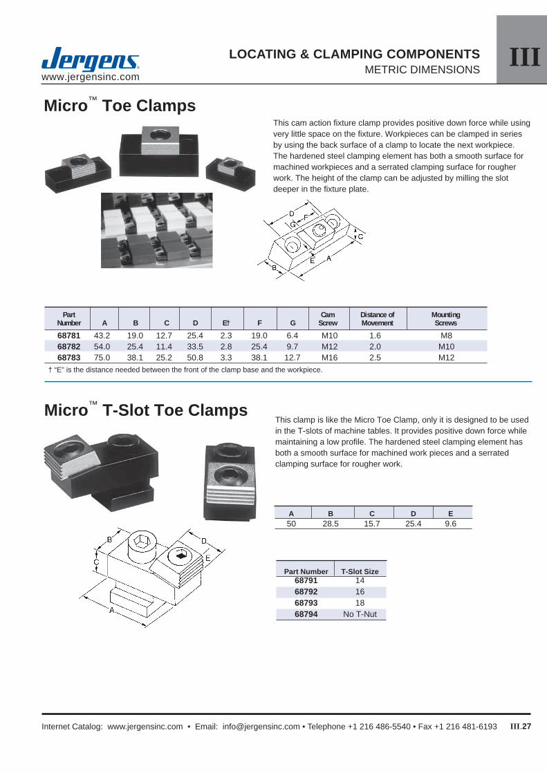
IIIwww.jergensinc.com
III.27
LOCATING & CLAMPING COMPONENTSMETRIC DIMENSIONS
Internet Catalog: www.jergensinc.com • Email: [email protected] • Telephone +1 216 486-5540 • Fax +1 216 481-6193
Micro™ T-Slot Toe Clamps
This cam action fi xture clamp provides positive down force while using very little space on the fi xture. Workpieces can be clamped in series by using the back surface of a clamp to locate the next workpiece. The hardened steel clamping element has both a smooth surface for machined workpieces and a serrated clamping surface for rougher work. The height of the clamp can be adjusted by milling the slot deeper in the fi xture plate.
This clamp is like the Micro Toe Clamp, only it is designed to be used in the T-slots of machine tables. It provides positive down force while maintaining a low profi le. The hardened steel clamping element has both a smooth surface for machined work pieces and a serrated clamping surface for rougher work.
Micro™ Toe Clamps
Part Cam Distance of Mounting Number A B C D E† F G Screw Movement Screws
68781 43.2 19.0 12.7 25.4 2.3 19.0 6.4 M10 1.6 M8 68782 54.0 25.4 11.4 33.5 2.8 25.4 9.7 M12 2.0 M10 68783 75.0 38.1 25.2 50.8 3.3 38.1 12.7 M16 2.5 M12† “E” is the distance needed between the front of the clamp base and the workpiece.
Part Number T-Slot Size 68791 14 68792 16 68793 18 68794 No T-Nut
A B C D E 50 28.5 15.7 25.4 9.6

IIIwww.jergensinc.com
III.28
LOCATING & CLAMPING COMPONENTSMETRIC DIMENSIONS
Jergens, Inc. • Jergens Way • 15700 S. Waterloo Road • Cleveland, Ohio 44110-3898 USA
The Micro Edge Clamp offers increased versatility through its unique elevated clamping abilities.• Workpiece is elevated for through milling
and drilling• Cam action provides positive holddown force• Provides fl exible set-ups for hard to hold parts• Works in plates, both with tapped hole layouts
or T-slot confi gurations• Can be mounted vertically or horizontally• Built-in stops locate workpiece for repeat
positioning• Larger sizes are ideal for mold shop applications• Tapered mounting slot prevents movement
when clamping pressure is applied
Micro™ Edge Clamps
A
B
C
D
E
D
FG
D
A
C
B
E
F
G
D
C
F
A
B
E
C
F
E
B
A
Open slot styleClosed slot style
Cam Screw Part Mounting Part Number Item A B C D E F G Number Screw Slot
68821 Clamp 63.5 19.1 15.8 11.68 8.0 21.1 13.5 68532 M8 Closed 68822 Stop 63.5 19.1 19.1 11.68 8.0 28.2 13.5 NA M8 Closed 68823 Clamp 95.3 28.5 15.8 12.19 9.4 42.7 12.7 68534 M12 Closed 68824 Stop 95.3 28.5 22.1 12.19 9.4 42.7 12.7 NA M12 Closed 68825 Clamp 107.0 38.1 41.2 35.00 9.4 46.2 NA 68535 M16 Open 68826 Stop 107.0 38.1 50.8 35.00 9.4 46.2 NA NA M16 Open
+0.0000 -0.0130