Embed Size (px)
Citation preview

BALDOR MN405 Mine Motors Operating manual http://www.manuallib.com/baldor/mn405-mine-motors-operating-manual.html
This manual contains general procedures that apply to BaldorReliance Motor products. Be sure toread and understand the Safety Notice statements in this manual. For your protection, do not install,operate or attempt to perform maintenance procedures until you understand the Warning andCautionstatements.
ManualLib.com collects and classifies the global productinstrunction manuals to help users access anytime andanywhere, helping users make better use of products.
http://www.manuallib.com

AC Water Cooled Mine Motors
(Armored Face Conveyor/Stage Loader/Crusher)
Installation & Operating Manual
8/12 MN405
This Manual:http://www.manuallib.com/baldor/mn405-mine-motors-operating-manual.html

Any trademarks used in this manual are the property of their respective owners.
This Manual:http://www.manuallib.com/baldor/mn405-mine-motors-operating-manual.html

Table of Contents
Table of Contents iMN405
Section 1General Information 1−1. . . . . . . . . . . . . . . . . . . . . . . . . . . . . . . . . . . . . . . . . . . . . . . . . . . . . . . . . . . . . . . . . . . . . . . . . . . . . . .
Overview 1−1. . . . . . . . . . . . . . . . . . . . . . . . . . . . . . . . . . . . . . . . . . . . . . . . . . . . . . . . . . . . . . . . . . . . . . . . . . . . . . . . . . . . .
Safety Notice 1−1. . . . . . . . . . . . . . . . . . . . . . . . . . . . . . . . . . . . . . . . . . . . . . . . . . . . . . . . . . . . . . . . . . . . . . . . . . . . . . . . . .
Receiving 1−2. . . . . . . . . . . . . . . . . . . . . . . . . . . . . . . . . . . . . . . . . . . . . . . . . . . . . . . . . . . . . . . . . . . . . . . . . . . . . . . . . . . . .
Handling 1−2. . . . . . . . . . . . . . . . . . . . . . . . . . . . . . . . . . . . . . . . . . . . . . . . . . . . . . . . . . . . . . . . . . . . . . . . . . . . . . . . . . . . . .
Storage 1−2. . . . . . . . . . . . . . . . . . . . . . . . . . . . . . . . . . . . . . . . . . . . . . . . . . . . . . . . . . . . . . . . . . . . . . . . . . . . . . . . . . . . . . .
EX Equipment Marking and Acceptance Instructions 1−4. . . . . . . . . . . . . . . . . . . . . . . . . . . . . . . . . . . . . . . . . . . . . . .
Section 2Installation & Operation 2−1. . . . . . . . . . . . . . . . . . . . . . . . . . . . . . . . . . . . . . . . . . . . . . . . . . . . . . . . . . . . . . . . . . . . . . . . . . .
Overview 2−1. . . . . . . . . . . . . . . . . . . . . . . . . . . . . . . . . . . . . . . . . . . . . . . . . . . . . . . . . . . . . . . . . . . . . . . . . . . . . . . . . . . . .
Installation 2−1. . . . . . . . . . . . . . . . . . . . . . . . . . . . . . . . . . . . . . . . . . . . . . . . . . . . . . . . . . . . . . . . . . . . . . . . . . . . . . . . . . . .
Alignment 2−1. . . . . . . . . . . . . . . . . . . . . . . . . . . . . . . . . . . . . . . . . . . . . . . . . . . . . . . . . . . . . . . . . . . . . . . . . . . . . . . . . . . . .
Guarding 2−1. . . . . . . . . . . . . . . . . . . . . . . . . . . . . . . . . . . . . . . . . . . . . . . . . . . . . . . . . . . . . . . . . . . . . . . . . . . . . . . . . . . . .
Power Connection 2−1. . . . . . . . . . . . . . . . . . . . . . . . . . . . . . . . . . . . . . . . . . . . . . . . . . . . . . . . . . . . . . . . . . . . . . . . . . . . .
Grounding 2−2. . . . . . . . . . . . . . . . . . . . . . . . . . . . . . . . . . . . . . . . . . . . . . . . . . . . . . . . . . . . . . . . . . . . . . . . . . . . . . . .
Conduit Box 2−2. . . . . . . . . . . . . . . . . . . . . . . . . . . . . . . . . . . . . . . . . . . . . . . . . . . . . . . . . . . . . . . . . . . . . . . . . . . . . .
AC Power 2−2. . . . . . . . . . . . . . . . . . . . . . . . . . . . . . . . . . . . . . . . . . . . . . . . . . . . . . . . . . . . . . . . . . . . . . . . . . . . . . . .
Rotation 2−2. . . . . . . . . . . . . . . . . . . . . . . . . . . . . . . . . . . . . . . . . . . . . . . . . . . . . . . . . . . . . . . . . . . . . . . . . . . . . . . . . .
DC Power 2−3. . . . . . . . . . . . . . . . . . . . . . . . . . . . . . . . . . . . . . . . . . . . . . . . . . . . . . . . . . . . . . . . . . . . . . . . . . . . . . . .
Operation 2−3. . . . . . . . . . . . . . . . . . . . . . . . . . . . . . . . . . . . . . . . . . . . . . . . . . . . . . . . . . . . . . . . . . . . . . . . . . . . . . . . . . . . .
Connection Diagrams 2−4. . . . . . . . . . . . . . . . . . . . . . . . . . . . . . . . . . . . . . . . . . . . . . . . . . . . . . . . . . . . . . . . . . . . . . . . . .
First Time Start Up 2−6. . . . . . . . . . . . . . . . . . . . . . . . . . . . . . . . . . . . . . . . . . . . . . . . . . . . . . . . . . . . . . . . . . . . . . . . . . . . .
Initial Lubrication 2−6. . . . . . . . . . . . . . . . . . . . . . . . . . . . . . . . . . . . . . . . . . . . . . . . . . . . . . . . . . . . . . . . . . . . . . . . . . . . . . .
Test for General Condition 2−7. . . . . . . . . . . . . . . . . . . . . . . . . . . . . . . . . . . . . . . . . . . . . . . . . . . . . . . . . . . . . . . . . . . . . .
Coupled Start Up 2−7. . . . . . . . . . . . . . . . . . . . . . . . . . . . . . . . . . . . . . . . . . . . . . . . . . . . . . . . . . . . . . . . . . . . . . . . . . . . . .
Jogging and Repeated Starts 2−7. . . . . . . . . . . . . . . . . . . . . . . . . . . . . . . . . . . . . . . . . . . . . . . . . . . . . . . . . . . . . . . . . . . .
Heating 2−7. . . . . . . . . . . . . . . . . . . . . . . . . . . . . . . . . . . . . . . . . . . . . . . . . . . . . . . . . . . . . . . . . . . . . . . . . . . . . . . . . . . . . . .
Hazardous Locations 2−7. . . . . . . . . . . . . . . . . . . . . . . . . . . . . . . . . . . . . . . . . . . . . . . . . . . . . . . . . . . . . . . . . . . . . . . . . . .
Selection 2−7. . . . . . . . . . . . . . . . . . . . . . . . . . . . . . . . . . . . . . . . . . . . . . . . . . . . . . . . . . . . . . . . . . . . . . . . . . . . . . . . .
Protection Concepts 2−7. . . . . . . . . . . . . . . . . . . . . . . . . . . . . . . . . . . . . . . . . . . . . . . . . . . . . . . . . . . . . . . . . . . . . . .
Repair of Motors used in Hazardous Locations 2−9. . . . . . . . . . . . . . . . . . . . . . . . . . . . . . . . . . . . . . . . . . . . . . . . . . . .
Section 3Maintenance & Troubleshooting 3−1. . . . . . . . . . . . . . . . . . . . . . . . . . . . . . . . . . . . . . . . . . . . . . . . . . . . . . . . . . . . . . . . . . . .
General Inspection 3−1. . . . . . . . . . . . . . . . . . . . . . . . . . . . . . . . . . . . . . . . . . . . . . . . . . . . . . . . . . . . . . . . . . . . . . . . . . . . .
Maintenance DC Motors Only 3−1. . . . . . . . . . . . . . . . . . . . . . . . . . . . . . . . . . . . . . . . . . . . . . . . . . . . . . . . . . . . . . . . . . .
Relubrication & Bearings 3−1. . . . . . . . . . . . . . . . . . . . . . . . . . . . . . . . . . . . . . . . . . . . . . . . . . . . . . . . . . . . . . . . . . . . . . . .
Type of Grease 3−1. . . . . . . . . . . . . . . . . . . . . . . . . . . . . . . . . . . . . . . . . . . . . . . . . . . . . . . . . . . . . . . . . . . . . . . . . . . .
Relubrication Intervals 3−1. . . . . . . . . . . . . . . . . . . . . . . . . . . . . . . . . . . . . . . . . . . . . . . . . . . . . . . . . . . . . . . . . . . . . .
Relubrication Procedure 3−2. . . . . . . . . . . . . . . . . . . . . . . . . . . . . . . . . . . . . . . . . . . . . . . . . . . . . . . . . . . . . . . . . . . .
Troubleshooting Chart 3−3. . . . . . . . . . . . . . . . . . . . . . . . . . . . . . . . . . . . . . . . . . . . . . . . . . . . . . . . . . . . . . . . . . . . . . . . . .
This Manual:http://www.manuallib.com/baldor/mn405-mine-motors-operating-manual.html

Section 1General Information
ii Table of Contents MN405
This Manual:http://www.manuallib.com/baldor/mn405-mine-motors-operating-manual.html

Section 1General Information
General Information 1−1MN405
Overview This manual contains general procedures that apply to Baldor Motor products. Be sure to read andunderstand the Safety Notice statements in this manual. For your protection, do not install, operate orattempt to perform maintenance procedures until you understand the Warning and Caution statements. A Warning statement indicates a possible unsafe condition that can cause harm to personnel. A Caution statement indicates a condition that can cause damage to equipment.Baldor mining motors are sold to OEM (Original Equipment Manufacturers) companies who providemotors and equipment containing these motors as their product offerings. Be sure to consult the OEMdocuments for safety and regulatory information that is important to the application of these products.
Important: This instruction manual is not intended to include a comprehensive listing of all details for allprocedures required for installation, operation and maintenance. This manual describes generalguidelines that apply to most of the motor products shipped by Baldor. If you have a questionabout a procedure or are uncertain about any detail, Do Not Proceed. Please contact your OEMfor more information or clarification.Before you install, operate or perform maintenance, become familiar with the following:
� IEC 34−1 Electrical and IEC72−1 Mechanical specifications.
Safety Notice: This equipment contains high voltage! Electrical shock can cause serious or fatal injury. Only qualified personnel should attempt installation, operation and maintenance of electrical equipment.Be sure that you are completely familiar with MSHA (Mine Safety and Health Administration), safetystandards for selection, installation and use of electric motors and generators and local codes andpractices. Unsafe installation or use can cause conditions that lead to serious or fatal injury. Onlyqualified personnel should attempt the installation, operation and maintenance of this equipment.
WARNING: Do not touch electrical connections before you first ensure that power has been disconnected.Electrical shock can cause serious or fatal injury. Only qualified personnel should attempt theinstallation, operation and maintenance of this equipment.
WARNING: Disconnect all electrical power from the motor windings and accessory devices beforedisassembling of the motor. Electrical shock can cause serious or fatal injury.
WARNING: Be sure the system is properly grounded before applying power. Do not apply AC power beforeyou ensure that all grounding instructions have been followed. Electrical shock can causeserious or fatal injury.
WARNING: Avoid extended exposure to machinery with high noise levels. Be sure to wear ear protectivedevices to reduce harmful effects to your hearing.
WARNING: Surface temperatures of motor enclosures may reach temperatures which can cause discomfortor injury to personnel accidentally coming into contact with hot surfaces. When installing,protection should be provided by the user to protect against accidental contact with hot surfaces.Failure to observe this precaution could result in bodily injury.
WARNING: Guards must be installed for rotating parts to prevent accidental contact by personnel.Accidental contact with body parts or clothing can cause serious or fatal injury.
WARNING: This equipment may be connected to other machinery that has rotating parts or parts that aredriven by this equipment. Improper use can cause serious or fatal injury. Only qualifiedpersonnel should attempt to install operate or maintain this equipment.
WARNING: Do not by-pass or disable protective devices or safety guards. Safety features are designed toprevent damage to personnel or equipment. These devices can only provide protection if theyremain operative.
WARNING: Be sure the load is properly coupled to the motor shaft before applying power. The shaft keymust be fully captive by the load device. Improper coupling can cause harm to personnel orequipment if the load decouples from the shaft during operation.
WARNING: Use proper care and procedures that are safe during handling, lifting, installing, operating andmaintaining operations. Improper methods may cause muscle strain or other harm.
WARNING: Pacemaker danger − Magnetic and electromagnetic fields in the vicinity of current carryingcarrying conductors and permanent magnet motors can result result in a serious health hazard topersons with cardiac pacemakers, metal implants, and hearing aids. To avoid risk, stay way fromthe area surrounding a permanent magnet motor.
WARNING: Before performing any motor maintenance procedure, be sure that the equipment connected tothe motor shaft cannot cause shaft rotation. If the load can cause shaft rotation, disconnect theload from the motor shaft before maintenance is performed. Unexpected mechanical rotation ofthe motor parts can cause injury or motor damage.
This Manual:http://www.manuallib.com/baldor/mn405-mine-motors-operating-manual.html

Section 1General Information
1−2 General Information MN405
Safety Notice ContinuedWARNING: Motors with S2 30 Minute Rating Without Coolant Flow are thermally protected. It is intended that
this duty and operation will permit repositioning of equipment in circumstances where interruptionof coolant flow may be necessary. To ensure motors do not exceed the permissible maximum surfacetemperature for Group I equipment according to IEC 60079−0 they must be operated according to theduty cycle. In addition, it is critical the installation, use and maintenance allows free flow of air aroundthe motors. Build−up of material such as coal dust that could also inhibit circulation must be removedbefore operation with this duty cycle. In addition, it is necessary to connect the motor thermalprotection devices which act as a secondary measure to provide additional assurance that thepermissible maximum surface temperature is not exceeded.
WARNING: Thermostat contacts automatically reset when the motor has slightly cooled down. To preventinjury or damage, the control circuit should be designed so that automatic starting of the motor isnot possible when the thermostat resets.
Caution: To prevent premature equipment failure or damage, only qualified maintenance personnel shouldperform maintenance.
Caution: Do not over−lubricate motor as this may cause premature bearing failure.Caution: Do not lift the motor and its driven load by the motor lifting hardware. The motor lifting hardware
is adequate for lifting only the motor. Disconnect the load (gears, pumps, compressors, or otherdriven equipment) from the motor shaft before lifting the motor.
Caution: If eye bolts are used for lifting a motor, be sure they are securely tightened. The lifting directionshould not exceed a 20 angle from the shank of the eye bolt or lifting lug. Excessive liftingangles can cause damage.
Caution: To prevent equipment damage, be sure that the electrical service is not capable of delivering morethan the maximum motor rated amps listed on the rating plate.
Caution: If a Motor Insulation test (High Potential Insulation test) must be performed, disconnect the motorfrom any Speed Control or drive to avoid damage to connected equipment.If you have any questions or are uncertain about any statement or procedure, or if you require additionalinformation please contact your OEM.
Receiving Each Baldor Electric Motor is thoroughly tested at the factory and carefully packaged for shipment. Whenyou receive your motor, there are several things you should do immediately.1. Observe the condition of the shipping container and report any damage immediately to the
commercial carrier that delivered your motor.2. Verify that the part number of the motor you received is the same as the part number listed on your
purchase order.Caution: Do not lift the motor and its driven load by the motor lifting hardware. The motor lifting hardware
is adequate for lifting only the motor. Disconnect the load (gears, pumps, compressors, or otherdriven equipment) from the motor shaft before lifting the motor.
Handling The motor should be lifted using the lifting lugs or eye bolts provided.1. Use the lugs or eye bolts provided to lift the motor. Never attempt to lift the motor and additional
equipment connected to the motor by this method. The lugs or eye bolts provided are designed to liftonly the motor. Never lift the motor by the motor shaft or hood.
2. If the motor must be mounted to a plate with the driven equipment such as pump, compressor etc., it may not be possible to lift the motor alone. For this case, the assembly should be lifted by a slingaround the mounting base. The entire assembly can be lifted as an assembly for installation. If the load is unbalanced (as with couplings or additional attachments) additional slings or othermeans must be used to prevent tipping. In any event, the load must be secure before lifting.
Storage Storage requirements for motors and generators that will not be placed in service for at least six monthsfrom date of shipment.Improper motor storage will result in seriously reduced reliability and failure. An electric motor that doesnot experience regular usage while being exposed to normally humid atmospheric conditions is likely todevelop rust in the bearings or rust particles from surrounding surfaces may contaminate the bearings. The electrical insulation may absorb an excessive amount of moisture leading to the motor windingfailure.A wooden crate “shell” should be constructed to secure the motor during storage. This is similar to anexport box but the sides & top must be secured to the wooden base with lag bolts (not nailed as exportboxes are) to allow opening and closing many times without damage to the “shell”.
This Manual:http://www.manuallib.com/baldor/mn405-mine-motors-operating-manual.html

General Information 1−3MN405
Minimum resistance of motor winding insulation is 5 Meg ohms or the calculated minimum, which ever isgreater. Minimum resistance is calculated as follows: Rm = kV + 1
where: (Rm is minimum resistance to ground in Meg−Ohms and kV is rated nameplate voltage defined as Kilo−Volts.)
Example: For a 480VAC rated motor Rm =1.48 meg−ohms (use 5 M). For a 4160VAC rated motor Rm = 5.16 meg−ohms.
Preparation for Storage1. Some motors have a shipping brace attached to the shaft to prevent damage during transportation.
The shipping brace, if provided, must be removed and stored for future use. The brace must bereinstalled to hold the shaft firmly in place against the bearing before the motor is moved.
2. Store in a clean, dry, protected warehouse where control is maintained as follows:a. Shock or vibration must not exceed 2 mils maximum at 60 hertz, to prevent the bearings from
brinelling. If shock or vibration exceeds this limit vibration isolation pads must be used.b. Storage temperatures of 10C (50F) to 49C (120F) must be maintained.c. Relative humidity must not exceed 60%.d. Motor space heaters (when present) are to be connected and energized whenever there is a
possibility that the storage ambient conditions will reach the dew point. Space heaters are optional.Note: Remove motor from containers when heaters are energized, reprotect if necessary.
3. Measure and record the resistance of the winding insulation (dielectric withstand) every 30 days ofstorage.a. If motor insulation resistance decreases below the minimum resistance, contact your OEM.b. Place new desiccant inside the vapor bag and re−seal by taping it closed.c. If a zipper−closing type bag is used instead of the heat−sealed type bag, zip the bag closed
instead of taping it. Be sure to place new desiccant inside bag after each monthly inspection.d. Place the shell over the motor and secure with lag bolts.
4. Where motors are mounted to machinery, the mounting must be such that the drains and breathersare fully operable and are at the lowest point of the motor. Vertical motors must be stored in thevertical position. Storage environment must be maintained as stated in step 2.
5. Motors with anti−friction bearings are to be greased at the time of going into extended storage withperiodic service as follows:a. Motors marked “Do Not Lubricate” on the nameplate do not need to be greased before or during
storage.b. Ball and roller bearing (anti−friction) motor shafts are to be rotated manually every 3 months and
greased every 6 months in accordance with the Maintenance section of this manual.c. Sleeve bearing (oil lube) motors are drained of oil prior to shipment.
The oil reservoirs must be refilled to the indicated level with the specified lubricant, (seeMaintenance). The shaft should be rotated monthly by hand at least 10 to 15 revolutions todistribute oil to bearing surfaces.
6. Coat all external machined surfaces with a rust preventing material. An acceptable product for this purpose is Exxon Rust Ban # 392.
7. Carbon brushes should be lifted and held in place in the holders, above the commutator, by the brushholder fingers. The commutator should be wrapped with a suitable material such as cardboard paperas a mechanical protection against damage.
Non−Regreaseable MotorsNon−regreaseable motors with “Do Not Lubricate” on the nameplate should have the motor shaft rotated15 times to redistribute the grease within the bearing every 3 months or more often.All Other Motor TypesBefore storage, the following procedure must be performed.1. Remove the grease drain plug, if supplied, (opposite the grease fitting) on the bottom of each bracket
prior to lubricating the motor.2. The motor with regreaseable bearing must be greased as instructed in Section 3 of this manual.3. Replace the grease drain plug after greasing.4. The motor shaft must be rotated a minimum of 15 times after greasing.5. Motor Shafts are to be rotated at least 15 revolutions manually every 3 months and additional grease
added every nine months (see Section 3) to each bearing.6. Bearings are to be greased at the time of removal from storage.
This Manual:http://www.manuallib.com/baldor/mn405-mine-motors-operating-manual.html

1−4 General Information MN405
Removal From Storage1. Remove all packing material.2. Measure and record the electrical resistance of the winding insulation resistance meter at the time of
removal from storage. The insulation resistance must not be less than 50% from the initial readingrecorded when the motor was placed into storage. A decrease in resistance indicates moisture in thewindings and necessitates electrical or mechanical drying before the motor can be placed intoservice. If resistance is low, contact your OEM.
3. Regrease the bearings as instructed in Section 3 of this manual.4. Reinstall the original shipping brace if motor is to be moved. This will hold the shaft firmly against the
bearing and prevent damage during movement.
EX Equipment Marking and Acceptance InstructionsATEX:If the motor is marked as shown in Figure 3-1, it is designed to comply with all European Directives ineffect at the time of manufacture, including ATEX Directive 94/9/EC, Low Voltage Directive 73/23/EEC,and EMC Directive 89/336/EEC and designed considering the Machinery Directive 98/37/ EC. It isassumed that the installation of these motors by the OE Machinery manufacturer complies with thisDirective and the standard EN 60204−1: Safety of Machinery − Electrical Equipment of Machines.
Figure 3-1 Typical AC and DC Mine Motor Markings
MFG. BY BALDOR ELECTRIC FORT SMITH, AR 72901 USA
EExd I
IP ______
FLAMEPROOF Exd ENCLOSURE
0518 613−
6−Y
D
I M2 Sira ____ ATEX _____
Any repairs by the end user, unless expressly approved by Baldor Electric Company, release BaldorElectric Company from responsibility to conformity. Authorized and qualified personnel only must performrepairs. These motors are designed in accordance with appropriate governmental regulatory agencies.They meet the technical requirements of the appropriate agencies at completion of manufacturing andhave been issued approval numbers and nameplates. Any changes to these motors, may void theseapprovals and render these motors non−conforming and dangerous for use.These motors are suitable for the ATEX Group and Category marked on the equipment nameplate. These motors are designed for normal mining applications and are in compliance with the above safetydirectives when operated within the parameters identified on the motor nameplate.Specific motor type, frame designation, model number, date code, electrical specifications, and serialnumber are marked on a separate nameplate.Special Conditions are indicated on the motor nameplate as a suffix “X” on the certificate number. Detailsof this condition can be found on the motor approval certificate.IEC, IECEx, ANZEX CERTIFICATION:If the motors are marked as Indicated below, the motors are certified to IEC60079−0 and IEC60079−1standard series. It is assumed that the installation of these motors by the OE Machinery manufacturer willbe carried out in accordance with any national requirements for the intended market. Any Repairs by theend user, unless expressly approved by Baldor Electric Company, release Baldor Electric Company fromresponsibility to conformity. Authorized and qualified personnel only must perform repairs.These motors are designed in accordance with appropriate governmental regulatory agencies. They meetthe technical requirements of the appropriate agencies at completion of manufacturing and have beenissued approval numbers and nameplates. Any changes to these motors, without the consent of BaldorElectric Company and the regulatory agencies may void these approvals and render these motorsnon−conforming and dangerous for use.These motors are suitable for Group I with a maximum surface temperature of 150C. Typical motormarking is shown in Figure 3-2.
This Manual:http://www.manuallib.com/baldor/mn405-mine-motors-operating-manual.html
General Information 1−5MN405
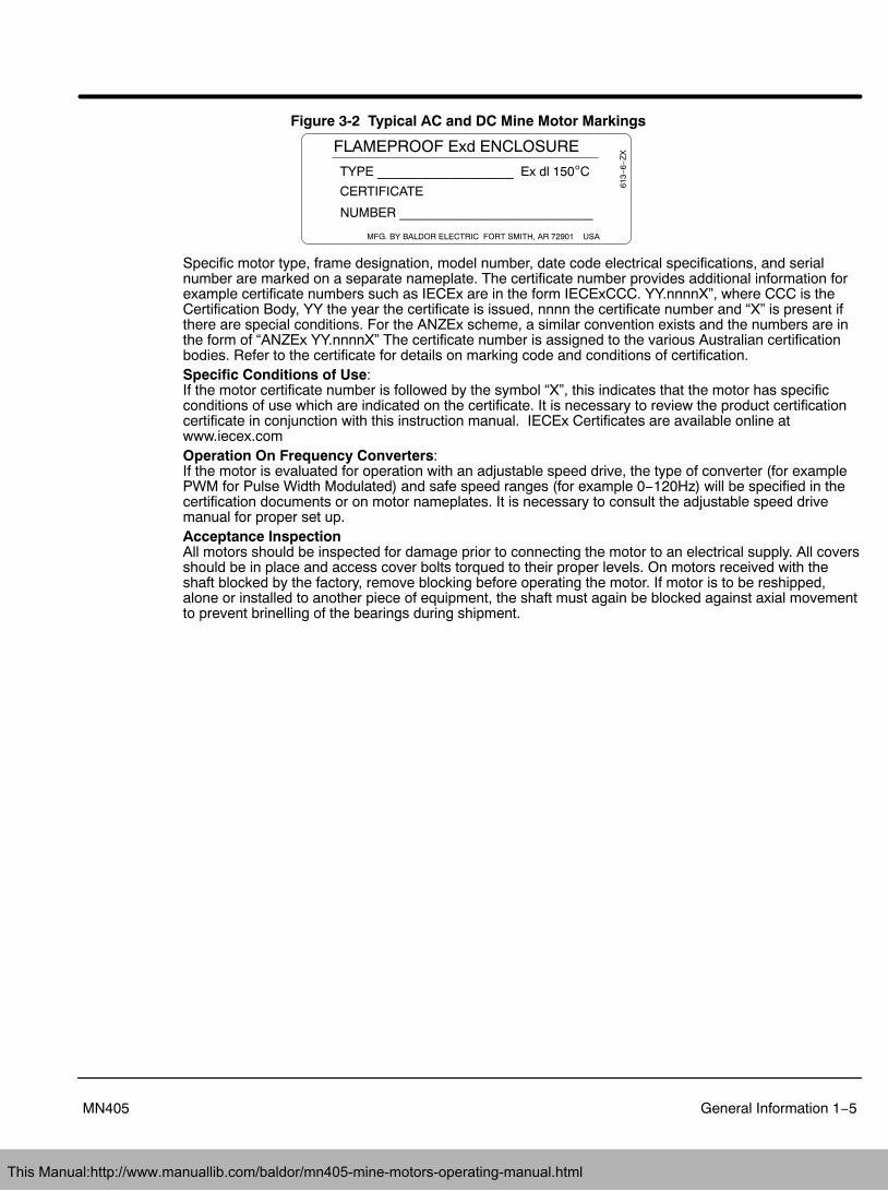
Figure 3-2 Typical AC and DC Mine Motor Markings
MFG. BY BALDOR ELECTRIC FORT SMITH, AR 72901 USA
TYPE ___________________ Ex dl 150C
CERTIFICATE
FLAMEPROOF Exd ENCLOSURE
613−
6−Z
X
NUMBER ___________________________
Specific motor type, frame designation, model number, date code electrical specifications, and serialnumber are marked on a separate nameplate. The certificate number provides additional information forexample certificate numbers such as IECEx are in the form IECExCCC. YY.nnnnX”, where CCC is theCertification Body, YY the year the certificate is issued, nnnn the certificate number and “X” is present ifthere are special conditions. For the ANZEx scheme, a similar convention exists and the numbers are inthe form of “ANZEx YY.nnnnX” The certificate number is assigned to the various Australian certificationbodies. Refer to the certificate for details on marking code and conditions of certification.Specific Conditions of Use:If the motor certificate number is followed by the symbol “X”, this indicates that the motor has specificconditions of use which are indicated on the certificate. It is necessary to review the product certificationcertificate in conjunction with this instruction manual. IECEx Certificates are available online atwww.iecex.comOperation On Frequency Converters:If the motor is evaluated for operation with an adjustable speed drive, the type of converter (for examplePWM for Pulse Width Modulated) and safe speed ranges (for example 0−120Hz) will be specified in thecertification documents or on motor nameplates. It is necessary to consult the adjustable speed drivemanual for proper set up.Acceptance InspectionAll motors should be inspected for damage prior to connecting the motor to an electrical supply. All coversshould be in place and access cover bolts torqued to their proper levels. On motors received with theshaft blocked by the factory, remove blocking before operating the motor. If motor is to be reshipped,alone or installed to another piece of equipment, the shaft must again be blocked against axial movementto prevent brinelling of the bearings during shipment.
This Manual:http://www.manuallib.com/baldor/mn405-mine-motors-operating-manual.html
1−6 General Information MN405
This Manual:http://www.manuallib.com/baldor/mn405-mine-motors-operating-manual.html

Section 2Installation & Operation
Installation & Operation 2−1MN405
WARNING: Electrostatic discharge from belts and pulleys must be eliminated prior to operation in areassubject to the risk of explosion. Explosion may result in severe injury or death.
Caution: Do not lift the motor and its driven load by the motor lifting hardware. The motor lifting hardwareis adequate for lifting only the motor. Disconnect the load (gears, pumps, compressors, or otherdriven equipment) from the motor shaft before lifting the motor.
Overview Strict compliance with all local and national laws, regulations, and practices regarding the safe operationand maintenance of underground mining equipment is necessary to assure the personal safety of thoseworking on, or around this equipment.
Caution: If eye bolts are used for lifting a motor, be sure they are securely tightened. The lifting directionshould not exceed a 20 angle from the shank of the eye bolt or lifting lug. Excessive liftingangles can cause damage.
Installation When a common base is used to mount the motor and driven equipment, do not use the lifting meansprovided on the motor. The assembly should be lifted by a sling around the base or by other lifting meansprovided on the base. Assure lifting in the direction intended in the design of the lifting means. Also use precautions to prevent hazardous overloads due to deceleration, acceleration or shock forces.Eyebolts, lifting lugs or lifting openings when provided on the motor, are intended only for lifting the motorand standard motor mounted accessories not exceeding, in total, 30% of the motor weight. These liftingprovisions should never be used when lifting or handling the motor and other equipment (i.e., gears,pumps or other driven equipment) as single unit.When the motor is an integral part of the mining machine, it should be mounted as prescribed by the OEMmanufacturer.Where motors are separately mounted, a foundation sufficiently rigid to prevent excessive vibrationshould be used.
Alignment Accurate alignment of the motor with the driven equipment is extremely important. Forcibly driving thecoupling or load onto the motor shaft will damage the bearings.After careful alignment, bolt motor securely in place. Use shims to fill any unevenness in the foundation.All motor feet should sit solidly on foundation before mounting bolts are tightened.The OEM must specify motor starter and overcurrent protection suitable for this motor and its application.Consult motor starter application data as well as applicable national and local codes.
WARNING: Guards must be installed for rotating parts to prevent accidental contact by personnel.Accidental contact with body parts or clothing can cause serious or fatal injury.
Guarding Guards must be installed for rotating parts. This is particularly important where the parts have surfaceirregularities or hot surface temperatures.
Power Connection Motor and control wiring, overload protection, disconnects, accessories and grounding shouldconform to applicable national and local codes.Frames and accessories of motors must be earth bonded in accordance with recommended national andlocal codes. Motors must be properly grounded to earth by the OE mining equipment manufacturer andby qualified electricians during the field installation of replacement motors.Connect the motor to the power supply of identical characteristics, according to the connection diagramon the motor nameplate. Use Connection Diagrams at the end of this section.This motor must be properly grounded to earth prior to operation. The motor earthing connection cable orfacility is located adjacent to the motor power terminals in the motor conduit box or lead connection area.The earthing connection must be securely tightened to prevent loosening.The machine cable providing power to the motor must incorporate an earthing conductor with a minimumcross−sectional area corresponding with the table below.
This Manual:http://www.manuallib.com/baldor/mn405-mine-motors-operating-manual.html
2−2 Installation & Operation MN405
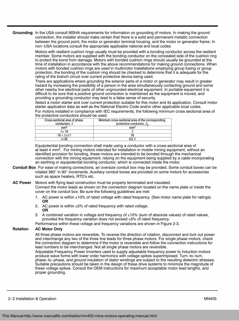
Grounding In the USA consult MSHA requirements for information on grounding of motors. In making the groundconnection, the installer should make certain that there is a solid and permanent metallic connectionbetween the ground point, the motor or generator terminal housing, and the motor or generator frame. Innon−USA locations consult the appropriate applicable national and local codes.Motors with resilient cushion rings usually must be provided with a bonding conductor across the resilientmember. Some motors are supplied with the bonding conductor on the concealed side of the cushion ringto protect the bond from damage. Motors with bonded cushion rings should usually be grounded at thetime of installation in accordance with the above recommendations for making ground connections. Whenmotors with bonded cushion rings are used in multimotor installations employing group fusing or groupprotection, the bonding of the cushion ring should be checked to determine that it is adequate for therating of the branch circuit over current protective device being used.There are applications where grounding the exterior parts of a motor or generator may result in greaterhazard by increasing the possibility of a person in the area simultaneously contacting ground and someother nearby live electrical parts of other ungrounded electrical equipment. In portable equipment it isdifficult to be sure that a positive ground connection is maintained as the equipment is moved, andproviding a grounding conductor may lead to a false sense of security.Select a motor starter and over current protection suitable for this motor and its application. Consult motorstarter application data as well as the National Electric Code and/or other applicable local codes.For motors installed in compliance with IEC requirements, the following minimum cross sectional area ofthe protective conductors should be used:
Crosssectional area of phase conductors, S
Minimum crosssectional area of the corresponding protective conductor, Sp
mm2 mm2
S< 16 S
16 < S�35 16S>35 0,5 S
Equipotential bonding connection shall made using a conductor with a cross-sectional area of at least 4 mm2. For mining motors intended for installation in mobile mining equipment, without anidentified provision for bonding, these motors are intended to be bonded through the mechanicalconnection with the mining equipment, relying on the equipment being supplied by a cable incorporatingan earthing or equipotential bonding conductor, which is connected inside the motor.
Conduit Box For ease of making connections, an oversize conduit box may be provided. Some conduit boxes can berotated 360 in 90 increments. Auxiliary conduit boxes are provided on some motors for accessoriessuch as space heaters, RTD’s etc.
AC Power Motors with flying lead construction must be properly terminated and insulated.Connect the motor leads as shown on the connection diagram located on the name plate or inside thecover on the conduit box. Be sure the following guidelines are met:1. AC power is within 10% of rated voltage with rated frequency. (See motor name plate for ratings).
OR2. AC power is within 5% of rated frequency with rated voltage.
OR3. A combined variation in voltage and frequency of 10% (sum of absolute values) of rated values,
provided the frequency variation does not exceed 5% of rated frequency.Performance within these voltage and frequency variations are shown in Figure 2-3.
Rotation AC Motor OnlyAll three phase motors are reversible. To reverse the direction of rotation, disconnect and lock out powerand interchange any two of the three line leads for three phase motors. For single phase motors, checkthe connection diagram to determine if the motor is reversible and follow the connection instructions forlead numbers to be interchanged. Not all single phase motors are reversible.Adjustable Frequency Power Inverters used to supply adjustable frequency power to induction motorsproduce wave forms with lower order harmonics with voltage spikes superimposed. Turn−to−turn,phase−to−phase, and ground insulation of stator windings are subject to the resulting dielectric stresses.Suitable precautions should be taken in the design of these drive systems to minimize the magnitude ofthese voltage spikes. Consult the OEM instructions for maximum acceptable motor lead lengths, andproper grounding.
This Manual:http://www.manuallib.com/baldor/mn405-mine-motors-operating-manual.html

Installation & Operation 2−3MN405
DC Power Check the motor nameplate and the SCR Control nameplate to be sure the voltage and type of powerrating is the same for both. The power code of the motor and power source should be the same. Theletter code for the control may be equal or less than the motor. For example a motor with a “C” powercode may be used on a supply with a “C” or “A” or less code. Table 2−1 defines these codes.
Table 2−1 Power Codes
Code DescriptionA DC Generator, battery or twelve pulse/cycle 6 phase, full controlC Six pulse/cycle, 3 phase, full control, 230VAC or 460VAC, 60Hz, input to rectifier.
When the armature power supply cannot be designated by a single letter code (A−K) the power sourcecan be determined by the code stamped on the nameplate:
M/N F−V−H−LWhere:
M Total pulses per cycleN Total controlled pulses per cycleF Free Wheeling (if used), F=used, blank=not usedV Nominal Line−to−Line voltage at input to rectifierH Line frequency (in Hz)L Value of inductance (in milli henries) to be added externally to the motor armature circuit
Example 1: “6/3 F-380-60-12” Requires a power supply with 6 total pulses per cycle, 3 controlled pulses per cycle (S-3), with freewheeling, 380 volts, 60 Hz AC input to bridge, and a 12 millihenry choke to be added externally to themotor armature circuit.Performance within these voltage and frequency variations are shown in Figure 2-3.
WARNING: Motors with S2 30 Minute Rating Without Coolant Flow are thermally protected. It is intended thatthis duty and operation will permit repositioning of equipment in circumstances where interruptionof coolant flow may be necessary. To ensure motors do not exceed the permissible maximum surfacetemperature for Group I equipment according to IEC 60079−0 they must be operated according to theduty cycle. In addition, it is critical the installation, use and maintenance allows free flow of air aroundthe motors. Build−up of material such as coal dust that could also inhibit circulation must be removedbefore operation with this duty cycle. In addition, it is necessary to connect the motor thermalprotection devices which act as a secondary measure to provide additional assurance that thepermissible maximum surface temperature is not exceeded.
Note: To provide proper cooling, always provide proper coolant flow. Before disconnecting coolant flow duringrepositioning of equipment do the following: 1) Ensure motor thermal devices are properly installed. 2) Remove anydebris on equipment and motor for maximum conduction of heat for brief periods when coolant flow is interrupted.
Operation AC and DC Mine Motors are designed to operate in a normal mining environment. Loading and operationof motors should be in accordance with the nameplate data. The motor has been designed based onrating information, application data, and duty cycle analysis provided by the OEM. Proper motor cooling isrequired for normal operation of the motor.Operation in excess of nameplate parameters is not recommended and may result in damage to theequipment and potential injury to operators and persons near the equipment. Safety related switchingused by the OEM must actuate the relevant control devices without intermediate software command.Where intermediate circuitry is involved the circuit shall fall within the scope of a safety, controlling andregulating device as defined in article 1(2) of European Directive 94/9/EC, and shall be covered by anappropriate EC Type Examination Certificate.
WARNING: These motors are designed to operate at or below the maximum surface temperature stated in theATEX directive in a normal mining application. Operation of these motors in excess of thenameplate parameters may cause the maximum allowable surface temperature to be exceeded,resulting in a risk of explosion.Temperature detection devices may be provided in these motors. The OEM determines the control setupto ensure operation within the thermal limit characteristics of the motor.The following conditions are examples of improper motor operation:1. Load imposed on the motor exceeds its nameplate value or motor power rating.2. Ambient temperatures that exceed the nameplate temperature value.3. Voltages 10% above or below the voltage(s) specified on the motor nameplate.4. Voltage unbalanced conditions.5. Insufficient or loss of coolant flow.6. Adjustable frequency operation for motors designed for sine wave power only.
This Manual:http://www.manuallib.com/baldor/mn405-mine-motors-operating-manual.html

2−4 Installation & Operation MN405
7. Altitude above 3000 ft (1000m).8. Severe duty cycles and/or repeated starts.9. Motor stall.10. Motor reversing11. Polyphase motors being operated in single phase condition12. Operating motors on variable frequency drives with operating parameters other than those specified
on the motor certification drawings13. Improper alignment of motor mounting.Note: Main power leads for CE Marked Motors may be marked U,V,W – for standard configurations,
please consult connection diagrams.Connection Diagrams
This Manual:http://www.manuallib.com/baldor/mn405-mine-motors-operating-manual.html

Installation & Operation 2−5MN405
Connection Diagrams Continued
This Manual:http://www.manuallib.com/baldor/mn405-mine-motors-operating-manual.html

2−6 Installation & Operation MN405
Figure 2-3 Typical Motor Performance VS Voltage Variations+20
+15
+10
+5
0
−5
−10
−15
−20−15 −10 −5 0 +5 +10 +15
Voltage Variations (%)
Ch
ang
es in
Mo
tor
Per
form
ance
(%
)
Full -LoadCurrent
Full -LoadCurrentPower
Factor
PowerFactor
Efficiency Efficiency
MaximumTorque
MaximumTorque
First Time Start Up Be sure that all power to motor and accessories is off. Be sure the motor shaft is disconnected fromthe load and will not cause mechanical rotation of the motor shaft.1. Make sure that the mechanical installation is secure. All bolts and nuts are tightened etc.2. If motor has been in storage or idle for some time, check winding insulation integrity.3. Inspect all electrical connections for proper termination, clearance, mechanical strength and electrical
continuity.4. Be sure all shipping materials and braces (if used) are removed from motor shaft.5. Manually rotate the motor shaft to ensure that it rotates freely.6. Replace all panels and covers that were removed during installation.7. Momentarily apply power and check the direction of rotation of the motor shaft.8. If motor rotation is wrong, be sure power is off and change the motor lead connections.
Verify rotation direction before you continue.9. Start the motor and ensure operation is smooth without excessive vibration or noise.
If so, run the motor for 1 hour with no load connected.10. After 1 hour of operation, disconnect power and connect the load to the motor shaft.
Verify all coupling guards and protective devices are installed. Ensure motor is properly ventilated.11. If motor is totally enclosed fan−cooled or non−ventilated it is recommended that condensation drain
plugs, if present, be removed. These are located in the lower portion of the end−shields. Totally enclosed fan−cooled “XT” motors are normally equipped with automatic drains which may beleft in place as received.
Initial Lubrication Baldor motors are shipped from the factory with the bearings properly packed with grease andready to operate. Where the unit has been subjected to extended storage (6 months or more) thebearings should be relubricated (regreaseable type) prior to starting. When motors are equipped for oilmist lubrication refer to the instruction manual for installation, operation, and maintenance of oil mistlubrication systems.
This Manual:http://www.manuallib.com/baldor/mn405-mine-motors-operating-manual.html

Installation & Operation 2−7MN405
Test for General ConditionIf the motor has been in storage for an extensive period or has been subjected to adverse moistureconditions, it is best to check the insulation resistance of the stator winding with a meg ohm meter. If theresistance is less than 5 meg ohms, the windings should be dried. Contact your OEM.
Coupled Start Up This procedure assumes a coupled start up. Also, that the first time start up procedure was successful.1. Check the coupling and ensure that all guards and protective devices are installed.2. Check that the coupling is properly aligned and not binding.3. The first coupled start up should be with no load. Apply power and verify that the load is not
transmitting excessive vibration back to the motor though the coupling or the foundation. Vibrationshould be at an acceptable level.
4. Run for approximately 1 hour with the driven equipment in an unloaded condition.The equipment can now be loaded and operated within specified limits. Do not exceed the name plateratings for amperes for steady continuous loads.
Jogging and Repeated Starts Repeated starts and/or jogs of induction motors generally reduce the life of the motorwinding insulation. A much greater amount of heat is produced by each acceleration or jog than by thesame motor under full load. If it is necessary to repeatedly start or jog the motor, it is advisable to checkthe application with your OEM.
Heating Duty rating and maximum ambient temperature are stated on the motor name plate. Do not exceed these values. If there is any question regarding safe operation, contact your OEM.
Hazardous LocationsHazardous locations are those where there is a risk of ignition or explosion due to the presence ofcombustible gases, vapors, dust, fibers or flyings.
Selection Facilities requiring special equipment for hazardous locations are typically classified in accordance withlocal requirements. This classification process lets the installer know what equipment is suitable forinstallation in that environment, and identifies what the maximum safe temperature or temperature classis required. It is the customer or users responsibility to determine the area classification and select properequipment.
Protection ConceptsZone 1 [Equipment Group I (mining) or Equipment Protection Level (EPL) Gb, Mb]Baldor�Reliance offers a range of motors suitable for installation in a mining environment. These motorsare known as explosion proof or flameproof. Motors that are explosion proof or flameproof use speciallymachined flameproof joints between the end bell or bracket and the frame, as well as along the rotatingshaft and at connection box covers and entries. The fit of these flameproof joints are designed to containthe combustion or quench the flame of an explosive gas atmosphere prior to it exiting the motor. Theseflameproof joints have lengths and widths selected and tested based on the gas group present in theatmosphere.These motors are not gas tight. To the contrary, this protection concept assumes that due to the normalheating and cooling cycle of motor operation that any gas present will be drawn into the motor. Sinceflameproof or explosion proof motors are designed to contain the combustion and extinguish any flametransmission, for this protection concept, only external surface temperatures are of concern. Thermallimiting devices such as thermostats, thermistors or RTDs may be provided on these motors to limit theexternal surface temperature during overload conditions.If thermostats are provided as a condition of certification, it is the installer’s responsibility to make surethat these devices are properly connected to a suitable switching device. Flameproof motors areinternationally referred to as Ex d. Representative motors are laboratory tested to verify that a flame isnot transmitted outside the motor enclosure and to determine the maximum internal pressureencountered.
This Manual:http://www.manuallib.com/baldor/mn405-mine-motors-operating-manual.html

2−8 Installation & Operation MN405
Sine Wave Power Operation for Hazardous Locations.These motors are designed to operate at or below the maximum surface temperature (or T−Code) statedon the nameplate. Failure to operate the motor properly can cause this maximum surface temperature tobe exceeded. If applied in a mining environment, this excessive temperature may cause ignition ofhazardous materials. Operating the motor at any of the following conditions can cause the markedsurface temperature to be exceeded.1. Motor load exceeding service factor nameplate value2. Ambient temperatures above nameplate value3. Voltages above or below nameplate value4. Unbalanced voltages5. Loss of proper ventilation6. Altitude above 3300 feet / 1000 meters7. Severe duty cycles of repeated starts8. Motor stall9. Motor reversing10. Single phase operation of polyphase equipment11. Variable frequency operation
Variable Frequency Power Operation for Hazardous Locations (motors with maximum surfacetemperature listed on the nameplate).Only motors with nameplates marked for use on inverter (variable frequency) power, and labeled forspecific hazardous areas may be used in those hazardous areas on inverter power. The motor isdesigned to operate at or below the maximum surface temperature (150C) stated on the nameplate.Failure to operate the motor properly can cause this maximum surface temperature to be exceeded.If applied in a mining environment, this excessive temperature may cause ignition of hazardous materials.Operating the motor at any of the following conditions can cause the marked surface temperature to beexceeded.1. Motor load exceeding service factor nameplate value2. Ambient temperature above nameplate value3. Voltage (at each operating frequency) above or below rated nameplate value4. Unbalanced voltages5. Loss of proper ventilation6. Operation outside of the nameplate speed / frequency range7. Altitudes above 3300 feet / 1000 meters8. Single phase operation of polyphase equipment9. Unstable current wave forms10. Lower than name plate minimum carrier frequency
Thermal Limiting Thermal limiting devices are temperature sensing control components installed inside the motor to limitthe internal temperature of the motor frame by interrupting the circuit of the holding coil of the magneticswitch or contactor. They are required for most Division 1 and Zone 1 applications. For Division 2 orZone 2 applications, motors should be selected that preclude running temperatures from exceeding theignition temperatures for the designated hazardous material. In Division 2 or Zone 2 classified locations,thermal limiting devices should only be used for winding protection and not considered for limiting allinternal motor temperatures to specific ignition temperatures.
Equipotential Bonding and Shaft Current ReductionLarger motors (ie WP construction) may require proper bonding between motor enclosures and covers toavoid the risk of stray currents during start up. Fastening methods and bonding straps must not be modified.Bearing currents can exist in some motors for both line−fed and inverter−fed applications. Larger line−fedmotors may require at least one insulated bearing to prevent a flow of current through the bearings. Do notdefeat such insulation whether the motor is line−fed or inverter−fed applications. Inverter−fed motors mayrequire additional bearing insulation or even a shaft brush. Do not defeat such features. When the motor andthe coupled load are not on a common conductive base plate, it may also be necessary to electrically bondtogether the stationary parts of the motor and the coupled equipment.
This Manual:http://www.manuallib.com/baldor/mn405-mine-motors-operating-manual.html

Installation & Operation 2−9MN405
Repair of Motors used in Hazardous LocationsRepair of hazardous certified motors requires additional information, skill, and care. It is the customer’sresponsibility to select service shops with proper qualifications to repair hazardous location motors.Contact the manufacture for additional repair details. Use only original manufacturer’s parts. Repair of Explosion Proof or Flame Proof Motors In the international markets using IEC based requirements, repair should be undertaken only afterconsulting IEC60079−19 Explosive Atmospheres−Part 19 Equipment repair, overhaul and reclamation. Ifuse of a certified repair facility is desired, consult the IECEx Repair Scheme at
http://www.iecex.com/service_facilities.htmExplosion proof and flameproof motors achieve their safety based on the mechanical construction −flameproof joints and bearing clearance, and the electrical design including any thermal limiting devices. Ifit is necessary to repair a flameproof or explosion proof motor, it is critical that the mechanical flameproofjoints be maintained. Consult OEM. Because this protection method also relies on temperature beingmaintained, make sure that any rewinding uses the original electrical designs, including any thermalprotection that may be present.
This Manual:http://www.manuallib.com/baldor/mn405-mine-motors-operating-manual.html
2−10 Installation & Operation MN405
This Manual:http://www.manuallib.com/baldor/mn405-mine-motors-operating-manual.html

Section 3Maintenance & Troubleshooting
Maintenance & Troubleshooting 3−1MN405
General Inspection Inspect the motor at regular intervals, approximately every 500 hours of operation or every 3months, whichever occurs first. Keep the motor clean and the ventilation openings clear. The followingsteps should be performed at each inspection:
WARNING: Do not touch electrical connections before you first ensure that power has been disconnected.Electrical shock can cause serious or fatal injury. Only qualified personnel should attempt theinstallation, operation and maintenance of this equipment.1. Check that the motor is clean. Check that the interior and exterior of the motor is free of dirt, oil,
grease, water, etc. Oily vapor, paper pulp, textile lint, etc. can accumulate and block motorventilation. If the motor is not properly ventilated, overheating and early failure can occur.
2. Perform a dielectric with stand test periodically to ensure that the integrity of the winding insulationhas been maintained. Record the readings. Immediately investigate any significant decrease ininsulation resistance.
3. Check all electrical connectors to be sure that they are tight.Maintenance DC Motors Only
Brush pressure is correctly established at the factory and maintained at the correct value throughout thelife of the brush by means of a constant pressure design. Brushes and brush holders should be clean toallow brushes to move freely in the holders. Replace brushes with new brushes of the same grade beforewear permits the rivet or tamped pigtail to score the commutator. It is recommended to replace allbrushes at one time.
Relubrication & Bearings Bearing grease will lose its lubricating ability over time, not suddenly. The lubricatingability of a grease (over time) depends primarily on the type of grease, the size of the bearing, the speedat which the bearing operates and the severity of the operating conditions. Good results can be obtainedif the following recommendations are used in your maintenance program.
Type of Grease A high grade ball or roller bearing grease should be used. Use only OEM recommended grease.Do not mix greases unless compatibility has been checked and verified.
Relubrication Intervals Recommended relubrication intervals are shown in Table 3-2. It is important to realize thatthe recommended intervals of Table 3-2 are based on average use.
Refer to additional information contained in Tables 3-3 and 3-4.
Table 3-2 Relubrication Intervals *
Rated Power Lubrication Frequency1 − 10kW, 1800RPM 6 months11 − 100kW, 1800RPM 3 months>100kW, 1800RPM 1 monthAll >1800 RPM 1 month
* Relubrication intervals are for ball bearings. For roller bearings, divide the relubrication interval by 2.
** For motors operating at speeds greater than 3600 RPM, contact OEM for relubrication recommendations.
This Manual:http://www.manuallib.com/baldor/mn405-mine-motors-operating-manual.html

3−2 Maintenance & Troubleshooting MN405
Table 3-3 Service Conditions
Severity of Service Hours per dayof Operation
Ambient TemperatureMaximum
AtmosphericContamination
Standard 8 40 C Clean, Little CorrosionSevere 16 Plus 50 C Moderate dirt, CorrosionExtreme 16 Plus >50 C or
Class H InsulationSevere dirt, Abrasive dust, Corrosion, Heavy
Shock or VibrationLow Temperature <−29 C
Table 3-4 Relubrication Interval Multiplier
Severity of Service MultiplierStandard 1.0Severe 0.5Extreme 0.1
Low Temperature 1.0
Some motor designs use different bearings on each motor end. This is normally indicated on the motor nameplate. In this case, the larger bearing is installed on the motor Drive endplate. For best relubrication results, only use theappropriate amount of grease for each bearing size (not the same for both).
Caution: To avoid damage to motor bearings, grease must be kept free of dirt. For an extremely dirtyenvironment, contact your OEM for additional information.
Relubrication Procedure Be sure that the grease you are adding to the motor is compatible with the grease alreadyin the motor. Consult OEM if a grease other than the recommended type is to be used.
Caution: Do not over−lubricate motor as this may cause premature bearing failure.With Grease Outlet Plug1. With the motor stopped, clean all grease fittings with a clean cloth.2. Remove grease outlet plug.
Caution: Over−lubricating can cause excessive bearing temperatures, premature lubrication breakdownand bearing failure.3. Add the recommended amount of grease.4. Operate the motor for 15 minutes with grease plug removed.
This allows excess grease to purge.5. Re-install grease outlet plug.Without Grease Provisions1. Disassemble the motor.2. Add recommended amount of grease to bearing and bearing cavity. (Bearing should be about 1/3
full of grease and outboard bearing cavity should be about 1/2 full of grease.)3. Assemble the motor.
Sample Relubrication Determination
Assume - NEMA 286T (IEC 180), 1750 RPM motor driving an exhaust fan in an ambient temperature of43 C and the atmosphere is moderately corrosive.1. Table 3-2 list 9500 hours for standard conditions.2. Table 3-3 classifies severity of service as “Severe”.3. Approximately 1.2 in3 or 3.9 teaspoon of grease is to be added.Note: Smaller bearings in size category may require reduced amounts of grease.
This Manual:http://www.manuallib.com/baldor/mn405-mine-motors-operating-manual.html

Section 1General Information
Maintenance & Troubleshooting 3−3MN405
Table 3-5 Troubleshooting Chart
Symptom Possible Causes Possible SolutionsMotor will not start Usually caused by line trouble, such
as, single phasing at the starter.Check source of power. Check overloads, fuses,controls, etc.
Excessive humming High Voltage. Check input line connections.Eccentric air gap. Have motor serviced at local Baldor service center.
Motor Over Heating Overload. Compare actual amps(measured) with nameplate rating.
Locate and remove source of excessive friction inmotor or load.Reduce load or replace with motor of greater capacity.
Single Phasing. Check current at all phases (should be approximatelyequal) to isolate and correct the problem.
Improper ventilation. Check external cooling fan to be sure air is movingproperly across cooling fins.Excessive dirt build-up on motor. Clean motor.
Unbalanced voltage. Check voltage at all phases (should be approximatelyequal) to isolate and correct the problem.
Rotor rubbing on stator. Check air gap clearance and bearings.Tighten “Thru Bolts”.
Over voltage or under voltage. Check input voltage at each phase to motor.Open stator winding. Check stator resistance at all three phases for
balance.Grounded winding. Perform dielectric test and repair as required.Improper connections. Inspect all electrical connections for proper
termination, clearance, mechanical strength andelectrical continuity. Refer to motor lead connectiondiagram.
Bearing Over Heating Misalignment. Check and align motor and driven equipment.Excessive belt tension. Reduce belt tension to proper point for load.Excessive end thrust. Reduce the end thrust from driven machine.Excessive grease in bearing. Remove grease until cavity is approximately 3/4 filled.Insufficient grease in bearing. Add grease until cavity is approximately 3/4 filled.Dirt in bearing. Clean bearing cavity and bearing. Repack with correct
grease until cavity is approximately 3/4 filled.Vibration Misalignment. Check and align motor and driven equipment.
Rubbing between rotating parts andstationary parts.
Isolate and eliminate cause of rubbing.
Rotor out of balance. Have rotor balance checked are repaired at yourBaldor Service Center.
Resonance. Tune system or contact your Baldor Service Centerfor assistance.
Noise Foreign material in air gap orventilation openings.
Remove rotor and foreign material. Reinstall rotor.Check insulation integrity. Clean ventilation openings.
Growling or whining Bad bearing. Replace bearing. Clean all grease from cavity andnew bearing. Repack with correct grease until cavityis approximately 3/4 filled.
This Manual:http://www.manuallib.com/baldor/mn405-mine-motors-operating-manual.html

3−4 Maintenance & Troubleshooting MN405
This Manual:http://www.manuallib.com/baldor/mn405-mine-motors-operating-manual.html

This Manual:http://www.manuallib.com/baldor/mn405-mine-motors-operating-manual.html

This Manual:http://www.manuallib.com/baldor/mn405-mine-motors-operating-manual.html
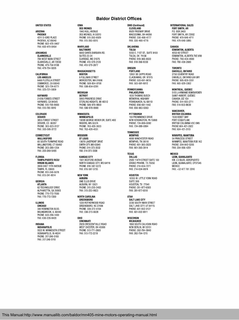
Baldor District Offices
This Manual:http://www.manuallib.com/baldor/mn405-mine-motors-operating-manual.html

2009 Baldor Electric CompanyMN405
All rights reserved. Printed in USA8/12
BALDOR ELECTRIC COMPANYWorld Headquarters
P.O. Box 2400 Fort Smith, AR 72901−2400(479) 646−4711 Fax (479) 648−5792
www.baldor.com
This Manual:http://www.manuallib.com/baldor/mn405-mine-motors-operating-manual.html