Embed Size (px)
Citation preview

IEEE TRANSACTIONS ON COMPUTER-AIDED DESIGN OF INTEGRATED CIRCUITS AND SYSTEMS, VOL. 22, NO. 12, DECEMBER 2003 1597
BALBOA: A Component-Based DesignEnvironment for System Models
Frederic Doucet, Student Member, IEEE, Sandeep Shukla, Senior Member, IEEE, Masato Otsuka, andRajesh Gupta, Senior Member, IEEE
Abstract—This paper presents the BALBOA component com-position framework for system-level architectural design. It hasthree parts: a loosely-typed component integration language(CIL); a set of C++ intellectual property (IP) component libraries;and a set of split-level interfaces (SLIs) to link the two. A CILcomponent interface can be mapped to many different C++component implementations. A type-inference system maps allweakly-typed CIL interfaces to strongly typed C++ componentimplementations to produce an executable architectural model.Thus, this amounts to selecting IP implementations accordingto a set of connection constraints. The SLIs are used to select,adapt, and validate the implementation types. The advantageof using the CIL is that the design description sizes are muchsmaller because the runtime infrastructure automatically selectsthe IP and communication implementations. The type inferencefacilitates changes by automatically propagating them throughthe design structure. We show that the inference problem is NPcomplete and we present a heuristic solution to the problem.We bring forth a number of issues related to the automation ofreusable IP composition including type- compatibility checking,split-programming, and introspective composition environment,and demonstrate their utility through design examples.
Index Terms—Hardware/software co-design, system-on-chip,embedded systems, hardware description language (HDL), mod-eling, simulation, design reuse, interface design.
I. INTRODUCTION
RAISING the abstraction levels at which microelectronicsystem designs are entered and validated has a direct
impact on the design quality and design time [1]. Consequently,recent research efforts in the area have been focused on thespecification methodologies and languages for system-level
Manuscript received March 23, 2002; revised September 29, 2002. This workwas supported in part by the Semiconductor Research Corporation through aGraduate Fellowship, in part by the Fonds de Recherche sur la Nature et laTechnologies of the Province of Quebec pour la Nature through a Graduate Fel-lowship, in part by the Cal-MICRO program in partnership with Conexant, andin part by the National Science Foundation. This paper was recommended byAssociate Editor R. Camposano.
F. Doucet was with the Center for Embedded Computer Systems, Universityof California, Irvine, CA 92697 USA. He is now with the Department of Com-puter Science and Engineering, University of California at San Diego, La Jolla,CA 92093–0114 (e-mail: [email protected]).
S. Shukla is with the Bradley Department of Electrical and Computer En-gineering, Virginia Polytechnic Institute and State University, Blacksburg, VA24060 USA (e-mail: [email protected]).
M. Otsuka is with the Design Verification Department, Technology Devel-opment Division, LSI Group, Fujitsu Ltd., Kawasaki, 211-8588, Japan (e-mail:[email protected]).
R. Gupta is with the Department of Computer Science and Engineering, Uni-versity of California at San Diego, La Jolla, CA 92093-0114 USA (e-mail:[email protected]).
Digital Object Identifier 10.1109/TCAD.2003.819385
design. One prevailing view is to use C/C++, or a similargeneral purpose high-level programming language [2], to buildcustom architecture exploration and analysis frameworks. Inthe recent years, there have been several such proposals tohelp build digital hardware systems. Examples are SystemC[3], [4], SpecC [5], Ocapi [6], and others [7]–[10]. However,design composition is still tedious and reuse isad hoc inthe current compile-link-test methodologies. This is becauseC/C++ is a software implementation language, not hardware orsystem description language. A major barrier to its adoptionfor system-level design is that hardware designers need tounderstand significant software engineering issues related to“components” in software models. Often, such concerns arequite orthogonal to hardware system architectures and designissues, thus, actually adding to the time and effort in the systemdesign process. For instance, strong typing requirements inC++ place a programming burden on the system architect toensure that the component models and there interfaces areproperly matched. The need to explicitly specify all typinginformation for components and their connections makeschanges difficult. This is particularly notable when integratingpredefined intellectual property (IP) components, where theavailability of different data types for ports may be restricted,depending upon how the component has been modeled inC++. At the same time, there is a definite need to leveragethe advantages of programming languages to quickly andaccurately build executable system models.
In this context, our goal is to reduce as much as possible thesoftware engineering and C++ programming problems facedby a system architect/integrator. To achieve this, a componentcomposition framework provides reasoning capabilities andtools that enable a system designer to compose componentsinto a specific application. These capabilities include selectionand connection of the correct components, automated creationof correct interfaces, simulation of the composed design,testing and validation for behavioral correctness and equiv-alence checks. We built a system-level design environmentcalled BALBOA which is a prototype component compositionframework based on C++ class libraries approaches. BALBOA
is used at the architectural level to design, evaluate and testfunctionality and performance. We use C++ for IP componentdefinition, but we introduce a component integration language(CIL) for efficient architectural design. The CIL is a script-likelanguage used to manipulate and assemble C++ objectsincrementally and run simulations quickly without havingto go through tedious recompilations cycles. CIL constructsprovide an abstraction over C++ because they reduce theamount of typing information required to declare component
0278-0070/03$17.00 © 2003 IEEE

1598 IEEE TRANSACTIONS ON COMPUTER-AIDED DESIGN OF INTEGRATED CIRCUITS AND SYSTEMS, VOL. 22, NO. 12, DECEMBER 2003
instances and connections. Using the CIL, a system architectcan declare component instances with their interface typespartially specified. We call this capability “partial-typing” (orloose-typing). Component integration can be done with partialtypes, but component execution needs full exact types. This isbecause a CIL design is simulated through an underlying C++model (which cannot be done without instantiating the correctC++ objects).
In the BALBOA runtime environment, a type system auto-matically transforms the abstract CIL specification into a cor-rect C++ implementation. The type system is responsible for1) keeping track of the types of all specified components and2) linking partially-typed component interfaces to fully-typedimplementations. A type inference along the component con-nections in the design architecture is used to determine whichC++ implementation types to assign to which CIL componentinterfaces.
Within the composition environment, a split-level interface(SLI) links a weakly typed interface to a strongly typed objectimplementation. The SLI provides the component-level imple-mentation of the type system which includes the following in-formation: 1) CIL interface type; 2) available C++ implementa-tions; and 3) valid interface-to-implementation mappings withrespect to all connections. The SLI provides a reflective layer,where all the interface- and implementation-type informationis captured and accessible. This type information describes andimplements the component composition rules. The system ar-chitect and the type inference can query this information to un-derstand exactly what types are being manipulated. We call thisthe introspection capability and it is used by the type inferenceto produce a valid implementation selection.
The major contributions of this work are as follows. We havedeveloped a component composition framework, which allowsa clear separation between component definition and architec-ture elaboration. In the BALBOA environment, the level of ab-straction is raised because the type dependencies between com-ponents are weaker when using the CIL than when using C++.The type inference lets system architects concentrate on archi-tectural issues, rather than worrying about matching C++ types.
This paper is organized as follows. In Section II, we reviewdefinitions, background, and related work. Section III describesthe BALBOA component composition environment, its usage,and implementation. Section IV presents the syntax and usage ofthe CIL and the BALBOA interface description language (BIDL).Section V describes the theory and implementation of the typeabstraction and inference systems. In Section VI, we show howthe CIL is used by a system architect as a front-end language. Wepresent an implementation of a moderately complex design ofan adaptive memory platform, called AMRM [11], in the envi-ronment and we discuss the results. We conclude in Section VIIalong with the description of the future work.
II. DEFINITIONS, BACKGROUND, AND RELATED WORK
The target of our work is microelectronic systems modelingfor integrated design implementations. This integration (es-pecially for single chip implementations) requires completesystem-level simulations and verification of the systems.Accordingly, this work is based on advances in component
based design in software engineering, design specificationlanguages and methodologies, and advances in type resolutionin programming languages. We briefly review these advances.
A. Component-Based Design and Reuse
A component can be a piece of functionality implemented insoftware or as a dedicated piece of silicon hardware or a com-bination of the two. Components are units of composition andreuse—be it a function, object, library, or a complete program[12]. Usually, we can assume that a component will implementan interface to which another component will be connected.An interface is a “contract” between a component and its en-vironment, a guarantee as a point of access. When establishinga connection, one component assumes that the interface of theother component implements the expected guarantees. Compo-nent technology is emphasized as a key element in the develop-ment of complex software systems [13]. Research in softwareengineering has demonstrated that the focus of the program-ming work is different when building components than whenbuilding architectures [14]. A component-based design (CBD)approach separates component definition from component com-position. CBD is a bottom-up activity of assembling small com-ponents focused on one task into a more complex componentwith richer functionality. Reuse and parameterization have al-ways been concerns when building components. Inheritance isused to share interface and behavior definitions, while poly-morphism is used for defining several behaviors for the sameinterface. However, building architectures is done structurally,through instantiations and connections.
Reusability in architectures requires not only matching of in-terfaces, but also an ability to compose the functionalities in away that correctly implements the end application. The diffi-culty of composition is due to the various ways in which theblocks can be represented, designed, and composed. This is es-pecially true when considering microelectronic system mod-eling frameworks. The semantics of connections change be-tween all levels of abstractions. At high levels, the amount ofcomputation encapsulated behind an interface is much greaterthan at lower levels, but the structural design scope is muchsmaller. Different levels of abstraction can often be composedusing protocol modules. The composability of models can be de-fined along a number of modeling dimensions, which describewhat details are captured, to what level of accuracy, and howtheir modeling semantics are implemented (which syntax/con-trol flow) [15].
B. System-Level Design and Architectures
System-level and hardware specification languages are activeareas of research. Most approaches are based on programminglanguage and raise the level of abstraction above register transferlevel (RTL) into either the architectural and behavioral spacesdesign [16]–[19]. SpecC [5] and SystemC [4] are approachesthat are based on the C/C++ programming languages. One of theproblems is that many programming decisions and syntacticaldetails that have to be addressed in C/C++ are independent ofthe system architecture model. Hardware designers and systemintegrators need not be concerned with inheritance, virtual func-tion, genericity, and other tedious C++ specific constructs used

DOUCETet al.: BALBOA: COMPONENT-BASED DESIGN ENVIRONMENT FOR SYSTEM MODELS 1599
in module definition. Rather they should focus on characteris-tics specific to hardware such as bit width, propagation delays,regularity, etc.
There has been recent research about using component-basedmethodologies for system-level design. The results have shownsignificant reductions in design size and time required for auto-matic communication refinement. Approaches by Cesarioet al.[20] and by researchers working on the Coral [21] frameworkstart from a virtual architecture consisting of virtual componentand virtual connections configured with sets of parameters. Amicroarchitecture implementation is generated by configuringthe interface logic with respect to the configuration parame-ters. This can be done in two ways. The first one is compar-ison and matching of interface pin properties to find connec-tion compatibilities and exact matches. Compatible pins can beconnected with small interface logic like multiplexers, whilepins with exact matches can be connected directly. The secondtechnique is by channel refinement. A component will refine aread()/write() interface using method calls to communicate witha read()/write() interface implementing signal-level activity forbus transactions. The interface for the component will stay thesame, albeit, it will take more cycle to perform a transaction.However, the interface will be connected to a bus instead ofbeing connected directly to the recipient of the communication.This approach is sometimes called “transaction-level modeling”because transactions are decomposed from one event betweencomponents to many events on the bus. Both CBD strategiesare platform-based design (PBD) approaches [22]. PBD is oftendefined as the creation of a stable core-based or bus-based archi-tecture that can be rapidly extended and customized for a rangeof applications and quickly delivered to the customer for de-ployment. This requires a “standard” architecture or protocolto which components are interfaced. PBD provides structure topure CBD through architectural constraints on system-on-chip(SOC) implementations. In other words, it provides the archi-tectural template, and wrappers can be picked from libraries toimplement the necessary protocols to which a component mustconform.
Another well-known component framework is Ptolemy [23],which is targeted for system simulation and embedded soft-ware design. In Ptolemy, components are executed accordingto different models of computation. Components with their ownthread of control are called “actors.” In an execution, the actorsinteract according to different models of computation (called“domains”). A model of computation is a collection of rulesdescribing patterns for component executions and communica-tions. Examples are data flow graphs, finite state machines, petrinets, etc. Domain-specific “directors” resolve the domain-de-pendent interactions and coordinate the actors from differentdomains. In Ptolemy, the different models of computation [24]are described using state machine [25]. The compatibility oftwo domains is determined by the output of the composition oftheir state machines. If they are compatible, the output will be acommon state machine coordinating both domains.
All these approaches use components libraries, but they differin the way the components are assembled. We identified threestrategies for component integration. The first one is to com-pose components directly in the programming language used
for components definitions. This is the approach used with Sys-temC and Ocapi. In these cases, the code for setup and simu-lation is interleaved with the code for component definitions,thus making maintenance and reuse difficult. The second ap-proach is to use a graphical capture tool with a notation of blocksand arrows (such as UML [26]) as a front end for code gener-ation. The third approach is to use an architecture descriptionlanguage (ADL) [27], which orthogonolize component defini-tion from system architecture composition [28]. ADLs are oftendomain-specific languages used to build an abstract model of asystem and analyze it for schedulability, reliability, deadlock de-tections, etc. For system level-designs, ADLs have long focusedon specialized tasks [29] such as processor descriptions [30].
Software implementations in C/C++/Java/Ada can be gener-ated from several ADL models [31]. Code generation is usefulbecause platform-independent architectural descriptions can beanalyzed and targeted to specific machine. In this kind of ADL,component composition is usually done statically at the designtime through code generation. Examples are Giotto [32] andPecos [33]. There are other ADLs, such as Weaves [34], thatdo not use code generation, but dynamic composition, wherecomponents acquire references to each other at runtime. Theadvantage of dynamic composition over static composition isthat the object relationships defined at runtime have weaker de-pendencies because they can be redirected, altered, and maskeddynamically increasing flexibility and reuse [35].
There is another class of ADLs which are based on XML.These are declarative languages used for data exchange betweentools. The MoML [36] XML dialect is used for describing andstoring Ptolemy models. MoML incorporates system-level se-mantics to capture system architectures as actor topologies, hi-erarchies and relations. Such ADLs are used by programs be-cause they are very easy to parse and generate. However, theyare hard to read and usually not used by designers, as opposedto the other ADLs enumerated above.
Interoperability between design environments using ADLscan be difficult [15] because the ADLs often cover only somespecific semantics of the “middleware”—the underlying com-putation model. In other words, an ADL that does not expressall details of a design can be difficult to interoperate.
C. Split-Programming Techniques and Script Languages
Scripting is used to assemble components into applicationswhere quick prototyping and flexibility are required. Scriptinghas been used for many years for component integration in com-puter-aided design frameworks as a sort of a module intercon-nection language. Script languages encapsulate APIs [37] be-hind an interpreted layer to reduce type dependencies. In the Tclscripting language, variables have loose types because they canstore any value that can be formatted back and forth to a string.
Split-level programming refers to architectural systemintegration and component programming in two different levelsthat are strongly connected by a matching class hierarchy andmethods [37]. Split-level programming relieves the systemengineers of programming artifacts and software engineeringconcerns specific to component implementation, and lets them
1600 IEEE TRANSACTIONS ON COMPUTER-AIDED DESIGN OF INTEGRATED CIRCUITS AND SYSTEMS, VOL. 22, NO. 12, DECEMBER 2003
focus on system architecture. The key is to have the class hier-archies in multiple programming environments with “hooks”that enable their combined manipulation [38]. The networksimulator (NS) system uses a split-programming model builton scripting to create a network simulation environment. InNS, there are two layers of programming facilities: one forbuilding network components and the other for composing andsimulating them. C++ is used for defining components thatare used in an object Tcl (OTcl)-based scripting language tobuild and simulate a network topology model. The C++ classesthat implement network components inherit from an OTcl baseclass that provides the hooks to be visible in the scripting layer[39].
Setting up a scripting environment to manipulate a C++ ob-ject can be cumbersome. A popular and efficient way to do itis by using a “wrapper generator” such as Swig. The Swig tool[40], [41] generates a wrapper around a C++ object to imple-ments the script commands to instantiate/delete objects, accessattributes, and invoke methods. The procedure is easy and effi-cient and the wrapper is transparent to the script user. However,in most CBD environments, the components are not simple ob-jects, but they have complex internal architectures and behaviors[42]. Swig provides access to the C++ object, but it is not pos-sible to configure and change the wrapper. Furthermore, Swigdoes not provide explicit support for a type system, runtime typeconstruction, and type introspection. Also, there are a number oflimitations when considering subtyping strategies, such as tem-plates, parameterization, and inheritance. In the context of theBALBOA work, the partial-typing abstraction and type inferencerequires access to the wrapper and to a type system.
D. Type Systems
Most of the current system-level languages are stronglytyped, with the exception of the Ptolemy framework which hasan elaborate type system [43]. Ptolemy provides polymorphicactors, whose ports can have polymorphic types, i.e., they canbe parameterized to take different combination of data types.Static type checking can determine the compatibility of a setof component interconnections. The polymorphism of actorsis based on a lossless type hierarchy that forms a lattice. Forinstance, an integer type can be coerced losslessly into a doublebecause double is higher in partial order than integer. Thismeans that the value range of a double data type includes thevalue range of an integer data type. This value range inclusionproperty is used to put the data types in a lattice. Over thislattice, the static type resolution can be reduced to a solutionof horn-clauses [44]. Thus, it is solved in linear time [43] by afixed-point computation, which is a common way of computingtype inference [45]. However, in order to be able to solve thetype inference this way, Ptolemy requires the following. First,third-party actors need to conform to the polymorphic actordesign principles—they must derive from a Ptolemy class orbe wrapped in another Ptolemy actor. Second, port types aretaken from the Ptolemy type library which conform to the typelattice structure. Unfortunately, for many silicon IP components(including legacy components), there are constraints on theavailability of specific port types, either due to hardware designconstraints or programming limitations. As a result, when
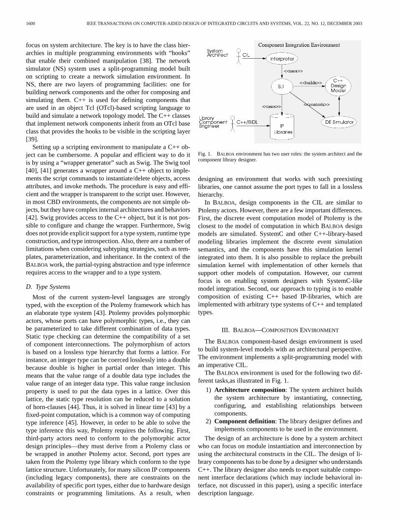
Fig. 1. BALBOA environment has two user roles: the system architect and thecomponent library designer.
designing an environment that works with such preexistinglibraries, one cannot assume the port types to fall in a losslesshierarchy.
In BALBOA, design components in the CIL are similar toPtolemy actors. However, there are a few important differences.First, the discrete event computation model of Ptolemy is theclosest to the model of computation in which BALBOA designmodels are simulated. SystemC and other C++-library-basedmodeling libraries implement the discrete event simulationsemantics, and the components have this simulation kernelintegrated into them. It is also possible to replace the prebuiltsimulation kernel with implementation of other kernels thatsupport other models of computation. However, our currentfocus is on enabling system designers with SystemC-likemodel integration. Second, our approach to typing is to enablecomposition of existing C++ based IP-libraries, which areimplemented with arbitrary type systems of C++ and templatedtypes.
III. B ALBOA—COMPOSITIONENVIRONMENT
The BALBOA component-based design environment is usedto build system-level models with an architectural perspective.The environment implements a split-programming model withan imperative CIL.
The BALBOA environment is used for the following two dif-ferent tasks,as illustrated in Fig. 1.
1) Architecture composition: The system architect buildsthe system architecture by instantiating, connecting,configuring, and establishing relationships betweencomponents.
2) Component definition: The library designer defines andimplements components to be used in the environment.
The design of an architecture is done by a system architectwho can focus on module instantiation and interconnection byusing the architectural constructs in the CIL. The design of li-brary components has to be done by a designer who understandsC++. The library designer also needs to export suitable compo-nent interface declarations (which may include behavioral in-terface, not discussed in this paper), using a specific interfacedescription language.

DOUCETet al.: BALBOA: COMPONENT-BASED DESIGN ENVIRONMENT FOR SYSTEM MODELS 1601
Fig. 2. Layering in the BALBOA environment: the SLI implements the typingabstraction and the type introspection capabilities.
A. Languages and Runtime Layering
In BALBOA, the languages and the runtime environment arelayered. Fig. 2 shows the layers; their descriptions is as follows.
1) The architecture definition layer is where architecturesare built using the CIL. It is an interpreted language basedon OTcl [46] that implements a component model forinstantiations, configurations, and connections. At thislevel, the type of a component is abstracted and a typemanagement system is used to infer and instantiate theexact types required by the simulation model. We refer tothis layer as the interpreted or scripting layer. The CIL isdescribed in detail in Section IV.
2) The component definition layer is the bottom layer,where C++ components are stored in IP libraries. Classesin this layer need not be derived from a specific BALBOA
C++ interface. Ideally, this layer can accommodate anyC++ IP models in a range of libraries without affectingthe implementation of the upper layers. This layer is alsocalled the compiled layer.
3) The intermediate wrapper layer is the link between theinterpreted and the compiled layer. Each CIL componentis shadowed by a C++ compiled object that is containedand manipulated through an SLI wrapper. The SLI is thehook class that implements the reflection and the intro-spection capabilities [47] of the CIL.
Reflection is the capability of the SLI to read or write theattributes, and to invoke the methods of the compiled object.Introspection is the capability of the CIL language to query thereflected information of a component and to understand its ownstructure. The information being reflected and introspectedis specified using the BALBOA interface definition language(BIDL) compiler. This includes the interface types, methodsignatures, as well as behavioral properties which may beusable by the environment for checking compatibility betweencomponents. The BIDL is described in Section IV.
The SLIs implement the type abstraction and inference tokeep the CIL description focused on component instantiations,compositions and connections. Typing abstraction means that
(a) (b) (c)
Fig. 3. How to implement necessary system and environment interfacesin C++: (a) hierarchy and concurrency system semantics in SystemC byinheritance; (b) add OTcl composition and manipulation by using multipleinheritance; and (c) separate system from environment semantics throughdynamic composition.
(a) (b)
Fig. 4. Generic wrapping dependencies and strategies. (a) Strong compile-time inheritance dependency. (b) Weaker runtime composition dependency withintrospection.
it is possible to reduce the type dependencies of the stronglytyped compiled C++ layer, through careful type management atthe wrapper level. The next subsection explains how the usageof an SLI reduces the type dependencies by using delegation.
B. Type Dependencies and Interfaces
The type abstraction in BALBOA is based on a program-ming tradeoff between inheritance and aggregation [35]. Itis common to use inheritance to give design components therequired interface to be manipulated in an environment. InBALBOA, we use aggregation (through the SLIs) because itweakens the type dependencies between a component and itsintegration environment.
Let us use an example to explain this. Consider that, if we de-fine a class namedAdder using the SystemC library, we haveto inherit a class namedsc module that implements the in-terface to the simulation kernel. This is illustrated in Fig. 3(a)with an inheritance relationship. The inheritance dependency isspecified in the class declaration and is resolved and checkedat compile time. When instantiating anAdder to the environ-ment, the object is also asc module because it has both inter-faces. This property of inheritance relationships is genericallyillustrated in Fig. 4(a), where the instance of the wrapper andthe instance of the component are the same. The flipside is thatchanging the interface of the wrapper also changes the inter-face of the component. Now, consider that we want to use thisSystemCAdder in an OTcl environment. For this, it needs toimplement theTclObject interface; therefore, we introducethe second inheritance dependency in Fig. 3(b).
The aggregation alternative is showed in Fig. 4(b). In thiscase, the instances of the wrapper and of the component are twodifferent objects with distinct identities. In the BALBOA envi-ronment, we adopted this strategy. An example is illustrated inFig. 3(c), where anAdder class inherits from the SystemC baseclass for the concurrency and hierarchy semantics, and an SLIinherits from theTclObject class for architecture composi-tion and component assembly semantics. The SLI is the wrapperthat aggregates the component and understands its semantics(that it manipulates a SystemC component).

1602 IEEE TRANSACTIONS ON COMPUTER-AIDED DESIGN OF INTEGRATED CIRCUITS AND SYSTEMS, VOL. 22, NO. 12, DECEMBER 2003
Fig. 5. Runtime environment structure. Each component has a SLI wrapper tointerpret CIL script commands.
Unlike other implementations where a component inherits aclass interface implementing the wrapper behavior, in our en-vironment, the SLI aggregates the design component. It is de-liberately designed to be different from the interface defini-tion and implementation notions in Java. It often happens thattwo components providing the same functionality are imple-mented with different interfaces from different class libraries.However, we may want to use both components in the environ-ment, for instance, if they provide different abstractions. Reuseby class interface precedes the design of the class, while reusewith the composition succeeds the design of the class [35]. Inother words, instead of adapting the IP, it is better to adapt thewrapper.
Note that the SLI wrapper must not be confused with a bus ora protocol wrapper. These are used for translating or adapting aprotocol into another one. In our case, the focus is on the issue ofseparating the semantics of the environment from the semanticsof the design, and to use the SLI for typing and connectivityabstraction. Both are related because connectivity abstractionis indeed a part of the process of communication refinement,which can use bus wrappers.
In this case, the goal is to investigate type abstraction andinteroperability by using object composition instead of classinheritance. The delegation provides a mechanism wherecompositional typing issues can be resolved dynamically andautomatically by the environment (instead of being resolved atcompile-time).
C. More on the Runtime Structure
Fig. 5 shows the relations between the interpreter, the SLIs,and the components at runtime. There are four compiled C++design components: C1, C2, C3, and a compiled discrete eventsimulation kernel component, e.g., SystemC kernel. Every com-ponent has an SLI. Component C2 is composed of componentC3, but the SLIs are not composed. The arrows represent the en-vironment control flow. The full lines are the interpreted controlflow, while the dashed lines are the compiled control flow. Usu-ally, the interpreted control flow will be a set of compositioncommands that will be forwarded to the SLIs. The compiledcontrol flow is usually the execution of the simulation. Notethat the simulation semantics are part of the compiled controlflow, since the simulation kernel interacts directly with com-piled components. The simulation semantics are described inBIDL and loaded into the CIL type system as a set of component
Fig. 6. Internal architecture of a BALBOA component.
types. The dashed lines in Fig. 5 are an illustration of the con-trol flow from the discrete event simulator to the components.Nothing prevents mixing slow interpreted commands with thefast compiled simulation. When simulation speed is not an issue,using the CIL can be very expressive for validation and debug-ging. The CIL provides a number of stimuli generators, moni-tors, and assertion constructs that can be used for validation.
D. Internal Architecture of a Component
In the BALBOA framework, a component refers to all thelayers on the right side of Fig. 2. A CIL component is anOTcl class with methods and attributes that are shadowedby all the compiled objects inside the shaded box in Fig. 6.The SLI manages the type information and implements theintrospective and reflective capabilities. The type system reifiesmeta information, that being the C++ type of the internal designobject (SystemC) and its nonfunctional properties. The typeadapter bridge (TAB) is the only object that provides directaccess to the internal compiled object. The SLI manipulatesthe internal object through the TAB interface. Both the SLI andthe TAB will access the type system information. The SLI canwork with partial type information, while the TAB can onlywork with the exact full type.
As described earlier, a CIL interface for a component can bemapped to many different C++ implementations. For each oneof these possible mappings, a TAB specific to each C++ typewill be created by the BIDL compiler. The type inference willselect the appropriate TAB from a table in the SLI before theallocation of the internal design object.
IV. L ANGUAGES IN BALBOA
In this section, we present the languages used specificallyin BALBOA. IP components are implemented with C++ and, intheory, all C++ classes can be used in the framework. We willdiscuss the two other languages, CIL to assemble system archi-tecture and BIDL to describe component interfaces.
DOUCETet al.: BALBOA: COMPONENT-BASED DESIGN ENVIRONMENT FOR SYSTEM MODELS 1603
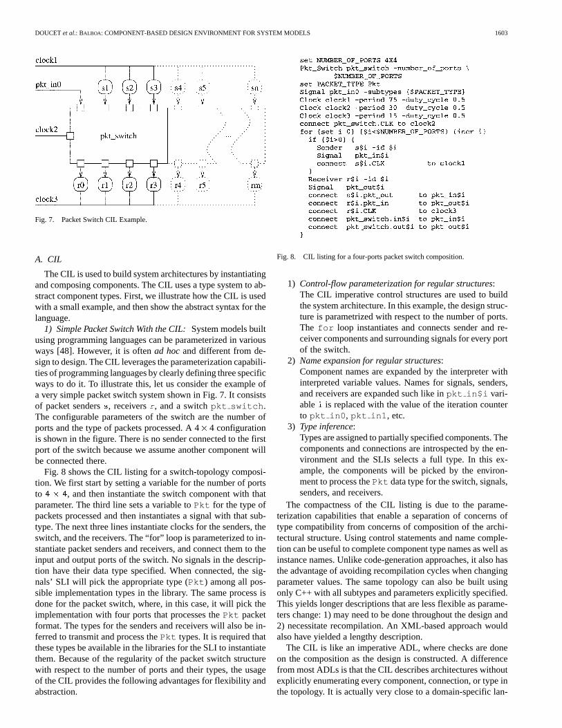
Fig. 7. Packet Switch CIL Example.
A. CIL
The CIL is used to build system architectures by instantiatingand composing components. The CIL uses a type system to ab-stract component types. First, we illustrate how the CIL is usedwith a small example, and then show the abstract syntax for thelanguage.
1) Simple Packet Switch With the CIL:System models builtusing programming languages can be parameterized in variousways [48]. However, it is oftenad hocand different from de-sign to design. The CIL leverages the parameterization capabili-ties of programming languages by clearly defining three specificways to do it. To illustrate this, let us consider the example ofa very simple packet switch system shown in Fig. 7. It consistsof packet senders, receivers , and a switchpkt switch .The configurable parameters of the switch are the number ofports and the type of packets processed. A 44 configurationis shown in the figure. There is no sender connected to the firstport of the switch because we assume another component willbe connected there.
Fig. 8 shows the CIL listing for a switch-topology composi-tion. We first start by setting a variable for the number of portsto , and then instantiate the switch component with thatparameter. The third line sets a variable toPkt for the type ofpackets processed and then instantiates a signal with that sub-type. The next three lines instantiate clocks for the senders, theswitch, and the receivers. The “for” loop is parameterized to in-stantiate packet senders and receivers, and connect them to theinput and output ports of the switch. No signals in the descrip-tion have their data type specified. When connected, the sig-nals’ SLI will pick the appropriate type (Pkt ) among all pos-sible implementation types in the library. The same process isdone for the packet switch, where, in this case, it will pick theimplementation with four ports that processes thePkt packetformat. The types for the senders and receivers will also be in-ferred to transmit and process thePkt types. It is required thatthese types be available in the libraries for the SLI to instantiatethem. Because of the regularity of the packet switch structurewith respect to the number of ports and their types, the usageof the CIL provides the following advantages for flexibility andabstraction.
Fig. 8. CIL listing for a four-ports packet switch composition.
1) Control-flow parameterization for regular structures:The CIL imperative control structures are used to buildthe system architecture. In this example, the design struc-ture is parametrized with respect to the number of ports.The for loop instantiates and connects sender and re-ceiver components and surrounding signals for every portof the switch.
2) Name expansion for regular structures:Component names are expanded by the interpreter withinterpreted variable values. Names for signals, senders,and receivers are expanded such like inpkt in$i vari-able is replaced with the value of the iteration counterto pkt in0 , pkt in1 , etc.
3) Type inference:Types are assigned to partially specified components. Thecomponents and connections are introspected by the en-vironment and the SLIs selects a full type. In this ex-ample, the components will be picked by the environ-ment to process thePkt data type for the switch, signals,senders, and receivers.
The compactness of the CIL listing is due to the parame-terization capabilities that enable a separation of concerns oftype compatibility from concerns of composition of the archi-tectural structure. Using control statements and name comple-tion can be useful to complete component type names as well asinstance names. Unlike code-generation approaches, it also hasthe advantage of avoiding recompilation cycles when changingparameter values. The same topology can also be built usingonly C++ with all subtypes and parameters explicitly specified.This yields longer descriptions that are less flexible as parame-ters change: 1) may need to be done throughout the design and2) necessitate recompilation. An XML-based approach wouldalso have yielded a lengthy description.
The CIL is like an imperative ADL, where checks are doneon the composition as the design is constructed. A differencefrom most ADLs is that the CIL describes architectures withoutexplicitly enumerating every component, connection, or type inthe topology. It is actually very close to a domain-specific lan-
1604 IEEE TRANSACTIONS ON COMPUTER-AIDED DESIGN OF INTEGRATED CIRCUITS AND SYSTEMS, VOL. 22, NO. 12, DECEMBER 2003
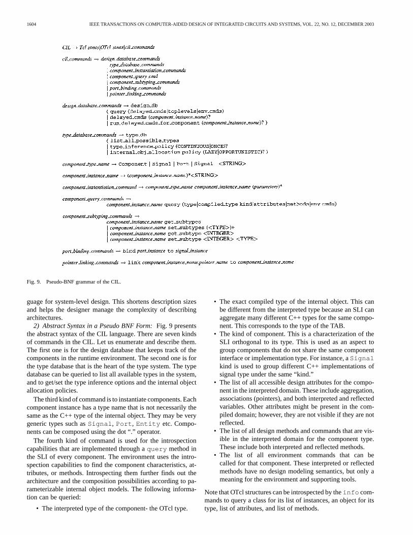
Fig. 9. Pseudo-BNF grammar of the CIL.
guage for system-level design. This shortens description sizesand helps the designer manage the complexity of describingarchitectures.
2) Abstract Syntax in a Pseudo BNF Form:Fig. 9 presentsthe abstract syntax of the CIL language. There are seven kindsof commands in the CIL. Let us enumerate and describe them.The first one is for the design database that keeps track of thecomponents in the runtime environment. The second one is forthe type database that is the heart of the type system. The typedatabase can be queried to list all available types in the system,and to get/set the type inference options and the internal objectallocation policies.
The third kind of command is to instantiate components. Eachcomponent instance has a type name that is not necessarily thesame as the C++ type of the internal object. They may be verygeneric types such asSignal , Port , Entity etc. Compo-nents can be composed using the dot “.” operator.
The fourth kind of command is used for the introspectioncapabilities that are implemented through aquery method inthe SLI of every component. The environment uses the intro-spection capabilities to find the component characteristics, at-tributes, or methods. Introspecting them further finds out thearchitecture and the composition possibilities according to pa-rameterizable internal object models. The following informa-tion can be queried:
• The interpreted type of the component- the OTcl type.
• The exact compiled type of the internal object. This canbe different from the interpreted type because an SLI canaggregate many different C++ types for the same compo-nent. This corresponds to the type of the TAB.
• The kind of component. This is a characterization of theSLI orthogonal to its type. This is used as an aspect togroup components that do not share the same componentinterface or implementation type. For instance, aSignalkind is used to group different C++ implementations ofsignal type under the same “kind.”
• The list of all accessible design attributes for the compo-nent in the interpreted domain. These include aggregation,associations (pointers), and both interpreted and reflectedvariables. Other attributes might be present in the com-piled domain; however, they are not visible if they are notreflected.
• The list of all design methods and commands that are vis-ible in the interpreted domain for the component type.These include both interpreted and reflected methods.
• The list of all environment commands that can becalled for that component. These interpreted or reflectedmethods have no design modeling semantics, but only ameaning for the environment and supporting tools.
Note that OTcl structures can be introspected by theinfo com-mands to query a class for its list of instances, an object for itstype, list of attributes, and list of methods.

DOUCETet al.: BALBOA: COMPONENT-BASED DESIGN ENVIRONMENT FOR SYSTEM MODELS 1605
Fig. 10. Pseudo-BNF for an abstract syntax of the BIDL.
The fifth kind of commands is for subtyping. Type parame-ters is what enables partial typing in the CIL. For example, aPort type can be subtyped with abool parameter. When allparameters are set, the CIL-to-C++ mapping can be done andvalidated. Note that “subtyping” here means parameterization.In CIL, it is possible to list and set all subtypes parameters fora component.
The sixth and seventh kind of commands in the CIL are to es-tablish connections. Ports and signals can be bound and pointerscan be linked to objects by thebind andlink procedures, re-spectively. When using connection commands at the interpretedlayer, type management is done by the SLIs. For example, whena pointer is set to a component through thelink to method,the runtime environment checks that the target component is ofthe right type for the association. For ports, the runtime envi-ronment will make sure that the transmitted data types are thesame.
B. BIDL
The BIDL is used to describe the interfaces, type, subtypes,parameters, and characteristics of the internal object, and to “ex-port it” to the interpreted domain. The BIDL compiler gener-ates C++ code to create and configure the SLI and type adaptersbridges. The BIDL was first inspired by the CORBA IDL [49]and has been extended and customized for the requirements ofsystem-level modeling. The BIDL was developed incrementallyas keywords were added to C++ class declarations. For example,the component designer can copy the header of a class into aBIDL description, remove the parts that should be hidden fromthe interpreted domain and add keywords for subtyping, kindand available instantiatable subtypes information. The BIDLcompiler translates and expands the description of componenttypes to a format that the interpreter can understand. The BIDLhas a role similar to the CPP preprocessor. Instead of macro
expansions, it generates a custom type system extension, spe-cific to every component type. These extensions are generatedin C++, compiled, and placed into IP component libraries. Asthe type theory is developed, the BIDL syntax evolves as well,but this will be discussed in a future paper.
Fig. 10 shows the abstract grammar of the BIDL language.Component declarations can be done either in C++ or by usinga neutral on the component definition language, such as theCORBA IDL. Kind, subtypes, attributes, methods, and classmappings are declared in the BIDL.
V. TYPE RESOLUTION IN BALBOA
A. Simple Parameterization Example: Fast Fourier Transform(FFT)
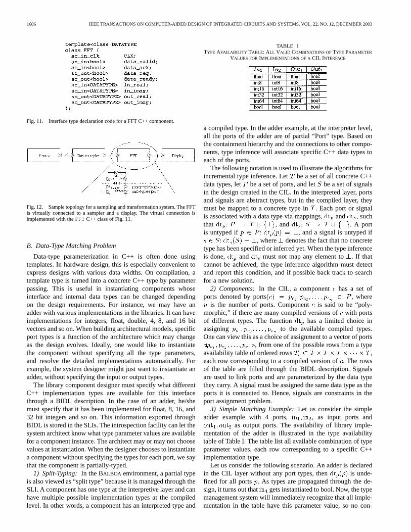
Fig. 11 shows the C++ code for an FFT-class interface, withthe real and imaginary inputs and outputs ports, and a typeparameter for the data widths. Fig. 12 shows a diagram of asampling system using this FFT module. The connections be-tween components are abstract, meaning that the user does nothave to specify their types. In the BALBOA environment, a de-signer can query the libraries for available FFT implementationtypes and choose one. The type inference will propagate thechosen parameter to all components that are connected to theFFT. However, these other components need to have implemen-tations for the chosen type parameter. If not, the type propaga-tion will backtrack and request another different starting param-eter. For instance, the downsampler may not have an implemen-tation available in the library for a specific data width used asinput to the FFT. In this example, backtracking is not difficult,but as the design grows in size, it is better that the system auto-matically handles this type propagation. In this section, we willexplain how the CIL uses the type system to abstract C++ im-plementation types. We first consider small examples and thendevelop the type theory along the data type interface dimension.
1606 IEEE TRANSACTIONS ON COMPUTER-AIDED DESIGN OF INTEGRATED CIRCUITS AND SYSTEMS, VOL. 22, NO. 12, DECEMBER 2003
Fig. 11. Interface type declaration code for a FFT C++ component.
Fig. 12. Sample topology for a sampling and transformation system. The FFTis virtually connected to a sampler and a display. The virtual connection isimplemented with theFFT C++ class of Fig. 11.
B. Data-Type Matching Problem
Data-type parameterization in C++ is often done usingtemplates. In hardware design, this is especially convenient toexpress designs with various data widths. On compilation, atemplate type is turned into a concrete C++ type by parameterpassing. This is useful in instantiating components whoseinterface and internal data types can be changed dependingon the design requirements. For instance, we may have anadder with various implementations in the libraries. It can haveimplementations for integers, float, double, 4, 8, and 16 bitvectors and so on. When building architectural models, specificport types is a function of the architecture which may changeas the design evolves. Ideally, one would like to instantiatethe component without specifying all the type parameters,and resolve the detailed implementations automatically. Forexample, the system designer might just want to instantiate anadder, without specifying the input or output types.
The library component designer must specify what differentC++ implementation types are available for this interfacethrough a BIDL description. In the case of an adder, he/shemust specify that it has been implemented for float, 8, 16, and32 bit integers and so on. This information exported throughBIDL is stored in the SLIs. The introspection facility can let thesystem architect know what type parameter values are availablefor a component instance. The architect may or may not choosevalues at instantiation. When the designer chooses to instantiatea component without specifying the types for each port, we saythat the component is partially-typed.
1) Split-Typing: In the BALBOA environment, a partial typeis also viewed as “split type” because it is managed through theSLI. A component has one type at the interpretive layer and canhave multiple possible implementation types at the compiledlevel. In other words, a component has an interpreted type and
TABLE ITYPE AVAILABILITY TABLE: ALL VALID COMBINATIONS OF TYPE PARAMETER
VALUES FORIMPLEMENTATIONS OF A CIL INTERFACE
a compiled type. In the adder example, at the interpreter level,all the ports of the adder are of partial “Port” type. Based onthe containment hierarchy and the connections to other compo-nents, type inference will associate specific C++ data types toeach of the ports.
The following notation is used to illustrate the algorithms forincremental type inference. Let be a set of all concrete C++data types, let be a set of ports, and let be a set of signalsin the design created in the CIL. In the interpreted layer, portsand signals are abstract types, but in the compiled layer, theymust be mapped to a concrete type in. Each port or signalis associated with a data type via mappings, and , suchthat , and . A portis untyped if , and a signal is untyped if
, where denotes the fact that no concretetype has been specified or inferred yet. When the type inferenceis done, and must not map any element to. If thatcannot be achieved, the type-inference algorithm must detectand report this condition, and if possible back track to searchfor a new solution.
2) Components:In the CIL, a component has a set ofports denoted by ports , where
is the number of ports. Componentis said to be “poly-morphic,” if there are many compiled versions ofwith portsof different types. The function has a limited choice inassigning to the available compiled types.One can view this as a choice of assignment to a vector of ports
, from one of the possible rows from a typeavailability table of ordered rows ,each row corresponding to a compiled version of. The rowsof the table are filled through the BIDL description. Signalsare used to link ports and are parameterized by the data typethey carry. A signal must be assigned the same data type as theports it is connected to. Hence, signals are constraints in theport assignment problem.
3) Simple Matching Example:Let us consider the simpleadder example with 4 ports, , as input ports and
as output ports. The availability of library imple-mentation of the adder is illustrated in the type availabilitytable of Table I. The table list all available combination of typeparameter values, each row corresponding to a specific C++implementation type.
Let us consider the following scenario. An adder is declaredin the CIL layer without any port types, then is unde-fined for all ports . As types are propagated through the de-sign, it turns out that gets instantiated to bool. Now, the typemanagement system will immediately recognize that all imple-mentation in the table have this parameter value, so no con-

DOUCETet al.: BALBOA: COMPONENT-BASED DESIGN ENVIRONMENT FOR SYSTEM MODELS 1607
clusion is available. Let us assume next that gets typed to. The SLI can now match the row:
. Then, it will be inferred that andshould also be of type . At this point, any signal that is
connected to and will have the type propagated to themas . This means that ,and .
C. Formulation of the BALBOAType Inference Problem
Given a design with a set of ports, a set of signals, andthe partition of into disjoint sets, where is the numberof components and the partition of is disjoint because, ascomponents do not share ports, the type inference problemis as follows. For each component, with its port vector
, assign a row from its type availability table, such that if there is a signal , which connects a portin component to another port of a component , then
the type assigned to and to must be the same. Thisrestriction makes the problem complex, and we show here thatthe problem is NP complete.
Theorem 5.1:The BALBOA type inference problem is NPComplete.
Proof: Given a type assignment for all the ports, it is easyto check in polynomial time that the assignments in the typetables are correct, and the ports connected via signals have thesame type. Hence, the problem is clearly in NP.
For the NP-hardness proof, we reduce the problem ofone-in-three monotone 3SAT [50], to the BALBOA type-infer-ence problem. 3SAT is the following problem. Given a setof Boolean variables and a collection of disjunctive clausesover , such that each clause is a disjunction of exactly threeliterals, find if there is a truth assignment of the variables in,such that all of the clauses are satisfied. One-in-three 3SAT, isa special case of 3SAT problem, where the truth assignment of
has the restriction that if and are two literals appearingin the same clause, then both cannot be assigned the truth valueof one. Monotone one-in-three 3SAT, has the further restrictionthat no negated literal appears in any of the clauses.
Given an instance of monotone one-in-three 3SAT, for eachclause , which has three literals , one can create atable , with exactly three rows .Given the set of vector of variables in , one hasto assign one of the rows in tablewith the restriction that if thevariable that appears as in also appears in another clauseas , then the choice of the rows from and must be suchthat the assigned truth values are the same forand . Thisis a version of the BALBOA type-inference problem and, hence,it is at least as hard as the monotone one-in-three 3SAT, whichis known to be NP complete [50].
Given that the problem is NP complete, we use heuristics tosolve the problem. Moreover, the problem is solved incremen-tally because components are added or deleted in the CIL—thetype assignments keep changing. The heuristic implemented inthe BALBOA type-inference uses a delaying mechanism whichdelays the type instantiation and allocation of components untilall type parameters associated with a component are resolved.The resolution is done on-the-fly, as components are added, typeparameters get propagated to partial types.
D. Heuristics for BALBOAType Inference
There are multiple ways of solving these problems, includingdynamic programming, local search [51], etc. A sequence ofnatural join operations may take a long time, since the different
s have different sizes. The order in which the joins are com-puted can be optimized using dynamic programming; hence, wewill follow that approach. However, since we build models in-crementally, when a new component is added and connected, thenew required join may not be in the order that the dynamic pro-gramming would have yielded. In the current implementationof the BALBOA environment, the runtime type inference mech-anism may be summarized as follows. We first verify compat-ibility of types when connections are set between two compo-nents. We join the type availability tables of both components,renaming the connected ports to the same name if necessary. Ifthe join returns empty, the components are not compatible; ifit is not empty, the system will remember the result. Since theSLI allocates the component, it can decide to delay the alloca-tion until the type parameterization is resolved. Now, consid-ering this join result as the type availability table for this pair ofcomponents, we then select a new component that is connectedto one of these, and apply the procedure.
If the result of the final join is empty, the architecture de-scribed in the CIL cannot be instantiated with the available im-plementations. If it is singleton, then we have found a uniquecombination of type parameters that can be instantiated. If thefinal join yields multiple rows, we have to choose a type param-eter combination from the final table.
Fig. 13 shows a simplified version of the type-inferenceheuristic. TheCheckTypingheuristic chooses two componentsthat are connected, both with small type availability table sizes.It does a join locally between the two components to assessthat the types are compatible. While the designer is usingthe CIL, this join is used to propagate type parameters as thearchitecture is built. All connection information is passed to thejoin procedure as , which is used to decide which columnsof the tables to run the join on.
In the current implementation, the runtime environment doesnot build the join tables explicitly, but walks the architecturalgraph and builds the join tables implicitly in the SLIs. In thiscase, the runtime environment does an incremental version ofthis procedure by remembering all the intermediate join resultsthrough the SLIs. In future works, we will study optimizations ofthis procedure, including caching joins, incremental joins, etc.
VI. I MPLEMENTATION AND RESULTS
This section shows the usage of the CIL for a moderatelycomplex real design example. The AMRM is an adaptive cachememory system [11] that can have its configuration changed dy-namically. For instance, associativity and line size can be con-figured by special processor instructions. The hardware part ofthe design is a regular cache subsystem with a modified con-troller for cache adaptation.
Fig. 14 shows the outline of the procedure we followed forcomponent integration and communication refinement. At eachstep, we refined both the component and the connector, but we

1608 IEEE TRANSACTIONS ON COMPUTER-AIDED DESIGN OF INTEGRATED CIRCUITS AND SYSTEMS, VOL. 22, NO. 12, DECEMBER 2003
Fig. 13. Simplified type inference heuristics implemented in the BALBOA runtime environment.
Fig. 14. AMRM models in different levels of abstraction for the componentsand connectors.
encapsulated the changes behind a CIL interface. Each box rep-resents a memory hierarchy level, encapsulating the controllerand the memory array, and the line between the two boxes repre-sents a connection between the levels. At the top most level, weassume that there is a connection between the memory levels butthere are no assumptions on its type or implementation. Com-munication refinement yields several versions of the componentand the connector. Fig. 15 shows both the UML class diagramsand the block diagrams for the component integration and thecommunication refinements.
The script listed in Fig. 16 shows the CIL file used at all re-finement levels: we start by instantiating two cache componentsnamedL1 andL2 , and a memory component namedMem. Thelast lines invoke method calls to the interface of the componentsto establish the connections. These methods are reimplementedas the abstract connection is refined.
A. First Refinement
In the first refinement, the connector is a pointer referring tothe lower level of memory hierarchy. Method invocations along
this pointer implement message passing in a sequential model.In the class diagram of Fig. 15(a),Memory Base is the baseclass for theCache andMemory classes. TheMemory Basehasread andwrite virtual methods that are implemented intheCache andMemory classes to implement the componentbehaviors. TheCache class has an association (pointer) namedlower memory that is used to navigate to the lower level ofmemory. For example, on an L1 cache read miss, the L1 cachewill use this association to call read method of L2 cache. Theblock diagram in Fig. 15(d) shows how theselower memoryassociations implement the control flow between the two levelsof cache and the main memory. The procedure listed in Fig. 17sets the association pointers between two caches. It is an OTclmethod of theCache Ctrl component that sets its ownpointer (by$self ) to the lower memory level.
B. Second Refinement
In the second refinement, we change the pointer for twoqueues: one for the requests and one for the answers. The classdiagram on Fig. 15(b) illustrates this change. The refinementalso introduces concurrency with the addition of a reactiveprocess namedproc to the Cache and Memory classes.These processes are triggered by events onclock input portsand transitively call theread() andwrite() methods. Thescript on Fig. 18 lists the procedure to connect two cachestogether with queues as link objects. The first lines instantiatethe queues. The data types of the queues will be set accordingto the types of the association pointers to which they areconnected. The other lines establish the associations betweenthe caches and the queues. Fig. 15(e) shows the architecturalview, where each cache level is separated by two queues.

DOUCETet al.: BALBOA: COMPONENT-BASED DESIGN ENVIRONMENT FOR SYSTEM MODELS 1609
Fig. 15. AMRM component integration models with communication refinement: the upper row is for the class diagrams, and the lower row is for the correspondingblock diagrams: (a) and (d) pointer connectors, (b) and (e) queue connectors, and (c) and (f) signal connectors.
Fig. 16. Top-level architecture file for the AMRM structure.
Fig. 17. Connection procedure.
Fig. 18. Refined connection procedure.
C. Third Refinement
The lowest level of abstraction in our AMRM models usessignal communications. Fig. 15(c) shows the class diagram forthis model. The behaviors of the queues are still in the design,but is refined through ports beginning by “l” for the lowermemory, and by “u” for the upper memory. These ports arebound to theMemBus link class, which encapsulates all signalobjects. Fig. 15(f) shows the block diagram with the memoryhierarchy and the buses. The script in Fig. 19 lists the procedureto connect two caches through a bus. We now use thebindcommand for the port object instead of thelink command forpointers. The third line instantiates a cache bus namedcb . Theremainder of the listing individually connect the ports of theupper and the lower cache to the bus signals.
D. Code Generation Ratios and Discussion
Table II shows the design statistics of the file sizes and code-generation ratios for the various AMRM implementations. Aswe refine the models, the script sizes grow larger, but not thenumber of C++ classes (except for the queue data type class inthe second refinement). This is because the granularity of thecommunications gets smaller and there are more connections tobe established.

1610 IEEE TRANSACTIONS ON COMPUTER-AIDED DESIGN OF INTEGRATED CIRCUITS AND SYSTEMS, VOL. 22, NO. 12, DECEMBER 2003
Fig. 19. Refinement with signal connectors.
TABLE IIDESIGN STATISTICS OF AMRM M ODELS: CODE GENERATION
RATIO AT HIGHER ABSTRACTIONS
The programming efforts to write BIDL files in the exper-imentations were nonintrusive and of low effort. We used theparts of the header of the classes we wanted visible to the in-terpreter and we added characterizations as behavioral or struc-tural components. The ratio of the IP versus generated code sizesshown is increasing as the abstraction is lowered. However, thesize of the BIDL file and the generated code does not grow lin-early with the size of the IP code. The environment does nottake design decisions for the designer in the communication re-finement, except for the type propagation. Work is in progressto investigate what ratios of code generation are obtained in dif-ferent design contexts, and to minimize the size of the SLIs.
The CIL provides a high-level view focused on the compo-nents and the connectors. Parameterization with control flow,name concatenation, and type inference parameterization withno recompilation are definite advantages over using only C++.The AMRM design example shows a refinement using the com-ponent modeling capabilities of the CIL extended with connec-tion-method customizations. A future enhancement will be toisolate the connector from the connection method, so that thetype inference can choose a connector according to the set ofcommunication patterns.
VII. CLOSING REMARKS AND FUTURE WORK
Component composition frameworks represent an excitingdevelopment in the area of high-level modeling for system-leveldesign. A successful adoption of those frameworks is likelyto have a direct impact on the successful management ofcomplexity of the new generations of SOC designs. However,
there are several technical challenges that must be overcome.The chief among them are ensuring inherent composabilityand reuse of SOC components. The problem extends beyondlarge scale program constructions in software engineering,where several advances in architectural modeling and designenvironments have occurred. The challenge is due to thediversity of the computation models, levels of abstractionsused, and the notion of correctness applicable to SOC com-ponents. Advances in the understanding of cosimulation andmodels of computation are important aspects of the problemthat have been addressed well. Challenges remain in aspectsrelated to encapsulation and reusability of components. TheBALBOA framework addresses this aspect of the problem bydeconstructing the task of component creation from componentcomposition. Our approach is a bottom-up approach of SOCconstruction using reusable IP. The underlying programmingand automatic wrapper generation capabilities are built uponsoftware engineering techniques, namely, reflection and intro-spection of the components and composition by delegation.The focus of our ongoing effort is to understand and developtechniques to raise the level of abstraction used in interfacecomposition and exploit to the system-level verification oppor-tunities present in such an approach. For example, in the typeinference arena, the data-type matching is just a starting point.Currently, a behavioral type system is being developed to checkthe functional validity of composition of virtual components.
ACKNOWLEDGMENT
The authors would like to thank the anonymous reviewersfor their constructive comments and suggestions. The authorswould also like to thank J.-P. Talpin, R. Jerjurikar, C. Pereira,and S. Tauro for their technical feedback, help, and suggestions.
REFERENCES
[1] Semiconductor Industry Association, International TechnologyRoadmap for Semiconductors (2001). [Online]. Available: http://public.itrs.net/.
[2] R. K. Gupta and S. Y. Liao, “Using a programming language for digitalsystem design,”IEEE Design and Test of Comput., pp. 72–80, Apr.–June1997.
[3] S. Liao, S. Tjiang, and R. Gupta, “An efficient implementation of reac-tivity in modeling hardware in the scenic synthesis and simulation en-vironment,” in Proc. IEEE/ACM Design Automation Conf., 1997, pp.70–75.
[4] OSCI, SystemC [Online]. Available: http://www.systemc.org.[5] D. Gajski, J. Zhu, R. Domer, A. Gerstlauer, and S. Zhao,SpecC: Speci-
fication Language and Methodology. Norwell, MA: Kluwer, 2000.[6] P. Schaumont, S. Vernalde, L. Rijnders, M. Engels, and I. Bolsens,
“A programming environment for the design of complex high-speedASICs,” in Proc. IEEE/ACM Design Automation Conf., 1998, pp.315–320.
[7] L. Semeria and A. Ghosh, “Methodology for hardware/software co-ver-ification in C/C++,” in Proc. High-Level Design Validation and TestWorkshop, 1999, pp. 67–72.
[8] G. D. Michelli, “Hardware synthesis from C/C++ models,” inProc. De-sign Automation and Test Eur. Conf., 1999, p. 80.
[9] C. Weiler, U. Kebschull, and W. Rosenstiel, “C++ base classes for spec-ification, simulation, and partitioning of a hardware/software system,”in Proc. CS Workshop on VLSI, 1995, pp. 777–784.
[10] R. Roth and D. Ramanathan, “A high-level hardware design method-ology using C++,” inProc. High-Level Design Validation and Test Work-shop, 1999, pp. 73–80.
[11] AMRM, Adaptive Memory Platform (2000) [Online]. Available:http://www. cecs.uci.edu/~amrm.

DOUCETet al.: BALBOA: COMPONENT-BASED DESIGN ENVIRONMENT FOR SYSTEM MODELS 1611
[12] M. D. McIlroy, “Mass produced software components,” inSoftwareEng.: Rep. Conf. Sponsored by NATO Sci. Committ., Oct. 1968, pp.138–155.
[13] J. Hopkins, “Component primer,”Commun. ACM, pp. 27–30, Oct. 2000.[14] D. E. Perry and A. L. Wolf, “Foundations for the study of software ar-
chitecture,”ACM Software Eng. Notes, vol. 17, no. 4, pp. 40–52, 1992.[15] F. Doucet, R. Gupta, M. Otsuka, P. Schaumont, and S. Shukla, “Inter-
operability as a design issue in C++-based modeling environments,” inProc. Int. Symp. Syst. Synthesis, 2001, pp. 87–92.
[16] D. Verkest, J. Cockx, F. Potargent, G. Jong, and H. D. Man, “On the useof C++ for system-on-chip design,” inProc. CS Workshop on VLSI, Apr.1999, pp. 42–47.
[17] S. Vernalde, P. Schaumont, and I. Bolsens, “An object oriented program-ming approach for hardware design,” inProc. CS Workshop on VLSI,Apr. 1999, pp. 68–75.
[18] K. Wakabayashi and T. Okamoto, “C-based SoC design flow and EDAtools: An ASIC and system vendor perspective,”IEEE Trans. Computer-Aided Design, vol. 19, pp. 1507–1522, Dec. 2000.
[19] J. Zhu, “MetaRTL: Raising the abstraction level of RTL design,” inProc.Design Automation and Test Eur. Conf., 2001, pp. 71–76.
[20] W. Cesario, A. Baghdadi, L. Gauthier, D. Lyonnard, G. Nicolescu, Y.Paviot, S. Yoo, A. A. Jerraya, and M. Diaz-Nava, “Component-based de-sign approach for multicore SOCs,”Proc. IEEE/ACM Design Automa-tion Conf., pp. 789–794, 2002.
[21] R. A. Bergamaschi, S. Bhattacharya, R. Wagner, C. Fellenz, M. Muh-lada, F. White, W. R. Lee, and J.-M. Daveau, “Automating the designof SOCs using cores,”IEEE Design Test, vol. 18, pp. 32–45, Sept.–Oct.2001.
[22] A. Sangiovanni-Vicentelli and G. Martin, “Platform-based design andsoftware design methodology for embedded systems,”IEEE Design andTest of Comput., vol. 18, pp. 23–33, Dec. 2001.
[23] The Ptolemy 2 Project, Univ. California, Berkeley [Online]. Available:http://ptolemy.eecs.berkeley.edu/.
[24] E. A. Lee and A. Sangiovanni-Vincentelli, “A framework for comparingmodels of computation,”IEEE Trans. Computer-Aided Design, vol. 17,pp. 1217–1229, Dec. 1998.
[25] E. A. Lee and Y. Xiong, “System-level types for component-based de-sign,” inProc. 1st Int. Workshop on Embedded Software, vol. 2211, Oct.2001, pp. 237–253.
[26] V. Sinha, F. Doucet, C. Siska, R. Gupta, S. Liao, and A. Ghosh, “YAML:A tool for hardware design visualization and capture,” inProc. Int. Symp.Syst. Synthesis, 2000, pp. 9–14.
[27] N. Medvidovic and R. N. Taylor, “A classification and comparisonframework for software architecture description languages,”IEEETrans. Software Eng., vol. 26, pp. 70–93, Jan. 2000.
[28] D. Garlan, R. Allen, and J. Ockerbloom, “Architectural mismatch: Whyreuse is so hard,”IEEE Software, vol. 12, pp. 17–26, Nov. 1995.
[29] H. Tomiyama, A. Halambi, P. Grun, N. Dutt, and A. Nicolau, “Archi-tecture description languages for system-on-chip design,” inProc. AsiaPacific Conf. Chip Design Lang., 1999, pp. 109–116.
[30] A. Halambi, P. Grun, V. Ganesh, A. Khare, N. Dutt, and A. Nicolau,“EXPRESSION: A language for architecture exploration through com-piler/simulator retargetability,” inProc. Design Automation and TestEur. Conf., 1999, p. 100.
[31] D. C. Luckham, J. J. Kenney, L. M. Augustin, J. Vera, D. Bryan, and W.Mann, “Specification and analysis of system architecture using rapide,”IEEE Trans. Software Eng., vol. 21, pp. 336–354, Apr. 1995.
[32] T. A. Henzinger, B. Horowitz, and C. M. Kirsch, “Giotto: A time-trig-gered language for embedded programming,” inProc. 1st Int. Workshopon Embedded Software, vol. 2211, Oct. 2001, pp. 166–184.
[33] T. Genssler, O. Nierstrasz, and B. Schoenhage, “Components for em-bedded software: The Pecos approach,” inProc. Int. Conf. Compilers,Architecture, and Systhesis for Embedded Syst., 2002, pp. 19–26.
[34] M. M. Gorlick and A. R. R. Razouk, “Using weaves for software con-struction and analysis,” inProc. Int. Conf. Software Eng., 1991, pp.23–34.
[35] C. Szyperski,Component Software: Beyond Object Oriented Pro-gramm.. Reading, MA: Addison-Wesley, 1998.
[36] E. A. Lee and S. Neuendorffer, “MoML—A Modeling MarkupLanguage in XML,” Univ. California, Berkeley, Tech. Rep. UCB/ERLM00/12, Mar. 2000.
[37] J. K. Ousterhout, “Scripting: Higher-level programming for the 21stCentury,”IEEE Computer, vol. 31, pp. 23–30, Mar. 1998.
[38] L. Breslau, D. Estrin, K. Fall, J. Heidemann, A. Helmy, P. Huang, S.McCanne, K. Varadhan, Y. Xu, and H. Yu, “Advances in network simu-lation,” IEEE Computer, vol. 33, pp. 59–67, May 2000.
[39] NS: The Network Simulator [Online]. Available: http://www.isi.edu/nsnam/ns.
[40] Simplified Wrapper and Interface Generator (SWIG) [Online]. Avail-able: http://www.swig.org.
[41] P. Chen, D. A. Kirkpatrick, and K. Keutzer. Fast integration ofEDA tools and scripting language. presented at Proc. IEEE/DATCElectron. Design Process. Workshop. [Online] Available: http://www.eda.org/edps/edp01/PAPERS/pinhong.pdf.
[42] N. Medvidovic, P. Oreizy, J. E. Robbins, and R. N. Taylor, “Using ob-ject-oriented typing to support architectural design in the C2 style,” inProc. 4th ACM SIGSOFT Symp. Foundations of Software Eng., 1996,pp. 24–32.
[43] Y. Xiong and E. A. Lee, “An extensible type system for component-based design,” inProc. 6th Int. Conf. Tools and Algorithms for the Con-struction and Anal. Syst., vol. 1785, Apr. 2000, pp. 20–37.
[44] J. Rehof and T. Mogensen, “Tractable constraints in finite semilattices,”in Proc. 3rd Int. Static Anal. Symp., vol. 1145, Sept. 1996, pp. 285–300.
[45] B. C. Pierce,Types and Programming Languages. Cambridge, MA:MIT Press, 2002.
[46] D. Wetherall and C. J. Lindblad. Extending Tcl for dynamic object-oriented programming. presented at Proc. Tcl/Tk Workshop. [Online]Available: http://tns-www.lcs.mit.edu/publications/tcltk95.djw.html.
[47] F. Buschmann, R. Meunier, H. Rohnert, P. Sommerlad, and M. Stal,Pat-tern Oriented Software Architecture: A System of Patterns. New York:Wiley, 1996.
[48] T. Groetker, S. Liao, G. Martin, and S. Swan,System Design with Sys-temC. Norwell, MA: Kluwer, 2002.
[49] Corba middleware software, Object Management Group, Inc. [Online].Available: http://www.corba.org.
[50] M. R. Garey and D. S. Johnson,Computers and Intractability: A Guideto the Theory of NP-Completeness. San Francisco, CA: Freeman,1979.
[51] J. D. Ullman,Principles of Database and Knowledge-Base Systems: VolI and II. Rockville, MD: Computer Science, 1989.
Frederic Doucet(S’98) received the B. Eng. degreein computer engineering from Ecole Polytechniquede Montreal, Montreal, PQ, Canada, in 1999 and theM.S. degree in computer science from the Universityof California, Irvine, in 2002. He is currently pur-suing the Ph.D. degree in computer engineering at theUniversity of California at San Diego, La Jolla.
During his studies, he interned with LockheedMartin, the Intel Corporation, and ConexantSystems, Inc. He is a Graduate Fellow of theSemiconductor Research Corporation and a Ph.D.
scholar of the Fond de Recherche sur la Nature et les Technologie of theProvince of Quebec. His research interests are in computer-aided design forsystem-level design, embedded system design, design automation and softwareengineering, and management science.
Mr. Doucet is a student member of the ACM.
Sandeep Shukla(M’01–SM’03) received the B.E.degree in computer science and engineering from Ja-davpur University, Calcutta, India, in 1991 and theM.S. and Ph.D. degrees in computer science from theState University of New York, Albany, in 1995 and1997, respectively.
He was a Principal Member of the technical staff ofGTE Laboratories (now Verizon) from 1997 to 1999.He was a Senior Formal Verification Engineer and,later, a Staff Component Design Engineer with theIntel Corporation from 1999 to 2001. Prior to joining
the Bradley Department of Electrical and Computer Engineering, Virginia Poly-technic Institute and State University in Fall 2002 as an Assistant Professor, hewas on the research faculty at the Center for Embedded Computer Systems,University of California, Irvine. Recently, he established the research labora-tory Formal Engineering Research with Models, Abstraction, and Transforma-tion (FERMAT) at Virginia Tech to carry out research in applications of formalmethods in embedded systems engineering. He has been extensively publishedin the areas of formal verification, hardware/software co-design, and formalmethods for power management.
Prof. Shukla is a recipient of the NSF CAREER Award in 2002. He hasco-edited special issues of theJournal of Circuits, Systems and Computers,and co-chaired the ACM/IEEE Conference on Formal Models and Methods forCo-Design in 2003. He is a Member of the ACM and Sigma Xi.
1612 IEEE TRANSACTIONS ON COMPUTER-AIDED DESIGN OF INTEGRATED CIRCUITS AND SYSTEMS, VOL. 22, NO. 12, DECEMBER 2003
Masato Otsuka received the B.E. degree andthe M.E. degree in information engineering fromNagoya University, Nagoya, Japan, in 1994 and1996, respectively.
He has been a Member of Technical Staff withFujitsu Ltd. since 1996. He has also been a Memberof the System Level Design Study Group of JEITA(formerly EIAJ) since 1998. He was a VisitingResearcher at the University of California, Irvine,from 2000 to 2001. His research interests includehigh-level system design methodologies, models of
computation and communication, and interface specification and verificationtechniques.
Rajesh Gupta (S’83–M’85–SM’97) received theB.Tech. degree in electrical engineering from theIndian Institute of Technology, Kanpur, India, in1984, the M.S. degree in electrical engineering andcomputer science from the University of California(UC), Berkeley, in 1986, and the Ph.D. degree inelectrical engineering from Stanford University,Stanford, CA, in 1994.
He is a Professor and Holder of the Qualcomm En-dowed Chair in embedded microsystems in the De-partment of Computer Science and Engineering, UC
at San Diego. He was on the faculty of the Computer Science Departments, UCIrvine (UCI) and the University of Illinois, Urbana-Champaign. Prior to that, hewas a Circuit Designer with the Intel Corporation, Santa Clara, CA, on a numberof processor design teams. He is author and/or coauthor of over a hundred arti-cles on various aspects of embedded systems and design automation and threepatents on PLL design, data-path synthesis, and system-on-chip modeling.
Prof. Gupta is a recipient of the Chancellor’s Fellow at UCI, the UCI Chan-cellor’s Award for excellence in undergraduate research, the National ScienceFoundation CAREER Award, two Departmental Achievement Awards, and aComponents Research Team Award at Intel. He is Editor-in-Chief of the IEEEDESIGN AND TEST OFCOMPUTERSand serves on the editorial boards of IEEETRANSACTIONS ONCOMPUTER-AIDED DESIGN OFINTEGRATED CIRCUITS AND
SYSTEMS and the IEEE TRANSACTIONS ONMOBILE COMPUTING. He is a Dis-tinguished Lecturer for the ACM/SIGDA and the IEEE Circuits and SystemsSociety.