Embed Size (px)
Citation preview

11/10/200511/10/2005 11
Balanced Flow Metering and Balanced Flow Metering and Conditioning Technology for Fluid Conditioning Technology for Fluid Systems (Space Liquid Propulsion Systems (Space Liquid Propulsion
Systems)Systems)for for
2006 Instrumentation Symposium for 2006 Instrumentation Symposium for the Process Industriesthe Process Industries
Anthony R. KelleyAnthony R. KelleyEV23 Advanced Sensors and EV23 Advanced Sensors and Health Management BranchHealth Management Branch
NASA Marshall Space Flight CenterNASA Marshall Space Flight CenterMSFC, AL 35812MSFC, AL 35812
Phone: 256Phone: 256--544544--76467646Email: Email: anthonyanthony.r..r.kelleykelley@@nasanasa..govgov

11/10/200511/10/2005 22
Large Rocket Engine EnvironmentsLarge Rocket Engine Environments
Very hot (~6000Very hot (~6000°°F)F)Extreme cold (~ Extreme cold (~ --400400°°F)F)VibrationVibrationVolatile fluids (liquid oxygen, etc.)Volatile fluids (liquid oxygen, etc.)High pressures (~7,000 psi.)High pressures (~7,000 psi.)Extreme fluid velocities (flow rates, Extreme fluid velocities (flow rates, Reynold’sReynold’s numbers > numbers > 101077))Fast control loops and failure propagation (<3 seconds to Fast control loops and failure propagation (<3 seconds to full destruction)full destruction)Industry seldom operates in these regimesIndustry seldom operates in these regimes
One failed ground test (turbine meter) ~$200M impactOne failed ground test (turbine meter) ~$200M impact
11/10/200511/10/2005 33
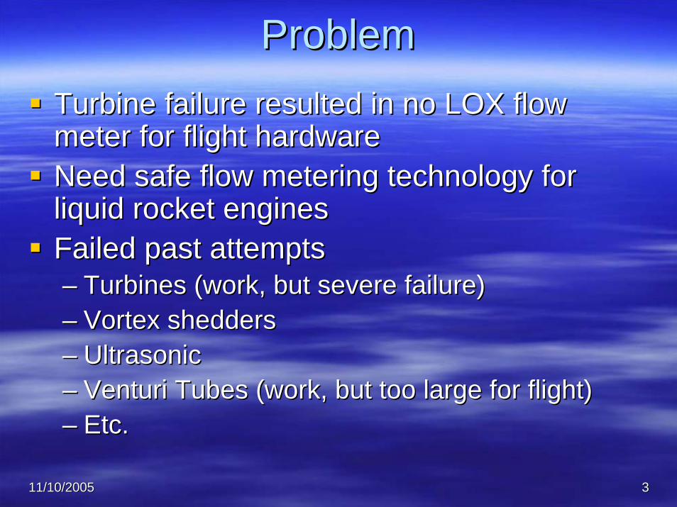
ProblemProblemTurbine failure resulted in no LOX flow Turbine failure resulted in no LOX flow meter for flight hardwaremeter for flight hardwareNeed safe flow metering technology for Need safe flow metering technology for liquid rocket enginesliquid rocket enginesFailed past attemptsFailed past attempts–– Turbines (work, but severe failure)Turbines (work, but severe failure)–– Vortex sheddersVortex shedders–– UltrasonicUltrasonic–– Venturi Tubes (work, but too large for flight)Venturi Tubes (work, but too large for flight)–– Etc.Etc.

11/10/200511/10/2005 44
NASA Flow Meter RequirementsNASA Flow Meter Requirements
Different fluids: LH2, LOX, Different fluids: LH2, LOX, RP1, etc.RP1, etc.Different physical states: Different physical states: Gas, Liquid, MultiGas, Liquid, Multi--PhasePhaseWide range (both high and Wide range (both high and low) in temperature, low) in temperature, pressure, vibration and pressure, vibration and flow conditionsflow conditionsVery low flow intrusion with Very low flow intrusion with near full pressure recoverynear full pressure recoveryNo moving partsNo moving partsMinimal piping Minimal piping requirementsrequirements
DropDrop--in replacement of an in replacement of an orificeorifice--plateplateRobust mechanical designRobust mechanical designHighly accurate and Highly accurate and repeatable flow repeatable flow measurementmeasurementEasy calibration and Easy calibration and maintenancemaintenanceNeed for high throughNeed for high through--put put flow areas with low flow flow areas with low flow restrictionrestriction
Most needs are common with industrial needs…

11/10/200511/10/2005 55
Balanced Flow Meter SolutionBalanced Flow Meter SolutionNASA patented technology #10/750,628NASA patented technology #10/750,628Allows engine measurements where none Allows engine measurements where none were beforewere before
Ability to condition or measure flow while Ability to condition or measure flow while improving velocity or other profilesimproving velocity or other profiles
Provides flow measurement, conditioning, Provides flow measurement, conditioning, and controlled restriction performanceand controlled restriction performance
Ability to function with minimal straight Ability to function with minimal straight pipe runpipe run
Measure mass flow rates, fluid volumetric Measure mass flow rates, fluid volumetric flow rates and density simultaneouslyflow rates and density simultaneously
Sensor set up can provide a triple Sensor set up can provide a triple redundant measurement systemredundant measurement system
Successfully fielded by industrySuccessfully fielded by industry
• Beta = 0.9• 7.5” NDP• Diff. pressure rated at 150 psi
Possible configuration…

11/10/200511/10/2005 66
What is Balanced Flow Technology?What is Balanced Flow Technology?A thin, multiA thin, multi--hole orifice plate with holes sized hole orifice plate with holes sized and placed per a unique set of equations to and placed per a unique set of equations to produce mass flow, volumetric flow, kinetic produce mass flow, volumetric flow, kinetic energy, or momentum BALANCE across the energy, or momentum BALANCE across the face of the plateface of the plate
ChevronChevron--Texaco 18 Texaco 18 inch Commercial inch Commercial
PlatePlate

11/10/200511/10/2005 77
How Does It Perform?How Does It Perform?
• 10X better accuracy• 2X faster pressure recovery
(shorter distance)• 15X noise reduction
• 2.5X less permanent pressure loss
• Exclusively licensed through NASA by A+FlowTek for commercialization
Comparison of standard orifice to balanced flow meter, both with 27.1% open area
Results based on compressed gas testing

11/10/200511/10/2005 88
Configurations Tested in 2004Configurations Tested in 2004
Figure 1 Slotted Configuration
Figure 2 Iron Cross Configuration
Figure 3 Single Ring of Holes Configuration
Figure 4 Custom Hole Configuration
Permanent pressure loss, accuracy and discharge coefficient comparable with a Venturi meter!

11/10/200511/10/2005 99
Balanced Flow Meter CharacteristicsBalanced Flow Meter Characteristics–– Minimal straight pipe run requirementsMinimal straight pipe run requirements——BFM has less BFM has less
than 0.5 X pipe diameter straight pipe requirementthan 0.5 X pipe diameter straight pipe requirement–– Only requires 0.25 to 0.5 inch thickness and Only requires 0.25 to 0.5 inch thickness and
approximately 3 PSI across the plate to condition and approximately 3 PSI across the plate to condition and monitor flowmonitor flow
–– Relatively low cost to build and operateRelatively low cost to build and operate–– Accuracy comparable to Venturi metersAccuracy comparable to Venturi meters
–– ConsCons——similar limitations as standard orificesimilar limitations as standard orificeNot good for pulsing flowNot good for pulsing flowLimited turn downLimited turn down
–– Testing methods based on American Petroleum Institute Testing methods based on American Petroleum Institute (API) Manual of Petroleum Measurement Standards 5.7(API) Manual of Petroleum Measurement Standards 5.7

11/10/200511/10/2005 1010
How Does it Work?How Does it Work?
Basic design based on multiBasic design based on multi--hole orifice hole orifice plateplateBasic relation is the Bernoulli equationBasic relation is the Bernoulli equation–– Requires custom Cd calculationRequires custom Cd calculation–– Long for Bernoulli equation required for high Long for Bernoulli equation required for high
accuracy applicationsaccuracy applications–– Highest accuracy applications require Highest accuracy applications require
physical properties modelsphysical properties modelsFlow proportional to SQRT of delta PFlow proportional to SQRT of delta PKey design factor is the hole distributionKey design factor is the hole distribution

11/10/200511/10/2005 1111
Technical BasisTechnical Basis——BFM Hole LayoutBFM Hole LayoutPlate hole layoutPlate hole layout basic equationbasic equation
κρκρAVAVnn = Constant for each hole= Constant for each hole = = ((κρκρAVAVnn))11 = = ((κρκρAVAVnn))22 = = …… = = ((κρκρAVAVnn))II
At At κκ11ρρ11 ~ ~ κκiiρρI,I,AAii/A/A11 = (V= (V11/V/Vii))nn
To simplify, let n = 1To simplify, let n = 1AAii/A/A11 = V= V11/V/Vii
Example, given a velocity distribution functionExample, given a velocity distribution functionVVrr//VVmaxmax = (1 = (1 -- RRrr/R/Rwallwall))1/71/7
Radial velocity ratiosRadial velocity ratiosVV11/V/Vii = ((1 = ((1 –– RR11/R/Rpp)/(1 )/(1 -- RRii/R/Rpp))))1/71/7 = A= Aii/A/A11
Nomenclature:Nomenclature:•• κκ: fluid flow correction factor: fluid flow correction factor•• ρρ: density of fluid: density of fluid•• A: sum of areas at given radiusA: sum of areas at given radius•• V: fluid velocity at radius rV: fluid velocity at radius r•• b: selected balancing constantb: selected balancing constant•• VmaxVmax: velocity at r=0, pipe center: velocity at r=0, pipe center•• RwallRwall: velocity at pipe wall: velocity at pipe wall

11/10/200511/10/2005 1212
Technical BasisTechnical Basis——BFM Hole Layout BFM Hole Layout Cont.Cont.
Subsequent radial areasSubsequent radial areasAAii = A= A11((1 ((1 -- RR11/R/Rpp)/(1 )/(1 -- RRii/R/Rpp))))1/71/7
Radial area equationRadial area equationFrom From ββ2 2 = = AAtotaltotal / / AApipepipeAnd multiple holes,And multiple holes,
AA00 + A+ A11 + A+ A22 + + …………. + A. + Ann = = AAtotaltotal = = ββ22AApipepipe
Hole diameters at radius i Hole diameters at radius i DDii = (4A= (4Aii//ππN)N)1/21/2
Sheer stresses typically lower than standard, singleSheer stresses typically lower than standard, single--hole orifice! hole orifice!

11/10/200511/10/2005 1313
Tech BasisTech Basis--Bernoulli EquationBernoulli EquationBernoulli EquationBernoulli Equation——longer formlonger form
(P(Paa--PPbb)/)/ρρ + g(+ g(ZZaa -- ZZbb)/)/ggcc + (+ (ααaaVVaa22 -- ααbbVVbb
22)/2g)/2gcc -- hhfbfb = 0 = 0
Equation of ContinuityEquation of Continuity((ρρAV)AV)aa = m = (= m = (ρρAV)AV)bb
Simplified Bernoulli EquationSimplified Bernoulli Equation——assume constant assume constant density (incompressible), frictionless fluid (zero density (incompressible), frictionless fluid (zero viscosity), and no elevation changesviscosity), and no elevation changes
(P(Paa--PPbb)/)/ρρ + (V+ (Vaa22 -- VVbb
22)/2g)/2gcc = 0 = 0
Equations from ISO 5167Equations from ISO 5167--1, API 14.3.1, etc. Derivations in 1, API 14.3.1, etc. Derivations in multiple texts.multiple texts.

11/10/200511/10/2005 1414
Tech BasisTech Basis--Bernoulli EquationBernoulli EquationBeta area ratioBeta area ratio
((ββ))22 = = AAbb//AAaa
Flow EquationFlow Equationm = Cm = CDDYAYAbb(2g(2gccρρaa(P(Paa -- PPbb)/(1 )/(1 -- ββ44))))1/21/2
There can be longer equation forms with many other factors, suchThere can be longer equation forms with many other factors, suchas expansion factors, compressibility factors, meter correction as expansion factors, compressibility factors, meter correction factors, etc.factors, etc.
Typical UncertaintiesTypical Uncertainties–– Gas Flow: +/Gas Flow: +/-- 0.67% (API 14.3.1)0.67% (API 14.3.1)–– Liquid Flow: +/Liquid Flow: +/-- 0.57% (API 14.3.1)0.57% (API 14.3.1)–– Spec values are EXTREMELY Spec values are EXTREMELY
conservativeconservative
BFM Lab AccuraciesBFM Lab Accuracies–– +/+/-- 2% without calibration2% without calibration–– +/+/-- 1.0% long equation1.0% long equation–– Calculated +/Calculated +/-- 0.1% custom 0.1% custom
equation, calibratedequation, calibrated–– BFM calculated value: +/BFM calculated value: +/--
0.25% (Directly measured)0.25% (Directly measured)

11/10/200511/10/2005 1515
MSFC Water Calibration FacilityMSFC Water Calibration FacilityNational Institute of National Institute of Standards and Test Standards and Test (NIST) certified(NIST) certifiedVolumetric systemVolumetric system5000 gallons5000 gallonsPump or gravity fedPump or gravity fedQuad Quad deionizeddeionized waterwater0.25% flow accuracy 0.25% flow accuracy over unit of time over unit of time between level sensorsbetween level sensors0.15% repeatability at 0.15% repeatability at given flow set pointgiven flow set point

11/10/200511/10/2005 1616
MSFC Gas Calibration FacilityMSFC Gas Calibration FacilityPositive displacement, Positive displacement, inverted cylinder inverted cylinder systemsystemNIST certifiedNIST certifiedMultiple gases Multiple gases including N, He, Air, including N, He, Air, Argon, FreonArgon, Freon0.01 to 3000 psi 0.01 to 3000 psi operationoperation.01 to 400 SCFM.01 to 400 SCFMAccuracy & Accuracy & repeatability???repeatability???

11/10/200511/10/2005 1717
Cd and K Factor ComparisonsCd and K Factor ComparisonsBalanced Flow Meter plate performance, Balanced Flow Meter plate performance,
from minimum flows to sonicfrom minimum flows to sonicBETA 0.25 0.500 0.521 0.650 0.500,fouled 0.500,elbow
Avg Cd 0.892 0.882 0.881 0.911 0.824 0.848 Cd Dev 0.032 0.001 0.009 0.010 0.038 0.008 Avg K Val 287.1 16.3 13.2 4.0 15.65 18.63 K Dev 20.8 0.60 0.53 0.16 1.23 0.38
BETA 0.25 0.500 0.521 0.650 Venturi K, Cd=0.96 134.2 5.8 4.7 1.3 Venturi K, Cd=0.80 255.9 12.9 10.7 3.5 BFM K 287.1 16.3 13.2 4.0 Orifice K 669.4 31.5 25.7 7.4
Note: Venturi values do not include downstream losses.

11/10/200511/10/2005 1818
BFM vs. Orifice Flow EquationBFM vs. Orifice Flow Equation

11/10/200511/10/2005 1919
BFM Calibration CdBFM Calibration CdORIFICE/VENTURI COEFFICIENT (Cd) PLOT
Balanced Inline and Staggered beta 0.500 Flat side upstream.xls
0
0.2
0.4
0.6
0.8
1
1.2
1.4
0 2 4 6 8 10 12 14
TOTAL DELTA PRESSURE (PSI) - 10 DIAMETERS UPSTREAM MINUS ATM
OR
IFIC
E/VE
NTU
RI C
OEF
FIC
IEN
T, C
D V
ALU
E
CD_ORIFICE_REFCD_ORIFICE_USFLG_THROATCD_ORIFICE_USFLG_DSFLGCD_VENTURI_USFLG_THROATCD_VENTURI_USFLG_DSFLGCD_VENTURI_REF
NOTE: PIPE ID = 1.5 INCH
Theoretical lines, notReal data

11/10/200511/10/2005 2020
BFM K Factor PlotsBFM K Factor PlotsVELOCITY HEAD LOSS CONSTANT (K) PLOT
Balanced Inline beta 0.650.xls
0
1
2
3
4
5
6
7
8
0 0.5 1 1.5 2 2.5 3 3.5
TOTAL DELTA PRESSURE (PSI) - 10 DIAMETERS UPSTREAM MINUS ATM
VELO
CTY
HEA
D, K
VA
LUE
KVHEAD_ORIFICE_REFKVHEAD_10US_4DSKVHEAD_USFLG_DSFLGKVHEAD_VENTURI_REF
NOTE: PIPE ID = 1.5 INCH
Theoretical lines, notReal data
11/10/200511/10/2005 2121
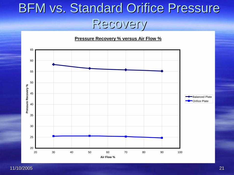
BFM vs. Standard Orifice Pressure BFM vs. Standard Orifice Pressure RecoveryRecovery
Pressure Recovery % versus Air Flow %
20
25
30
35
40
45
50
55
60
65
20 30 40 50 60 70 80 90 100
Air Flow %
Pres
sure
Rec
over
y %
Balanced PlateOrifice Plate

11/10/200511/10/2005 2222
BFM vs. Orifice Acoustic NoiseBFM vs. Orifice Acoustic NoiseFlow Meter Noise @ 1 ft and 90% Air Flow
90.00
95.00
100.00
105.00
110.00
115.00
120.00
Balanced Plate Orifice Plate
Plate Type
Noi
se L
evel
in d
B @
1 ft

11/10/200511/10/2005 2323
Why Does This Matter?Why Does This Matter?Believe will meet NASA liquid engine flow meter Believe will meet NASA liquid engine flow meter requirementsrequirements——test program ontest program on--goinggoingProvides safe, rugged, robust flow meterProvides safe, rugged, robust flow meterProvides dropProvides drop--in orifice meter replacementin orifice meter replacementIncreases fluid system efficiency to save $$$Increases fluid system efficiency to save $$$Provides multiple benefits with relative lowProvides multiple benefits with relative low--costcost–– Reduced piping requirementsReduced piping requirements–– Reduced noise generation (EPA regulations)Reduced noise generation (EPA regulations)–– No moving parts, simple designNo moving parts, simple design–– Capable of simultaneous fluid metering and flow profile conditioCapable of simultaneous fluid metering and flow profile conditioningning–– Robust calibrationRobust calibration——well defined and characterized traditional well defined and characterized traditional
techniquestechniques–– Typical +/Typical +/-- 0.15% accuracy of measured flow throughout 0.15% accuracy of measured flow throughout
measurement rangemeasurement range–– Reduced pump energy requirementsReduced pump energy requirements
High pressure recoveryHigh pressure recoveryLow permanent pressure lossLow permanent pressure loss

11/10/200511/10/2005 2424
Lessons LearnedLessons LearnedAlways double check flow meter vendor claims, Always double check flow meter vendor claims, flow equations, and calibration techniquesflow equations, and calibration techniquesThere are hundreds of emerging flow metering There are hundreds of emerging flow metering technologiestechnologies——stringently define your unique stringently define your unique requirementsrequirementsDetermine best calibration method for your Determine best calibration method for your applicationapplication——inin--situ system level calibration vs. situ system level calibration vs. typical individual component calibrationtypical individual component calibrationTest/Calibrate as you intend to use the meterTest/Calibrate as you intend to use the meter——If If possible, test your new meter!possible, test your new meter!Follow standards for instrument placement, Follow standards for instrument placement, uncertainties, etc., but not for plate thickness!uncertainties, etc., but not for plate thickness!

11/10/200511/10/2005 2525
Useful ReferencesUseful References
The Consumer Guide to Differential Pressure Flow Transmitters byThe Consumer Guide to Differential Pressure Flow Transmitters by David W. David W. Spitzer Spitzer and Walt and Walt BoyesBoyes, Published by Copperhill and Pointer, Inc., ISBN 1, Published by Copperhill and Pointer, Inc., ISBN 1--932095932095--0303--99API Manual of Petroleum Measurement Standards 5.7, Testing ProtoAPI Manual of Petroleum Measurement Standards 5.7, Testing Protocol for col for Differential Pressure Flow Measurement DevicesDifferential Pressure Flow Measurement DevicesAPI Manual of Petroleum Measurement Standards Ch. 14API Manual of Petroleum Measurement Standards Ch. 14——Natural Gas Fluids Natural Gas Fluids Measurement, Section 3Measurement, Section 3——Concentric, SquareConcentric, Square--Edged Orifice Meters, Part 1Edged Orifice Meters, Part 1——General Equations and uncertainty GuidelinesGeneral Equations and uncertainty GuidelinesAPI Manual of Petroleum Measurement Standards Ch. 14API Manual of Petroleum Measurement Standards Ch. 14——Natural Gas Fluids Natural Gas Fluids Measurement, Section 3Measurement, Section 3——Concentric, SquareConcentric, Square--Edged Orifice Meters, Part 2Edged Orifice Meters, Part 2——Specification and Installation RequirementsSpecification and Installation RequirementsISO 5167ISO 5167--1 Measurement of fluid flow by means of pressure differential 1 Measurement of fluid flow by means of pressure differential devices inserted in circular crossdevices inserted in circular cross--section conduits running full, Part 1: General section conduits running full, Part 1: General principles and requirementsprinciples and requirementsISO 5167ISO 5167--1 Measurement of fluid flow by means of pressure differential 1 Measurement of fluid flow by means of pressure differential devices inserted in circular crossdevices inserted in circular cross--section conduits running full, Part 2: Orifice section conduits running full, Part 2: Orifice PlatesPlatesThe measurement, instrumentation, and sensors handbook, John G. The measurement, instrumentation, and sensors handbook, John G. Webster, Webster, CRC Press & IEEE PressCRC Press & IEEE Press

11/10/200511/10/2005 2626
For Additional Information:For Additional Information:Anthony R. KelleyAnthony R. Kelley
EV43 NASA/MSFCEV43 NASA/MSFCHuntsville, AL 35812Huntsville, AL 35812
[email protected]@nasa.gov256256--544544--76467646
Willy OeffingerWilly OeffingerAlpha Process Sales, Inc.Alpha Process Sales, Inc.
P.O. Box 2003P.O. Box 2003Sugar Land, TX 77487Sugar Land, TX 77487--20032003
[email protected]@alphaps.com281281--240240--45054505