Embed Size (px)
Citation preview
Backward wave radiation from negative permittivity waveguides and its use for THz
subwavelength imaging Alexey A. Basharin,1,* Maria Kafesaki,1,2 Eleftherios N. Economou,1,3 and Costas M.
Soukoulis1,4 1 Institute of Electronic Structure and Laser (IESL), Foundation for Research and Technology Hellas (FORTH), P.O.
Box 1385, 71110 Heraklion, Crete, Greece 2 Department of Materials Science and Technology, University of Crete, 71003 Heraklion, Greece
3 Department of Physics, University of Crete, 71003 Heraklion, Greece 4 Ames Laboratory-USDOE, and Department of Physics and Astronomy, Iowa State University, Ames, Iowa 50011,
USA *[email protected]
Abstract: In this paper we demonstrate the possibility of backward radiation from a negative permittivity planar (slab) waveguide. Furthermore, we show that backward radiation can be used to achieve sub-wavelength imaging of a point source placed close to such a slab or to a periodic layered system of slabs. Finally, we demonstrate backward-radiation-based imaging in the case of realistic materials operating in the THz regime, such as polaritonic alkali-halide systems. ©2012 Optical Society of America OCIS codes: (230.7390) Waveguide, planar; (160.3918) Metamaterials; (260.1180) Anisotropic media.
References and links 1. V. G. Veselago, “The electrodynamics of substances with simultaneously negative value of ε and μ,” Sov. Phys.
Usp. 10(4), 509–514 (1968). 2. J. B. Pendry, “Negative refraction makes a perfect lens,” Phys. Rev. Lett. 85(18), 3966–3969 (2000). 3. D. R. Smith, W. J. Padilla, D. C. Vier, S. C. Nemat-Nasser, and S. Schultz, “Composite medium with
simultaneously negative permeability and permittivity,” Phys. Rev. Lett. 84(18), 4184–4187 (2000). 4. V. M. Shalaev, “Optical negative-index metamaterials,” Nat. Photonics 1(1), 41–48 (2007). 5. C. M. Soukoulis, S. Linden, and M. Wegener, “Negative refractive index at optical wavelengths,” Science
315(5808), 47–49 (2007). 6. D. R. Smith, J. B. Pendry, and M. C. K. Wiltshire, “Metamaterials and negative refractive index,” Science
305(5685), 788–792 (2004). 7. C. Pecharroman, F. Esteban-Bategon, J. F. Bartolomé, S. López-Esteban and J. S. Moya, “New percolative
BaTiO3–Ni composites with a high and frequency-independent dielectric constant (ϵr ≈ 80000),” Adv. Mater. (Deerfield Beach Fla.) 13(20), 1541–1544 (2001).
8. N. Engheta, “Circuits with light at nanoscales: optical nanocircuits inspired by metamaterials,” Science 317(5845), 1698–1702 (2007).
9. A. Fang, T. Koschny, and C. M. Soukoulis, “Self-consistent calculation of metamaterials with gain,” Phys. Rev. B 79, 245127 (2009).
10. K. L. Tsakmakidis and O. Hess, “Optics: watch your back,” Nature 451(7174), 27 (2008). 11. A. Greenleaf, Y. Kurylev, M. Lassas, and G. Uhlmann, “Electromagnetic wormholes and virtual magnetic
monopoles from metamaterials,” Phys. Rev. Lett. 99(18), 183901 (2007). 12. J. B. Pendry, D. Schurig, and D. R. Smith, “Controlling electromagnetic fields,” Science 312(5781), 1780–1782
(2006). 13. U. Leonhardt, “Optical conformal mapping,” Science 312(5781), 1777–1780 (2006). 14. N. P. Balabukha, A. A. Basharin, and V. N. Semenenko, “Effect of backward radiation of electromagnetic waves
by a metamaterial waveguide structure,” JETP Lett. 89(10), 500–505 (2009). 15. A. Grbic and G. V. Eleftheriades, “Experimental verification of backward-wave radiation from a negative
refractive index metamaterial,” J. Appl. Phys. 92(10), 5930–5935 (2002). 16. C. Caloz and T. Itoh, Electromagnetic Metamaterials: Transmission Line Theory and Microwave Applications
(Wiley, New York, 2006). 17. A. A. Basharin, N. P. Balabukha, and V. N. Semenenko, “The radiation from a planar metamaterial waveguide,”
J. Appl. Phys. 107(11), 113301 (2010).
#161926 - $15.00 USD Received 20 Jan 2012; revised 14 Mar 2012; accepted 16 Mar 2012; published 23 May 2012(C) 2012 OSA 4 June 2012 / Vol. 20, No. 12 / OPTICS EXPRESS 12752
18. H. Liu and K. J. Webb, “Leaky wave radiation from planar anisotropic metamaterial slabs,” Phys. Rev. B 81(20), 201404 (2010).
19. T. Tamir and F. Y. Kou, “Varieties of leaky waves and their excitation along multilayered structures,” IEEE J. Quantum Electron. 22(4), 544–551 (1986).
20. M. Laroche, R. Carminati, and J. J. Greffet, “Coherent thermal antenna using a photonic crystal slab,” Phys. Rev. Lett. 96(12), 123903 (2006).
21. E. Colak, H. Caglayan, A. O. Cakmak, A. D. Villa, F. Capolino, and E. Ozbay, “Frequency dependent steering with backward leaky waves via photonic crystal interface layer,” Opt. Express 17(12), 9879–9890 (2009).
22. A. Micco, V. Galdi, F. Capolino, A. DellaVilla, V. Pierro, S. Enoch, and G. Tayeb, “Directive emission from defect-free dodecagonal photonic quasicrystals: A leaky wave characterization,” Phys. Rev. B 79(7), 075110 (2009).
23. M. B. Vinogradova, O. V. Rudenko, and A. P. Sukhorukov, Theory of Waves (Nauka, Moscow, 1990). 24. B. Prade, J. Y. Vinet, and A. Mysyrowicz, “Guided optical waves in planar heterostructures with negative
dielectric constant,” Phys. Rev. B Condens. Matter 44(24), 13556–13572 (1991). 25. E. N. Economou, “Surface plasmons in thin films,” Phys. Rev. 182(2), 539–554 (1969). 26. Y. N. Kuznetsov and D. I. Sementsov, “Interference of copropagating and counterpropagating surface waves,”
Opt. Spectrosc. 97(4), 614–616 (2004). 27. S. A. Afanas’ev and D. I. Sementsov, “Energy fluxes during the interference of electromagnetic waves,” Sov.
Phys. Usp. 51(4), 355–361 (2008). 28. W. Neil, Ashcroft and N. David Mermin, Solid State Physic (Holt, Rinehart and Winston, 1976). 29. E. D. Palik, Handbook of Optical Constants of Solids (Academic Press Inc., Orlando, 1985). 30. R. Ruppin, “Surface polaritons of a left-handed material slab,” J. Phys. Condens. Matter 13(9), 1811–1818
(2001). 31. S. Foteinopoulou, M. Kafesaki, E. N. Economou, and C. M. Soukoulis, “Two-dimensional polaritonic photonic
crystals as terahertz uniaxial metamaterials,” Phys. Rev. B 84(3), 035128 (2011). 32. A. Reyes-Coronado, M. F. Acosta, R. I. Merino, V. M. Orera, G. Genanakis, N. Katsarakis, M. Kafesaki, Ch.
Mavidis, J. G. de Abajo, E. N. Economou, and C. M. Soukoulis, “Self-organization approach for THz polaritonic metamaterials,” submitted to Opt. Express (2012).
33. S. A. Ramakrishna, J. B. Pendry, M. C. K. Wiltshire, and W. J. Stewart, “Imaging the near field,” J. Mod. Opt. 50, 1419–1430 (2003).
34. B. Wood, J. B. Pendry, and D. P. Tsai, “Directed subwavelength imaging using a layered metal-dielectric system,” Phys. Rev. B 74(11), 115116 (2006).
35. L. V. Alekseyev and E. Narimanov, “Slow light and 3D imaging with non-magnetic negative index systems,” Opt. Express 14(23), 11184–11193 (2006).
1. Introduction
The interest in so-called left-handed metamaterials (LHM) or double negative (DNG) metamaterials, i.e. metamaterials with both electrical permittivity and magnetic permeability negative, has been grown recently. The LHM properties were predicted by Veselago [1] in 1967, but the attention was renewed quite recently, due to the works by Pendry [2], and had stimulated interest also in other categories of metamaterials, besides left-handed media, such as permittivity near zero materials, large permittivity materials, etc. The reason behind the growing interest about metamaterials is the unusual properties and capabilities of those materials, such as negative refractive index [1–6], giant dielectric constant [7], permittivity close to zero [8], near-field focusing and subwavelength imaging [9].
In 2008, Tsakmakidis and Hess [10] raised the question: “Can we see what is happening behind us by using metamaterials?” They suggested that this would be possible using a metamaterial construction of the form of the recently proposed “electromagnetic wormhole” [11]. This electromagnetic wormhole can be used to create “electromagnetic channels” that connect eyes and the image behind, making possible to see behind yourself, and can be constructed by using the transformation optics approach [12, 13].
The inverse problem is the backward radiation: There is a directional waveguide antenna, which consists of a metamaterial with negative refractive index. Backward wave (i.e. with Poynting vector antiparallel to wavevector) is excited in the waveguide. Due to the negative refraction of this wave at the boundaries of the waveguide, the wave leaked out from the waveguide boundaries (i.e. the wave emitted by the waveguide antenna) will propagate in the direction opposite to the wave propagating in the waveguide. Thus this waveguide antenna will radiate backward instead of the forward direction. It is a flashlight that can shine back.
Such an antenna has been realized experimentally on the form of a tube-like DNG waveguide [14]. The antenna was tuned to radiate at the frequency of 3 GHz, where the metamaterial forming the waveguide had negative values of permittivity and permeability.
#161926 - $15.00 USD Received 20 Jan 2012; revised 14 Mar 2012; accepted 16 Mar 2012; published 23 May 2012(C) 2012 OSA 4 June 2012 / Vol. 20, No. 12 / OPTICS EXPRESS 12753

Due to the excitation of backward waves in the waveguide the antenna radiated mainly in the backward direction, i.e. with a maximum main lobe lying in the back of the antenna. Similar results were obtained by Grbic and Eleftheriades [15] and by Caloz and Itoh [16] employing transmission lines antennas.
In Ref [17]. it is analytically shown that backward radiation can be achieved not only in DNG media but also in media with only permittivity negative. In particular, backward radiation is possible for an even TM mode in a planar waveguide, provided that 2 2( / )1 2 1 2k kεε < − , where ε1, k1 are the relative permittivity and the transverse wave number (in respect to the direction of the guide) in the waveguide, and ε2, k2 the permittivity and the transverse wave number in the media surrounding the waveguide; i.e., backward radiation is possible for a negative permittivity waveguide in air or inside a dielectric medium.
Approximately at the same time with Ref [17], Liu and Webb [18] demonstrated the possibility of backward radiation from an anisotropic uniaxial waveguide, provided that only the permittivity component in the directions perpendicular to the waveguide is negative (and the permittivity component along the waveguide direction positive).
Backward radiation though has not been discussed only in connection with metamaterials. Earlier works concerning conventional wave systems reported backward radiation antennas, made of planar multilayered structures [19] and two-dimensional photonic crystals [20–22].
In this work, we exploit the backward radiation from a negative permittivity planar waveguide (slab) to achieve superlensing in a layered system made of many parallel slabs. First we analyze the modes in a single negative permittivity planar waveguide and we discuss the conditions for the achievement of backward radiation. Then we demonstrate how the backward radiation can be used to achieve subwavelength imaging of a point source placed close to a negative permittivity slab as well as a layered system of such slabs. We demonstrate this imaging in the THz regime, employing layer systems made of polaritonic materials, in particular LiF and NaCl.
2. Characteristics of waveguides with negative permittivity
To begin our investigation, we consider a planar semi-infinite along z waveguide, as shown in Fig. 1. We denote the relative permittivity and permeability of the waveguide and of the surrounding space as ε1, μ1 and ε2, μ2, respectively. The fields of the even TM modes in the waveguide are expressed in terms of the Hertz vector, Πz, with the time dependence exp(–iωt) omitted, as follows [23]:
1
2
sin( ) exp( ) for
exp( )exp( ) for ,
ez
ez
A k x ihz x a
C k x ihz x a
Π = <
Π = − >
(1)
20
0
( )
( ) ,
ez
x
ee z
z z
ez
y
Ex z
E kz z
H ikx
εµ
ε
∂Π∂=∂ ∂
∂Π∂= Π +
∂ ∂∂Π
=∂
(2)
where A and C are constants, h is the wave vector component along the waveguide direction (z), and d = 2a is the thickness of the waveguide (along x-direction).
The z component of the time averaged Poynting vector is
*1 Re( ) ,2z x yS E H= (3)
where the symbol * denotes the complex conjugate.
#161926 - $15.00 USD Received 20 Jan 2012; revised 14 Mar 2012; accepted 16 Mar 2012; published 23 May 2012(C) 2012 OSA 4 June 2012 / Vol. 20, No. 12 / OPTICS EXPRESS 12754
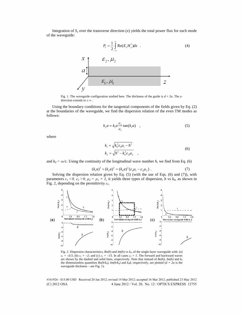
Integration of Sz over the transverse direction (x) yields the total power flux for each mode of the waveguide:
*1 Re( ) .2z x yP E H dx
∞
−∞
= ∫ (4)
Fig. 1. The waveguide configuration studied here. The thickness of the guide is d = 2a. The y-direction extends to ± ∞ .
Using the boundary conditions for the tangential components of the fields given by Eq. (2) at the boundaries of the waveguide, we find the dispersion relation of the even TM modes as follows:
22 1 1
1
tan( ) ,k a k a k aεε
= (5)
where
2 2
1 0 1 1
2 22 0 2 2 ,
k k h
k h k
ε µ
ε µ
= −
= − (6)
and k0 = ω/c. Using the continuity of the longitudinal wave number h, we find from Eq. (6)
2 2 21 2 0 1 1 2 2( ) ( ) ( ) ( ) .k a k a k a ε µ ε µ+ = − (7)
Solving the dispersion relation given by Eq. (5) (with the use of Eqs. (6) and (7)), with parameters ε1 <0, ε2 >0, μ2 = μ1 = 1, it yields three types of dispersion, h vs k0, as shown in Fig. 2, depending on the permittivity ε1.
Fig. 2. Dispersion characteristics, Re(h) and Im(h) vs k0, of the single-layer waveguide with: (a) ε1 = –0.5; (b) ε1 = −2; and (c) ε1 = −15. In all cases ε2 = 1. The forward and backward waves are shown by the dashed and solid lines, respectively. Note that instead of Re(h), Im(h) and k0 the dimensionless quantities Re(h/k0), Im(h/k0) and k0d, respectively, are plotted (d = 2a is the waveguide thickness – see Fig. 1).
#161926 - $15.00 USD Received 20 Jan 2012; revised 14 Mar 2012; accepted 16 Mar 2012; published 23 May 2012(C) 2012 OSA 4 June 2012 / Vol. 20, No. 12 / OPTICS EXPRESS 12755
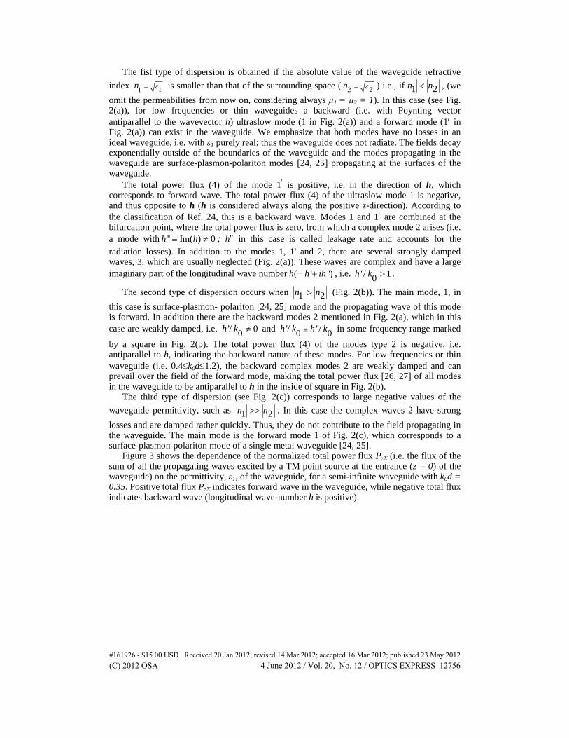
The fist type of dispersion is obtained if the absolute value of the waveguide refractive index 11n ε= is smaller than that of the surrounding space ( 22n ε= ) i.e., if 1 2n n< , (we omit the permeabilities from now on, considering always μ1 = μ2 = 1). In this case (see Fig. 2(a)), for low frequencies or thin waveguides a backward (i.e. with Poynting vector antiparallel to the wavevector h) ultraslow mode (1 in Fig. 2(a)) and a forward mode (1′ in Fig. 2(a)) can exist in the waveguide. We emphasize that both modes have no losses in an ideal waveguide, i.e. with ε1 purely real; thus the waveguide does not radiate. The fields decay exponentially outside of the boundaries of the waveguide and the modes propagating in the waveguide are surface-plasmon-polariton modes [24, 25] propagating at the surfaces of the waveguide.
The total power flux (4) of the mode 1′ is positive, i.e. in the direction of h, which corresponds to forward wave. The total power flux (4) of the ultraslow mode 1 is negative, and thus opposite to h (h is considered always along the positive z-direction). According to the classification of Ref. 24, this is a backward wave. Modes 1 and 1′ are combined at the bifurcation point, where the total power flux is zero, from which a complex mode 2 arises (i.e. a mode with '' Im( ) 0h h≡ ≠ ; h″ in this case is called leakage rate and accounts for the radiation losses). In addition to the modes 1, 1' and 2, there are several strongly damped waves, 3, which are usually neglected (Fig. 2(a)). These waves are complex and have a large imaginary part of the longitudinal wave number ( ' '')h h ih= + , i.e. ''/ 10h k > .
The second type of dispersion occurs when 1 2n n> (Fig. 2(b)). The main mode, 1, in this case is surface-plasmon- polariton [24, 25] mode and the propagating wave of this mode is forward. In addition there are the backward modes 2 mentioned in Fig. 2(a), which in this case are weakly damped, i.e. '/ 00h k ≠ and '/ ''/0 0h k h k≡ in some frequency range marked
by a square in Fig. 2(b). The total power flux (4) of the modes type 2 is negative, i.e. antiparallel to h, indicating the backward nature of these modes. For low frequencies or thin waveguide (i.e. 0.4≤k0d≤1.2), the backward complex modes 2 are weakly damped and can prevail over the field of the forward mode, making the total power flux [26, 27] of all modes in the waveguide to be antiparallel to h in the inside of square in Fig. 2(b).
The third type of dispersion (see Fig. 2(c)) corresponds to large negative values of the waveguide permittivity, such as 1 2n n>> . In this case the complex waves 2 have strong losses and are damped rather quickly. Thus, they do not contribute to the field propagating in the waveguide. The main mode is the forward mode 1 of Fig. 2(c), which corresponds to a surface-plasmon-polariton mode of a single metal waveguide [24, 25].
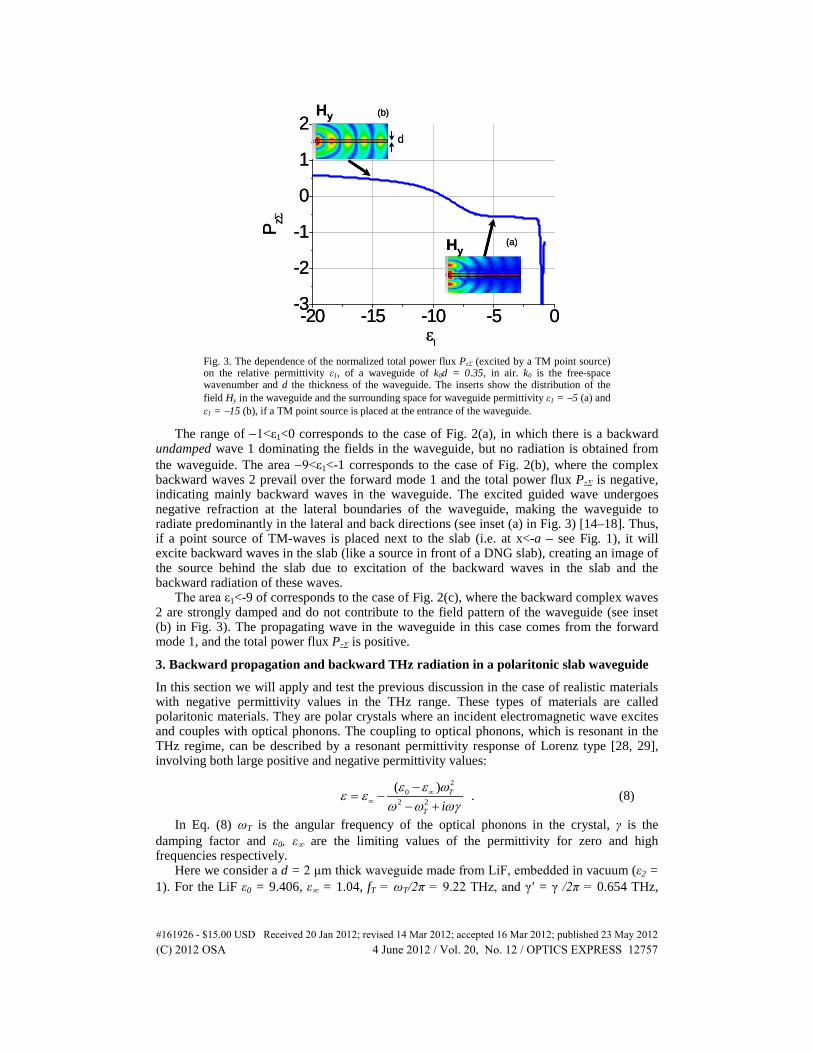
Figure 3 shows the dependence of the normalized total power flux PzΣ (i.e. the flux of the sum of all the propagating waves excited by a TM point source at the entrance (z = 0) of the waveguide) on the permittivity, ε1, of the waveguide, for a semi-infinite waveguide with k0d = 0.35. Positive total flux PzΣ indicates forward wave in the waveguide, while negative total flux indicates backward wave (longitudinal wave-number h is positive).
#161926 - $15.00 USD Received 20 Jan 2012; revised 14 Mar 2012; accepted 16 Mar 2012; published 23 May 2012(C) 2012 OSA 4 June 2012 / Vol. 20, No. 12 / OPTICS EXPRESS 12756
-20 -15 -10 -5 0-3
-2
-1
0
1
2
P zΣ
ε1
Hy
Hy
d
(b)
(a)
-20 -15 -10 -5 0-3
-2
-1
0
1
2
P zΣ
ε1
Hy
Hy
d
(b)
(a)
Fig. 3. The dependence of the normalized total power flux PzΣ (excited by a TM point source) on the relative permittivity ε1, of a waveguide of k0d = 0.35, in air. k0 is the free-space wavenumber and d the thickness of the waveguide. The inserts show the distribution of the field Hy in the waveguide and the surrounding space for waveguide permittivity ε1 = −5 (a) and ε1 = −15 (b), if a TM point source is placed at the entrance of the waveguide.
The range of −1<ε1<0 corresponds to the case of Fig. 2(a), in which there is a backward undamped wave 1 dominating the fields in the waveguide, but no radiation is obtained from the waveguide. The area −9<ε1<-1 corresponds to the case of Fig. 2(b), where the complex backward waves 2 prevail over the forward mode 1 and the total power flux PzΣ is negative, indicating mainly backward waves in the waveguide. The excited guided wave undergoes negative refraction at the lateral boundaries of the waveguide, making the waveguide to radiate predominantly in the lateral and back directions (see inset (a) in Fig. 3) [14–18]. Thus, if a point source of TM-waves is placed next to the slab (i.e. at x<-a – see Fig. 1), it will excite backward waves in the slab (like a source in front of a DNG slab), creating an image of the source behind the slab due to excitation of the backward waves in the slab and the backward radiation of these waves.
The area ε1<-9 of corresponds to the case of Fig. 2(c), where the backward complex waves 2 are strongly damped and do not contribute to the field pattern of the waveguide (see inset (b) in Fig. 3). The propagating wave in the waveguide in this case comes from the forward mode 1, and the total power flux PzΣ is positive.
3. Backward propagation and backward THz radiation in a polaritonic slab waveguide
In this section we will apply and test the previous discussion in the case of realistic materials with negative permittivity values in the THz range. These types of materials are called polaritonic materials. They are polar crystals where an incident electromagnetic wave excites and couples with optical phonons. The coupling to optical phonons, which is resonant in the THz regime, can be described by a resonant permittivity response of Lorenz type [28, 29], involving both large positive and negative permittivity values:
2
02 2
( ).T
T iε ε ω
ε εω ω ωγ
∞∞
−= −
− + (8)
In Eq. (8) ωT is the angular frequency of the optical phonons in the crystal, γ is the damping factor and ε0, ε∞ are the limiting values of the permittivity for zero and high frequencies respectively.
Here we consider a d = 2 μm thick waveguide made from LiF, embedded in vacuum (ε2 = 1). For the LiF ε0 = 9.406, ε∞ = 1.04, fT = ωT/2π = 9.22 THz, and γ' = γ /2π = 0.654 THz,
#161926 - $15.00 USD Received 20 Jan 2012; revised 14 Mar 2012; accepted 16 Mar 2012; published 23 May 2012(C) 2012 OSA 4 June 2012 / Vol. 20, No. 12 / OPTICS EXPRESS 12757
giving negative values for the LiF permittivity, εLiF, in the frequency f ( = ω/2π) range ~9-25 THz.
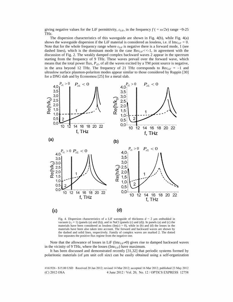
The dispersion characteristics of this waveguide are shown in Fig. 4(b), while Fig. 4(a) shows the waveguide dispersion if the LiF material is considered as lossless, i.e. if ImεLiF = 0. Note that for the whole frequency range where εLiF is negative there is a forward mode, 1 (see dashed lines), which is the dominant mode in the case ReεLiF<<-1, in agreement with the discussion of Fig. 2. The weakly damped complex backward waves 2 appear in the spectrum starting from the frequency of 9 THz. These waves prevail over the forward wave, which means that the total power flux, PzΣ, of all the waves excited by a TM point source is negative, in the area beyond 12 THz. The frequency of 21 THz corresponds to ReεLiF = −1 and ultraslow surface plasmon-polariton modes appear similar to those considered by Ruppin [30] for a DNG slab and by Economou [25] for a metal slab.
Re(
h/k 0
)
f, THz
0zP Σ <0zP Σ >
(a)
Re(
h/k 0
)
f, THz
0zP Σ <0zP Σ >
(b)
Re(
h/k 0
)
f, THz
0zP Σ > 0zP Σ <
(c)
Re(
h/k 0
)
f, THz
0zP Σ > 0zP Σ <
(d)
Re(
h/k 0
)
f, THz
0zP Σ <0zP Σ >
(a)
Re(
h/k 0
)
f, THz
0zP Σ <0zP Σ >
(a)
Re(
h/k 0
)
f, THz
0zP Σ <0zP Σ >
(b)
Re(
h/k 0
)
f, THz
0zP Σ <0zP Σ >
(b)
Re(
h/k 0
)
f, THz
0zP Σ > 0zP Σ <
(c)
Re(
h/k 0
)
f, THz
0zP Σ > 0zP Σ <
(c)
Re(
h/k 0
)
f, THz
0zP Σ > 0zP Σ <
(d)
Re(
h/k 0
)
f, THz
0zP Σ > 0zP Σ <
Re(
h/k 0
)
f, THz
0zP Σ > 0zP Σ <
(d)
Fig. 4. Dispersion characteristics of a LiF waveguide of thickness d = 2 μm embedded in vacuum (ε2 = 1) (panels (a) and (b)), and in NaCl (panels (c) and (d)). In panels (a) and (c) the materials have been considered as lossless (Im(ε) = 0), while in (b) and (d) the losses in the materials have been also taken into account. The forward and backward waves are shown by the dashed and solid lines, respectively. Family of complex waves are marked 2. The dotted line separates the positive flux regime from the negative one.
Note that the allowance of losses in LiF (ImεLiF≠0) gives rise to damped backward waves in the vicinity of 9 THz, where the losses (ImεLiF) have maximum.
It has been discussed and demonstrated recently [31,32] that periodic systems formed by polaritonic materials (of μm unit cell size) can be easily obtained using a self-organization
#161926 - $15.00 USD Received 20 Jan 2012; revised 14 Mar 2012; accepted 16 Mar 2012; published 23 May 2012(C) 2012 OSA 4 June 2012 / Vol. 20, No. 12 / OPTICS EXPRESS 12758
approach known as eutectics directional solidification. This approach can easily give layered media made of two polaritonic materials with adjustable unit cell size. To prepare for the study of the propagation in such systems we examined first the case of a single LiF slab (waveguide) embedded in NaCl instead of vacuum. In the frequency band where LiF has negative permittivity NaCl has almost constant permittivity with positive values (permittivity of NaCl [31] is also given by Eq. (8), with ε0 = 5.586, ε∞ = 2.222, fT = ωT/2π = 4.92 THz, and γ' = γ /2π = 0.207 THz).
The dispersion characteristics for the LiF slab embedded in NaCl are shown in Fig. 4(d), while Fig. 4(c) shows the same dispersion if the materials are considered as lossless. When ReεLiF<<-5 the dispersion shows a main forward wave, 1. This corresponds to frequencies in the vicinity of 9 THz (Fig. 4(c)). Backward complex waves 2 appear beyond the frequency of 9.5 THz. They have a strong influence on the total power flux PzΣ and prevail over the forward wave 1 for frequencies higher than 12 THz (resulting to negative total power flux PzΣ).
4. THz imaging based on backward propagation and backward radiation
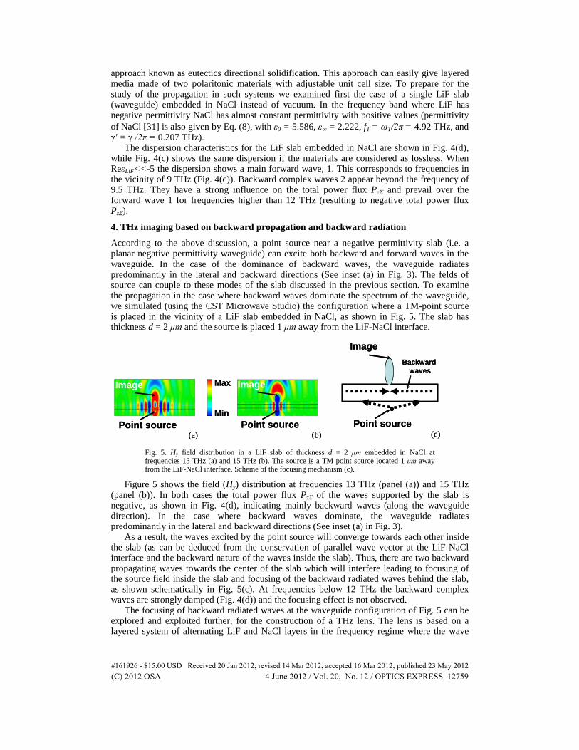
According to the above discussion, a point source near a negative permittivity slab (i.e. a planar negative permittivity waveguide) can excite both backward and forward waves in the waveguide. In the case of the dominance of backward waves, the waveguide radiates predominantly in the lateral and backward directions (See inset (a) in Fig. 3). The felds of source can couple to these modes of the slab discussed in the previous section. To examine the propagation in the case where backward waves dominate the spectrum of the waveguide, we simulated (using the CST Microwave Studio) the configuration where a TM-point source is placed in the vicinity of a LiF slab embedded in NaCl, as shown in Fig. 5. The slab has thickness d = 2 μm and the source is placed 1 μm away from the LiF-NaCl interface.
Max
MinPoint source
Image
Point source
Image
Point source
ImageBackward
waves
(a) (b) (c)
Max
MinPoint source
Image
Point source
Image
Point source
ImageBackward
waves
(a) (b) (c)
Fig. 5. Hy field distribution in a LiF slab of thickness d = 2 μm embedded in NaCl at frequencies 13 THz (a) and 15 THz (b). The source is a TM point source located 1 μm away from the LiF-NaCl interface. Scheme of the focusing mechanism (c).
Figure 5 shows the field (Hy) distribution at frequencies 13 THz (panel (a)) and 15 THz (panel (b)). In both cases the total power flux PzΣ of the waves supported by the slab is negative, as shown in Fig. 4(d), indicating mainly backward waves (along the waveguide direction). In the case where backward waves dominate, the waveguide radiates predominantly in the lateral and backward directions (See inset (a) in Fig. 3).
As a result, the waves excited by the point source will converge towards each other inside the slab (as can be deduced from the conservation of parallel wave vector at the LiF-NaCl interface and the backward nature of the waves inside the slab). Thus, there are two backward propagating waves towards the center of the slab which will interfere leading to focusing of the source field inside the slab and focusing of the backward radiated waves behind the slab, as shown schematically in Fig. 5(c). At frequencies below 12 THz the backward complex waves are strongly damped (Fig. 4(d)) and the focusing effect is not observed.
The focusing of backward radiated waves at the waveguide configuration of Fig. 5 can be explored and exploited further, for the construction of a THz lens. The lens is based on a layered system of alternating LiF and NaCl layers in the frequency regime where the wave
#161926 - $15.00 USD Received 20 Jan 2012; revised 14 Mar 2012; accepted 16 Mar 2012; published 23 May 2012(C) 2012 OSA 4 June 2012 / Vol. 20, No. 12 / OPTICS EXPRESS 12759
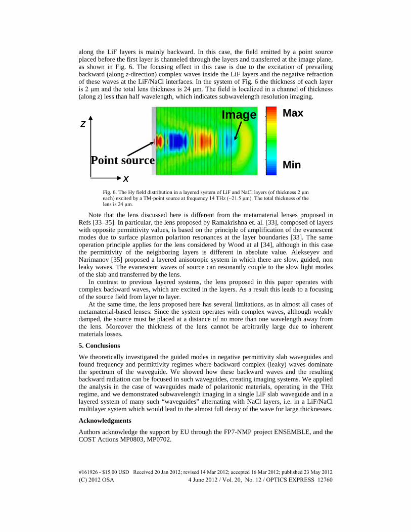
along the LiF layers is mainly backward. In this case, the field emitted by a point source placed before the first layer is channeled through the layers and transferred at the image plane, as shown in Fig. 6. The focusing effect in this case is due to the excitation of prevailing backward (along z-direction) complex waves inside the LiF layers and the negative refraction of these waves at the LiF/NaCl interfaces. In the system of Fig. 6 the thickness of each layer is 2 μm and the total lens thickness is 24 μm. The field is localized in a channel of thickness (along z) less than half wavelength, which indicates subwavelength resolution imaging.
Point source
Max
Min
z
x
z
x
Image
Fig. 6. The Hy field distribution in a layered system of LiF and NaCl layers (of thickness 2 μm each) excited by a TM-point source at frequency 14 THz (~21.5 μm). The total thickness of the lens is 24 μm.
Note that the lens discussed here is different from the metamaterial lenses proposed in Refs [33–35]. In particular, the lens proposed by Ramakrishna et. al. [33], composed of layers with opposite permittivity values, is based on the principle of amplification of the evanescent modes due to surface plasmon polariton resonances at the layer boundaries [33]. The same operation principle applies for the lens considered by Wood at al [34], although in this case the permittivity of the neighboring layers is different in absolute value. Alekseyev and Narimanov [35] proposed a layered anisotropic system in which there are slow, guided, non leaky waves. The evanescent waves of source can resonantly couple to the slow light modes of the slab and transferred by the lens.
In contrast to previous layered systems, the lens proposed in this paper operates with complex backward waves, which are excited in the layers. As a result this leads to a focusing of the source field from layer to layer.
At the same time, the lens proposed here has several limitations, as in almost all cases of metamaterial-based lenses: Since the system operates with complex waves, although weakly damped, the source must be placed at a distance of no more than one wavelength away from the lens. Moreover the thickness of the lens cannot be arbitrarily large due to inherent materials losses.
5. Conclusions
We theoretically investigated the guided modes in negative permittivity slab waveguides and found frequency and permittivity regimes where backward complex (leaky) waves dominate the spectrum of the waveguide. We showed how these backward waves and the resulting backward radiation can be focused in such waveguides, creating imaging systems. We applied the analysis in the case of waveguides made of polaritonic materials, operating in the THz regime, and we demonstrated subwavelength imaging in a single LiF slab waveguide and in a layered system of many such “waveguides” alternating with NaCl layers, i.e. in a LiF/NaCl multilayer system which would lead to the almost full decay of the wave for large thicknesses.
Acknowledgments
Authors acknowledge the support by EU through the FP7-NMP project ENSEMBLE, and the COST Actions MP0803, MP0702.
#161926 - $15.00 USD Received 20 Jan 2012; revised 14 Mar 2012; accepted 16 Mar 2012; published 23 May 2012(C) 2012 OSA 4 June 2012 / Vol. 20, No. 12 / OPTICS EXPRESS 12760