Embed Size (px)
Citation preview
RINGSPANN® Registered Trademark of RINGSPANN GmbH, Bad Homburg
88
Backstops
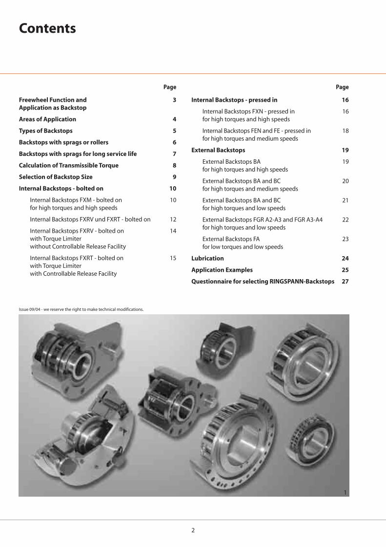
2
1
Contents
Freewheel Function and Application as Backstop
Areas of Application
Types of Backstops
Backstops with sprags or rollers
Backstops with sprags for long service life
Calculation of Transmissible Torque
Selection of Backstop Size
Internal Backstops - bolted on
Internal Backstops FXM - bolted onfor high torques and high speeds
Internal Backstops FXRV und FXRT - bolted on
Internal Backstops FXRV - bolted onwith Torque Limiter without Controllable Release Facility
Internal Backstops FXRT - bolted onwith Torque Limiter with Controllable Release Facility
3
4
5
6
7
8
9
10
10
12
14
15
Page
16
16
18
19
19
20
21
22
23
24
25
27
Page
Internal Backstops - pressed in
Internal Backstops FXN - pressed infor high torques and high speeds
Internal Backstops FEN and FE - pressed infor high torques and medium speeds
External Backstops
External Backstops BAfor high torques and high speeds
External Backstops BA and BCfor high torques and medium speeds
External Backstops BA and BCfor high torques and low speeds
External Backstops FGR A2-A3 and FGR A3-A4for high torques and low speeds
External Backstops FAfor low torques and low speeds
Lubrication
Application Examples
Questionnaire for selecting RINGSPANN-Backstops
Issue 09/04 - we reserve the right to make technical modifications.
3
2
3 4
Freewheel Function and Application as Backstop
Freewheel Function
Freewheels are machine elementswith particular characteristics:
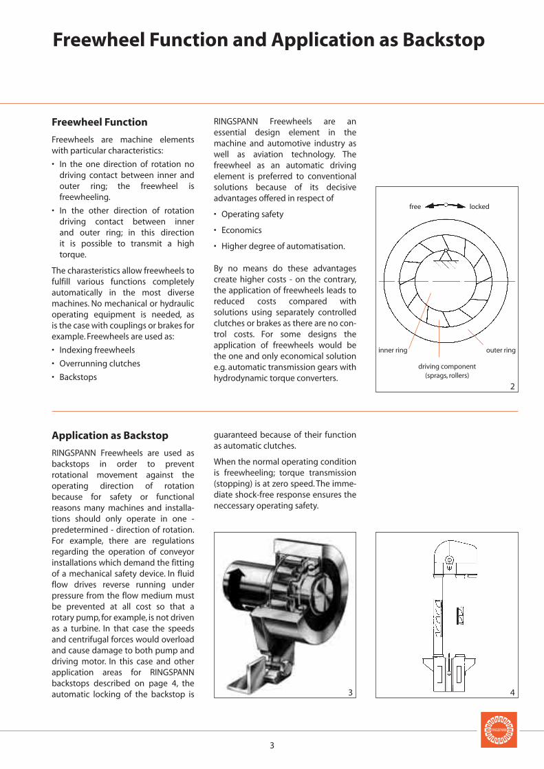
• In the one direction of rotation nodriving contact between inner andouter ring; the freewheel isfreewheeling.
• In the other direction of rotationdriving contact between inner and outer ring; in this direction it is possible to transmit a hightorque.
The charasteristics allow freewheels tofulfill various functions completelyautomatically in the most diversemachines. No mechanical or hydraulicoperating equipment is needed, as is the case with couplings or brakes forexample. Freewheels are used as:
• Indexing freewheels
• Overrunning clutches
• Backstops
RINGSPANN Freewheels are anessential design element in themachine and automotive industry aswell as aviation technology. Thefreewheel as an automatic drivingelement is preferred to conventionalsolutions because of its decisiveadvantages offered in respect of
• Operating safety
• Economics
• Higher degree of automatisation.
By no means do these advantagescreate higher costs - on the contrary,the application of freewheels leads toreduced costs compared withsolutions using separately controlledclutches or brakes as there are no con-trol costs. For some designs theapplication of freewheels would bethe one and only economical solutione.g. automatic transmission gears withhydrodynamic torque converters.
Application as Backstop
RINGSPANN Freewheels are used asbackstops in order to preventrotational movement against theoperating direction of rotationbecause for safety or functionalreasons many machines and installa-tions should only operate in one -predetermined - direction of rotation.For example, there are regulationsregarding the operation of conveyorinstallations which demand the fittingof a mechanical safety device. In fluidflow drives reverse running underpressure from the flow medium mustbe prevented at all cost so that arotary pump, for example, is not drivenas a turbine. In that case the speedsand centrifugal forces would overloadand cause damage to both pump anddriving motor. In this case and otherapplication areas for RINGSPANNbackstops described on page 4, theautomatic locking of the backstop is
guaranteed because of their functionas automatic clutches.
When the normal operating conditionis freewheeling; torque transmission(stopping) is at zero speed. The imme-diate shock-free response ensures theneccessary operating safety.
free locked
outer ringinner ring
driving component(sprags, rollers)
4
6
7
8
5
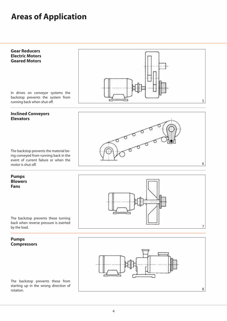
Areas of Application
Inclined ConveyorsElevators
The backstop prevents the material be-ing conveyed from running back in theevent of current failure or when themotor is shut off.
PumpsBlowersFans
The backstop prevents these turningback when reverse pressure is exertedby the load.
Gear ReducersElectric MotorsGeared Motors
In drives on conveyor systems thebackstop prevents the system fromrunning back when shut off.
PumpsCompressors
The backstop prevents these fromstarting up in the wrong direction ofrotation.
5
9
10
11
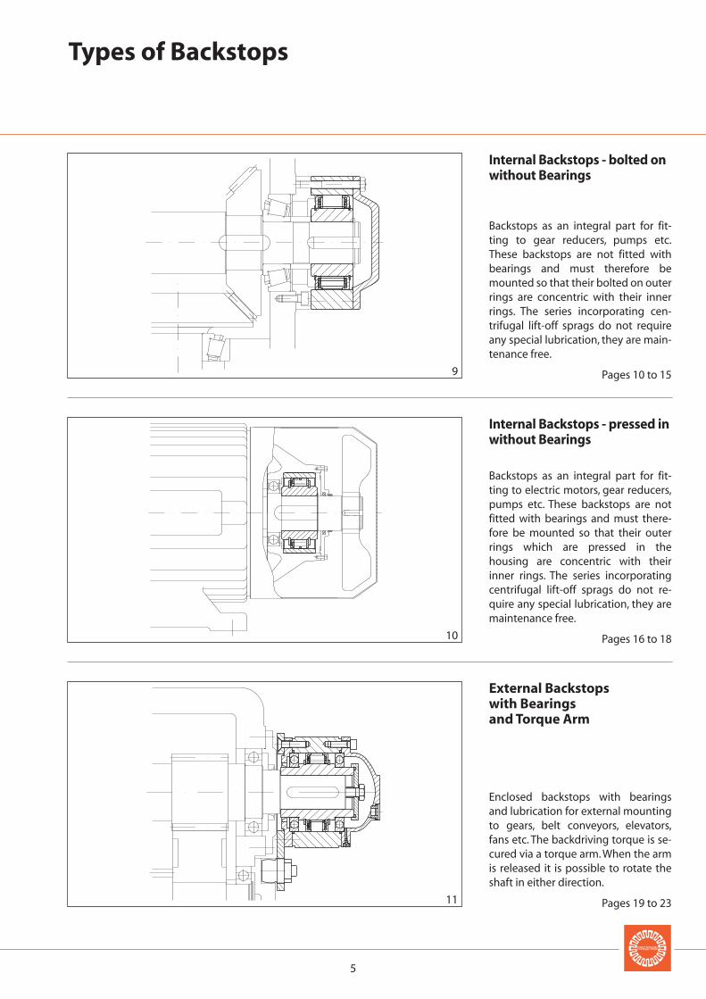
Types of Backstops
Internal Backstops - bolted onwithout Bearings
Backstops as an integral part for fit-ting to gear reducers, pumps etc.These backstops are not fitted withbearings and must therefore bemounted so that their bolted on outerrings are concentric with their innerrings. The series incorporating cen-trifugal lift-off sprags do not requireany special lubrication, they are main-tenance free.
Pages 10 to 15
Internal Backstops - pressed inwithout Bearings
Backstops as an integral part for fit-ting to electric motors, gear reducers,pumps etc. These backstops are notfitted with bearings and must there-fore be mounted so that their outerrings which are pressed in thehousing are concentric with theirinner rings. The series incorporatingcentrifugal lift-off sprags do not re-quire any special lubrication, they aremaintenance free.
Pages 16 to 18
External Backstopswith Bearings and Torque Arm
Enclosed backstops with bearingsand lubrication for external mountingto gears, belt conveyors, elevators,fans etc. The backdriving torque is se-cured via a torque arm. When the armis released it is possible to rotate theshaft in either direction.
Pages 19 to 23
6
12 13
14 15
Backstops with sprags or rollers
two different designs of freewheels
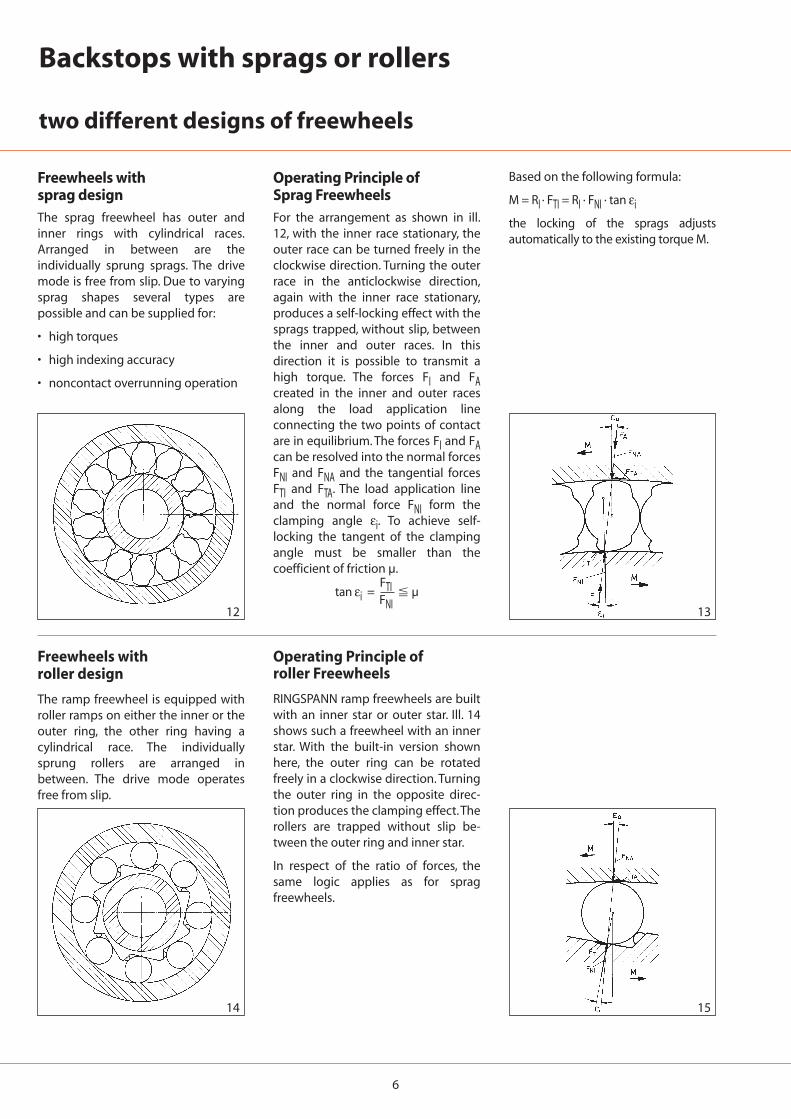
Freewheels with sprag designThe sprag freewheel has outer andinner rings with cylindrical races.Arranged in between are theindividually sprung sprags. The drivemode is free from slip. Due to varyingsprag shapes several types arepossible and can be supplied for:
• high torques
• high indexing accuracy
• noncontact overrunning operation
Operating Principle of Sprag FreewheelsFor the arrangement as shown in ill.12, with the inner race stationary, theouter race can be turned freely in theclockwise direction. Turning the outerrace in the anticlockwise direction,again with the inner race stationary,produces a self-locking effect with thesprags trapped, without slip, betweenthe inner and outer races. In thisdirection it is possible to transmit ahigh torque. The forces FI and FAcreated in the inner and outer racesalong the load application lineconnecting the two points of contactare in equilibrium. The forces FI and FAcan be resolved into the normal forcesFNI and FNA and the tangential forcesFTI and FTA. The load application lineand the normal force FNI form theclamping angle εi. To achieve self-locking the tangent of the clampingangle must be smaller than thecoefficient of friction µ.
tan εi = FTIFNI
� µ
Based on the following formula:
M = RI · FTI = RI · FNI · tan εi
the locking of the sprags adjustsautomatically to the existing torque M.
Freewheels with roller design
The ramp freewheel is equipped withroller ramps on either the inner or theouter ring, the other ring having acylindrical race. The individuallysprung rollers are arranged inbetween. The drive mode operatesfree from slip.
Operating Principle ofroller Freewheels
RINGSPANN ramp freewheels are builtwith an inner star or outer star. Ill. 14shows such a freewheel with an innerstar. With the built-in version shownhere, the outer ring can be rotatedfreely in a clockwise direction. Turningthe outer ring in the opposite direc-tion produces the clamping effect.Therollers are trapped without slip be-tween the outer ring and inner star.
In respect of the ratio of forces, thesame logic applies as for spragfreewheels.
7
16
17
Backstops with sprags for long service life
Locking direction
Freewheeling direction
Inner ring
CageSprag
SupportringOuter ring
Inner ring
CageSprag
SupportringOuter ring
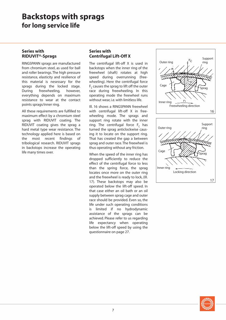
Series withRIDUVIT®-Sprags
RINGSPANN sprags are manufacturedfrom chromium steel, as used for balland roller bearings. The high pressureresistance, elasticity and resilience ofthis material is nesessary for thesprags during the locked stage.During freewheeling, however,everything depends on maximumresistance to wear at the contactpoints sprags/inner ring.
All these requirements are fulfilled tomaximum effect by a chromium steelsprag with RIDUVIT coating. TheRIDUVIT coating gives the sprag ahard metal type wear resistance. Thetechnology applied here is based onthe most recent findings oftribological research. RIDUVIT spragsin backstops increase the operatinglife many times over.
Series withCentrifugal Lift-Off X
The centrifugal lift-off X is used inbackstops when the inner ring of thefreewheel (shaft) rotates at highspeed during overrunning (free-wheeling). Here the centrifugal forceFc causes the sprag to lift off the outerrace during freewheeling. In thisoperating mode the freewheel runswithout wear, i.e. with limitless life.
Ill. 16 shows a RINGSPANN freewheelwith centrifugal lift-off X in free-wheeling mode. The sprags andsupport ring rotate with the innerring. The centrifugal force Fc hasturned the sprag anticlockwise caus-ing it to locate on the support ring.That has created the gap a betweensprag and outer race. The freewheel isthus operating without any friction.
When the speed of the inner ring hasdropped sufficiently to reduce theeffect of the centrifugal force to lessthan the spring force, the spraglocates once more on the outer ringand the freewheel is ready to lock, (Ill.17). These backstops may also beoperated below the lift-off speed. Inthat case either an oil bath or an oilsupply between sprag cage and outerrace should be provided. Even so, thelife under such operating conditionsis limited if no hydrodynamicassistance of the sprags can beachieved. Please refer to us regardinglife expectancy when operatingbelow the lift-off speed by using thequestionnaire on page 27.
8
0 1° 2° 3°0
1 000
2 000
3 000
4 000
5 000
6 000
7 000
8 000
9 000
18
19
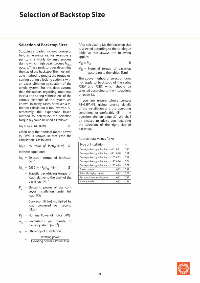
Versuch 4.4 4.6
Messung o +
Theorie
Effort Nr. 4.4 4.6
Detection o +
Theory
Calculation of Transmissible Torque
Transmissible Torque
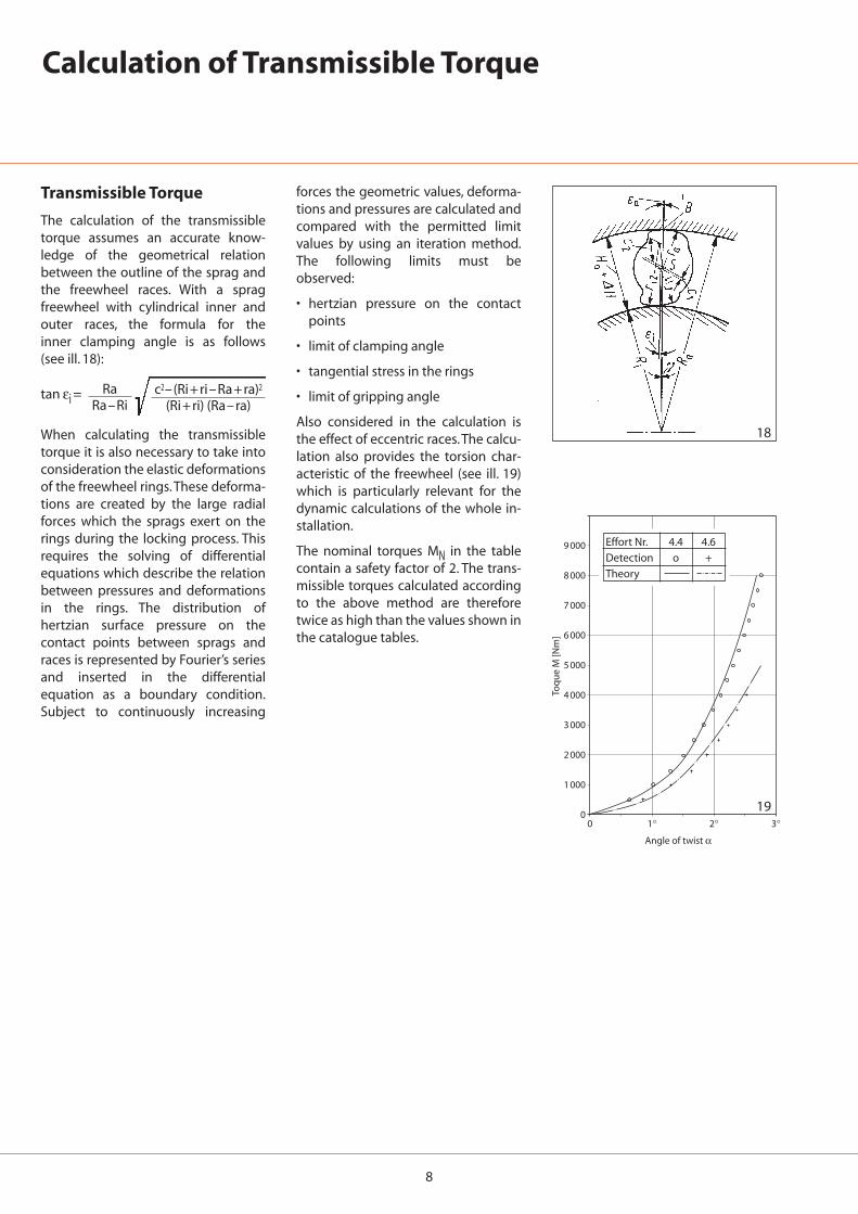
The calculation of the transmissibletorque assumes an accurate know-ledge of the geometrical relationbetween the outline of the sprag andthe freewheel races. With a spragfreewheel with cylindrical inner andouter races, the formula for the inner clamping angle is as follows (see ill. 18):
When calculating the transmissibletorque it is also necessary to take intoconsideration the elastic deformationsof the freewheel rings.These deforma-tions are created by the large radialforces which the sprags exert on therings during the locking process. Thisrequires the solving of differentialequations which describe the relationbetween pressures and deformationsin the rings. The distribution ofhertzian surface pressure on thecontact points between sprags andraces is represented by Fourier’s seriesand inserted in the differentialequation as a boundary condition.Subject to continuously increasing
forces the geometric values, deforma-tions and pressures are calculated andcompared with the permitted limitvalues by using an iteration method.The following limits must beobserved:
• hertzian pressure on the contactpoints
• limit of clamping angle
• tangential stress in the rings
• limit of gripping angle
Also considered in the calculation isthe effect of eccentric races.The calcu-lation also provides the torsion char-acteristic of the freewheel (see ill. 19)which is particularly relevant for thedynamic calculations of the whole in-stallation.
The nominal torques MN in the tablecontain a safety factor of 2. The trans-missible torques calculated accordingto the above method are thereforetwice as high than the values shown inthe catalogue tables.
tan εi =Ra
Ra–Ric2–(Ri+ri–Ra+ra)2
(Ri+ri) (Ra–ra)
Angle of twist α
Toq
ue
M [N
m]
9
Selection of Backstop Size
Selection of Backstop Sizes
Stopping a loaded inclined conveyorbelt, an elevator or, for example apump, is a highly dynamic processduring which high peak torques Mmaxoccurs. These peak torques determinethe size of the backstop. The most reli-able method to predict the torque oc-curring during a locking action is withan exact vibration calculation of thewhole system. But this does assumethat the factors regarding rotationalinertia and spring stiffness etc. of thevarious elements of the system areknown. In many cases, however, a vi-bration calculation is too involved. Al-ternatively, the experience basedmethod to determine the selectiontorque MA could be used, as follows:
MA = 1,75 · ML [Nm] (1)
Often only the nominal motor powerP0 [kW] is known. In that case thecalculation is as follows:
MA = 1,75 · 9550 · �2 · P0/nsp [Nm] (2)
In these equations:
MA = Selection torque of backstop[Nm]
ML = 9550 · � · PL/nsp [Nm] (3)
= Statistic backdriving torque ofload relative to the shaft of thebackstop [Nm]
PL = Elevating power of the con-veyor installation under fullload [kW]
= Conveyor lift [m] multiplied byload conveyed per second[kN/s]
P0 = Nominal Power of motor [kW]
nsp = Revolutions per minute ofbackstop shaft [min-1]
� = Efficiency of installation
Elevating power=
Elevating power + Power loss
After calculating MA the backstop sizeis selected according to the cataloguetable so that always the followingapplies:
MN � MA (4)
MN = Nominal torque of backstopaccording to the tables [Nm]
The above method of selection doesnot apply to backstops of the seriesFXRV and FXRT; which should beselected according to the instructionson page 13.
If you are unsure, please contactRINGSPANN, giving precise details of the installation and the operatingconditions or preferably fill in thequestionnaire on page 27. We shall be pleased to advise you regardingthe selection of the right size ofbackstop.
Approximate values for �:
Type of Installation � �2
Conveyor belts, gradient up to 6° 0,71 0,50
Conveyor belts, gradient up to 8° 0,78 0,61
Conveyor belts, gradient up to 10° 0,83 0,69
Conveyor belts, gradient up to 12° 0,86 0,74
Conveyor belts, gradient up to 15° 0,89 0,79
Screw pumps 0,93 0,87
Ball mills, drying drums 0,85 0,72
Bucket conveyors, elevators 0,92 0,85
Hammer mills 0,93 0,87
10
20
FXM 31 - 17 DX 4867.031.200 100 100 95 – – – – 890 5 000FXM 38 - 17 DX 4867.038.200 150 140 130 – – – – 860 5 000FXM 46 - 25 DX 4867.046.200 390 380 350 – – – – 820 5 000
FXM 51 - 25 DX 4867.051.200 480 470 420 – – – – 750 5 000FXM 56 - 25 DX 4867.056.200 580 570 490 – – – – 730 5 000FXM 61 - 19 DX 4867.061.200 420 410 370 – – – – 750 5 000
FXM 66 - 25 DX 4867.066.200 800 780 700 – – – – 700 5 000FXM 76 - 25 DX 4867.076.200 1 050 1 040 890 – – – – 670 5 000FXM 86 - 25 DX 4867.086.200 1 350 1 300 1 030 – – – – 630 5 000
FXM 101 - 25 DX 4867.101.200 1 700 1 600 1 400 – – – – 610 5 000FXM 85 - 40 SX 4867.085.501 1 900 1 900 1 800 1 800 1 700 1 600 – 430 6 000FXM 100 - 40 SX 4867.100.501 2 700 2 600 2 500 2 400 2 200 2 000 – 400 4 500
FXM 120 - 50 SX 4867.120.501 6 500 6 300 5 800 4 800 4 400 3 600 – 320 4 000FXM 140 - 50 SX 4867.140.502 8 700 8 500 7 900 6 700 5 500 5 400 – 320 3 000FXM 170 - 63 SX 4867.170.502 20 000 19 000 16 000 14 000 13 000 12 000 – 250 2 700
FXM 200 - 63 SX 4867.200.501 26 000 23 000 20 500 17 500 15 500 14 000 – 240 2 100FXM 240 - 63 UX 4867.240.501 31 000 30 500 30 000 29 000 26 000 24 000 19 500 220 3 000FXM 240 - 96 UX 4867.240.502 52 050 51 000 49 000 47 500 46 000 44 000 35 000 220 2 500
FXM 260 - 63 UX 4867.260.501 38 500 38 000 37 000 36 500 33 000 29 000 25 000 210 2 500FXM 290 - 70 UX 4867.290.501 59 500 59 000 56 000 50 000 47 000 45 000 37 000 200 2 500FXM 290 - 96 UX 4867.290.502 91 000 90 000 82 500 77 500 70 000 62 500 55 000 200 2 500
FXM 310 - 70 UX 4867.310.500 69 000 68 000 64 500 60 000 55 000 49 000 43 000 195 2 500FXM 310 - 96 UX 4867.310.501 107 000 105 000 99 000 85 500 81 000 74 000 68 000 195 2 100FXM 320 - 70 UX 4867.320.500 76 500 73 000 67 000 62 000 56 500 49 500 43 000 195 2 000
FXM 360 - 100 UX 4867.360.500 149 000 139 500 128 000 119 500 103 500 90 000 80 500 180 1 800FXM 410 - 100 UX 4867.410.500 193 000 179 500 167 000 154 500 137 000 121 500 111 500 170 1 500FXM 2.410 - 100 UX 4867.410.100 364 000 350 000 315 000 296 500 277 500 266 000 223 500 210 1 500
Type Art. no. Theo. nominal Nominal torques MN at existing run out T.I.R. Lift-off Max.torque speed speed
Nm Nm Nm Nm Nm Nm Nm min-1 min-1
Internal Backstops FXM - bolted onfor high torques und high speeds
with sprags and centrifugal lift-off X
➚ 0,8 A➚ 0,5 A➚ 0,4 A➚ 0,3 A➚ 0,2 A➚ 0,1 A➚ 0 A
The maximum transmissible torque is twice the shown torque. Therefore, the peak torque should not exceed twice the nominal torque. The theoretical torque pre-sumes perfect concentricity between inner and outer ring. In practice the concentricity is affected by bearing play and concentricity errors of the adjacent parts.Thenthe nominal torques in the table apply which take into consideration the existing T.l.R. Higher speeds on request.
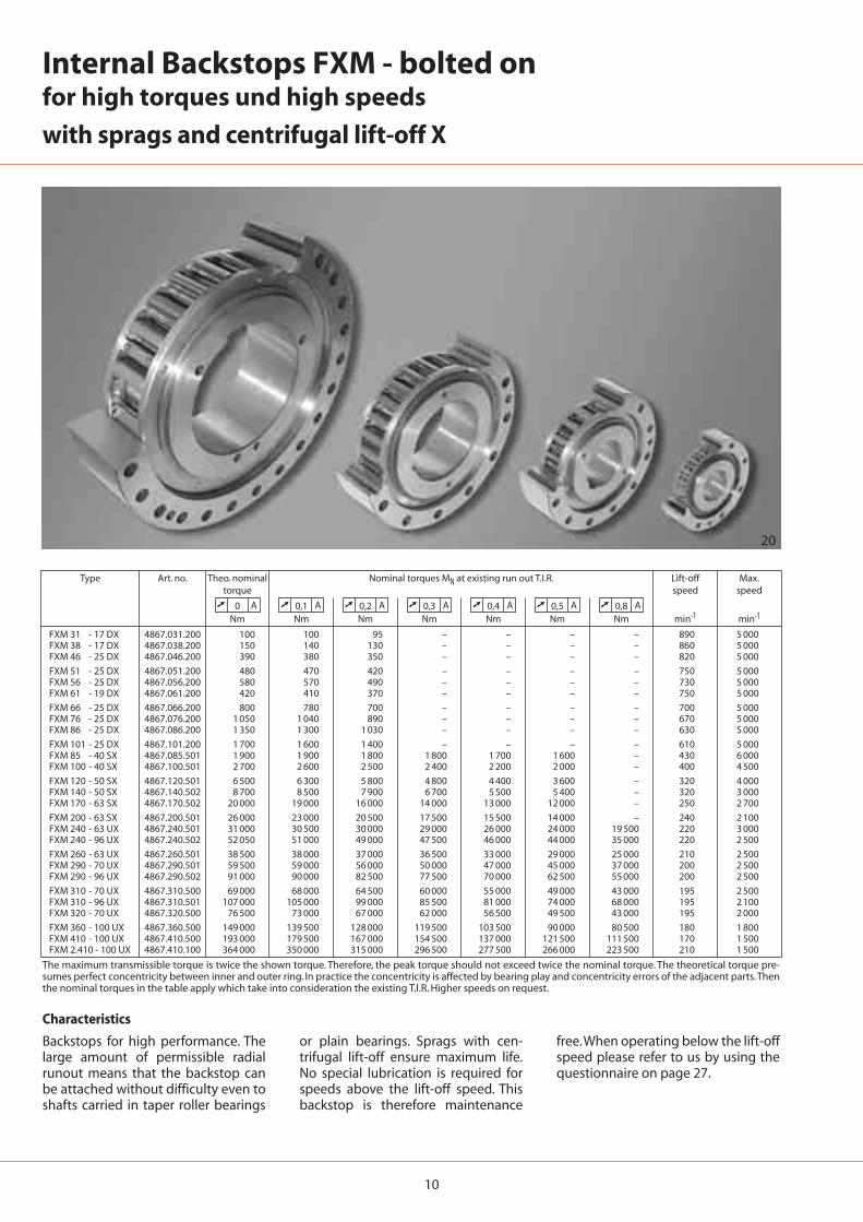
Characteristics
Backstops for high performance. Thelarge amount of permissible radialrunout means that the backstop canbe attached without difficulty even toshafts carried in taper roller bearings
or plain bearings. Sprags with cen-trifugal lift-off ensure maximum life.No special lubrication is required forspeeds above the lift-off speed. Thisbackstop is therefore maintenance
free.When operating below the lift-offspeed please refer to us by using thequestionnaire on page 27.
11
FXM 31 - 17 DX 20* – – – – – 20* 17 25 85 41 55 M6 31 24 1 70 15 6 21 6FXM 38 - 17 DX 25* – – – – – 25* 17 25 90 48 62 M6 38 24 1 75 15 6 21 6FXM 46 - 25 DX 25 – – – – – 30 25 35 95 56 70 M6 46 35 1 82 15 6 21 6
FXM 51 - 25 DX 25 30 35 – – – 36 25 35 105 62 75 M6 51 35 1 90 15 6 21 6FXM 56 - 25 DX 35 – – – – – 40 25 35 110 66 80 M6 56 35 1 96 15 6 21 8FXM 61 - 19 DX 30 35 40 – – – 45* 19 27 120 74 85 M8 61 25 1 105 15 6 21 6
FXM 66 - 25 DX 35 40 45 – – – 48* 25 35 132 82 90 M8 66 35 1 115 15 8 23 8FXM 76 - 25 DX 45 55 – – – – 60* 25 35 140 92 100 M8 76 35 1 125 15 8 23 8FXM 86 - 25 DX 40 45 50 60 65 – 70* 25 40 150 102 110 M8 86 40 1 132 15 8 23 8
FXM 101 - 25 DX 55 70 – – – – 80* 25 50 175 117 125 M10 101 50 1 155 20 8 28 8FXM 85 - 40 SX 45 50 60 65 – – 65 40 50 175 102 125 M10 85 60 1 155 20 8 28 8FXM 100 - 40 SX 45 50 55 60 70 75 80* 40 50 190 130 140 M10 100 60 1.5 165 25 10 35 12
FXM 120 - 50 SX 60 65 70 75 80 95 95 50 60 210 150 160 M10 120 70 1.5 185 25 10 35 12FXM 140 - 50 SX 65 90 100 110 – – 110 50 70 245 170 180 M12 140 70 2 218 25 12 35 12FXM 170 - 63 SX 70 85 90 100 120 – 130 63 80 290 200 210 M16 170 80 2 258 28 12 38 12
FXM 200 - 63 SX 130 – – – – – 155 63 80 310 230 240 M16 200 80 2 278 32 12 42 12FXM 240 - 63 UX – – – – – – 185 63 80 400 280 310 M20 240 90 2 360 48 12 60 12FXM 240 - 96 UX – – – – – – 185 96 125 420 280 310 M24 240 120 2 370 48 15 60 16
FXM 260 - 63 UX – – – – – – 205 63 80 430 300 330 M20 260 105 2 380 48 18 60 16FXM 290 - 70 UX – – – – – – 230 70 80 460 330 360 M20 290 105 2 410 48 18 60 16FXM 290 - 96 UX – – – – – – 230 96 110 460 330 360 M20 290 120 2 410 48 18 60 16
FXM 310 - 70 UX – – – – – – 240 70 125 497 360 380 M20 310 110 3 450 48 18 60 24FXM 310 - 96 UX – – – – – – 240 96 125 497 360 380 M20 310 120 3 450 48 18 60 24FXM 320 - 70 UX – – – – – – 250 70 80 490 360 390 M24 320 105 3 440 55 20 68 16
FXM 360 - 100 UX – – – – – – 280 100 120 540 400 430 M24 360 125 3 500 55 20 68 24FXM 410 - 100 UX – – – – – – 320 100 120 630 460 480 M24 410 125 3 560 55 20 68 24FXM 2.410 - 100 UX – – – – – – 320 200 220 630 460 480 M30 410 220 3 560 55 20 68 24
øJøDB
H7
ød
L
W
V
U
øD øTøTA
øEmin. 3
x30°P
øF
A
➚ . A
min. 2
2221
Type Bore d A B D E F G J L P T U V W Zstandard
max. min.
mm mm mm mm mm mm mm mm mm mm mm mm mm mm mm mm mm mm mm
Internal Backstops FXM - bolted onfor high torques and high speeds
with sprags and centrifugal lift-off X
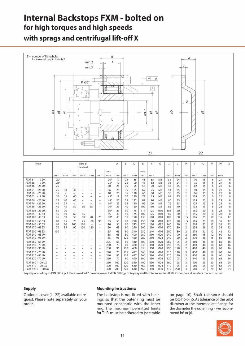
Supply
Optional cover (ill. 22) available on re-quest. Please note separately on yourorder.
Mounting Instructions:
The backstop is not fitted with bear-ings so that the outer ring must bemounted concentric with the innerring. The maximum permitted limitsfor T.l.R. must be adhered to (see table
on page 10). Shaft tolerance shouldbe ISO h6 or j6. As tolerance of the pilotdiameter at the intermediate flange forthe diameter the outer ring F we recom-mend h6 or j6.
Keyway according to DIN 6885, p. 1. Bores marked * have keyways to DIN 6885, p. 3. Keyway width: tolerance class IT10. Other bore diameters made to order.
Z = number of fixing holes for screws G on pitch circle T
12
23
Internal Backstops FXRV and FXRT - bolted onwith Torque Limiter
with or without Controllable Release Facility
Backstop with Torque Limiter
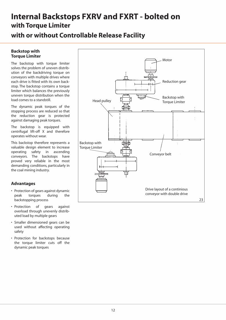
The backstop with torque limitersolves the problem of uneven distrib-ution of the backdriving torque onconveyors with multiple drives whereeach drive is fitted with its own back-stop. The backstop contains a torquelimiter which balances the previouslyuneven torque distribution when theload comes to a standstill.
The dynamic peak torques of thestopping process are reduced so thatthe reduction gear is protectedagainst damaging peak torques.
The backstop is equipped withcentrifugal lift-off X and thereforeoperates without wear.
This backstop therefore represents avaluable design element to increaseoperating safety in ascendingconveyors. The backstops haveproved very reliable in the mostdemanding conditions, particularly inthe coal mining industry.
Advantages
• Protection of gears against dynamicpeak torques during thebackstopping process
• Protection of gears againstoverload through unevenly distrib-uted load by multiple gears
• Smaller dimensioned gears can beused without affecting operatingsafety
• Protection for backstops becausethe torque limiter cuts off thedynamic peak torques
Motor
Reduction gear
Backstop with Torque Limiter
Backstop with Torque Limiter
Head pulley
Conveyor belt
Drive layout of a continious conveyor with double drive
13
Series FXRV Internal Backstop withTorque Limiter withoutControllable Release Facility
This series of backstops with torquelimiter is the simpler design. Theconstruction and available standardsizes are shown on page 14.
Series FXRTInternal Backstop withTorque Limiter withControllable Release Facility
Designed like the series FXRV but withthe addition of a finely controllablerelease mechanism. See page 15 forthe description of the design andfunction of the release mechanismand the standard sizes available.
The backstops with controllablerelease facility are used when acontrolled relaxing of the conveyorbelt tension or of the installation isrequired - perhaps in the case ofjamming at a non - drive drum or for alimited reverse movement of theconveyor installation at low speed.
Selection of Backstop Size
Provided the backdriving torque ML isknown, the backstop is then selectedas follows:
MA = 1,2 · ML [Nm] (5)
If only the nominal motor power P0[kW] is known, the backstop isselected as follows:
MA= 1,2 · 9550 · �2 · P0/nsp [Nm] (6)
In equations 5 and 6 are:
MA = Selection torque of backstopFXRV or FXRT [Nm]
ML = 9550 · � · PL/nsp [Nm]
= Static backdriving torque ofload in relation to backstopshaft [Nm]
PL = Elevating power of conveyor in-stallation at full load [kW]
= Conveyor lift [m] multiplied byload conveyed per second[kN/s]
P0 = Nominal motor power [kW]
nsp = Revolutions per minute ofbackstop shaft [min-1]
� = Efficiency of installation
Elevating power=
Elevating power + Power loss
After calculating MA the backstopshould be selected according to thecatalogue tables so that the followingalways applies:
MR � MA
MR = Max slipping torque of thebackstop acoording to tableson page 14 and 15 [Nm]
Approximate values for �:
Where an application incorporatesmulti-drives, fitting backstops withtorque limiter assumes an even distri-bution of load to all the backstops.Although the static backdrivingtorque of the installation (even withoverload) must never reach the pro-portionate slipping torque of the indi-vidual backstops. The torques listed inthe tables represent maximum values.Lower values can be set on request.
If you are unsure, please contactRINGSPANN, giving precise details ofthe installation and the operating con-ditions or preferably fill in the ques-tionnaire on page 27.
Type of Installation � �2
Conveyor belts, gradient up to 6° 0,71 0,50
Conveyor belts, gradient up to 8° 0,78 0,61
Conveyor belts, gradient up to 10° 0,83 0,69
Conveyor belts, gradient up to 12° 0,86 0,74
Conveyor belts, gradient up to 15° 0,89 0,79
Screw pumps 0,93 0,87
Ball mills, drying drums 0,85 0,72
Bucket conveyors, elevators 0,92 0,85
Hammer mills 0,93 0,87
14
max
H7
A
➚ 0,25 A 2
ødøS
øU
H7 j6
øRøT
+2
øA øD
O
H±0,1C
L
K
1
3
øE
M
min
øU
24
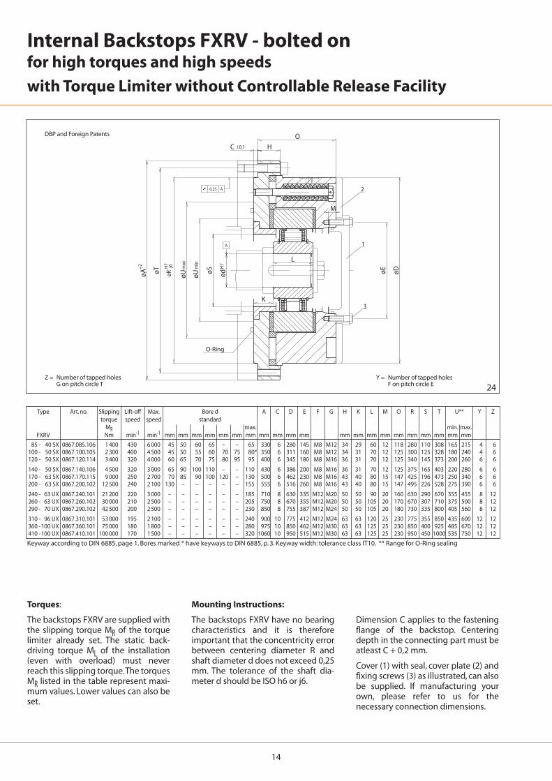
85 - 40 SX 0867.085.106 1 400 430 6 000 45 50 60 65 – – 65 330 6 280 145 M8 M12 34 29 60 12 118 280 110 308 165 215 4 6100 - 50 SX 0867.100.105 2 300 400 4 500 45 50 55 60 70 75 80* 350 6 311 160 M8 M12 34 31 70 12 125 300 125 328 180 240 4 6120 - 50 SX 0867.120.114 3 400 320 4 000 60 65 70 75 80 95 95 400 6 345 180 M8 M16 36 31 70 12 125 340 145 373 200 260 6 6
140 - 50 SX 0867.140.106 4 500 320 3 000 65 90 100 110 – – 110 430 6 386 200 M8 M16 36 31 70 12 125 375 165 403 220 280 6 6170 - 63 SX 0867.170.115 9 000 250 2 700 70 85 90 100 120 – 130 500 6 462 230 M8 M16 43 40 80 15 147 425 196 473 250 340 6 6200 - 63 SX 0867.200.102 12 500 240 2 100 130 – – – – – 155 555 6 516 260 M8 M16 43 40 80 15 147 495 226 528 275 390 6 6
240 - 63 UX 0867.240.101 21 200 220 3 000 – – – – – – 185 710 8 630 335 M12 M20 50 50 90 20 160 630 290 670 355 455 8 12260 - 63 UX 0867.260.102 30 000 210 2 500 – – – – – – 205 750 8 670 355 M12 M20 50 50 105 20 170 670 307 710 375 500 8 12290 - 70 UX 0867.290.102 42 500 200 2 500 – – – – – – 230 850 8 755 387 M12 M24 50 50 105 20 180 730 335 800 405 560 8 12
310 - 96 UX 0867.310.101 53 000 195 2 100 – – – – – – 240 900 10 775 412 M12 M24 63 63 120 25 230 775 355 850 435 600 12 12360 -100 UX 0867.360.101 75 000 180 1 800 – – – – – – 280 975 10 850 462 M12 M30 63 63 125 25 230 850 400 925 485 670 12 12410 -100 UX 0867.410.101 100 000 170 1 500 – – – – – – 320 1060 10 950 515 M12 M30 63 63 125 25 230 950 450 1000 535 750 12 12
Internal Backstops FXRV - bolted onfor high torques and high speeds
with Torque Limiter without Controllable Release Facility
Type Art. no. Slipping Lift-off Max. Bore d A C D E F G H K L M O R S T U** Y Ztorque speed speed standard
MR max. min. max.FXRV Nm min-1 min-1 mm mm mm mm mm mm mm mm mm mm mm mm mm mm mm mm mm mm mm mm mm
Keyway according to DIN 6885, page 1. Bores marked * have keyways to DIN 6885, p. 3. Keyway width: tolerance class IT10. ** Range for O-Ring sealing
Mounting Instructions:
The backstops FXRV have no bearingcharacteristics and it is thereforeimportant that the concentricity errorbetween centering diameter R andshaft diameter d does not exceed 0,25mm. The tolerance of the shaft dia-meter d should be ISO h6 or j6.
Torques:
The backstops FXRV are supplied withthe slipping torque MR of the torquelimiter already set. The static back-driving torque ML of the installation(even with overload) must neverreach this slipping torque.The torquesMR listed in the table represent maxi-mum values. Lower values can also beset.
Dimension C applies to the fasteningflange of the backstop. Centeringdepth in the connecting part must beatleast C + 0,2 mm.
Cover (1) with seal, cover plate (2) andfixing screws (3) as illustrated, can alsobe supplied. If manufacturing yourown, please refer to us for thenecessary connection dimensions.
O-Ring
DBP and Foreign Patents
Z = Number of tapped holes G on pitch circle T
Y = Number of tapped holes F on pitch circle E
15
H7 j6 max
H7
W
A
➚ 0,25 A
7 5
4
6
ødøSøUøRøT
+2
øA øD
O
H±0,1C
L
K
B
N
Vm
inøU
25 26
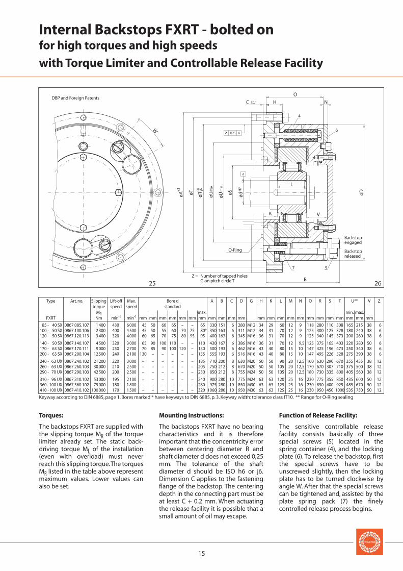
85 - 40 SX 0867.085.107 1 400 430 6 000 45 50 60 65 – – 65 330 151 6 280 M12 34 29 60 12 9 118 280 110 308 165 215 38 6100 - 50 SX 0867.100.106 2 300 400 4 500 45 50 55 60 70 75 80* 350 163 6 311 M12 34 31 70 12 9 125 300 125 328 180 240 38 6120 - 50 SX 0867.120.113 3 400 320 4 000 60 65 70 75 80 95 95 400 163 6 345 M16 36 31 70 12 9 125 340 145 373 200 260 38 6
140 - 50 SX 0867.140.107 4 500 320 3 000 65 90 100 110 – – 110 430 167 6 386 M16 36 31 70 12 9,5 125 375 165 403 220 280 50 6170 - 63 SX 0867.170.111 9 000 250 2 700 70 85 90 100 120 – 130 500 193 6 462 M16 43 40 80 15 10 147 425 196 473 250 340 38 6200 - 63 SX 0867.200.104 12 500 240 2 100 130 – – – – – 155 555 193 6 516 M16 43 40 80 15 10 147 495 226 528 275 390 38 6
240 - 63 UX 0867.240.102 21 200 220 3 000 – – – – – – 185 710 200 8 630 M20 50 50 90 20 12,5 160 630 290 670 355 455 38 12260 - 63 UX 0867.260.103 30 000 210 2 500 – – – – – – 205 750 212 8 670 M20 50 50 105 20 12,5 170 670 307 710 375 500 38 12290 - 70 UX 0867.290.103 42 500 200 2 500 – – – – – – 230 850 212 8 755 M24 50 50 105 20 12,5 180 730 335 800 405 560 38 12
310 - 96 UX 0867.310.102 53 000 195 2 100 – – – – – – 240 900 280 10 775 M24 63 63 120 25 16 230 775 355 850 435 600 50 12360 -100 UX 0867.360.102 75 000 180 1 800 – – – – – – 280 975 280 10 850 M30 63 63 125 25 16 230 850 400 925 485 670 50 12410 -100 UX 0867.410.102 100 000 170 1 500 – – – – – – 320 1060 280 10 950 M30 63 63 125 25 16 230 950 450 1000 535 750 50 12
DBP and Foreign Patents
Z = Number of tapped holes G on pitch circle T
Backstopengaged
Backstopreleased
O-Ring
Internal Backstops FXRT - bolted onfor high torques and high speeds
with Torque Limiter and Controllable Release Facility
Type Art. no. Slipping Lift-off Max. Bore d A B C D G H K L M N O R S T U** V Ztorque speed speed standard
MR max. min. max.FXRT Nm min-1 min-1 mm mm mm mm mm mm mm mm mm mm mm mm mm mm mm mm mm mm mm mm mm mm mm
Keyway according to DIN 6885, page 1. Bores marked * have keyways to DIN 6885, p. 3. Keyway width: tolerance class IT10. ** Range for O-Ring sealing
Mounting Instructions:
The backstops FXRT have no bearingcharacteristics and it is thereforeimportant that the concentricity errorbetween centering diameter R andshaft diameter d does not exceed 0,25mm. The tolerance of the shaftdiameter d should be ISO h6 or j6.Dimension C applies to the fasteningflange of the backstop. The centeringdepth in the connecting part must beat least C + 0,2 mm. When actuatingthe release facility it is possible that asmall amount of oil may escape.
Torques:
The backstops FXRT are supplied withthe slipping torque MR of the torquelimiter already set. The static back-driving torque ML of the installation(even with overload) must neverreach this slipping torque.The torquesMR listed in the table above representmaximum values. Lower values canalso be set.
Function of Release Facility:
The sensitive controllable releasefacility consists basically of threespecial screws (5) located in thespring container (4), and the lockingplate (6). To release the backstop, firstthe special screws have to beunscrewed slightly, then the lockingplate has to be turned clockwise byangle W. After that the special screwscan be tightened and, assisted by theplate spring pack (7) the finelycontrolled release process begins.
16
FXN 31 - 17 DX/ 60 4867.031.127 100 100 95 – – – 890 5 000FXN 31 - 17 DX/ 62 4867.031.128 100 100 95 – – – 890 5 000FXN 38 - 17 DX/ 70 4867.038.103 150 140 130 – – – 860 5 000
FXN 46 - 25 DX/ 80 4867.046.101 390 380 350 – – – 820 5 000FXN 51 - 25 DX/ 85 4867.051.112 480 470 420 – – – 750 5 000FXN 56 - 25 DX/ 90 4867.056.105 580 570 490 – – – 730 5 000
FXN 61 - 19 DX/ 95 4867.061.140 420 410 370 – – – 750 5 000FXN 61 - 19 DX/106 4867.061.135 420 410 370 – – – 750 5 000FXN 66 - 25 DX/100 4867.066.208 800 780 700 – – – 700 5 000
FXN 66 - 25 DX/110 4867.066.209 800 780 700 – – – 700 5 000FXN 76 - 25 DX/115 4867.076.112 1 050 1 040 890 – – – 670 5 000FXN 76 - 25 DX/120 4867.076.105 1 050 1 040 890 – – – 670 5 000
FXN 86 - 25 DX/125 4867.086.205 1 350 1 300 1 030 – – – 630 5 000FXN 86 - 25 DX/130 4867.086.207 1 350 1 300 1 030 – – – 630 5 000FXN 101 - 25 DX/140 4867.101.204 1 700 1 600 1 400 – – – 610 5 000
FXN 101 - 25 DX/149 4867.101.208 1 700 1 600 1 400 – – – 610 5 000FXN 101 - 25 DX/150 4867.101.205 1 700 1 600 1 400 – – – 610 5 000FXN 85 - 40 SX/140 4867.085.111 1 900 1 900 1 800 1 800 1 700 1 600 430 6 000
FXN 85 - 40 SX/150 4867.085.112 1 900 1 900 1 800 1 800 1 700 1 600 430 6 000FXN 100 - 40 SX/160 4867.100.110 2 700 2 600 2 500 2 400 2 200 2 000 400 4 500FXN 105 - 50 SX/165 4867.105.105 4 000 3 800 3 500 3 300 2 900 2 800 380 4 500
FXN 120 - 50 SX/198 4867.120.516 6 500 6 300 5 800 4 800 4 400 3 600 320 4 000FXN 170 - 63 SX/258 4867.170.508 20 000 19 000 16 000 14 000 13 000 12 000 250 2 700
27
Type Art. no. Theor. Nominal Nominal torque MN at existing run out T.I.R. Lift-off Max.torque speed speed
Nm Nm Nm Nm Nm Nm min-1 min-1
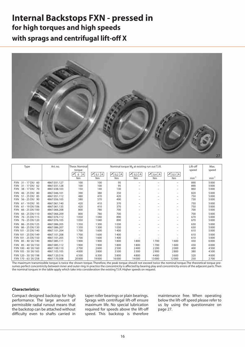
Internal Backstops FXN - pressed in for high torques and high speeds
with sprags and centrifugal lift-off X
The maximum transmissible torque is twice the shown torque. Therefore, the peak torque should not exceed twice the nominal torque.The theoretical torque pre-sumes perfect concentricity between inner and outer ring. In practice the concentricity is affected by bearing play and concentricity errors of the adjacent parts.Thenthe nominal torques in the table apply which take into consideration the existing T.l.R. Hiqher speeds on request.
Characteristics:
Compact designed backstop for highperformance. The large amount ofpermissible radial runout means thatthe backstop can be attached withoutdifficulty even to shafts carried in
taper roller bearings or plain bearings.Sprags with centrifugal lift-off ensuremaximum life. No special lubricationrequired for speeds above the lift-offspeed. This backstop is therefore
maintenance free. When operatingbelow the lift-off speed please refer tous by using the questionnaire onpage 27.
➚ 0 A ➚ 0,1 A ➚ 0,2 A ➚ 0,3 A ➚ 0,4 A ➚ 0,5 A
17
FXN 31 - 17 DX/ 60 20* – – – – – 20* 17 25 60 P6 55 31 85 24FXN 31 - 17 DX/ 62 20* – – – – – 20* 17 25 62 P6 55 31 85 24FXN 38 - 17 DX/ 70 25* – – – – – 25* 17 25 70 P6 62 38 90 24FXN 46 - 25 DX/ 80 25 – – – – – 30 25 35 80 P6 70 46 95 35FXN 51 - 25 DX/ 85 25 30 35 – – – 36 25 35 85 P6 75 51 105 35FXN 56 - 25 DX/ 90 35 – – – – – 40 25 35 90 P6 80 56 110 35FXN 61 - 19 DX/ 95 30 35 40 – – – 45* 19 26 95 P6 85 61 120 25FXN 61 - 19 DX/106 30 35 40 – – – 45* 19 25 106 H7 85 61 120 25FXN 66 - 25 DX/100 35 40 45 – – – 48* 25 30 100 P6 90 66 132 35FXN 66 - 25 DX/110 35 40 45 – – – 48* 25 40 110 P6 90 66 132 35FXN 76 - 25 DX/115 45 55 – – – – 60* 25 40 115 P6 100 76 140 35FXN 76 - 25 DX/120 45 55 – – – – 60* 25 32 120 J6 100 76 140 35FXN 86 - 25 DX/125 40 45 50 60 65 – 70* 25 40 125 P6 110 86 150 40FXN 86 - 25 DX/130 40 45 50 60 65 – 70* 25 40 130 P6 110 86 150 40FXN 101 - 25 DX/140 55 70 – – – – 75 25 45 140 P6 125 101 175 50FXN 101 - 25 DX/149 70 – – – – – 75 25 62 149 H6 125 101 175 62FXN 101 - 25 DX/150 55 70 – – – – 75 25 45 150 P6 125 101 175 50FXN 85 - 40 SX/140 45 50 60 65 – – 65 40 45 140 P6 125 85 175 60FXN 85 - 40 SX/150 45 50 60 65 – – 65 40 45 150 P6 125 85 175 60FXN 100 - 40 SX/160 45 50 55 60 70 75 75 40 50 160 P6 140 100 190 60FXN 105 - 50 SX/165 80 – – – – – 80 50 62 165 P6 145 105 195 62FXN 120 - 50 SX/198 60 65 70 75 80 95 95 50 70 198 H6 160 120 210 70FXN 170 - 63 SX/258 70 85 100 120 – – 130 63 80 258 H6 210 170 290 80
L
A
øFøD H7
ød
øJ
➚ .. A
A
B
øK
28
Keyway according to DIN 6885, page 1. Bores marked * have keyways to DIN 6885, page 3. Keyway width: tolerance class IT10.
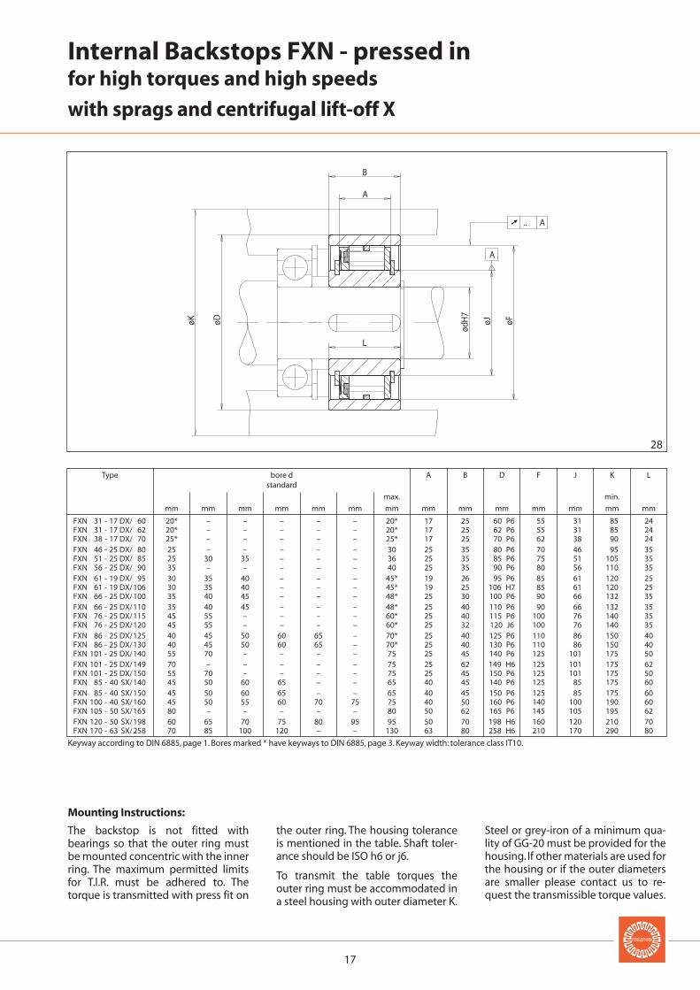
Internal Backstops FXN - pressed infor high torques and high speeds
with sprags and centrifugal lift-off X
Mounting Instructions:
The backstop is not fitted withbearings so that the outer ring mustbe mounted concentric with the innerring. The maximum permitted limitsfor T.l.R. must be adhered to. Thetorque is transmitted with press fit on
the outer ring. The housing toleranceis mentioned in the table. Shaft toler-ance should be ISO h6 or j6.
To transmit the table torques theouter ring must be accommodated ina steel housing with outer diameter K.
Steel or grey-iron of a minimum qua-lity of GG-20 must be provided for thehousing. If other materials are used forthe housing or if the outer diametersare smaller please contact us to re-quest the transmissible torque values.
Type bore d A B D F J K Lstandard
max. min.
mm mm mm mm mm mm mm mm mm mm mm mm mm mm
B
L
H7
ød
øJ øFøDøK
A
➚ 0,06 A
B
øJ-0
,01
-0,0
3
øFøDøK
A
➚ 0,06 A
37 SF 4869.037.123 37 SFT 4869.037.124 37 SF 4869.037.023 37 SFT 4869.037.024 220 1 050 20 25* - 25* 25 62 P6 55 37 85 3544 SF 4869.044.105 44 SFT 4869.044.107 44 SF 4869.044.005 44 SFT 4869.044.007 315 1 000 25 - - 32* 25 70 P6 62 44 90 3544 SF 4869.044.106 44 SFT 4869.044.108 44 SF 4869.044.005 44 SFT 4869.044.007 315 1 000 30 - - 32* 25 70 P6 62 44 90 19
57 SF 4869.057.105 57 SFT 4869.057.106 57 SF 4869.057.005 57 SFT 4869.057.006 630 900 30 35 40 42* 35 85 P6 75 57 105 4572 SF 4869.072.105 72 SFT 4869.072.107 72 SF 4869.072.005 72 SFT 4869.072.007 1 250 850 45 50 - 55* 36 100 P6 90 72 132 6082 SF 4869.082.104 82 SFT 4869.082.106 82 SF 4869.082.004 82 SFT 4869.082.006 1 900 800 50 55 - 65* 40 115 P6 100 82 140 60
82 SF 4869.082.105 82 SFT 4869.082.107 82 SF 4869.082.005 82 SFT 4869.082.007 1 900 800 50 55 - 65* 32 120 P6 100 82 140 60107 SF 4869.107.102 107 SFT 4869.107.104 107 SF 4869.107.002 107 SFT 4869.107.004 2 800 750 70 - - 85* 45 140 P6 125 107 175 65107 SF 4869.107.103 107 SFT 4869.107.105 107 SF 4869.107.003 107 SFT 4869.107.005 2 800 750 70 - - 85* 45 150 P6 125 107 175 65
127 SF 4869.127.109 127 SFT 4869.127.111 127 SF 4869.127.009 127 SFT 4869.127.011 4 000 500 90 - - 100* 62 165 P6 145 127 195 75
29 30
18
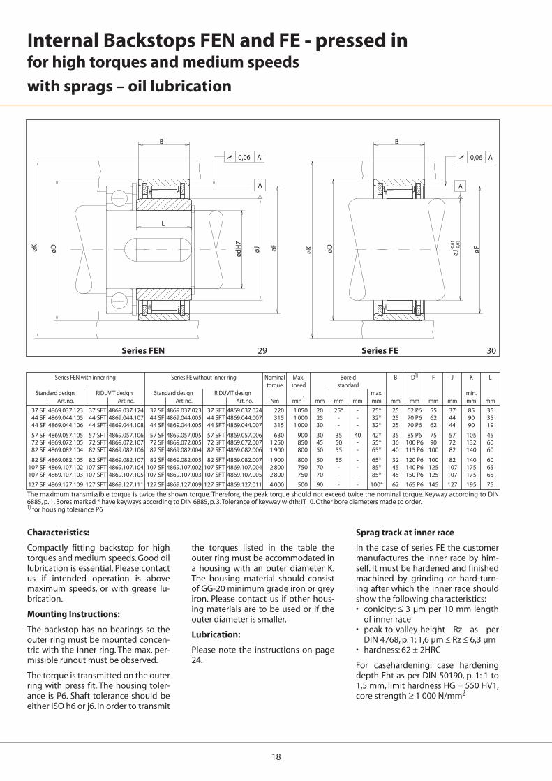
Internal Backstops FEN and FE - pressed infor high torques and medium speeds
with sprags – oil lubrication
Series FEN with inner ring Series FE without inner ring Nominal Max. Bore d B D1) F J K Ltorque speed standard
Standard design RIDUVIT design Standard design RIDUVIT design max. min.Art. no. Art. no. Art. no. Art. no. Nm min-1 mm mm mm mm mm mm mm mm mm mm
The maximum transmissible torque is twice the shown torque. Therefore, the peak torque should not exceed twice the nominal torque. Keyway according to DIN6885, p. 1. Bores marked * have keyways according to DIN 6885, p. 3.Tolerance of keyway width: IT10. Other bore diameters made to order.1) for housing tolerance P6
the torques listed in the table theouter ring must be accommodated ina housing with an outer diameter K.The housing material should consistof GG-20 minimum grade iron or greyiron. Please contact us if other hous-ing materials are to be used or if theouter diameter is smaller.
Lubrication:
Please note the instructions on page24.
Characteristics:
Compactly fitting backstop for hightorques and medium speeds. Good oillubrication is essential. Please contactus if intended operation is abovemaximum speeds, or with grease lu-brication.
Mounting Instructions:
The backstop has no bearings so theouter ring must be mounted concen-tric with the inner ring. The max. per-missible runout must be observed.
The torque is transmitted on the outerring with press fit. The housing toler-ance is P6. Shaft tolerance should beeither ISO h6 or j6. In order to transmit
Sprag track at inner race
In the case of series FE the customermanufactures the inner race by him-self. It must be hardened and finishedmachined by grinding or hard-turn-ing after which the inner race shouldshow the following characteristics:• conicity: ≤ 3 µm per 10 mm length
of inner race • peak-to-valley-height Rz as per
DIN 4768, p. 1: 1,6 µm ≤ Rz ≤ 6,3 µm• hardness: 62 ± 2HRC
For casehardening: case hardeningdepth Eht as per DIN 50190, p. 1: 1 to1,5 mm, limit hardness HG = 550 HV1,core strength ≥ 1 000 N/mm2
Series FEN Series FE
BA 20 DXG 6445.020.044 400 750 2 500 30 20 30 110 90 106 8 80 2.5 77 11 104 19.5 65 70 M10BA 25 DXG 6445.025.044 650 700 2 350 40 25 40 126 100 126 8 90 2.5 93 11 125 19.5 75 80 M12BA 30 DXG 6445.030.044 1 100 630 2 350 50 30 50 155 120 151 10 120 3.5 102 16 140 27.5 95 100 M16
BA 40 SXG 6445.040.044 1 400 430 2 200 60 40 60 190 150 181 12 160 5.5 116 22 160 37.5 130 120 M16BA 45 SXG 6445.045.044 2 300 400 2 200 65 45 70 210 160 196 14 175 7,5 130 26 176 41.5 140 130 M16BA 52 SXG 6445.052.044 4 900 320 2 200 80 50 80 230 190 216 14 200 4.5 150 26 208 41.5 160 150 M20
BA 55 SXG 6445.055.044 6 500 320 2 000 90 50 90 255 200 246 15 210 3.5 170 29 228 49.5 170 160 M20BA 60 SXG 6445.060.044 14 500 250 1 800 100 60 105 295 220 291 20 250 8.5 206 35 273 60,5 200 190 M24BA 70 SXG 6445.070.044 21 000 240 1 650 120 70 120 335 260 321 25 280 14,5 215 39 291 65,5 225 210 M24
BA 100 SXG 6445.100.044 42 500 210 1 450 150 100 150 420 380 411 45 345 31.5 276 60 372 80,5 280 270 M30
31 32
19
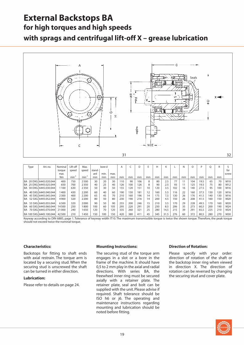
External Backstops BAfor high torques and high speeds
with sprags and centrifugal lift-off X – grease lubrication
Type Art. no. Nominal Lift-off Max. bore d A C D E H K L N O P Q R Storque speed speed stand- for
max. ard min. max. screwNm min-1 min-1 mm mm mm mm mm mm mm mm mm mm mm mm mm mm mm
Keyway according to DIN 6885, page 1. Tolerance of keyway width IT10. The maximum transmissible torque is twice the shown torque. Therefore, the peak torqueshould not exceed twice the nominal torque.
Mounting Instructions:
The securing stud of the torque armengages in a slot or a bore in theframe of the machine. It should have0,5 to 2 mm play in the axial and radialdirections. With series BA, thefreewheel inner ring must be securedaxially with a retainer plate. Theretainer plate, seal and bolt can besupplied with the unit. Please advise ifrequired. Shaft tolerance should beISO h6 or j6. The operating andmaintenance instructions regardingmounting and lubrication should benoted before fitting.
Characteristics:
Backstops for fitting to shaft endswith axial restrain. The torque arm islocated by a securing stud. When thesecuring stud is unscrewed the shaftcan be turned in either direction.
Lubrication:
Please refer to details on page 24.
Direction of Rotation:
Please specify with your order:direction of rotation of the shaft orthe backstop inner ring when viewedin direction X. The direction ofrotation can be reversed by changingthe securing stud and cover plate.
Seals
20
BA 20 DX 6440.020.044 BC 20 DX 6440.020.043 400 750 1 700 30 20 30 110 90 106 8 80 2.5 77 11 104 19.5 65 70 M10BA 25 DX 6440.025.044 BC 25 DX 6440.025.043 650 700 1 600 40 25 40 126 100 126 8 90 2.5 93 11 125 19.5 75 80 M12BA 30 DX 6440.030.044 BC 30 DX 6440.030.043 1 100 630 1 600 50 30 50 155 120 151 10 120 3.5 102 16 140 27.5 95 100 M16
BA 40 SX 6440.040.044 BC 40 SX 6440.040.043 1 400 430 1 500 60 40 60 190 150 181 12 160 5.5 116 22 160 37.5 130 120 M16BA 45 SX 6440.045.044 BC 45 SX 6440.045.043 2 300 400 1 500 65 45 70 210 160 196 14 175 7,5 130 26 176 41.5 140 130 M16BA 52 SX 6440.052.044 BC 52 SX 6440.052.043 4 900 320 1 500 80 50 80 230 190 216 14 200 4.5 150 26 208 41.5 160 150 M20
BA 55 SX 6440.055.044 BC 55 SX 6440.055.043 6 500 320 1 250 90 50 90 255 200 246 15 210 3.5 170 29 228 49.5 170 160 M20BA 60 SX 6440.060.044 BC 60 SX 6440.060.043 14 500 250 1 100 100 60 105 295 220 291 20 250 8.5 206 35 273 60,5 200 190 M24BA 70 SX 6440.070.044 BC 70 SX 6440.070.043 21 000 240 1 000 120 70 120 335 260 321 25 280 14,5 215 39 291 65,5 225 210 M24
BA 100 SX 6440.100.044 BC 100 SX 6440.100.043 42 500 210 750 150 100 150 420 380 411 45 345 31.5 276 60 372 80,5 280 270 M30
33 34 35
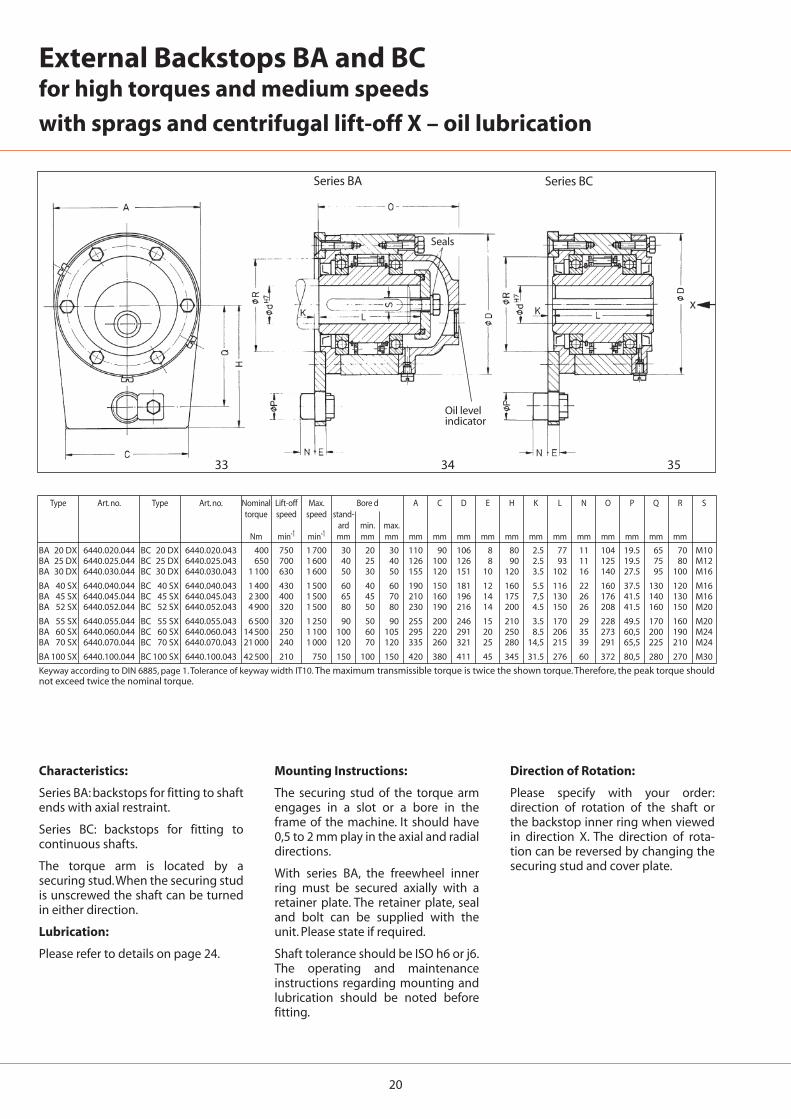
External Backstops BA and BCfor high torques and medium speeds
with sprags and centrifugal lift-off X – oil lubrication
Type Art. no. Type Art. no. Nominal Lift-off Max. Bore d A C D E H K L N O P Q R Storque speed speed stand-
ard min. max.Nm min-1 min-1 mm mm mm mm mm mm mm mm mm mm mm mm mm mm mm
Keyway according to DIN 6885, page 1. Tolerance of keyway width IT10. The maximum transmissible torque is twice the shown torque. Therefore, the peak torque shouldnot exceed twice the nominal torque.
Series BA Series BC
Oil levelindicator
Mounting Instructions:
The securing stud of the torque armengages in a slot or a bore in theframe of the machine. It should have0,5 to 2 mm play in the axial and radialdirections.
With series BA, the freewheel innerring must be secured axially with aretainer plate. The retainer plate, sealand bolt can be supplied with theunit. Please state if required.
Shaft tolerance should be ISO h6 or j6.The operating and maintenanceinstructions regarding mounting andlubrication should be noted beforefitting.
Characteristics:
Series BA: backstops for fitting to shaftends with axial restraint.
Series BC: backstops for fitting tocontinuous shafts.
The torque arm is located by asecuring stud.When the securing studis unscrewed the shaft can be turnedin either direction.
Lubrication:
Please refer to details on page 24.
Direction of Rotation:
Please specify with your order:direction of rotation of the shaft orthe backstop inner ring when viewedin direction X. The direction of rota-tion can be reversed by changing thesecuring stud and cover plate.
Seals
21
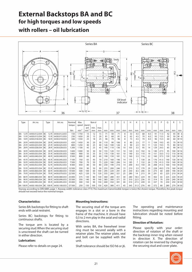
BA 12 R 6430.012.034 BC 12 R 6430.012.033 150 1 750 15 12 15 71 50 71 8 53 4.5 68 8.5 91 11.5 42 45 M 6BA 15 R 6430.015.034 BC 15 R 6430.015.033 230 1 650 20 15 20 81 60 81 8 62 4.5 70 8.5 93 13.5 50 50 M 6BA 18 R 6430.018.034 BC 18 R 6430.018.033 340 1 550 25 18 25 96 70 96 8 73 4.5 70 8.5 96 15.5 60 60 M 10
BA 20 R 6430.020.034 BC 20 R 6430.020.033 420 1 450 30 20 30 110 90 106 8 80 2.5 77 11 104 19.5 65 70 M 10BA 25 R 6430.025.034 BC 25 R 6430.025.033 800 1 250 40 25 40 126 100 126 8 90 2.5 93 11 125 19.5 75 80 M 12BA 28 R 6430.028.034 BC 28 R 6430.028.033 1 200 1 100 45 25 45 140 110 136 10 105 3.5 95 14 129 24.5 85 90 M 12
BA 30 R 6430.030.034 BC 30 R 6430.030.033 1 600 1 000 50 30 50 155 120 151 10 120 3.5 102 16 140 27.5 95 100 M 16BA 35 R 6430.035.034 BC 35 R 6430.035.033 1 800 900 55 35 55 170 130 161 10 140 3.5 110 19 151 33.5 112 110 M 16BA 40 R 6430.040.034 BC 40 R 6430.040.033 3 500 800 60 40 60 190 150 181 12 160 5.5 116 22 160 37.5 130 120 M 16
BA 45 R 6430.045.034 BC 45 R 6430.045.033 7 100 750 65 45 70 210 160 196 14 175 7 130 26 176 41.5 140 130 M 16BA 50 R 6430.050.034 BC 50 R 6430.050.033 7 500 700 70 50 75 220 180 206 14 185 7 132 26 178 41.5 150 140 M 16BA 52 R 6430.052.034 BC 52 R 6430.052.033 9 300 650 80 50 80 230 190 216 14 200 4.5 150 26 208 41.5 160 150 M 20
BA 55 R 6430.055.034 BC 55 R 6430.055.033 12 500 550 90 50 90 255 200 246 15 210 3.5 170 29 228 49.5 170 160 M 20BA 60 R 6430.060.034 BC 60 R 6430.060.033 14 500 500 100 60 100 295 220 291 20 250 8.5 206 35 273 60 200 190 M 24BA 70 R 6430.070.034 BC 70 R 6430.070.033 22 500 425 120 70 120 335 260 321 25 280 14 215 39 291 65 225 210 M 24
BA 80 R 6430.080.034 BC 80 R 6430.080.033 25 000 375 130 80 130 360 280 351 30 280 18.5 224 39 302 65 225 220 M 24BA 90 R 6430.090.034 BC 90 R 6430.090.033 33 500 350 140 90 140 385 300 371 35 310 22.5 236 55 314 70 250 240 M 30BA 95 R 6430.095.034 BC 95 R 6430.095.033 35 000 300 150 90 150 400 350 391 40 310 27.5 249 55 337 70 250 250 M 30
BA 100 R 6430.100.034 BC 100 R 6430.100.033 57 500 250 150 100 150 420 380 411 45 345 31.5 276 60 372 80 280 270 M 30
36 37 38
External Backstops BA and BCfor high torques and low speeds
with rollers – oil lubrication
Type Art. no. Type Art. no. Nominal Max. Bore d A C D E H K L N O P Q R Storque speed stand-
ard min. max.Nm min-1 min-1 mm mm mm mm mm mm mm mm mm mm mm mm mm mm mm
Keyway according to DIN 6885, page 1. Keyway width: tolerance class IT10.The maximum transmissible torque is twice the shown torque.Therefore, the peak torqueshould not exceed twice the nominal torque.
Mounting Instructions:
The securing stud of the torque armengages in a slot or a bore in theframe of the machine. It shouid have0,5 to 2 mm play in the axial and radialdirections.
With series BA, the freewheel innerring must be secured axially with aretainer plate. The retainer plate, sealand bolt can be supplied with theunit.
Shaft tolerance should be ISO h6 or j6.
Characteristics:
Series BA: backstops for fitting to shaftends with axial restraint.
Series BC: backstops for fitting tocontinuous shafts.
The torque arm is located by asecuring stud.When the securing studis unscrewed the shaft can be turnedin either direction.
Lubrication:
Please refer to details on page 24.
The operating and maintenanceinstructions regarding mounting andlubrication should be noted beforefitting.
Direction of Rotation:
Please specify with your order:direction of rotation of the shaft orthe backstop inner ring when viewedin direction X. The direction ofrotation can be reversed by changingthe securing stud and cover plate.
Series BA Series BC
Oil levelindicator
Seals
22
Baureihe FGR A2-A3 Baureihe FGR A3-A4
X
ød
H7
øD
EN
øP
Q
H
F
L
A3 A2
EN
øP
Q
H
F
O
ød
H7
øD
L
A3 A4
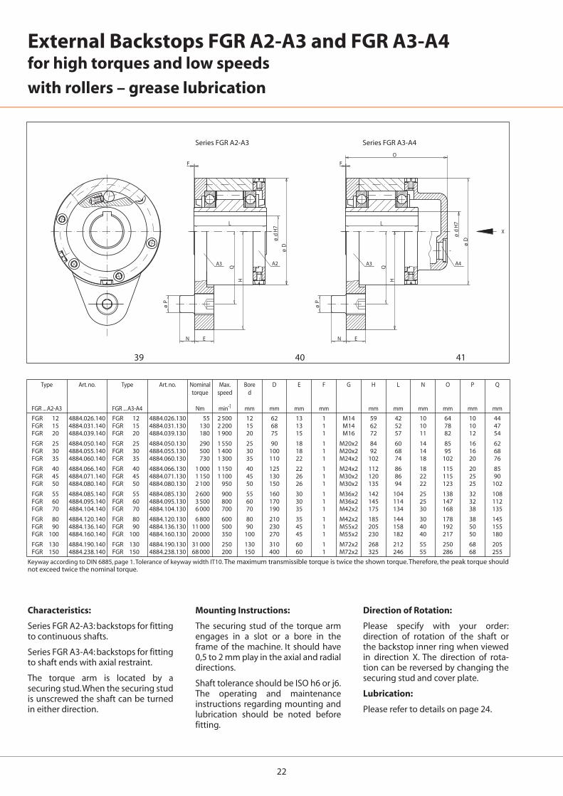
FGR 12 4884.026.140 FGR 12 4884.026.130 55 2 500 12 62 13 1 M14 59 42 10 64 10 44FGR 15 4884.031.140 FGR 15 4884.031.130 130 2 200 15 68 13 1 M14 62 52 10 78 10 47FGR 20 4884.039.140 FGR 20 4884.039.130 180 1 900 20 75 15 1 M16 72 57 11 82 12 54
FGR 25 4884.050.140 FGR 25 4884.050.130 290 1 550 25 90 18 1 M20x2 84 60 14 85 16 62FGR 30 4884.055.140 FGR 30 4884.055.130 500 1 400 30 100 18 1 M20x2 92 68 14 95 16 68FGR 35 4884.060.140 FGR 35 4884.060.130 730 1 300 35 110 22 1 M24x2 102 74 18 102 20 76
FGR 40 4884.066.140 FGR 40 4884.066.130 1 000 1 150 40 125 22 1 M24x2 112 86 18 115 20 85FGR 45 4884.071.140 FGR 45 4884.071.130 1 150 1 100 45 130 26 1 M30x2 120 86 22 115 25 90FGR 50 4884.080.140 FGR 50 4884.080.130 2 100 950 50 150 26 1 M30x2 135 94 22 123 25 102
FGR 55 4884.085.140 FGR 55 4884.085.130 2 600 900 55 160 30 1 M36x2 142 104 25 138 32 108FGR 60 4884.095.140 FGR 60 4884.095.130 3 500 800 60 170 30 1 M36x2 145 114 25 147 32 112FGR 70 4884.104.140 FGR 70 4884.104.130 6 000 700 70 190 35 1 M42x2 175 134 30 168 38 135
FGR 80 4884.120.140 FGR 80 4884.120.130 6 800 600 80 210 35 1 M42x2 185 144 30 178 38 145FGR 90 4884.136.140 FGR 90 4884.136.130 11 000 500 90 230 45 1 M55x2 205 158 40 192 50 155FGR 100 4884.160.140 FGR 100 4884.160.130 20 000 350 100 270 45 1 M55x2 230 182 40 217 50 180
FGR 130 4884.190.140 FGR 130 4884.190.130 31 000 250 130 310 60 1 M72x2 268 212 55 250 68 205FGR 150 4884.238.140 FGR 150 4884.238.130 68 000 200 150 400 60 1 M72x2 325 246 55 286 68 255
39 40 41
External Backstops FGR A2-A3 and FGR A3-A4for high torques and low speeds
with rollers – grease lubrication
Type Art. no. Type Art. no. Nominal Max. Bore D E F G H L N O P Qtorque speed d
FGR ... A2-A3 FGR ... A3-A4 Nm min-1 mm mm mm mm mm mm mm mm mm mm
Keyway according to DIN 6885, page 1. Tolerance of keyway width IT10. The maximum transmissible torque is twice the shown torque. Therefore, the peak torque shouldnot exceed twice the nominal torque.
Mounting Instructions:
The securing stud of the torque armengages in a slot or a bore in theframe of the machine. It should have0,5 to 2 mm play in the axial and radialdirections.
Shaft tolerance should be ISO h6 or j6.The operating and maintenanceinstructions regarding mounting andlubrication should be noted beforefitting.
Characteristics:
Series FGR A2-A3: backstops for fittingto continuous shafts.
Series FGR A3-A4: backstops for fittingto shaft ends with axial restraint.
The torque arm is located by asecuring stud.When the securing studis unscrewed the shaft can be turnedin either direction.
Direction of Rotation:
Please specify with your order:direction of rotation of the shaft orthe backstop inner ring when viewedin direction X. The direction of rota-tion can be reversed by changing thesecuring stud and cover plate.
Lubrication:
Please refer to details on page 24.
Series FGR A2-A3 Series FGR A3-A4
23
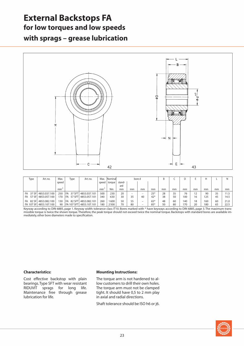
FA 37 SF 4853.037.100 250 FA 37 SFT 4853.037.101 500 230 20 – – 25* 28 35 76 12 90 35 11.5FA 57 SF 4853.057.100 170 FA 57 SFT 4853.057.101 340 630 30 35 40 42* 38 50 100 16 125 45 14.5
FA 82 SF 4853.082.100 130 FA 82 SFT 4853.082.101 260 1 600 50 55 – 65* 48 60 140 18 160 60 21,0FA 107 SF 4853.107.100 90 FA 107 SFT 4853.107.101 180 2 500 70 80 – 85* 50 80 170 20 180 65 22.5
42 43
External Backstops FAfor low torques and low speeds
with sprags – grease lubrication
Type Art. no. Max. Type Art. no. Max. Nominal bore d B C D E H L Nspeed speed torque stand-
ardmin-1 min-1 Nm mm mm mm mm mm mm mm mm mm mm mm
Keyway according to DIN 6885, page 1. Keyway width: tolerance class IT10. Bores marked with * have keyways according to DIN 6885, page 3. The maximum trans-missible torque is twice the shown torque. Therefore, the peak torque should not exceed twice the nominal torque. Backstops with standard bores are available im-mediately, other bore diameters made to specification.
Mounting Instructions:
The torque arm is not hardened to al-low customers to drill their own holes.The torque arm must not be clampedtight. It should have 0,5 to 2 mm playin axial and radial directions.
Shaft tolerance should be ISO h6 or j6.
Characteristics:
Cost effective backstop with plainbearings.Type SFT with wear resistantRIDUVIT sprags for long life.Maintenance free through greaselubrication for life.
24
Lubrication
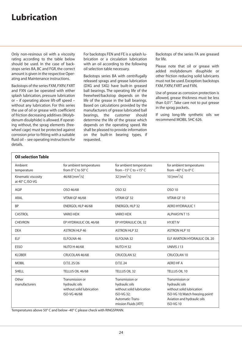
Only non-resinous oil with a viscosityrating according to the table belowshould be used. In the case of back-stops series BA, BC and FGR, the correctamount is given in the respective Oper-ating and Maintenance instructions.
Backstops of the series FXM, FXRV, FXRTand FXN can be operated with eithersplash lubrication, pressure lubricationor – if operating above lift-off speed –without any lubrication. For this seriesthe use of oil or grease with coefficientof friction decreasing additives (Molyb-denum disulphide) is allowed. If operat-ing without, the sprag elements (free-wheel cage) must be protected againstcorrosion prior to fitting with a suitablefluid oil – see operating instructions fordetails.
For backstops FEN and FE is a splash lu-brication or a circulation lubricationwith an oil according to the followingoil selection table necessary.
Backstops series BA with centrifugallyreleased sprags and grease lubrication(DXG and SXG) have built-in greasedball bearings. The operating life of thefreewheel/backstop depends on thelife of the grease in the ball bearings.Based on calculations provided by themanufacturers of grease lubricated ballbearings, the customer shoulddetermine the life of the grease whichdepends on the operating speed. Weshall be pleased to provide informationon the built-in bearing types, ifrequested.
Backstops of the series FA are greasedfor life.
Please note that oil or grease withadded molybdenum disuphide orother friction reducing solid lubricantsmust not be used. Exception: backstopsFXM, FXRV, FXRT and FXN.
Use of grease as corrosion protection isallowed, grease thickness must be lessthan 0,01“. Take care not to put greasein the sprag pockets.
If using long-life synthetic oils werecommend MOBIL SHC 626.
Temperatures above 50° C and below -40° C please check with RINGSPANN.
Oil selection Table
Ambient for ambient temperatures for ambient temperatures for ambient temperaturestemperature from 0° C to 50° C from –15° C to +15° C from –40° C to 0° C
Kinematic viscosity 46/68 [mm2/s] 32 [mm2/s] 10 [mm2/s]at 40° C, ISO-VG
AGIP OSO 46/68 OSO 32 OSO 10
ARAL VITAM GF 46/68 VITAM GF 32 VITAM GF 10
BP ENERGOL HLP 46/68 ENERGOL HLP 32 AERO HYDRAULIC 1
CASTROL VARIO HDX VARIO HDX ALPHASYN T 15
CHEVRON EP HYDRAULIC OIL 46/68 EP HYDRAULIC OIL 32 HYJET IV
DEA ASTRON HLP 46 ASTRON HLP 32 ASTRON HLP 10
ELF ELFOLNA 46 ELFOLNA 32 ELF AVIATION HYDRAULIC OIL 20
ESSO NUTO H 46/68 NUTO H 32 UNIVIS J 13
KLÜBER CRUCOLAN 46/68 CRUCOLAN 32 CRUCOLAN 10
MOBIL D.T.E. 25/26 D.T.E. 24 AERO HF A
SHELL TELLUS OIL 46/68 TELLUS OIL 32 TELLUS OIL 10
Other Transmission or Transmission or Transmission ormanufacturers hydraulic oils hydraulic oils hydraulic oils
without solid lubrication without solid lubrication without solid lubricationISO-VG 46/68 ISO-VG 32; ISO-VG 10;Watch freezing point!
Automatic-Trans- Aviation and hydraulic oilsmission Fluids [ATF] ISO-VG 10
25
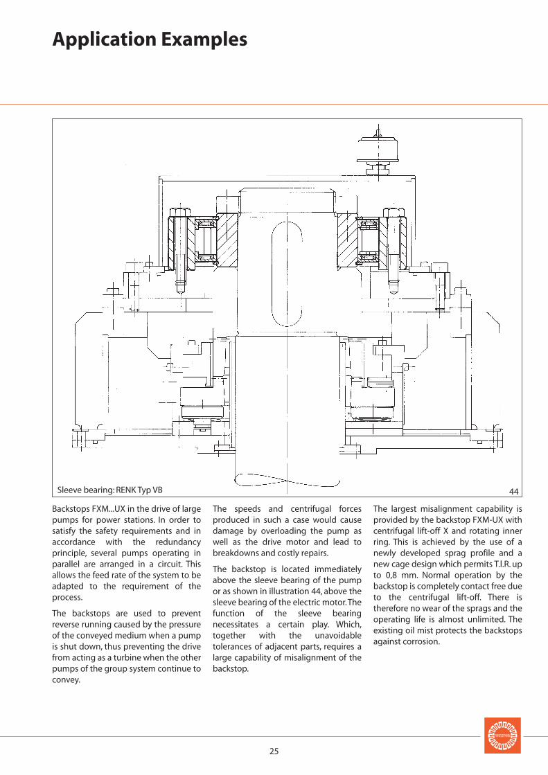
44Sleeve bearing: RENK Typ VB
Backstops FXM...UX in the drive of largepumps for power stations. In order tosatisfy the safety requirements and inaccordance with the redundancyprinciple, several pumps operating inparallel are arranged in a circuit. Thisallows the feed rate of the system to beadapted to the requirement of theprocess.
The backstops are used to preventreverse running caused by the pressureof the conveyed medium when a pumpis shut down, thus preventing the drivefrom acting as a turbine when the otherpumps of the group system continue toconvey.
The speeds and centrifugal forcesproduced in such a case would causedamage by overloading the pump aswell as the drive motor and lead tobreakdowns and costly repairs.
The backstop is located immediatelyabove the sleeve bearing of the pumpor as shown in illustration 44, above thesleeve bearing of the electric motor.Thefunction of the sleeve bearingnecessitates a certain play. Which,together with the unavoidabletolerances of adjacent parts, requires alarge capability of misalignment of thebackstop.
The largest misalignment capability isprovided by the backstop FXM-UX withcentrifugal lift-off X and rotating innerring. This is achieved by the use of anewly developed sprag profile and anew cage design which permits T.l.R. upto 0,8 mm. Normal operation by thebackstop is completely contact free dueto the centrifugal lift-off. There istherefore no wear of the sprags and theoperating life is almost unlimited. Theexisting oil mist protects the backstopsagainst corrosion.
Application Examples
26
45
46
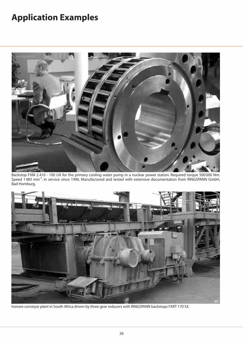
Backstop FXM 2.410 - 100 UX for the primary cooling water pump in a nuclear power station. Required torque 500 000 Nm.Speed 1 485 min-1. In service since 1996. Manufactured and tested with extensive documentation from RINGSPANN GmbH,Bad Homburg.
Ironore conveyor plant in South Africa driven by three gear reducers with RINGSPANN backstops FXRT 170 SX.
Application Examples
Schaberweg 30–34 61348 Bad Homburg
internet: http://www.ringspann.come-mail: [email protected]
Telefon +49 6172 275-0Telefax +49 6172 275-2 75
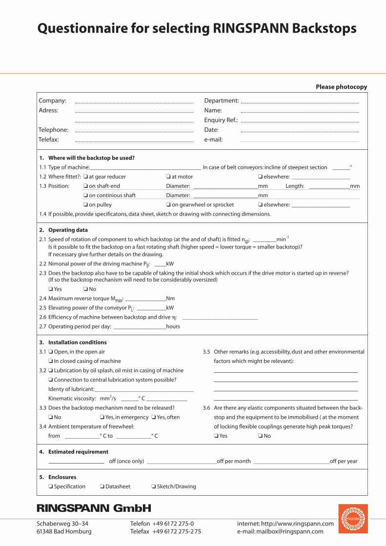
Questionnaire for selecting RINGSPANN Backstops
Company:
Adress:
Telephone:
Telefax:
Department:
Name:
Enquiry Ref.:
Date:
e-mail:
1. Where will the backstop be used?
1.1 Type of machine:______________________________________ In case of belt conveyors: incline of steepest section ______°
1.2 Where fittet?: ❏ at gear reducer ❏ at motor ❏ elsewhere: ____________________
1.3 Position: ❏ on shaft-end Diameter: ______________________mm Length: ______________mm
❏ on continious shaft Diameter: ______________________mm
❏ on pulley ❏ on gearwheel or sprocket ❏ elsewhere: ____________________
1.4 If possible, provide specificatons, data sheet, sketch or drawing with connecting dimensions.
2. Operating data
2.1 Speed of rotation of component to which backstop (at the and of shaft) is fitted nsp: ________min-1
Is it possible to fit the backstop on a fast rotating shaft (higher speed = lower torque = smaller backstop)?If necessary give further details on the drawing.
2.2 Nimonal power of the driving machine P0: ____kW
2.3 Does the backstop also have to be capable of taking the initial shock which occurs if the drive motor is started up in reverse?(If so the backstop mechanism will need to be considerably oversized)
❏ Yes ❏ No
2.4 Maximum reverse torque Mmax: ______________Nm
2.5 Elevating power of the conveyor PL: __________kW
2.6 Efficiency of machine between backstop and drive �: __________________________
2.7 Operating period per day: __________________hours
3. Installation conditions
3.1 ❏ Open, in the open air 3.5 Other remarks (e.g. accessibility, dust and other environmental
❏ In closed casing of machine factors which might be relevant):
3.2 ❏ Lubrication by oil splash, oil mist in casing of machine
❏ Connection to central lubrication system possible?
Identy of lubricant:__________________________________
Kinematic viscosity: mm2/s ______° C ______________
3.3 Does the backstop mechanism need to be released? 3.6 Are there any elastic components situated between the back-
❏ No ❏ Yes, in emergency ❏ Yes, often stop and the equipment to be immobilised ( at the moment
3.4 Ambient temperature of freewheel: of locking flexible couplings generate high peak torques?
from ____________° C to ____________° C ❏ Yes ❏ No
4. Estimated requirement
off (once only) ________________________off per month __________________________off per year
5. Enclosures
❏ Specification ❏ Datasheet ❏ Sketch/Drawing
Please photocopy
28
Freewheels
Brakes
Torque and Force Limiters
Couplings
Shaft-Hub-Connection
Precision Clamping Fixtures
Backstops
Automatic protectionagainst reverserunning of conveyor belts,elevators, pumps and fans.
Catalogue 88
Indexing Freewheels
For gradual feed of materials.
Catalogue 80
Overrunning Freewheels
Automatic engaging and disengaging of drives.
Catalogue 80
Freewheel Elements
Cage Freewheels,Sprag Sets andFreewheel Chains.
Catalogue 89
Industrial Disc Brakes
Manual Activated – Manual Release.
Catalogue 46
Industrial Disc Brakes
Spring Activated – Pneumatical, Hydraulical,Electromagnetical orManual Release.
Catalogue 46
Industrial Disc Brakes
Pneumatical Activated –Spring Release.
Catalogue 46
Industrial Disc Brakes
Hydraulical Activated –Spring Release.
Catalogue 46
Fail-Safe Clamping Units
For secure and precise positioning of piston rods.
Catalogue 32
Torque Limiter with Screw Face
Reliable overload protection for tough operating conditions.
Catalogue 45
Torque Limiter with Rollers
With double or single Roller. Through ratcheting or disengaging,also for 360°synchronous running.
Catalogue 45
Torque Limiter with Spherical Rollers
Reliable overload protection with maximum response accuracy. Also backlash free.
Catalogue 45
Torque Limiter with Friction Linings
RIMOSTAT Torque Limiter for con-stant torque.Belleville Spring Torque Limiter for simple release.
Catalogue 45
Force Limiter
Reliable axial overload protection in piston rods.
Catalogue 49
Flexible Couplings
Large, safe radial and angularmisaligne-ments.Minimum resiliency.
Catalogue 44
HELICAL-Flexures Spring Elements
Single Spring element with maximum resistance to wear.
Catalogue 43
Clamping Coupling
For the automatic coupling of rolls.Fast, safe and free from slipping connection.
Cone Clamping Elements
For shaft-hub connections.High torques with small dimensions.
Catalogue 31
Three-part Shrink Discs
External clamping connection for the fastening of hollow shafts on solid shafts
Catalogue 31
Star Discs
Ideal for shaft-hub-connection for frequentrelease.
Catalogue 30
Star Spring Washers
Axial spring elements for preloading of ball bearings.
Catalogue 20
Standard Parts forClamping Fixtures
The RINGSPANN-System for the manufacture of your own precision clamping fixtures.
Catalogue 14
Standard ClampingFixtures
Standard programme in high precision,ready manufac-tured chucks and mandrels.
Catalogue 13
Special ClampingFixtures
Custom made solutions for specific clamping problems.
Collet Mandrels
Universal, cost effective stan-dard series. Fast collet changeto other clamping diameters.
Catalogue 15
Hydraulic ExpandingClamping Tools
Mandrels and chucks withhigh concentricity.Clamping several workpieces in one process possible.
Catalogue 16
Two-part Shrink Discs
External clamping connection.Advantages:Simple, secure mounting even without torque wrench.
Catalogue 31.1
Housing Freewheels
Automatic engagingand disengaging formulti-motor drives for in-stallations with continu-ous operation.Catalogue 80.1
Flange couplings
Rigid, easily removable shaft coupling with no clearanceconeclamping elements.
HELICAL-Flexures Shaft Couplings
Design to meetrequirements for specific applica-tions. Connecting components can be integrated to save space.Catalogue 43
Schaberweg 30–34 61348 Bad Homburg
internet: http://www.ringspann.come-mail: [email protected]
Telefon +49 6172 275-0Telefax +49 6172 275-2 75
88e
20 K
emp
kes
09.0
4 · P
rin
ted
in G
erm
any