Embed Size (px)
Citation preview


Background◦ The design moment resistances of singly or doubly
reinforced sections with rectangular compressionzones can be easily determined using the General Design Chart in EBCS2:Part2. The Design Chart is prepared on the basis of parabolic-rectangular stress-strain (-) curves for concrete and elastic-plastic behavior with a horizontal or an inclined top branch for reinforcing bars.
◦ If the above conditions are not fulfilled, a trial-and-error solution based on strain compatibility can be used.

Steps for Determining the Design Axial Load and Uniaxial Bending Resistance◦ 1. Assume the strain distribution in the ULS◦ 2. for non-rectangular compression zone, the use
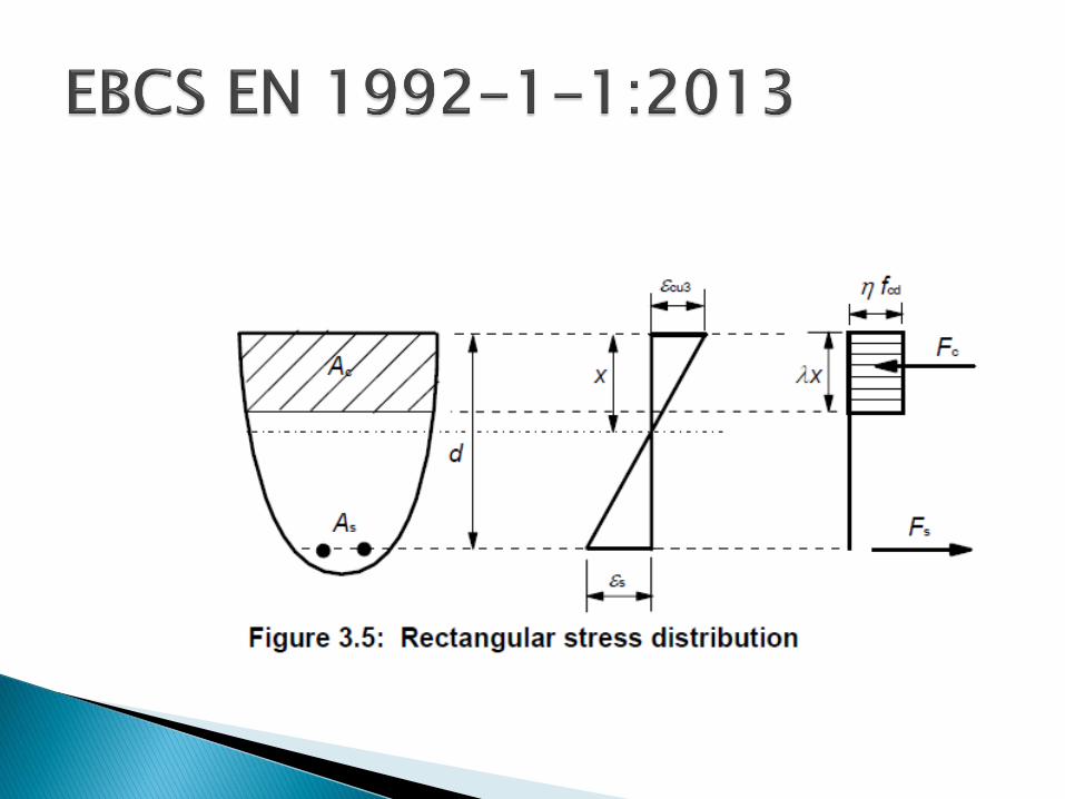
of the more accurate stress-strain curve of concrete tends to be involved. So use the equivalent rectangular stress block, with depth a = x (EBCS EN 1992-1-1: 2013 pp35 SNS)
◦ 3. compute the strains in each layer of reinforcement from the assumed strain distribution
◦ 4. from the stress-strain curve for the reinforcement and the strains from step 3, determine the stress in each layer of reinforcement

(3) A rectangular stress distribution (as given in Fig. 3.5) may be assumed. The factor ,
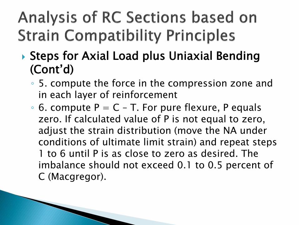
Steps for Axial Load plus Uniaxial Bending (Cont’d)◦ 5. compute the force in the compression zone and
in each layer of reinforcement
◦ 6. compute P = C – T. For pure flexure, P equals zero. If calculated value of P is not equal to zero, adjust the strain distribution (move the NA under conditions of ultimate limit strain) and repeat steps 1 to 6 until P is as close to zero as desired. The imbalance should not exceed 0.1 to 0.5 percent of C (Macgregor).
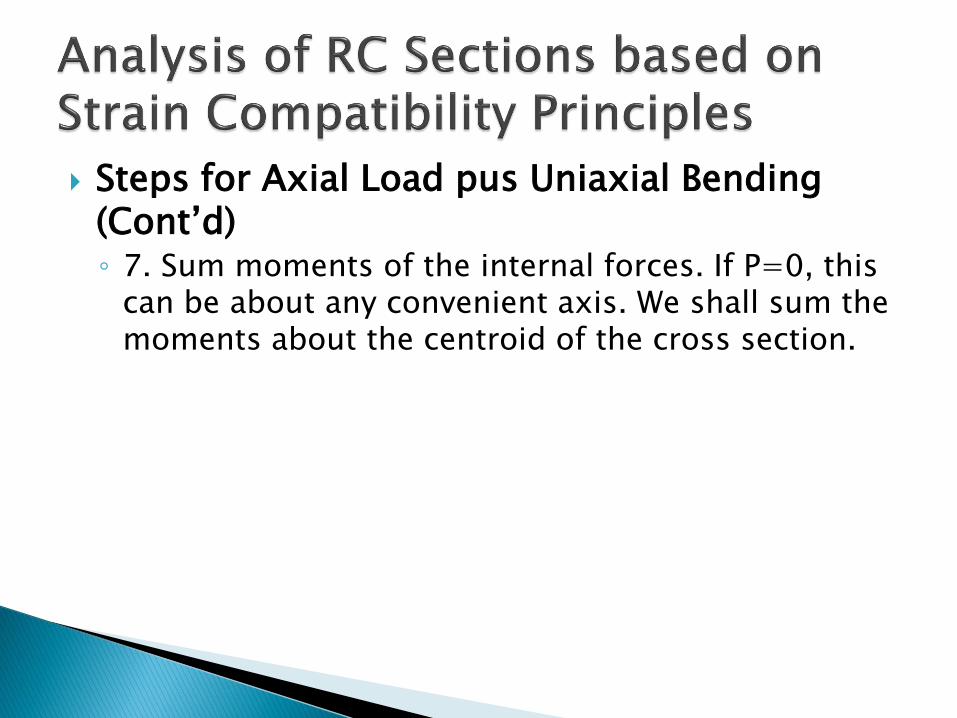
Steps for Axial Load pus Uniaxial Bending (Cont’d)◦ 7. Sum moments of the internal forces. If P=0, this
can be about any convenient axis. We shall sum the moments about the centroid of the cross section.

300 mm
Cover up to centroid of bars = 50 mm. C/C of bars on the longer side = 200 mmC20/25S400Rebar dia = 20 mm
y
z
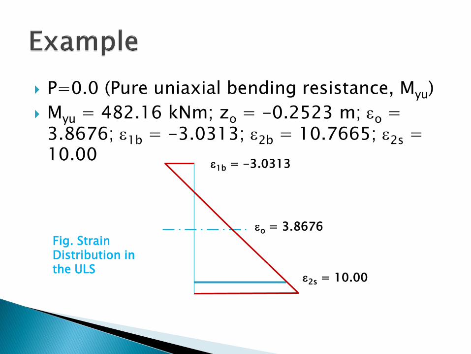
P=0.0 (Pure uniaxial bending resistance, Myu)
Myu = 482.16 kNm; zo = -0.2523 m; o = 3.8676; 1b = -3.0313; 2b = 10.7665; 2s = 10.00
Fig. Strain Distribution in the ULS
2s = 10.00
o = 3.8676
1b = -3.0313

Fig. Strain Distribution in the ULS
Cs
Cc
Ts2
Ts3
Ts4
Ts1
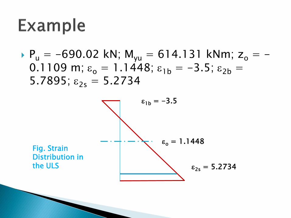
Pu = -690.02 kN; Myu = 614.131 kNm; zo = -0.1109 m; o = 1.1448; 1b = -3.5; 2b = 5.7895; 2s = 5.2734
2s = 5.2734
o = 1.1448Fig. Strain Distribution in the ULS
1b = -3.5

Pu = -1571.41kN; Myu = 559.359 kNm; Mzu
= 62.8592 kNm; y0 = -0.0674m; z0 = 0.0901m; o =-0.4257%o; 1b = -3.500%o; 2b
= 2.6487%o; 2s = 2.0964%o
NA, stress distribution, strain distribution in the ULS, etc. (See next slide)

z
y y0
z0
. . . .
. . . .

Applications (Cont’d)◦ Moment Resistance of Wall Assemblies, Walls with
Flanges, and Walls with Boundary Elements◦ Frequently, shear walls have webs and flanges that
act together to form H-, C-, T-, and L-shaped wall cross sections referred to as wall assemblies. The effective flange widths can be taken from ACI Code Sections 8.12.2 and 8.12.3 (or ES EN 1998-1-1). In regions subject to earthquakes, ACI Code Section 21.9.5.2 limits the flange widths to the smaller of (Refer to provisions by EN 1998-1) (a) half the distance to an adjacent web or
25 percent of the total height of wall


Applications (Cont’d)◦ Biaxially Loaded Walls: A wall is said to be biaxially
loaded if it resists axial load plus moments about two axes. One method of computing the strength of such walls is the equivalent eccentricity method. In this method a fraction b/n 0.4 and 0.8 times the weak-axis moment is added to the strong-axis moment. The wall is then designed for the axial load and the combined biaxial moment treated as a case of uniaxial bending and compression

Examples◦ 1. Reinforced Concrete T-wall Section
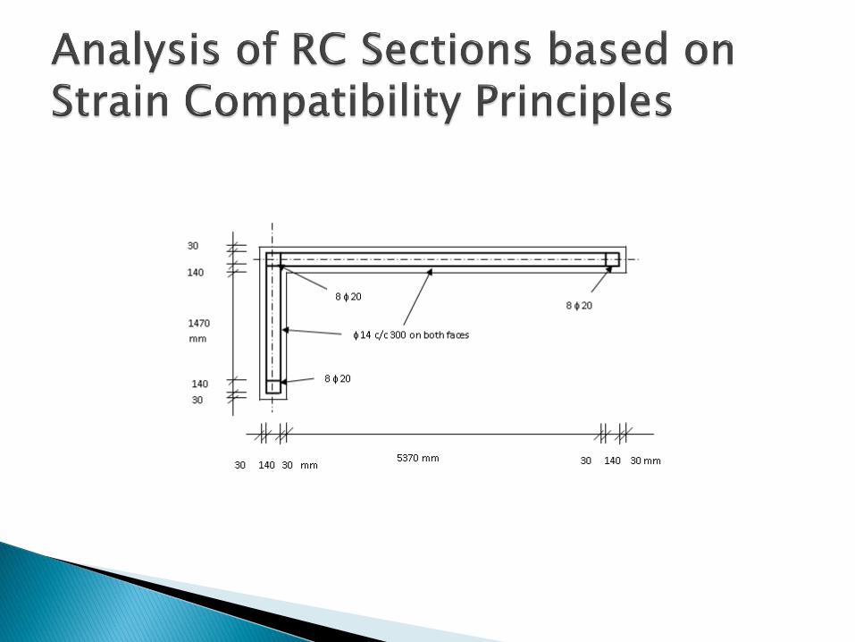
◦ The structural wall is reinforced with 14 c/c 300 along all faces and 8 20 as boundary elements, at the intersection and far ends of the flange and web (SNS). The steel grade and concrete class used are S-460 and C-30 respectively.
◦ Required is the design normal and biaxial bending resistance of the T-wall section

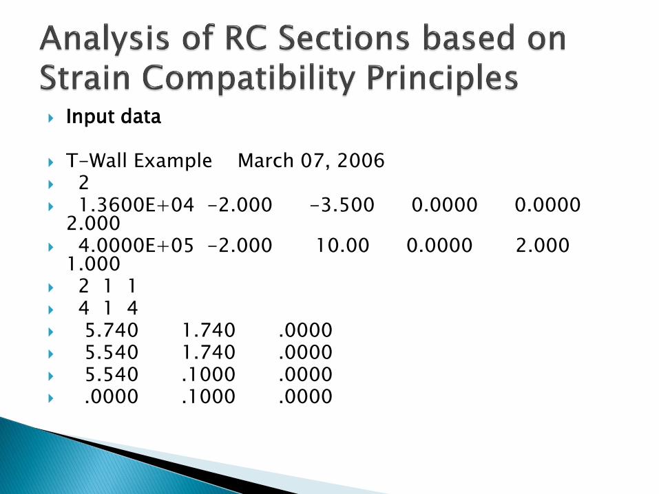
Input data
T-Wall Example March 07, 2006 2 1.3600E+04 -2.000 -3.500 0.0000 0.0000
2.000 4.0000E+05 -2.000 10.00 0.0000 2.000
1.000 2 1 1 4 1 4 5.740 1.740 .0000 5.540 1.740 .0000 5.540 .1000 .0000 .0000 .1000 .0000

43 2 4 .0300 .0000 3.14e-04 .0300 .0700 3.14e-04 .1000 .0700 3.14e-04 .1700 .0700 3.14e-04 .1700 .0000 3.14e-04 .4700 .0700 1.54e-04 .7700 .0700 1.54e-04 1.070 .0700 1.54e-04 1.370 .0700 1.54e-04 1.670 .0700 1.54e-04 1.970 .0700 1.54e-04 2.270 .0700 1.54e-04

2.570 .0700 1.54e-04 2.870 .0700 1.54e-04 3.170 .0700 1.54e-04 3.470 .0700 1.54e-04 3.770 .0700 1.54e-04 4.070 .0700 1.54e-04 4.370 .0700 1.54e-04 4.670 .0700 1.54e-04 4.970 .0700 1.54e-04 5.270 .0700 1.54e-04 5.570 .0700 3.14e-04 5.570 .0000 3.14e-04 5.640 .0700 3.14e-04 5.710 .0700 3.14e-04 5.710 .0000 3.14e-04 5.570 .3700 1.54e-04 5.570 .6700 1.54e-04

5.570 .9700 1.54e-04 5.570 1.270 1.54e-04 5.570 1.570 3.14e-04 5.640 1.570 3.14e-04 5.710 1.570 3.14e-04 5.570 1.640 3.14e-04 5.710 1.640 3.14e-04 5.570 1.710 3.14e-04 5.640 1.710 3.14e-04 5.710 1.710 3.14e-04 5.710 0.370 1.54e-04 5.710 0.670 1.54e-04 5.710 0.970 1.54e-04 5.710 1.270 1.54e-04 3 -2500. 7500.0 6500.0 0 0 0

------------------------------------- Factor of Safety to ULS ------------------------------------- N : -2500.00 M.y : 7500.00 M.z : 6500.00 N.u = -2592.93 M.yu = 7777.17 M.zu = 6740.05 R.u/R = 1.0370 alf.M = 40.9137 alf.k = 90.0844 alf.0 = 0.0844 y.0 _ = 117.662 z.0 = -0.1734 eps.0 = 0.3853 deps/dy = -0.0033 deps/dz = 2.2221 eps.1b = -3.5000 eps.2b = 4.2337 eps.2s = 4.1669 -------------------------------------------------------- Input Data: twall.dat Output Data: twall.out
Internal forces w.r.t centroid of concrete section: ySP = 3.8773 zSP = 0.0000

z
y
2. Reinforced Concrete L-wall Section
The reinforcement, material strength and design action effects are similar to the T-wall example in section 4.2. The factor of safety of 0.32 indicates that the design has to be revised.

A.6 Input Data
L-Wall Example March 07, 2006 2 1.3600E+04 -2.000 -3.500 0.0000 0.0000
2.000 4.0000E+05 -2.000 10.00 0.0000 2.000 1.000 2 1 1 6 1 1 5.740 1.740 .0000 5.540 1.740 .0000 5.540 .1000 .0000 .0000 .1000 .0000 .0000 -.1000 .0000 5.740 -.1000 .0000

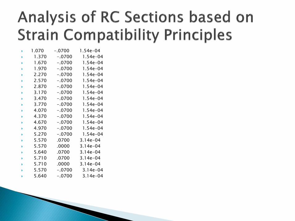
66 2 1 .0300 .0000 3.14e-04 .0300 .0700 3.14e-04 .1000 .0700 3.14e-04 .1700 .0700 3.14e-04 .1700 .0000 3.14e-04 .0300 -.0700 3.14e-04 .1000 -.0700 3.14e-04 .1700 -.0700 3.14e-04 .4700 .0700 1.54e-04 .7700 .0700 1.54e-04 1.070 .0700 1.54e-04 1.370 .0700 1.54e-04 1.670 .0700 1.54e-04 1.970 .0700 1.54e-04 2.270 .0700 1.54e-04 2.570 .0700 1.54e-04

2.870 .0700 1.54e-04
3.170 .0700 1.54e-04
3.470 .0700 1.54e-04
3.770 .0700 1.54e-04
4.070 .0700 1.54e-04
4.370 .0700 1.54e-04
4.670 .0700 1.54e-04
4.970 .0700 1.54e-04
5.270 .0700 1.54e-04
.4700 -.0700 1.54e-04
.7700 -.0700 1.54e-04
1.070 -.0700 1.54e-04
1.370 -.0700 1.54e-04
1.670 -.0700 1.54e-04
1.970 -.0700 1.54e-04
2.270 -.0700 1.54e-04
2.570 -.0700 1.54e-04
2.870 -.0700 1.54e-04
3.170 -.0700 1.54e-04
3.470 -.0700 1.54e-04
3.770 -.0700 1.54e-04
4.070 -.0700 1.54e-04
4.370 -.0700 1.54e-04
4.670 -.0700 1.54e-04
4.970 -.0700 1.54e-04
5.270 -.0700 1.54e-04
5.570 .0700 3.14e-04
5.570 .0000 3.14e-04
5.640 .0700 3.14e-04
5.710 .0700 3.14e-04
5.710 .0000 3.14e-04
5.570 -.0700 3.14e-04
5.640 -.0700 3.14e-04

5.710 -.0700 3.14e-04
5.570 .3700 1.54e-04
5.570 .6700 1.54e-04
5.570 .9700 1.54e-04
5.570 1.270 1.54e-04
5.570 1.570 3.14e-04
5.640 1.570 3.14e-04
5.710 1.570 3.14e-04
5.570 1.640 3.14e-04
5.710 1.640 3.14e-04
5.570 1.710 3.14e-04
5.640 1.710 3.14e-04
5.710 1.710 3.14e-04
5.710 0.370 1.54e-04
5.710 0.670 1.54e-04
5.710 0.970 1.54e-04
5.710 1.270 1.54e-04
3
-2500. 7500.0 6500.0 0 0
0
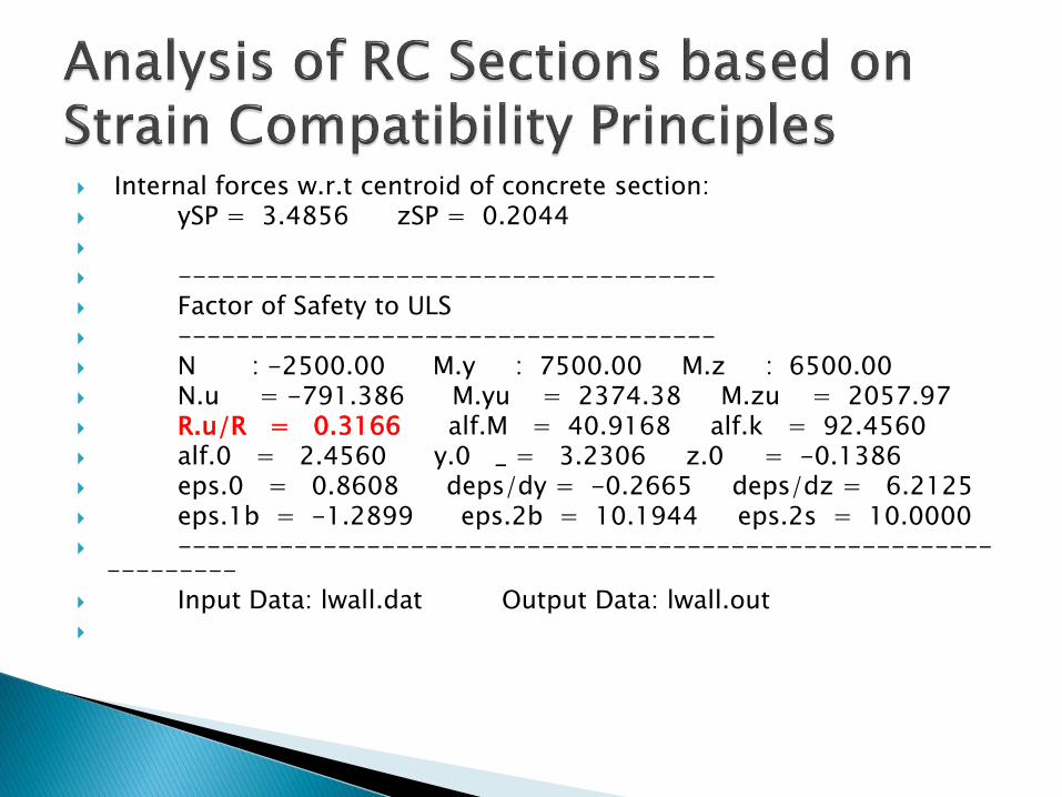
Internal forces w.r.t centroid of concrete section: ySP = 3.4856 zSP = 0.2044
------------------------------------- Factor of Safety to ULS ------------------------------------- N : -2500.00 M.y : 7500.00 M.z : 6500.00 N.u = -791.386 M.yu = 2374.38 M.zu = 2057.97 R.u/R = 0.3166 alf.M = 40.9168 alf.k = 92.4560 alf.0 = 2.4560 y.0 _ = 3.2306 z.0 = -0.1386 eps.0 = 0.8608 deps/dy = -0.2665 deps/dz = 6.2125 eps.1b = -1.2899 eps.2b = 10.1944 eps.2s = 10.0000 --------------------------------------------------------
--------- Input Data: lwall.dat Output Data: lwall.out

3. Column sections under biaxial bending (preparation of interaction diagrams)


A.4.1 Input Data
Biaxial- Rectangular X-Section with 8-rebars 26.02.06 2 1.3600E+04 -2.000 -3.500 0.0000 0.0000 2.000 4.0000E+05 -2.000 10.00 0.0000 2.000 1.000 2 3 1 1 1 5 0.2000 0.2000 0.0000 3 2 5 0.1200 0.1200 3.4000E-04 0.1200 0.0000 3.4000E-04 0.0000 0.1200 3.4000E-04 3 -1740.8 139.26 52.22 0 0 0
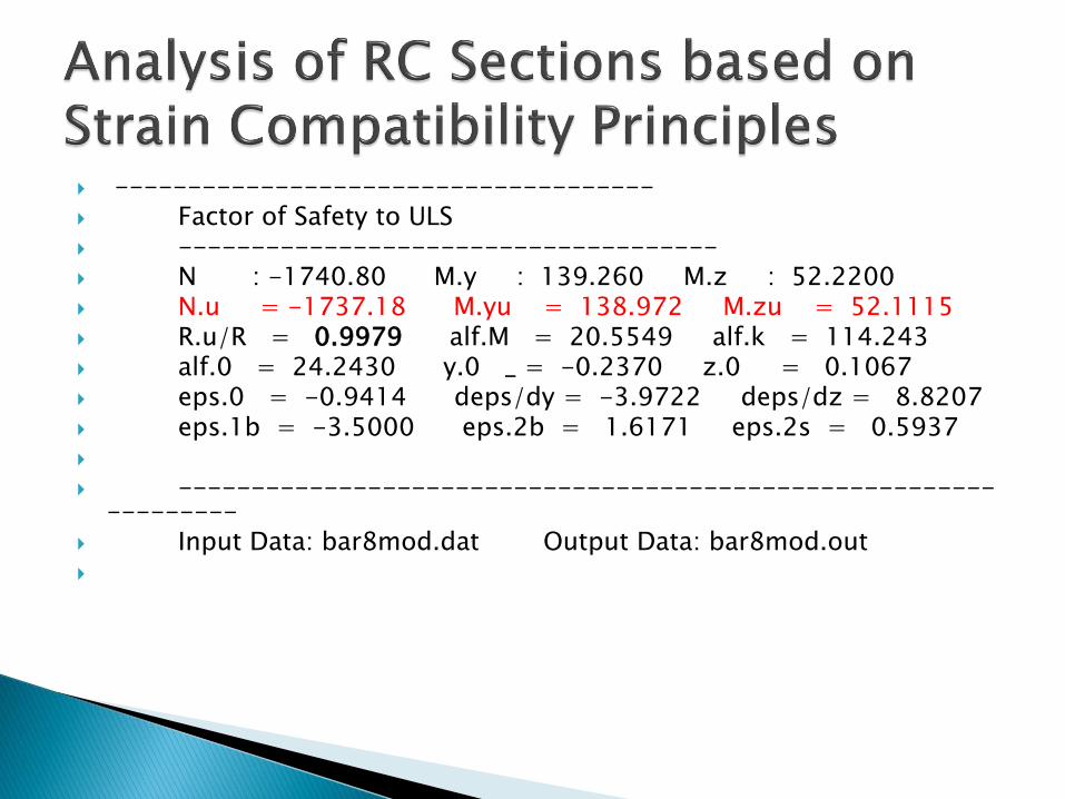
------------------------------------- Factor of Safety to ULS ------------------------------------- N : -1740.80 M.y : 139.260 M.z : 52.2200 N.u = -1737.18 M.yu = 138.972 M.zu = 52.1115 R.u/R = 0.9979 alf.M = 20.5549 alf.k = 114.243 alf.0 = 24.2430 y.0 _ = -0.2370 z.0 = 0.1067 eps.0 = -0.9414 deps/dy = -3.9722 deps/dz = 8.8207 eps.1b = -3.5000 eps.2b = 1.6171 eps.2s = 0.5937
-----------------------------------------------------------------
Input Data: bar8mod.dat Output Data: bar8mod.out

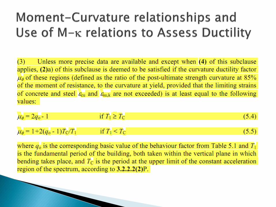
Ductility is an important property of RC structures. Why?
Concrete is a brittle material. However RC can display significant ductility if properly designed (normal RC structures and those designed for EQ resistance( displacement ductility and curvature ductility demands in EQ design))
Definition of ductility. How do we measure it? (displacement and/ or curvature ductility ratio )
See extract in next slide


The ductility provisions to ensure local and global ductility in the design of structures for earthquake resistance are in addition to the provisions in EBCS EN 1992-1-1 for ductile design of flexural members.
Discuss the provisions in terms of limitation of the NA depth and the role of compression reinforcements to improve ductility
Use the worksheet for calculation of moment-curvature
Define ductility with the help of the moment-curvature diagrams
Ductility decreases with increase in longitudinal tension reinforcement.
Ductility is enhanced with compression reinforcement. Discuss with the help of the example in Chapter 5.

Sudden w/o warning

Discuss ULS in shear (diagonal tension and diagonal compression)
ULS in shear is brittle and should be avoided. We will see how in Chapter 5

ULS in bond is also brittle and should be avoided. How?
By providing sufficient anchorage length, hooks, anchorage plates, etc.
Definition of ductility. Let us answer the question of how do we measure it? (displacement and/ or curvature ductility ratio)
Discuss moment-curvature using the worksheet example (Continue with structure failures for COTM)

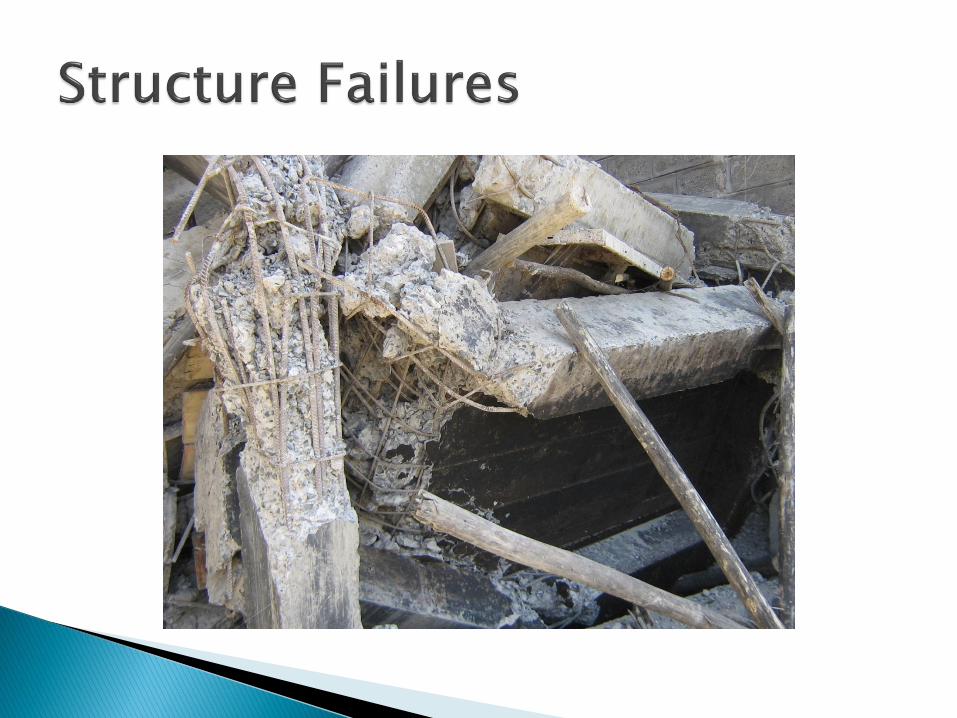
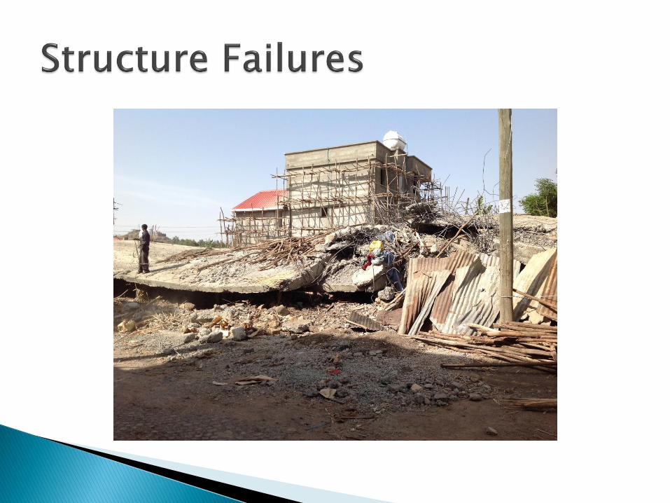
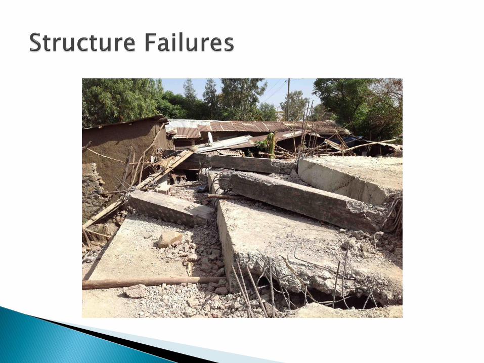
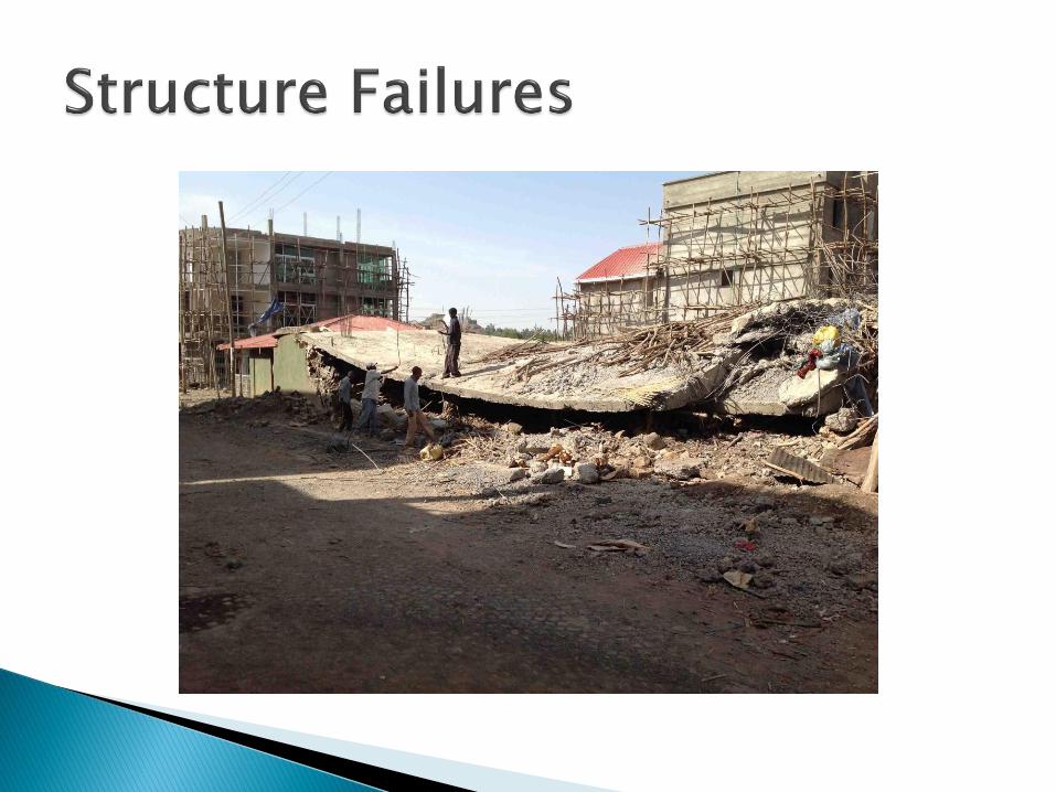
Structure as a whole may collapse w/o warning as a result of individual member failures
Example is Omo steel bridge failure
Structure could also collapse w/o warning as a result of a particular story or more than one story becoming unstable.
Examples are collapse of Gondar building and staircase in Addis.


Project staircase. It has collapsed suddenly w/o warning. Give dimensions and material strengths (C20/25 and S300 reinforcement)
Is it a stability failure? assignment: Using simple hand calculations determine the probable cause of collapse of the staircase in Addis. Make simplifying assumptions.
Such types of premature failures should be avoided