Embed Size (px)
Citation preview

2
Background
A recent pressure safety walk-down through LANSCE Area B resulted in a request to
perform a detailed analysis of certain size conflat flange pairs subject to internal
pressures. Though these systems in Area B have performed safely and well for a number
of years (with former pressure safety committee approval), it was deemed prudent that an
analysis be performed to insure a realistic factor of safety is present in the design as
implemented.
Analysis Details
The specific conflat flange sizes to be analyzed are 2.75 inch (with 1.5 inch OD, .065
inch wall tubing), 3.375 inch (with 1.5 inch OD, .065 inch wall tubing) and 4.625 inch
(with 3.0 inch OD, .065 inch wall tubing). All models are performed using room
temperature material data with 285 psi internal pressure (where the system relieves
internal pressure). In all cases, one flange in the pair is non-rotatable, and the other is
rotatable.
In all cases, bolts are included in the analysis and pre-loaded in tension, calculated by
using eq. 10.12 of Juvinall and Marshek [1] with torque specification given by MDC
(vendor) for the size in question (www.mdcvacuum.com).
T = 0.2Fid
This is an approximate relationship based on average thread friction conditions.
Mechanical Analyses
General Analysis Assumptions
The assembly was modeled with appropriate boundary conditions applied to simulate
a bolted flange pair subject to internal pressure. The software used to perform the
analyses was ANSYS Workbench v12.0. Geometry was ported to ANSYS via an .x_t
3
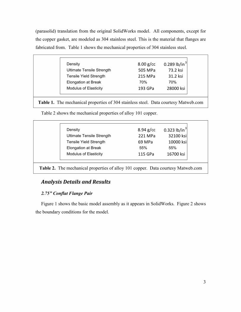
(parasolid) translation from the original SolidWorks model. All components, except for
the copper gasket, are modeled as 304 stainless steel. This is the material that flanges are
fabricated from. Table 1 shows the mechanical properties of 304 stainless steel.
Table 2 shows the mechanical properties of alloy 101 copper.
Analysis Details and Results
2.75” Conflat Flange Pair
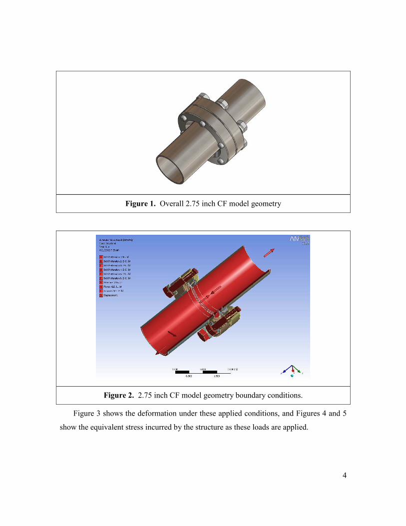
Figure 1 shows the basic model assembly as it appears in SolidWorks. Figure 2 shows
the boundary conditions for the model.
Table 1. The mechanical properties of 304 stainless steel. Data courtesy Matweb.com
Table 2. The mechanical properties of alloy 101 copper. Data courtesy Matweb.com
Density 8.94 g/cc 0.323 lb/in 3
Ultimate Tensile Strength 221 MPa 32100 ksi Tensile Yield Strength 69 MPa 10000 ksi Elongation at Break 55% 55% Modulus of Elasticity 115 GPa 16700 ksi
Density 8.00 g/cc 0.289 lb/in 3
Ultimate Tensile Strength 505 MPa 73.2 ksi Tensile Yield Strength 215 MPa 31.2 ksi Elongation at Break 70% 70% Modulus of Elasticity 193 GPa 28000 ksi
4
Figure 2. 2.75 inch CF model geometry boundary conditions.
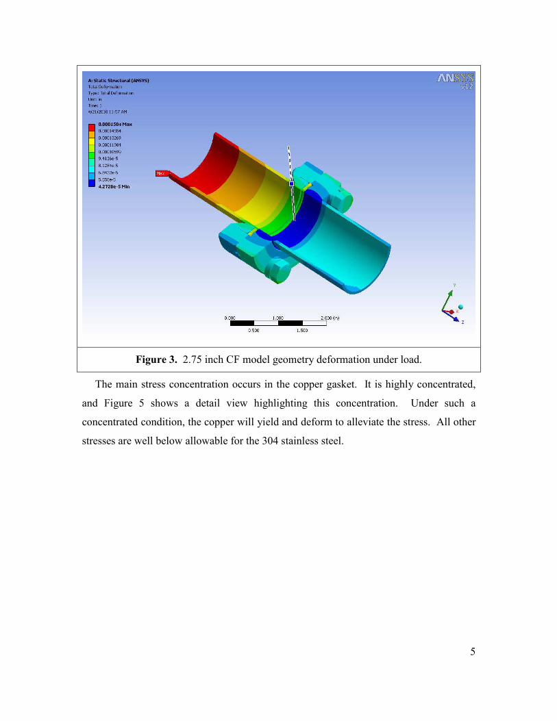
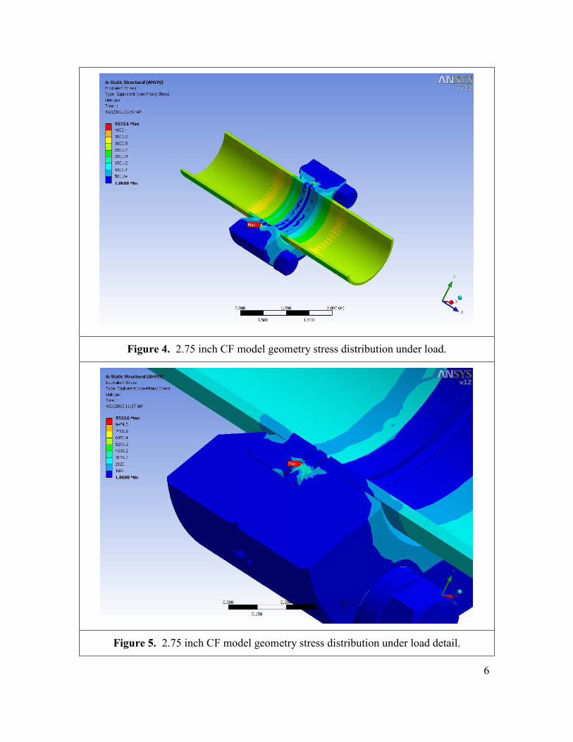
Figure 3 shows the deformation under these applied conditions, and Figures 4 and 5
show the equivalent stress incurred by the structure as these loads are applied.
Figure 1. Overall 2.75 inch CF model geometry
5
Figure 3. 2.75 inch CF model geometry deformation under load.
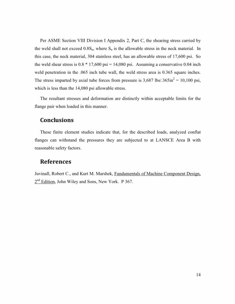
The main stress concentration occurs in the copper gasket. It is highly concentrated,
and Figure 5 shows a detail view highlighting this concentration. Under such a
concentrated condition, the copper will yield and deform to alleviate the stress. All other
stresses are well below allowable for the 304 stainless steel.
6
Figure 4. 2.75 inch CF model geometry stress distribution under load.
Figure 5. 2.75 inch CF model geometry stress distribution under load detail.

7
Per ASME Section VIII Division I Appendix 2, Part C, the shearing stress carried by
the weld shall not exceed 0.8Sn, where Sn is the allowable stress in the neck material. In
this case, the neck material, 304 stainless steel, has an allowable stress of 17,600 psi. So
the weld shear stress is 0.8 * 17,600 psi = 14,080 psi. Assuming a conservative 0.04 inch
weld penetration in the 0.065 inch tube wall, the weld stress area is 0.18 square inches.
The stress imparted by axial tube forces from pressure is 420.11 lbs/.18in2 = 2,332 psi, a
factor of 6 less than the 14,080 psi allowable stress.
The resultant stresses and deformations are well within acceptable limits for the flange
pair when loaded in this manner.
3.375” Conflat Flange Pair
Figure 6 shows the basic model assembly as it appears in SolidWorks. Figure 7 shows
the boundary conditions for the model.
Figure 6. Overall 3.375 inch CF model geometry

8
Figure 7. 3.375 inch CF model geometry boundary conditions.
Figure 8 shows the deformation under these applied conditions, and Figures 9 and 10
show the equivalent stress incurred by the structure as these loads are applied.
Figure 8. 3.375 inch CF model geometry deformation under load.
The main stress concentration occurs in the copper gasket. It is highly concentrated,
and Figure 10 shows a detail view highlighting this concentration. Under such a
concentrated condition, the copper will yield and deform to alleviate the stress. All other
stresses are well below allowable for the 304 stainless steel.

9
Figure 9. 3.375 inch CF model geometry stress distribution under load.
Figure 10. 3.375 inch CF model geometry stress distribution under load detail.
Per ASME Section VIII Division I Appendix 2, Part C, the shearing stress carried by
the weld shall not exceed 0.8Sn, where Sn is the allowable stress in the neck material. In
this case, the neck material, 304 stainless steel, has an allowable stress of 17,600 psi. So
the weld shear stress is 0.8 * 17,600 psi = 14,080 psi. Assuming a conservative 0.04 inch
weld penetration in the 0.065 inch tube wall, the weld stress area is 0.18 square inches.

10
The stress imparted by axial tube forces from pressure is 420.11 lbs/.18in2 = 2,332 psi, a
factor of 6 less than the 14,080 psi allowable stress.
The resultant stresses and deformations are well within acceptable limits for the flange
pair when loaded in this manner.
4.625” Conflat Flange Pair
Figure 11 shows the basic model assembly as it appears in SolidWorks. Figure 12
shows the boundary conditions for the model.
Figure 11. Overall 4.625 inch CF model geometry

11
Figure 12. 4.625 inch CF model geometry boundary conditions.
Figure 13 shows the deformation under these applied conditions, and Figures 14 and
15 show the equivalent stress incurred by the structure as these loads are applied.

12
Figure 13. 4.625 inch CF model geometry deformation under load.
The main stress concentration occurs in the copper gasket. It is highly concentrated,
and Figure 15 shows a detail view highlighting this concentration. Under such a
concentrated condition, the copper will yield and deform to alleviate the stress. All other
stresses are well below allowable for the 304 stainless steel.

13
Figure 14. 4.625 inch CF model geometry stress distribution under load.
Figure 15. 4.625 inch CF model geometry stress distribution under load detail.
14
Per ASME Section VIII Division I Appendix 2, Part C, the shearing stress carried by
the weld shall not exceed 0.8Sn, where Sn is the allowable stress in the neck material. In
this case, the neck material, 304 stainless steel, has an allowable stress of 17,600 psi. So
the weld shear stress is 0.8 * 17,600 psi = 14,080 psi. Assuming a conservative 0.04 inch
weld penetration in the .065 inch tube wall, the weld stress area is 0.365 square inches.
The stress imparted by axial tube forces from pressure is 3,687 lbs/.365in2 = 10,100 psi,
which is less than the 14,080 psi allowable stress.
The resultant stresses and deformation are distinctly within acceptable limits for the
flange pair when loaded in this manner.
Conclusions
These finite element studies indicate that, for the described loads, analyzed conflat
flanges can withstand the pressures they are subjected to at LANSCE Area B with
reasonable safety factors.
References
Juvinall, Robert C., and Kurt M. Marshek, Fundamentals of Machine Component Design,
2nd Edition
, John Wiley and Sons, New York. P 367.


![1. [Group] Slide01 2. background - Friendship Church · 1. [Group] Slide01 2. background 3. background 4. background!!"!!";&$ 5. Minnesota Miracle Reactio… 6. background!Make a](https://img.dokumen.tips/doc/110x75/5f29a750c10e4376fe0a71c0/1-group-slide01-2-background-friendship-church-1-group-slide01-2-background.jpg)