Embed Size (px)
Citation preview
Operating instructions
Dynamic 745
Engl
ish
with Generator ACU

Copyright by RINCO ULTRASONICS AG, Switzerland
Version 2 – ACU 2a06 – gb, Art.-No. 34039
Software versions:
Controller ACU 3C01, Press Dynamic 5P07, Generator DGC 0G27
2

3
Note
Before the machine is unpacked and started up,
these operating instructions must be read and their
content must be observed when operating the
machine.
The machine may only be operated, serviced and
repaired by persons who are familiar with these
operating instructions and the current statutory
regulations for health and safety at work.
Agency

Content
1 Safety 6
1.1 Explanation of symbols and signs 6
2 Safety advice 7
2.1 General 72.2 Agreed usage 72.3 Not used as intended 72.4 Special points to note 72.5 Choosing staff 72.6 Installation 72.7 Operation 82.8 Noise emissions 82.9 Emergency stop button 92.10 Guarantee explanation 9
3 Transport 10
3.1 Locating the equipment 103.2 Unpacking/Goods received inspection 103.3 Damage in transit 10
4 Product information 12
4.1 Product overview 124.1.1 Unit 124.1.2 Press 124.1.3 Oscillator system 134.1.4 Booster 134.1.5 Converter 144.1.6 Generator/Controller 14
5 Initial set-up 15
5.1 Assemble and connect the device 15
6 Operating and display elements 16
6.1 Multi-press 166.2 ACU Controller module 186.3 The graphics and text display 186.4 The Keyboard 20
7 Programming the equipment 22
7.1 Set-up 227.2 Setting the clamping table up 277.3 The weld cycle process 27
8 Weld technology 28
8.1 Process description 298.2 Dynamic 745 weld technology 30
9 Operating modes 32
9.1 Operating mode selection 329.2 The limits 329.3 The individual modes 33
10 Database/Data transfer 40
10.1 The Database 4010.2 Extended data evaluation 40
11 Init mode 42
11.1 System initialisation 4211.2 System initialisation “Init mode” 4211.3 Description of data string 47
11.3.1 Brief description 4711.3.2 Structure of the data string 4711.3.3 Example of an output 47
12 General maintenance work 48
12.1 Cleaning the equipment 4812.2 Clamping table 4812.3 Pneumatics unit 4812.4 Lubrication system 4812.5 Generator 4812.6 Oscillation system 4912.7 Screwed connections 4912.8 Error messages and their correction 50
during power on12.9 Error messages and their correction 5012.10 Error messages and their correction 50
during set-up and welding12.11 Interface pin assignment 5112.12 Generator fuses 5212.13 List of the generator fuses 52
13 Service Adresses 53
4

5
Important!
When contacting us with any questions relating toyour welding press Dynamic 745 and thegenerator, please be ready to give us the model des-cription and the unit serial number.This information is to be found on the rating plate (Aand B) on the side of the unit as well as on the backof the generator.
Dynamic 745:
Press with 745 N max. power
The design and switching of this device are constantly undergoing development and improvement and represent the present state of theart in terms of the technology used.
RINCO ULTRASONICS AGRomanshorn, Schweiz
Preface
We are very pleased that you chose to buy a RINCOproduct. We are convinced that you will achieve amaximum degree of economy of operation and pro-duct quality when using this unit.The purpose of this manual is to give the purchaserand the user all the information they need in termsof the handling, assembly, operation and care of thewelding press.To ensure that your system is always in an operational state, you should take note of andfollow all the tips and instructions containedwithin this manual.
B

1 Safety
1.1 Explanation of symbols and signs
Hazard warnings and notices of caution are highlighted by symbols. The symbols are displayed inthe operating instructions and some even onthe welding equipment itself. All hazard warnings andcaution symbols describe circumstances in whichpeople could be harmed, objects and the environ-ment could suffer damage if disregarded.
Hazard warning symbols follow the same patternthroughout the operating instructions.
Hazard warning pattern
Note!
Very important information or operational note on
how to weld properly with the ultra sonic equip-
ment.
Caution!
Describes the grave hazards to the health of people
or damage to equipment that may result from disre-
gard.
Danger!
Describes dangers that may result in death or grave
bodily harm to people if disregarded.
6

7
2 Safety advice
2.1 General
The design of the welding press, the generatorand the controller confirm to the highest technicalstandards and are safe to operate. The individualsub-assemblies as well as the complete unit aresubjected to continuous quality checks.
2.2 Agreed usage
The welding press is only to be used for the ultrasonic welding of suitable plastic materials.Any other usage which goes beyond this usage is considered to be outside the terms of agreed usage.The manufacturer accepts no responsibility for anydamage so caused. The user is the sole risk bearer insuch a case. Intended for industrial use.
2.3 Not used as intended
• Operating the equipment without requiredknowledge of how to operate, maintain andservice the equipment.
• Alterations, additions and modifications to thewelding equipment and the generator that couldimpede safety without the explicit writtenpermission of Rinco Ultrasonics.
• Software alterations at the software control level!• Working with improper materials.• Opening the equipment during operations• Improper handling of the converter while under
voltage.• Setting off the two hand trigger by a second
person.
2.4 Special points to note
The Operating instructions should be read thoroughlybefore setting the equipment up. The Operatinginstructions should be available at the point of usageat all times.
2.5 Choosing staff
Only authorised personnel should work on thewelding press. Only deploy trained personnel.Responsibilities for operation, set-up, maintenanceand repair work must be clearly defined.Ensure that only authorised personnel carry out anywork on the welding press.Any work on the electrical equipment of thewelding press should only be carried out by atrained electrician or by suitably trained personnelworking under the guidance and supervision of atrained electrician, in accordance with electro-technical regulations.Only personnel with knowledge and experienceof pneumatics should work on the pneumatic equipment.
2.6 Installation
Danger!
Peripheral connection work should only be carried
out after the mains cable is disconnected.
The power connection should always be earthed.
Any safety regulations in force in the country of
installation must be observed.
The manufacturer accepts no responsibility for any
damage to property or personal injury caused if any
such regulations are not observed.
Make sure the equipment is in a secure and safecondition before starting to operate it.Only dry compressed air should be used with theequipment. If necessary a water separator mustbe installed to ensure the air is dry.

2.7 Operation
Caution!
Neither the generator nor the converter housing
should be opened while the press is in use.
Danger!
There is high voltage to be found within the
equipment. Take care to avoid injury.
• Carry out all operations in such a way as to maxi-mise personal safety.
• The welding press should only be used when allsafety and security equipment such as detachablesafety equipment, the EMERGENCY STOPbutton, sound protection are available and usable.
• If safety measures such as sound proof cabins arenot ordered and used by the customer, the manu-facturer accepts no responsibility for any damagewhich could have been avoided, had such equip-ment been used.
• Before switching the welding press on, make surethat nobody could be injured by the startingpress.
Danger!
In normal operation, the dual safety switch should
be operated by one person using both hands.
The manufacturer accepts no liability for any personal injury or damage to property caused if the
dual safety switch is operated with the help ofanother person or in any other way other than thecorrect way.The correct operation and the careful handling ofequipment and their tools:• maintains operational readiness,• lengthens the working life and• reduces downtime to a minimum.
8
2.8 Noise emissions
Caution!
Limits: According to currently accepted thinking on
the subject, ultrasound doesn't cause any damage,
so long as the maximum noise level is under 140
dB and the average, over the course of an 8 hour
day, is under 110 dB.
Special care should be taken in respect of thesubharmonic, i.e. audible oscillations which can fluctuate greatly and can have very uncomfortableand damaging effects. Of importance here is theenergy equivalent long-term noise level (Leq) limit of85-87 dB(A) based on a typical working period of amin. 8 hour day / max. 2,000 hours/year.
While welding certain materials the noise level may
exceed 70 dB (A).
Counter measures:
• Wear ear plugs• Wear noise dampening helmet (optional)(Data taken from SUVA Information No. 86048 d 4.94)
For further measured values, see “Soundmeasurement report of RINCO systems”,No. 920-3903/1.95

9
2.9 Emergency stop button
The Emergency stop button (16) should be pressed ifthere is any threat of injury to the operator or dama-ge to the press.• The press returns to its base position.
2.10 Guarantee explanation
By delivering the equipment, RINCO ULTRASONICS AGenters into a guarantee commitment in accordancewith VSM (Federation of Swiss Machine Manu-facturers).The requirements necessary for the terms of the gua-rantee to be met by RINCO Ultrasonics AG include:• The user must be aware of the contents of the
Operating instructions.• The instructions and advice contained within the
Operating instructions must be followed.• Any arbitrary modifications or changes made to
any of the components which make up the press,the oscillator system and the generator are notallowed.
RINCO ULTRASONICS AG is very happy to clarifyany points on the telephone or to give assistancewith the carrying out of an instruction by a suitablyqualified person.
16

3 Transport
Equipment may only be transported by suitably trai-
ned personnel.
Please note the transport advice on the packaging.
The press and the generator should be transported
separately.
3.1 Locating the equipment
• The clamping levers (19) must be clamped in thegiven direction.
• Slide the transport strap up to the rectangularcolumn (10) in direction A.
3.2 Unpacking / Goods received inspection
The press is screwed to the palett for transport.Before moving the unit within your premises, thetransport locking screws should be released. Thetransit container used for machines and equipment issuitable for normal transportation by road,rail or air.After receipt of your consignment, carry out aninspection to ensure that all the parts listed on thepacking manifest are there and that there is no visible damage. If there is any damage, the freighthandler should be advised immediately and all pac-kaging should be retained as evidence.
3.3 Damage in transit
The freight handler is responsible for any damagewhich may have occurred while the goods were intransit. A complete report giving full details of thedamage must be submitted to the transport company and this forms for the basis for any claimsfor compensation. If there is any damage to or lossfrom goods delivered by us, this must be reported tous immediately and confirmed by submitting a copyof the report mentioned above.If the delivery from RINCO Ultrasonics AG was madeon a FH or CIF basis, the damaged shipmentwill be replaced as necessary and a claim will be lod-ged with the transport firm responsible.
10

11

4 Product information
4.1 Product overview
4.1.1 Unit
The Dynamic 745 press is proportionally pneumaticallycontrolled and together with the ACU Control modulegenerator, enables the application of adjusted force-profiling.1 Press2 Generator / Controller3 Take-up4 Converter5 Booster6 Horn
4.1.2 Press
• Maximum tool travel: 100 mm• Force at 6 bar: 745 N• Nominal frequency 35 kHz• Travel measuring system +/- 0,01 mm• Height adjustment 180 mm• Overhang 170 mm (horn post)• Adjustable depth
control stop with vernier scaling 0.1 mm.• Recision ball guide on the feed slide• Double-action cylinder• Switch for upper cylinder home• Dynamic power sensor to trigger
ultrasonics and to control the force used• Power (Generator) 900 W• Trigger Piezzo Force-sensor
Base
• Ribbed steel construction• Tool clamping plate with T-slot and parallel align-
ment mechanism• Dual-operation safety switch and emergency stop
button
Compressed air
• Dry compressed air, maximum 7 bar (105 PSI).
If the inlet pressure is more than 7 bar, an
additional safety valve automatically blows off the
overpressure.
Weight
• Weight: 40.5 kgwithout generator
12

13
4.1.3 Oscillator system
7 Horn8 RF-connection9 Converter
10 Booster
Amplitude amplification
The amplitude can be amplified by the use ofvarious booster and horn types.The individual elements are mechanically thread-con-nectedtogether.The tightening torque for 35 kHz systems is15–25 Nm. We recommend you to use the RINCOtool spanner.
The permitted operating temperature is between10° C and 50° C.
4.1.4 Booster
The following booster types are available for RINCO35 kHz welding devices:
Reduce Colour Material Booster Colour MaterialBooster1:0.5 blue aluminium 1:1 green aluminium
1:0.6 violet aluminium 1:1.5 yellow aluminium
1:2 white titaniumFurther characteristics in
1:2.5 black titaniumaccordance with order
1:3 brown titanium
Connecting thread
• On the converter side: M8• On the horn side: M8Connecting surfaces should be thoroughly cleanedbefore assembly. If any parts exhibit damage to theconnecting surfaces, they should be replaced.
Example
Converter: 5 µmBooster: 1:2 –>10 µmSonotrode: 1:3 –>30 µm
Converter = 5 µm
Booster = 1:2 –>10 µm
Horn = 1:3 –> 30 µm
8
9
10
7

4.1.5 Converter
• Electrical connection: Lemo2 coaxial plug
If the generated heat should exceed 50°C,the converter should be cooled by the use of compressed air.
A separate cooling set is available for this purpose.
4.1.6 Generator / Controller
The modular design concept allows quick exchangeof the power module as well as the controller.
Technical data
• Dimensions (WxLxH) 200 x 300 x 345 mm• Power outputs: 900 W• Voltage. 230 V, 50/60 Hz• Connection Single-phase mains
connection• Interface Ethernet, RS 232• Interface ACU/Press CAN Bus• Display LCD graphics display 5.7“• Parameter data base 50 welding data sets• Procedure data base: the last 25 welding
remain stored• Weight approx. 16 kg
The generator meets the requirements of the follo-
wing generic standards for industrial applications:
• EN 50081-2 EMC, interference emission• EN 50082-2 EMC, interference immunity
14

15
5 Initial set-up
5.1 Assemble and connect the device
Carry out the following steps to get the unit ready foruse:1. Anchor the work table and bolt the press on the
rearside.2. Make the cable connections between the press
and the generator.
Danger!
Only use an earthed power connection.
3. Plug the device plug into the socket on the generator:1 CAN (Press)2 HF (Converter connection)3 Power (Power connection)
Interfaces (optional):
4 RS232 (9 pin SUB-D)5 Ethernet (15 pin SUB-D)6 Digital I/O (25 pin SUB-D)
For further information, please see chapter 10,«Database/Data transfer». For pin assignment, seechapter 12.12, «Interface pin assignment».
Compressed air connection: maximum 7 bar.Turn the compressed air tap (21) at right angles tothe direction of air flow.4. Connect the compressed air hose (21a) to the
compressed air supply network.5. Move the compressed air tap (21) to the
operating position.6. Open or close the compressed air regulator (22)
until 6 bar is reached. The pressure regulatorshould be left at a nominal setting of 6 bar.The regulator is limited to max. 7 bar.
During the initial installation of the converter,
booster and horn, please read from the display the
data when running empty concerning the stray
power and frequency by pressing the “System Test”
key and enter it on the last page, “Service Journal”.
This entry is to be used for subsequent monitoring.
22
3
4
56
12

16
6 Operating and display elements
6.1 Multi-press
7 Converter housing
IThe oscillator system and the electrical cabling is inthe converter housing.
9 Horn
The horn is actually the welding tool. It is set to therequired resonance frequency by the manufacturer.
Caution!
Adjusted horns shouldn't be modified by any mechani-
cal processes under any circumstances. This can cause
subsequent damage to the oscillation system and the
generator.
13 Clamping table
The integrated T slot makes it easy quickly to centreand fix the workpiece mount with the supplied fixingclamps.
14 Parallel adjusting nuts
Using the parallel adjusting nuts, you can adjust theposition of the clamping table (13) very accuratelywhich means the positioning of the workpiece mountto the horn front face is also very accurate.
15 Dual safety switch
Pressing both switches at the same time triggers thewelding cycle manually. The keys must be depressedwithin 0.3 seconds of each other. This guarantessthat the operator cannot access the tool area at anytine during the welding process. This measure wasintroduced to ensure operational safety and must notbe removed or structurally modified in any way
Caution!
Any safety regulations in force in the country of
installation must be observed.
Note:
The manufacturer accepts no responsibility for anydamage to property or personal injury caused if anysuch regulations are not observed.
14
13
9
7
14
1515
17
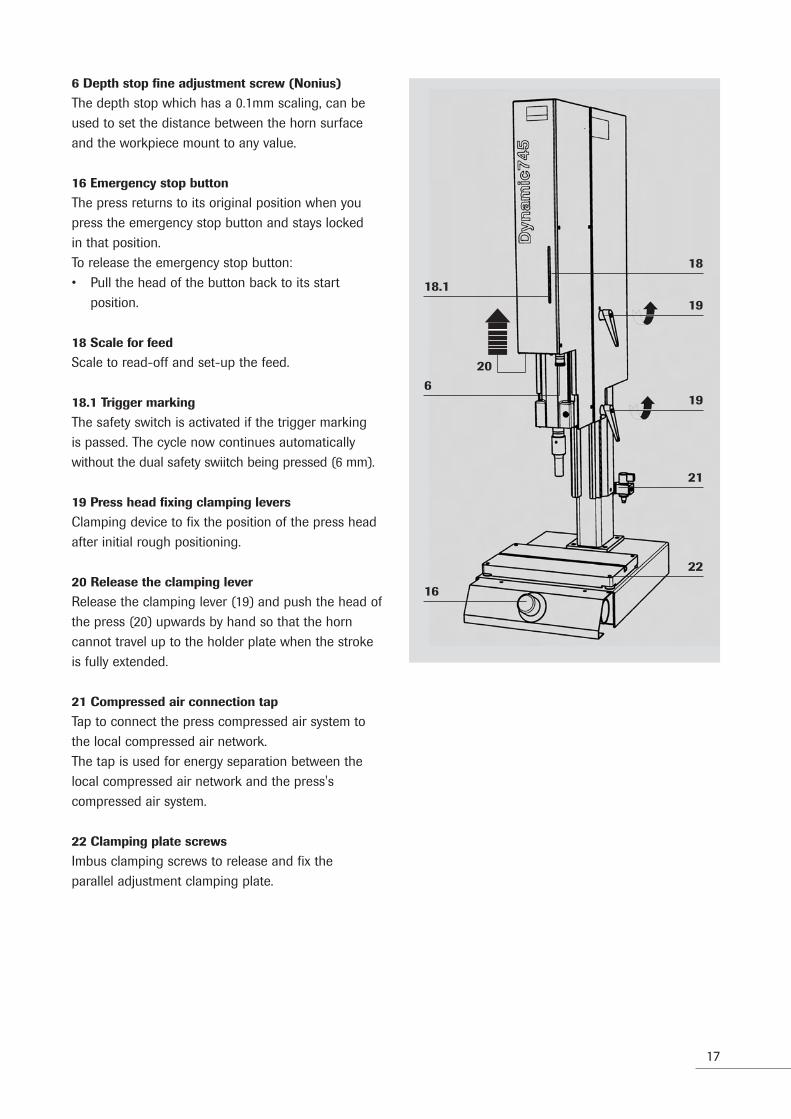
6 Depth stop fine adjustment screw (Nonius)
The depth stop which has a 0.1mm scaling, can beused to set the distance between the horn surfaceand the workpiece mount to any value.
16 Emergency stop button
The press returns to its original position when youpress the emergency stop button and stays lockedin that position.To release the emergency stop button:• Pull the head of the button back to its start
position.
18 Scale for feed
Scale to read-off and set-up the feed.
18.1 Trigger marking
The safety switch is activated if the trigger markingis passed. The cycle now continues automaticallywithout the dual safety swiitch being pressed (6 mm).
19 Press head fixing clamping levers
Clamping device to fix the position of the press headafter initial rough positioning.
20 Release the clamping lever
Release the clamping lever (19) and push the head ofthe press (20) upwards by hand so that the horncannot travel up to the holder plate when the strokeis fully extended.
21 Compressed air connection tap
Tap to connect the press compressed air system tothe local compressed air network.The tap is used for energy separation between thelocal compressed air network and the press'scompressed air system.
22 Clamping plate screws
Imbus clamping screws to release and fix the parallel adjustment clamping plate.
22
21
19
19
18
16
620
18.1

18
6.2 ACU Controller module
Program dialogue and result of the process aredisplayed numerically or graphically.During weld operation, the keyboard is locked so thatno changes can be made. Enquiries can however still be made.
The keyboard can be released by entering the corresponding PIN code, see chapter 7, “Programmingthe equipment”1 Display LCD 5.7" 1/4 VGA Monochrome Graphic
display2 Foil keyboard with 33 keys
6.3 The graphics and text display
Depending on the selected function mode, the graphic and text display shows the following information:
In programming mode:
The display is divided into 3 zones:• Program blocks (corresponding to the process
steps).• The parameter lines which belong to the current
block.• Status line: Describes the current status of the
program.• The function key assignment F1 to F5
1
2

19
In output mode after welding
Dynamics 745 with ACU offers the option of showing the last weldings in a graphic or a numericform on the screen.Display selection is done with key Taste F1.
Numerical display
All process-relevant data is shown on the screen inorder to analyse the weld. Additionally set limits areautomatically shown next to the numbers.[+]"Warning"[!]"Error"[*]"Limit exceeded"For more details check chapter 9.2, “The limits”.
The last 25 welds are stored and can be queriedusing F4 and F5.
Graphic display
The process graphic can be enlarged with F5ZOOM.To enlarge the graphic further, a corresponding timewindow can be selected with F5 which is maintaineduntil the equipment is switched off.

20
6.4 The Keyboard
The keyboard
After start-up, the controller is blocked against process data modifications. Enquiries can still bemade.The keyboard is broken down into 4 groups:
1 Function keys F1 - F5
They correspond to the functions shown on thebottom line of the screen.
2 Program help keys
Activated with PIN # 1000Mode:
Selects the corresponding operating modeParameter:
Process programming; data input.Limits:
For the input of max./min. time, travel and energyvalues.For more details check chapter 9, “Operating modes”PIN:
For the input of the corresponding PINcode numberAdjust:
Setup operation; lowering and raising the pressusing the dual safety switch to centre the lower tool.
1
3
25
4

21
Info:
To enter information such as project or tool info, aswell as the booster and horn amplifying factors forthe automatic amplitude calculation.
Database:
For the direct loading, storage and deletion of datasets. Individual applications can be stored in a 50 linedatabase.
Home:
Exits to the top program level.
3 Data input field:
Numbers 0-9; letters A-ZDEL: deleteEnter: confirmationFor parameter entries (programming entries), it is notnecessary to press «Enter».
4 Cursor field:
< > Cursor functions for writing and forchanging data.
< > Additional functions for changing pre-setvalues.
ESC: Exit step by step in reversed order.
5 System unit:
System test: Ultrasound oscillator testDisplay of stray power and frequency and the ACUsoftware version, press type, press software version,generator type and generator software version
Help: Informative help. Related to the active display.This key can also be used without the PIN.
<
<

22
7 Programming the equipment
The ACU generator controller system is divided overthe following levels:
Weld operation
Operation according to preset parameters withoutthe option of making any changes.
Set-up operation
Operation with the option of changing weld parameters (PIN 1000).
Initial operation
System initialisation PIN 3000To define the base settings.
The 'HOME' key brings you back to the top operating level "Weld operation"The 'ESC' key takes you back through the programlevels step by step.
7.1 Set-up
Setting the oscillation system up
Caution!
Power must be switched off at the generator before
starting to install the oscillation system.
1. Open screw (8) with the supplied Allen key (SW 6 mm)
2. Open the cover (7) of the converter housing3. Plug the HF plug in the converter HF connection
(23)
4. Insert the oscillation system into the converterhousing from the front
5. Replace the converter housing cover (7) and fixit in place with the Allen key
6. Screw the horn (9) in and tighten it with thespecial key (A) provided
Tightening torque 15 – 25 Nm.
The oscillation system is ready for operation.
PIN 7987
Weldoperation
Setupoperation
PINreset
Initialoperation
7
8
23
7
9

23
Booster change
The oscillation unit (25) can be mounted without ahorn in the reverse order in order to change thebooster.
Workpiece set-up
1. Estimate the height "H" necessary to insert andremove the workpiece.1 Horn2 Workpiece3 Workpiece mount4 Clamping table
2. Loosen the knurled screw (6.1) and set to heightH using the depth stop (6). Check against thescale (18).
3. Re-tighten the knurled screw.
1
H
2
3
4

24
4. Release the clamping lever (19) and push thehead of the press (20) upwards by hand so thatthe horn cannot travel up to the holder platewhen the stroke is fully extended.
5. Re-tighten the clamping lever.
Caution:
If the horn hasn't been set high enough, there is
a danger of collision.
Energieversorgung
1. Check whether the emergency stop switch is pulled out.
2. Open the hand operated compressed-air valve.
Caution! Don't touch the horn!
3. Swich the unit on with the POWER key.The ultrasound system carries out a self-test.You can call-up the Set-up operating mode withthe PIN code 1000 and the key ADJUST.The following standard values appear on thescreen:– Down travel speed: 3– Contact force: 100 N
Caution!
The workpiece mount with weld object must not
be under the horn.
4. The press is lowered at the pre-defined speed byusing the dual safety switch
20
19
19

25
5. Centre the workpiece mount with its weld objectunder the horn.
6. Set the press gently onto the weld object usingthe height adjustment.
7. Tighten the clamping lever.
8. Tighten the clamps (12) with the Allen key9. Partly tighten the two sides, check for correct
centering and then tighten fully.

26
10. Bring the press to the upper rest position usingthe dual safety switch.
11. Remove the weld object12. Lower the press again, using the dual safety
switch.13. Release the clamping lever and push the head of
the press downwards until the weldingstroke has reached the lowest position but thehorn does not yet touch the workpieceholder. The welding tool is thus not damaged.
14. The DATA BANK key gives access to a list ofstored data records.
15. Select the required application and press F2"Load data record".
16. Acknowledge the info "Machine setting" withEnter.
17. Press PARAMETER to check whether the storedparameters meet your requirements.
18. If you are working on a new application,download a similar one from the database with"Load data record".
19. Change the project name and the pressinformation under "Info".
If you are not familiar with weld technology, youshould now read the capital Weld technologycarefully.Modify the data record as required and fine tune itby testing it.
Note:
Never modify more than one parameter at a time,
otherwise it is very difficult to reconstruct which
modification had what effect.

27
7.2 Setting the clamping table up
The clamping table (13) was factory set to be parallelto the horn front face.If however, corrections need to be made, adjust theclamping table using the four parallel adjustingnuts (14).
Parallel adjustment:
1. Loosen the clamping screws (22) using the Allenkey (A).
2. Adjust the parallel adjusting nuts (14), as shownin the picture, to your requirements.
3. Once the adjustment is complete, re-tighten theclamping screws (22).
7.3 The weld cycle process
The cycle is started by pressing the start keys within0.3 seconds of each other. The power loss of theoscillating system is measured (system test). Thesolenoid valve is activated and the feed is loweredThe start keys must be held down until either thesafety switch (pointer beneath the red mark on thestroke scale) is passed or until the stop time haselapsed.
If the keys are released too early, the feed returns toits original position. An error message is issued.
The weld is started by the TRIGGER. Once theweld and the dwell time have elapsed, the feedreturns to its original position.In order to stop lighter workpieces hanging on to thehorn, an extra impulse can be added to the "Returnstroke" process step.

28
8 Weld technology
In order to guarantee the high quality and the lowtolerances of the ultrasound weld process, theparameters• Amplitude A [µm] as energy source and• Press force F [N] as the connection between the
plastics to be welded are of significance.
The more precise the control of these twoparameters, the better the reproducibility of thewelding process.
Plastics are often very different in terms of their melting behaviour. Special semi-crystalline thermo-plastics like PP or POM requires a high melting energy and then very quickly become liquid.The optimisation of the force and the amplitudeduring the weld process are very important in orderto be able to control the melting process.
With the Dynamic 745, RINCO ULTRASONICS AG hasdeveloped a welding unit which is definable in termsof force. Using sensors and a control system, thespeed, force and amplitude of the individual processphases are well balanced.Stop conditions can be preselected as time, energyor travel and then further restricted by applying limitsbased on quality classifications.
Plasticating conditionsForce (N)Amplitude A (µm)
Stop conditionsTime (s) Power W (Ws)Travel s (mm)

29
8.1 Process description
A weld cycle can be broken down into sevensequences:
The individual process steps
0 – 1 Pre stroke:Fast forward movement of the weld tool.
1– 2 Braking:Reduction of the downwards travel speed tocome to a gentle stop on the weld object.
2 – 3 Force build-up:A gradual build-up of press force up to thetrigger point.
3 – 4 Melting on:Start of the melting
4 – 5 Melting off:Continuing the polymer melting process.
5 – 6 Solidification:Firming up and cooling down of the meltedplastic under the influence of the timedapplication of force.
6 – 7 Return stroke:Fast return of the weld tool to the upper restposition.
Using the corresponding force and amplitudeprofiles, the cycle sequence then continues to run,controlled either by time or travel, according to theselected weld mode.
Stro
ke
Time

30
8.2 Dynamic 745 weld technology
Not every application needs a process point 4
By selecting the suitable weld mode, point 4 can besuppressed (see Figure)
The process graphic in the ACU display
ta: Melt-on time (TIMER MODE)sa: Melt-on travel (TRAVEL MODE)ts: Total weld time (TIMER MODE)ss: Total weld travel (TRAVEL MODE)
The force profile
Weld intensity is determined with each force timingchange. A high change in timing means a high weldintensity.
Changes can be made through parameter programming.The force development during the weld is always
positive. The important point here is the change intiming in [N/s]
Note:
The steeper the force process, the more
intensive the melting.
Welding with process point 4F (N)S (mm)P (%)
Travel s (mm)
Force F (N)
Power P (%)
t (ms)
t (ms)
t (ms)
(2)
put o
n
(3)
Trig
ger
Welding without process point 4
ta/sa (4)
ts/Ss (5)
F (N)
F (N)
Travel s (mm)
Force F (N)
Power P (%)
(2)
put o
n
(3)
Trig
ger
ts/Ss (5)
N/s
N/s
Force
Time

31
The minimum value is 0000 N/s, i.e. the forcedoesn't change over time, it remains constant.
Suggested inputs
Practical values for the timed force process.• Force build-up 2 – 3 100 – 200 N/s• Trigger 3 5 – 200 N• Melt on 3 – 4 100 – 250 N/s• Melt off 4 – 5 0 – 150 N/s
The braking speed must be adjusted accordingly forabnormally low trigger forces below 20 N.
F (N)
F (N)
Force setup value 000 (N/s)
2 3 4
2 3 4 5
t (s)
200 – 800
600 – 2000
0 – 800

32
9 Operating modes
9.1 Operating mode selection
You use the MODE key to select the operating mode,i.e. which stop conditions terminate the process.Basically, there are four options:• The preset time ts (Weld time)• The preset travel ss (Weld depth)• The preset energy Es (Weld energy)In order to monitor the process quality, quality windows can be set for time, travel and energy, withminimum and maximum values, using the keyfunction "Limits". A parts counter is also available.
9.2 The limits
The limits are used to help monitor quality. If a valuemoves outside the set limits, an error messageappears on the display. Exceeding the limits canbe defined as a "Warning" or an "Error".
Warning
Identification: In the Result display with [+], anexceeded value is marked with [*]
Error
Identification: In the Result display with [!].An exceeded value is marked with [*]If a value is exceeded, the press is blocked. It has tobe released with "Enter".The blocked position can optionally be selected as“up”, i.e., when at rest, or “down”, i.e., in the weldingposition. “Down” is only available to a reduced extentdue to the data communication. See also section 11.1 “System Initialisation”.
Possible limit values
• Time max / min • Travel max / min• Energy max / min • Power max. / min.Limits are set dependant on the stop condition. e.g.Time mode: Travel min/max or Energy min / maxlimits. Several limits can be set at the same time.

33
9.3 The individual modes
Time mode 1+2
Using this operating mode, the weld depth isreached based on time.
Cycle
The weld is triggered when the force trigger point isreached.
Welding continues from the trigger point until theend of the programmed time.
Time 1:
• US Start: Force trigger• US Stop: Time from trigger• Profile: Without "melting off"• Limits: Travel; Energy; Power max.
Time 2:
• US Start: Force trigger• US Stop: Time from trigger• Profile: With "melting off"• Limits: Travel; Energy; Power max.
The force changes can be entered in the samevalues, e.g. 800 N/s for an initial setting.A later modification of the melt-off condition maybring about improvements.
Trigger (US-Start)
F (N)
F (N)
F (t)
F (t)
t (s)
t (s)
Trig
gerf
orce
Trig
gerf
orce
ts
ts
ta

34
Travel mode difference 1+2
With this operating mode, exactly the same amountof material should be melted off during each weld.The melt-off depth (DEPTH) has the highest priority.The advantage of the differential method is thatcompensation is made continously, to allow for weldobjects with different dimensions.
Cycle
The weld is triggered when the Sensor trigger isreached. Welding continues until the DEPTH [ss] isreached.The actual travel value is measured at the end of thedwell time.
Travel diff 1:
• US Start: Force trigger• US Stop: Travel from trigger• Profile: Without "melting off"• Limits: Time; Energy; Power max.
Travel diff 2:
• US Start: Force trigger• US Stop: Travel from trigger• Profile: With "melting off"• Limits: Time; Energy; Power max.

35
Travel mode, Absolute 1+2
The weld object should have the same end dimen-sion after each weld with this operating mode. Theweld object's end dimension has highest priority.
Cycle
The weld is triggered after reaching the Sensortrigger. Welding continues until the DEPTH [ss] isreached. The DEPTH value [ss] is calculated from theupper end position. The actual travel value is measu-red after the end of the dwell time.
Travel absolute 1:
• US Start: Force trigger• US Stop: Travel from rest position• Profile: Without "melting off"• Limits: Time; Energy; Power max.
Travel absolute 2:
• US Start: Force trigger• US Stop: Travel from upper end position• Profile: With "melting off"• Limits: Time; Energy; Power max.

36
Travel mode, Absolute 3
The weld object should have the same end dimension after each weld with this operating mode.The weld object's end dimension has highestpriority.
Cycle
The weld is triggered after reaching the Traveltrigger[S1]. Welding continues until the DEPTH [S2]is reached. The DEPTH value [S2] is calculatedfrom the upper end position. The actual travel valueis measured after the end of the dwell time.
Travel absolute 3:
• US Start: Travel point• US Stop: Travel from rest position• Profile: Without "melting off"• Limits: Time; Energy; Power max.
Energy mode
The energy is totalised on a timed basis in energymode. A time limiting through “Limits” is to be stipulated to ensure consistent welding quality.In order to determine the effective welding energy,the system’s own energy loss has to be subtracted.This takes place by briefly operating the system inno-load operation either before or after the weldingprocess.The corresponding measuring interval can be set in«System-Init» (PIN 3000).Check chapter 11, “Init mode.

37
Cycles
The weld is triggered after the Force trigger is reached.The ultrasound stops once the necessary energy hasbeen reached.
Energy:
• US Start: Force trigger• US Stop: Energy• Profile: Without "melting off"• Limits: Time; Power max.

38
Programming
The weld process can be programmed step by stepwith the PARAMETER key Programming is structuredlike the steps described in Chapter 8.1.
0 –1 Work clearance stroke
Fast positioning of the horn• Programming in speed steps 1-9;• typical value: 5
1– 2 Braking
Freely selectable path value so that the path is setsuch that the Sonotrode is set down as gently aspossible on the object. Note that the speed reductionrequires a certain distance in itself.Note: Set the braking point to be high enough.• Programming in speed steps 1-9;• typical value: 2
2 – 3 Force build-up
The timed build-up of force until the ultrasonictrigger point (Force value in [N])• Programming in increase levels 0 – 800 [N/s];• typical value: 250 [N/s]
3 – 4 Melt on
The timed build-up of force after the ultrasonic trigger point• Programming in increase levels 0 – 800 [N/s];• typical value: 400 [N/s]
Amplitude
• Programming in steps 1 to 9Assuming that the amplification ratios of the boo-ster and the horn were entered correctly in theinfo field "Tool info", the system calculates thevalue in [µm]. Normally the force increase levelsand the amplitude will be selected high in thisstep (250 – 400 N/s).In the next step, melting off, the force increaselevels and the amplitude are more usuallyreduced.
Weld time
• Time from point 3 (trigger) to point 5 in [ms].
Weld travel
• Travel from point 3 (trigger) to point 5 in [mm].
Weld energy
• Energy from point 3 (trigger) until ultrasoundstop in [Ws] (only with "without melt-off" modes)
Stro
ke
Time

39
4-5 Melt off
The build-up of force over time and the amplitudeduring welding.• Programming in increase levels
0 – 800 [N/s]Note: Process item 4 can be suppressed by selectingwelding mode.
5-6 Solidification
Dwell force• Programming in units of force 0 – 745 [N]
Dwell timet• Programming of the corresponding time
interval [ms]
6-7 Return stroke
Return speed• Programming in steps1-9 [-]
So that the weld object doesn't stay hanging onthe horn, a shake impulse can be entered witha specified time duration.
• Programming as Time interval [ms]A time delay can also be defined (time delay fromthe start of "Return" to start of shakeimpulse).
To avoid the possibility of the weld object hanging onthe horn, an ultrasound "after-impulse" can be swit-ched on.• Delay time [ms]• After-impulse [ms]

40
10 Database / Data transfer
10.1 The Database
• To store 50 parameter sets• To load data into the weld press• For more detailed description and specification of
the data which is to be stored– Project info "Project Name"– Tool info "Tool numbers"– Amplification «Booster and horn
amplification factors»– Press info "Press position (height)
"Stop position (max. stroke)
10.2 Extended data evaluation
To evaluate welding data on a larger scale, the datacan be transmitted via RS 232 interface or Ethernetcard using TCP/ IP protocol to an industrial PC with master control.
The required programs "ACUcapture" and"ACUremote" can be obtained through RINCOULTRASONICS AG.When using other programs, information on required sequence modifications can be obtainedthrough RINCO.
ACUremote functions are described
• Observe online the results of the current weldingon the computer
• Check results of the last 25 weldings• Create any amount of process data and transfer
them to the ACU• Change system parameters with PIN 3000 using
the computer on the ACU

41
Description of ACUcapture functions
• Take over welding results online from the currentproduction using the computer. Selection can bemade with or without the graphic display of theprocess.
• Save welding result in a data bank.• Analyze welding result on the computer.• The following options are provided to minimise
the transmission time:– Expanding the transmission interval with
PIN 3000 – Setting the screen display to “Data” (F1).
This means that a performance graph does not appear on ACU capture.
Data transfer with data string
• Transfer process data via RS232 to externalprograms
• Programs are recommended by RINCO on request. Information on installation available insection 11, “Init mode”.

42
11 Init mode
11.1 System initialisation
PIN 3000 takes you to the Initialisation menu.Here you can set-up the background settings.
Init operation consists of two areas:• System parameter (F1)• Amplitude measurement (F3) to set desired
measurement values
Based on the screen assignments (in blocks andparameters) as used in the process programming, themenu is self-explanatory.You can select values such as "above" and "below"with the "<" and ">" keys.
11.2 System initialisation "Init mode"
System parameters
Settings
“Start mode”
Describes the trigger condition
Values:
“Manual”: For Rinco double-handed startwith CE safety.
“Automatic”: For triggering by an external sour-ce without additional safety que-ries (status controlled).
„Position in the case of an error“
Tool stop position in the case of an incorrect process.
Values:
“Above”: In the case of an error, the pressreturns to the upper rest position.
“Below”: The press remains in the lowerposition in the case of an errorand can be returned with “Enter”.
Default value: “Above”The “down” position is only possible in the followingconfiguration due to the data communication:• Error time max. • Path diff 1 and 2 sections 1,2,3• Time modes 1,2 • Energy mode• Error path max. • Time modes 1,2• Energy mode

43
Horn
For identifying and modifying the acoustic characteristics
“Max. power loss”:
Power limit while idling. If thevalue is exceeded, an error isdisplayed.
Values: 10 to 40 in [%]
Default value: 10 [%]
"Measuring performance loss PL":
Values: "Before" "After"Default value: "Before"
“Pv measurement interval”:
Power loss measurement interval at process startto correct the weld energy.Values: 0000 to 9999.Example: 00001 Measurement before each
welding.00010 Measurement before eachtenth welding.00000 No measurement.
Default value: 0001
“Soft start”:
To protect difficult horns during initial oscillation, thestart ramp-up can have different timing values.
Values: 020 to 200 [ms]Larger value for heavy horns.
Default value: 020
“Soft stopping time”:
A soft stopping time can be set to protect the oscillator system. The ultrasound process is not swit-ched off at once when using soft stopping.The amplitude is reduced in a linear fashion from thecurrent amplitude value down to 0. Frequency regula-tion is switched off during soft stopping.
Values: 000 to 050 in [ms]Default value: 000

44
Screen
“Screen”:
To set the screen colours.
Values: “white / black”“black / white”
Default setting: “white / black”
Example: Black background, white text
Values: 000 to 999
Standard setting: 200
“Telnet messages”:
Status messages via Ethernet.
Values: On; Offthe "On" setting requires theinstallation of a modem.
Default value: ”Off”
PIN codes
To define the various codes individually.Values: 0000 to 9999
Standard values: Set-up operation: PIN 1000Init mode: PIN 3000
Please make a note of any modified codes. If you
forget them, only a member of the Rinco Service
Team can set them back to their standard settings.
Date/Time
To set the date and time.Values:
“System time”:
Internal system clock in hours and minutes.
“System Date”:
Internal system date as year, month, day.
Change settings by overwriting them.

45
Country setting
To set country-specific values.
"Travel unit”:
To scale the depth setting.
Values: “mm” or “inch”
Default value: “mm”
“System language”:
Dialogue text setting.Values: German; English; French; Italian,
Spanish;
Default value: English
RS 232 Kom.
Setting the serial interface.
“Baudrate”:
Transfer rate in bits
Definition of the RS232 start bit
To modify the interface
Networking
Communication settings for Ethernet.
“IP address”:Default value: 192.168.0.80
“Subnetwork mask”:Default value: 255.255.255.0
“Default gateway”:Default value: 192.168.0.1.

46
Miscellaneous
“Overwrite standard data records”:
Releasing the last ten database lines that can beoccupied with RINCO default data records.
Values: “Off”; “On”Standard value: “Off" meaning that the last
10 memory locations are blocked.
“External database changeover”:
Allow database changeover via RS232
Values: “On”, “Off”
Standard value: “Off”
"Sound protection box":
To initialize the sound protection box.Values: "On"; "Off"Standard value: "Off"
Data string
For the direct transmission of welding data to anexternal system.
“Transmission”:
RS 232
Values: “On”; “Off”
Default value: “Off”
“Interval”:
Values: “0000”; “10,000”
Default value: “00001”
“Interval ACU capture/ACU remote”:
Values: “0000”; “10,000”
Default value: “00001”

47
11.3 Description of data string
11.3.1 Brief description
For quality control and traceability of welded parts,programs are often used that can record therequired data via an interface. This concept also hasto be available with the ACU. For this reason, it hasto be possible to output a data string at the end ofthe welding cycle via the serial interface (RS232). Itmust be possible to switch the output on and off.Similarly, it has to be possible to determine the out-put interval.
11.3.2 Structure of the data string
The following parameters are shown in the sequencelisted and are separated by a semi-colon (;). At theend of the data string, a <CR> is sent.
• Project name • Database number• Welding mode • Date• Time • Piece counter• Reject counter • Energy• Max. power [W] • Max. power[%]• Power loss [W] • Power loss [%]• Welding time • Welding travel• Frequency • Error code• <CR>
11.3.3 Example of an output
Project name; database number; welding mode; date;time; piece counter; reject counter; energy; max.power [W]; max. power [%]; power loss [W]; powerloss [%]; welding time; welding travel; frequency; error code

48
12 General maintenance work
12.1 Cleaning the equipment
Caution!
Cleaning and maintenance work should only be car-
ried out by suitable trained personnel. Before star-
ting maintenance work, you should ensure that all
energy sources (power supply, compressed air etc.
) have been disconnected or disabled.
Please note: Never use aggressive cleaning agents
to clean the keyboard or screen.
The multi press and the generator don't require
any particular maintenance.
If the following elements are cleaned regularly howe-ver :• Feed unit,• Clamping table (13),• Workpiece mount (11),• Horn (9),this guarantees a long and problem-free operationof the welding press system.
12.2 Clamping table
Clean the clamping table (13) daily.
12.3 Pneumatics unit
When work is completed, move the compresed-airtap (21) into the transverse position to avoid the needfor maintenance.
12.4 Lubrication system
Maintenance-free.
12.5 Generator
You should ensure that the generator display isalways kept clean

49
12.6 Oscillation system
Danger!
Because of high voltages, work on the oscillation
system and the converter housing must only be
carried out after the unit has been removed from
the power.
Avoid contact with the HF socket on the converter.
Don't connect any measuring device to the
converter's HF socket.
Even after switching the generator off, the
converter still has a power loading.
12.7 Screwed connections
The converter (24), booster (25) and horn(9) arescrewed into each other.Tightening torque: 15 – 25 Nm
Black marks on the surface of the booster (25) or thehorn (9) can easily be removed.
1. Lay a polishing cloth on a flat surface2. Slide the blackened surfaces over the cloth.

50
12.8 Error messages and their correctionduring power on
Error Possible causes Error correction
Generator is not switching on – No power supply – Connect to the power– Faulty fuse – Check the fuse
12.9 Error messages and their correction
Errors on the machine side are displayed in aself-explanatory way on the ACU displayError situations should only be corrected by suitablytrained personnel. If you are unsure of what to do,please contact your Service Centre or themanufacturers direct.
12.10 Error messages and their correctionduring set-up and welding
Error Possible causes Error correction
Horn is lowered but the – Trigger set too high – Set the trigger lowerultrasonic doesn't start up – Trigger defective – Contact your RINCO service
centre
In spite of increasing the weld – Depth stop is set too low – Set the depth stop highertime, the parts are not weldedany closer together
Error messages of the generatorare confirmed by Enter key.
51
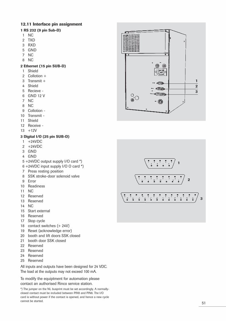
12.11 Interface pin assignment1 RS 232 (9 pin Sub-D)1 NC2 TXD3 RXD5 GND7 NC8 NC
2 Ethernet (15 pin SUB-D)1 Shield2 Collotion +3 Transmit +4 Shield5 Recieve -6 GND 12 V7 NC8 NC9 Collotion -
10 Transmit -11 Shield12 Receive -13 +12V
3 Digital I/O (25 pin SUB-D)1 +24VDC2 +24VDC3 GND4 GND5 +24VDC output supply I/O card *)6 +24VDC input supply I/O O card *)7 Press resting position8 SSK stroke-door solenoid valve9 Error
10 Readiness11 NC12 Reserved13 Reserved14 NC15 Start external16 Reserved17 Stop cycle18 contact switches (+ 24V)19 Reset (acknowledge error)20 booth and lift doors SSK closed21 booth door SSK closed22 Reserved23 Reserved24 Reserved25 Reserved
All inputs and outputs have been designed for 24 VDC.The load at the outputs may not exceed 100 mA.
To modify the equiptment for automation pleasecontact an authorised Rinco service station.*) The jumper on the NL busprint must be set accordingly. A normally-closed contact must be included between PIN5 and PIN6. The I/Ocard is without power if the contact is opened, and hence a new cyclecannot be started.
123
1
2
3

52
12.12 Generator fusesFuses are to be found on the following components:
Power boxAll fuse dimensions: 5 x 20 mm.
10.13 List of the generator fuses
900 W / 1500 W / 2000 W / 3000 W
Generator Power box
F1 F2
ACU 35-900 6.3 A/T 6.3 A/T
F1 / F2

53
13 Service Addresses
If you experience problems with welding or technicalfaults with the equipment, please contact theTechnical Customer Service of RINCO ULTRASONICSAG, who will be pleased to help you.For an efficient response our Customer Service requires the following information:
– A precise description of the technical fault or welding problem.
Our address:
RINCO ULTRASONICS AGIndustriestrasse 4CH-8590 RomanshornSwitzerland
National callsTel. 071 466 41 00Fax 071 466 41 01
International callsTel. ++41 71 466 41 00Fax ++41 71 466 41 [email protected]

Dat
eC
arri
ed o
ut w
ork
Pers
on in
cha
rge
Not
e
54

55
Dat
eC
arri
ed o
ut w
ork
Pers
on in
cha
rge
Not
e

56
RINCO ULTRASONICS AG
Industriestrasse 4CH-8590 Romanshorn 1Switzerland
Tel. +41 71 466 41 00Fax +41 71 466 41 01
CR
ES
T G
RO
UP
CO
MP
AN
Y