Embed Size (px)
Citation preview
Instrucciones de servicio
Conservar para uso poster ior !
ECO.torch Interface de giro
refrigerado por gas
Operation manual
Keep in secure area for future reference!
ECO.torch Rotary interface
gas cooled
Betriebsanleitung
Für künftige Verwendung aufbewahren!
BA-0062
ECO.torch Drehmediumgasgekühlt
S C H W E I S S E N W E L D I N G W E L D I N GS O L D A D U R A S C H W E I S S E N
AnwendungsbeispielSample application
Ejemplo de aplicación
DIX RET 341 FDIX RET 341 S
DIX RET 341 F/WB 1DIX RET 341 S/WB 1

Copyright © 2014 DINSE G.m.b.H., Hamburg.
Jede Art der Vervielfältigung sowie der Übersetzung, auch auszugsweise, darf ohne schriftliche Genehmigung der DINSE G.m.b.H. nicht reproduziert oder unter Verwendung elektronischer Systeme gespeichert, verarbeitet oder verbreitet werden.
These instructions or excerpts thereof shall not be duplicated, translated or reproduced, nor shall they be stored, processed, transmitted or distributed by any electronic means without the prior written permission of DINSE G.m.b.H.
Ningún tipo de copia y de traducción, incluso parcial, de estas instrucciones, se puede reproducir sin autorización escrita de DINSE G.m.b.H., ni almacenar, procesar y divulgar utilizando sistemas electrónicos.
ECO-RET-341-BA/D15 Änderungenvorbehalten!/Wereservetherighttomakechanges!/Sereservaelderechodeintroducirmodificaciones!
Antes de la puesta en marcha, leer sin falta estas instrucciones de servicio,
para garantizar un manejo seguro del producto DINSE. El explotador debe facilitar al operario estas instrucciones de servicio y asegurarse de que el operador las lea y las comprenda.
Guardar estas instrucciones de servicio de maneratalqueesténlosuficientementepro-tegidas. En el área de trabajo, dejar indicado de manera bien visible el lugar en el que se conservan las instrucciones.
Estos productos satisfacen las directivas2004/108/EG – CEM2014/35/EU – De baja tensiónIEC 60974-7 – para equipos de solda-
dura eléctrica por arco (antorchas)
IEC 60974-10 – Para equipos de soldadu-ra eléctrica por arco (Compatibilidad electro-magnética (CEM)
INFO
Durante la instalación, el funcionamien-to y las tareas de mantenimiento de la fuente de corriente para soldadura robotizada debe cumplirse con la nor-mativa técnica y las disposiciones para la prevención de accidentes.
Read these operating instructions care-fully before operating this product. The
owner of the product must make this operating manual available to each operator and ensure the operator has read and fully understands the instructions prior to use.
Keep the operating manual in a safe place for future reference. Prominently display singage in the working area to clearly specify where the manual is kept.
These products comply with2004/108/EC – EMC directive2014/35/EU – Low voltage directiveIEC 60974-7 – Electric arc welding
equipment (torch)IEC 60974-10 – Electric arc welding
equipment (Electromagnetic com-patibility EMC)
INFO
The operator must comply with techni-cal standards and accident prevention guidelines during installation, operation and maintenance of the robot welding power source.
Diese Betriebsanleitung unbedingt vor Inbetriebnahme lesen, um einen
sicheren Umgang mit dem DINSE-Produkt zu garantieren. Der Betreiber muss dem Bediener diese Betriebsanleitung zugängig machen und sich vergewissern, dass der Bediener sie gelesen und verstanden hat.
Die Betriebsanleitung für den späteren Ge-brauch aufbewahren. Einen Hinweis auf den Ablageort gut sichtbar im Arbeitsbereich hin-terlassen. Bei Weiterverkauf des Gerätes muss die Betriebsanleitung mit ausgehändigt werden.
Diese Produkte erfüllen die2004/108/EG – EMV - Richtlinie2014/35/EU – NiederspannungsrichtlinieIEC 60974-7 – Lichtbogenschweiß-
einrichtungen (Brenner)IEC 60974-10 – Lichtbogenschweiß-
einrichtungen (Elektromagnetische Verträglichkeit EMV)
INFO
Bei der Installation, beim Betrieb und der Wartung müssen aus Betreibersicht technische Normen und Unfallverhü-tungsvorschriften eingehalten werden.
S C H W E I S S E N W E L D I N G W E L D I N GS O L D A D U R A S C H W E I S S E N
3

El ín
dice
5. Puesta en marcha 185.1 Montaje en el brazo del robot 18
5.1.1 Herramientas y componentes 185.1.2 Montaje de la brida de adaptación 195.1.3 Montaje del devanador de hilo 205.1.4 Montaje de la pistola de soldadura en el
devanador de hilo 215.1.5 Montaje de la pistola en el brazo del robot
(sexto eje) 235.1.6 Montaje de la interfaz rotativa 255.1.7 Montaje del cabezal de pistola 295.1.8 Inserción de la espiral de guía de hilo 305.1.9 Montaje del cable del sensor de toberas de gas 345.1.10 Comprobación de recorridos 35
6. Indicaciones de mantenimiento 366.1 Cambio de la espiral de guía de hilo 386.2 Reparaciones en el juego de soldadura 397. Solución del problema 40
1. Introducción 61.1 Declaración de conformidad DIX RET 341 F+S 71.2 Declaración de conformidad DIX RET 341 F WB 1 81.3 Declaración de conformidad DIX RET 341 S WB 1 92. Seguridad 102.1 Símbolos empleados 102.2 Empleo adecuado 112.3 Riesgos existentes al emplear adecuadamente el producto 122.4 Operarios autorizados 142.5 Derecho de garantía 142.6 Transporte y embalaje 152.7 Reciclaje/Eliminación de basura 15
2.7.1 Países de la UE 152.7.2 En otros países 15
3. Datos técnicos 164. Instrucciones de uso 17
Tabl
e of
Con
tent
s
5. Installation 185.1 Mounting on a robot arm 18
5.1.1 Tools and components 185.1.2 Mountingoftheadapterflange 195.1.3 Mounting the wire feeder 205.1.4 Mounting the torch set on the wire feeder 215.1.5 Mounting the torch set on the robot arm (6th axis) 235.1.6 Mounting the rotary interface 255.1.7 Mounting the torch head 295.1.8 Insert liner 305.1.9 Mount the gas nozzle sensor cable 345.1.10 Check travel 35
6. Maintenance instructions 366.1 Changing the liner 386.2 Repairing torch sets 397. Troubleshooting 40
1. Introduction 61.1 EC-Declaration of conformity DIX RET 341 F+S 71.2 EC-Declaration of conformity DIX RET 341 F WB 1 81.3 EC-Declaration of conformity DIX RET 341 S WB 1 92. Safety 102.1 Symbols used in operating manual 102.2 Intended purpose 112.3 Safeguarding against potential hazards during regular usage 122.4 Authorized operators 142.5 Limited Warranty 142.6 Transportation and packaging 152.7 Recycling / Disposal 15
2.7.1 EU countries 152.7.2 Other countries 15
3. Technical Data 164. Instructions for use 17
Inha
ltsve
rzei
chni
s
1. Einleitung 61.1 EG-Konformitätserklärung DIX RET 341 F+S 71.2 EG-Konformitätserklärung DIX RET 341 F WB 1 81.3 EG-Konformitätserklärung DIX RET 341 S WB 1 92. Sicherheit 102.1 Verwendete Symbole 102.2 Bestimmungsgemäße Verwendung 112.3 Gefährdungen bei bestimmungsgemäßer Verwendung 122.4 Zugelassene Bediener 142.5 Gewährleistungsanspruch 142.6 Transport und Verpackung 152.7 Recycling / Entsorgung 153. Technische Daten 164. Anwendungshinweise 17
5. Inbetriebnahme 185.1 Montage am Roboterarm 18
5.1.1 Werkzeuge und Bauteile 185.1.2 MontagedesAdapterflansches 195.1.3 Montage des Drahtvorschubs 205.1.4 Montage der Schweißgarnitur am Drahtvorschub 215.1.5 Montage der Schweißgarnitur am Roboterarm
(6. Achse) 235.1.6 Montage des Drehmediums 255.1.7 Montage des Pistolenkopfes 295.1.8 Drahtführungsspirale einführen 305.1.9 Gasdüsensensorkabel montieren 345.1.10 Verfahrwege prüfen 35
6. Wartungshinweise 366.1 Wechsel der Drahtführungsspirale 386.2 Schweißgarnitur reparieren 397. Störungsbehebung 40
S C H W E I S S E N W E L D I N G W E L D I N GS O L D A D U R A S C H W E I S S E N
4

El ín
dice
Apéndice G 69Devanador de hilo ABB-Kemppi 69
Apéndice H 72Corte correcto de la espiral de guía de hilo 72
Apéndice J 73Montaje Fanucroboter con Solution Arm 73
Apéndice A 42Montaje de la protección frente a pandeo en Motoman-Yaskawa-Robots 42
Apéndice B 43Montaje de la platina adaptadora en ABB-Robots 43
Apéndice C 44Puertos del módulo de protección DIX REMO 101 44Puerto asignación DIX REMO 101 45Esquema de conexión REMO 101 con gas de protección 46Esquema de conexión REMO 101 con aire comprimido (versión 1) 47Esquema de conexión REMO 101 con aire comprimido (versión 2) 48Conexión REMA 49
Apéndice D 50Montaje de la interfaz rotativa sin sensor de toberas de gas 50
Apéndice E 52Interfaz rotativa con freno de hilo integrado 52
Apéndice F 68Power Pin 68
Tabl
e of
Con
tent
s
Appendix G 69ABB-Kemppi-Wire feed 69
Appendix H 72Correct cutting of liners 72
Appendix J 73Mounting on a Fanuc robot with Solution Arm 73
Appendix A 42Mounting the bend protection at Motoman-Yaskawa-Robots 42
Appendix B 43Mounting theaddingadapterflangeatABB-Robots 43
Appendix C 44Ports of the protection module DIX REMO 101 44Port assignment DIX REMO 101 45Connection plan REMO 101 with shielding gas 46Connection plan REMO 101 with compressed air (Version 1) 47Connection plan REMO 101 with compressed air (Version 2) 48Connection REMA 49
Appendix D 50Complete mounting of rotary interface without gas nozzle sensor 50
Appendix E 52Rotary interface with integrated wire brake 52
Appendix F 68Power Pin 68
Inha
ltsve
rzei
chni
s
Anhang A 42Montage des Knickschutzes bei Motoman-Yaskawa-Robotern 42
Anhang B 43MontagedesZusatzadapterflanschesbeiABB-Robotern 43
Anhang C 44Anschlüsse des Schutzmoduls DIX REMO 101 44Anschlussbelegung des Schutzmoduls DIX REMO 101 45Anschlussplan REMO 101 mit Schutzgas 46Anschlussplan REMO 101 mit Druckluft (Version 1) 47Anschlussplan REMO 101 mit Druckluft (Version 2) 48Anschluss REMA 49
Anhang D 50Drehmedium ohne Gasdüsensensor fertig montieren 50
Anhang E 52Drehmedium mit integrierter Drahtbremse 52
Anhang F 68Power Pin 68
Anhang G 69ABB-Kemppi-Drahtvorschub 69
Anhang H 72Korrektes Schneiden von Drahtführungsspiralen 72
Anhang J 73Montage bei Fanucroboter mit Solution Arm 73
S C H W E I S S E N W E L D I N G W E L D I N GS O L D A D U R A S C H W E I S S E N
5

Usted ha adquirido un producto de calidad de DINSE.Leagradecemosporlaconfianzadepositada.
Este producto, fabricado con el mayor cuidado, es controlado continuamente durante la fabri-cación. Las funciones de cada componente se prueban antes y después del montaje.
Pruebas paralelas a la fabricación, materiales perfectamente acordes entre sí y una produc-ción mediante maquinaria especializada de alta calidad caracterizan a este accesorio de soldadura de gran exigencia técnica.
Por favor, póngase en contacto con el dis-tribuidor DINSE de su país, si usted tiene cualquier pregunta o solicitud de los equipos y suministros.
1. Introducción
You have purchased a quality product from DINSE. Thankyouforyourconfidenceinourproducts.
This product was manufactured under constant supervision during production. Each compo-nent is tested for proper functionality before and after assembly.
This product is a technically-sophisticated welding accessory made with precision-mat-ched materials and manufactured on special high-grade machines.
Please contact the DINSE distributor of your country, if you have any questions or requests regarding equipment and supplies.
1. Introduction1. Einleitung
Sie haben ein Qualitätsprodukt der DINSE gekauft. Wir danken Ihnen für das entgegengebrachte Vertrauen.
Dieses, mit größter Sorgfalt hergestellte Pro-dukt, wird während der Fertigung laufend kon-trolliert. Jede Komponente wird vor bzw. nach der Montage auf seine Funktionen getestet.
Fertigungsbegleitende Prüfungen, genau auf-einander abgestimmte Werkstoffe und die Her-stellung auf hochwertigen Spezialmaschinen charakterisieren dieses technisch anspruchs-volle Schweißzubehör.
Bitte setzen Sie sich mit dem DINSE-Ver-triebspartner ihres Landes in Verbindung, wenn Sie Fragen oder Wünsche bzgl. Zubehör und Ausstattung haben.
S C H W E I S S E N W E L D I N G W E L D I N GS O L D A D U R A S C H W E I S S E N
6
: :
D I N S E G . m . b . H . Tarpen 36 • D-22419 Hamburg
Tel. +49 (0)40 658 75-0Fax +49 (0)40 658 75-200
[email protected] – www.dinse.eu
Kontakt:Contact:El contacto:
Kontakt für den US-Markt:Contact for the U.S. market:Contacto para el mercado de EE.UU.:
D I N S E I n c . 8 3 0 D i l l o n D r i v e
[email protected] – www.dinse-us.com
W o o d D a l e , I L 6 0 1 9 1 U S APhone. 517 416 5294 – Fax. 888 896 4871
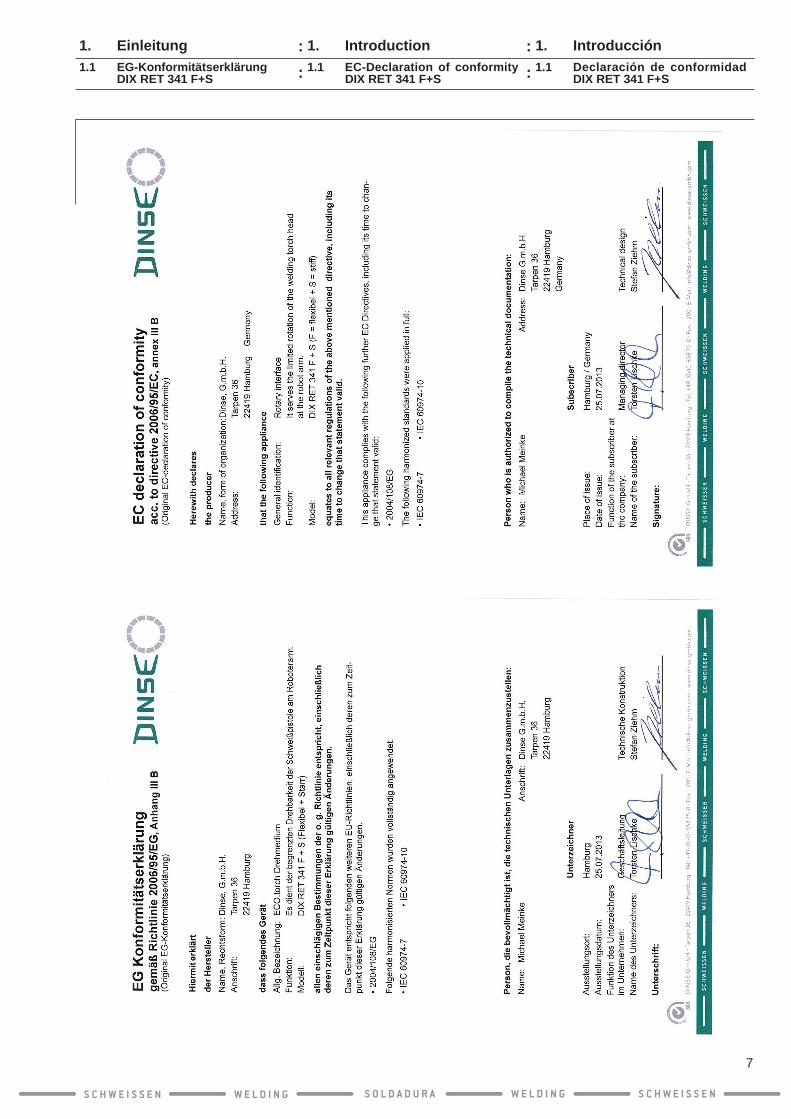
1. Introducción1.1 Declaración de conformidad
DIX RET 341 F+S
1. Introduction1.1 EC-Declaration of conformity
DIX RET 341 F+S
1. Einleitung1.1 EG-Konformitätserklärung
DIX RET 341 F+S
S C H W E I S S E N W E L D I N G W E L D I N GS O L D A D U R A S C H W E I S S E N
7
::
::
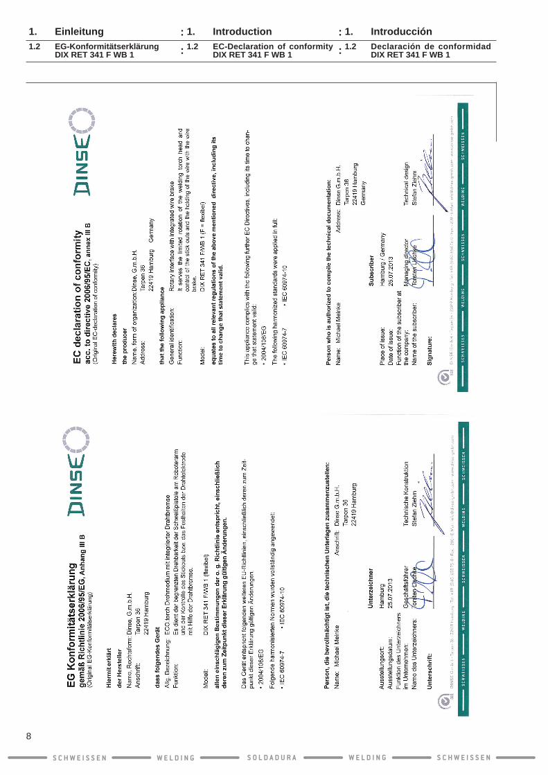
1. Introducción1.2 Declaración de conformidad
DIX RET 341 F WB 1
1. Introduction1.2 EC-Declaration of conformity
DIX RET 341 F WB 1
1. Einleitung1.2 EG-Konformitätserklärung
DIX RET 341 F WB 1
S C H W E I S S E N W E L D I N G W E L D I N GS O L D A D U R A S C H W E I S S E N
8
::
::

1. Introducción1.3 Declaración de conformidad
DIX RET 341 S WB 1
1. Introduction1.3 EC-Declaration of conformity
DIX RET 341 S WB 1
1. Einleitung1.3 EG-Konformitätserklärung
DIX RET 341 S WB 1
S C H W E I S S E N W E L D I N G W E L D I N GS O L D A D U R A S C H W E I S S E N
9
::
::

2. Seguridad2.1 Símbolos empleados
Todos los productos DINSE están equipados con dispositivos de protección. Se construyen a prueba de fallas empleando la tecnología más avanzada y según reglas técnicas de seguridad reconocidas. En caso de empleo inadecuado o inapropiado, puede ponerse en peligro:
● El cuerpo y la vida del operario ● El producto y otros bienes del explotador y
● El t raba jo e f i c ien te de l p roduc to
Se trata de su seguridad!En estas instrucciones de servicio se utilizan los siguientes símbolos:
Símbolos de peligro y de prohibición
Peligro por descarga eléctrica
Peligro por ruido con alto nivel de presión sonora
Peligro de heridas en manos
Peligro de de-stellos y en-candilamiento
Peligro de incendio
Peligro de explosión
Peligro por materiales tóxicos
Peligro por tanque de gas
Peligro de quemadu-ras por
partes calientes
Peligro de virutas
Peligro de daños materiales o de situación riesgosa
Colocarse la protec-ción para los ojos!
Antes de de-stapar, retirar siempre el enchufe!
Otros símbolos
INFO
Información técnica y recomenda-ciones de uso
● Listado
Se requiere que ejecute una acción
1. 2.
Realice las acciones en el orden descripto.
Ajustar los tornillos con el momento de torsión especificado
No se encu-entra enhogar basuraDeseche!
2. Safety2.1 Symbols used in operating
manual
All DINSE products are equipped with safety devices. They are manufactured using the latest technology and in accordance with ap-proved safety regulations. WARNING! Improper or unauthorized use carries the risk of:
● Causing harm to Operator‘s life and limb ● Causing harm to the product itself and/or other property
● PreventingefficientoperationoftheproductWe are concerned about your safety!The following symbols are used in this opera-ting manual:
Hazard warnings and instructions
Danger of electric shock
Danger of ex-cessive noise and sound-pressure levels
Danger of hand injury
Danger of blinding and electrical discharge
Danger offire
Danger of explosion
Danger of poisoning
Danger posed by gas cylinder
Burn hazard due to hot parts
Danger from flyingchips
Danger of material damage or unsafe conditions
Wear eye protec-tion!
Always unplug before opening!
Other symbols
INFO
Technical information and tips
● List
Operator’s Action is Required.
1. 2.
Perform the necessary steps in the prescribed sequence for no. items.
Tighten the screw firmlytotheprescribed torque
Do not discard in the household waste.
2. Sicherheit2.1 Verwendete Symbole
A l l e D I N S E - P r o d u k t e s i n d m i t Schutzeinrichtungen ausgerüstet. Sie sind nach dem Stand der Technik und den aner-kannten sicherheitstechnischen Regeln be-triebssicher gebaut. Bei unsachgemäßer oder nicht bestimmungsgemäßer Verwendung ist mit möglichen Risiken zu rechnen für:
● Leib und Leben des Bedieners ● Das Produkt und andere Sachwerte des Betreibers
● DieeffizienteArbeitdesProdukts.
Es geht um Ihre Sicherheit!In dieser Betriebsanleitung werden folgende Symbole verwendet:
Gefahren- und Gebotssymbole
Gefahr durch Strom-schlag
Gefahr durch Lärm mit hohem Schalldruck-pegel
Gefahr von Handver-letzungen
Blend- und Verblitzungs-gefahr
Brandge-fahr
Explosions-gefahr
Gefahr durch gif-tige Stoffe
Gefahr durch Gasflasche
Gefahr von Verbren-nungen durch heiße Teile
Gefahr durch umherflie-gende Späne
Gefahr von Sachschaden oder gefährliche Situation
Augen-schutz tragen!
Vor dem Öffnen immer den Netzste-cker ziehen!
Weitere Symbole
Technische Informati-onen und Anwen-dungstipps
● Auflistung
Sie werden zu einer Handlung aufgefordert.
1. 2.
Handlungen in der be-schriebenen Reihenfolge ausführen.
Schraube mit angege-benen Dreh-moment fest schrauben
Nicht im Hausmüll entsorgen!
INFO
S C H W E I S S E N W E L D I N G W E L D I N GS O L D A D U R A S C H W E I S S E N
10
::
::

Interface de giro sirve sólo al desarrollo de material adicional en caso de soldadura térmica y soldadura eléctrica.
Los Interface de giro no es adecuado para uso al aire libre! Interface de giro se adecua, según modelo y equipamiento, para la soldadura de:
● Aceros no aleados
● Aceros escasamente aleados
● Aceros altamente aleados
● Aleaciones de aluminio, magnesio, cobre y níquel
● Espesores pequeños y grandes
Interface de giro trabaja con el proceso MIG y MAG y está diseñado para una tensión en vacío máxima de 113V (valor del vértice).
La fuente de energía eléctrica que abastece al juego de soldadura debe cumplir estas condiciones.
Verifique estas condiciones antes de laprimera puesta en marcha.
Por motivos de seguridad, DINSE prohíbe refaccionesymodificacionesarbitrariasInter-face de giro.
2. Seguridad2.2 Empleo adecuado
The only purpose of the rotary interface is to supply additives during welding and soldering processes.
The rotary interface is not not suitable for outdoor use!
Depending on the particular model and availa-ble features, the rotary interface is suitable for welding the following materials:
● Unalloyed steels
● Low-alloy steels
● High-alloy steels
● Aluminium, magnesium, copper and nickel-based alloys
● The above named materials can be thick or thin
The rotary interface employs the MIG/MAG techniques, and is designed for a maximum open-circuit DC voltage of 113V (peak value).Priortofirstuse,alwayschecktoensurethepower supply to the torch complies with this specification!
Prior to first use, check for compliancebefore using the equipment.
For safety reasons, DINSE does not permit, authorize, or recommend any third-party mo-difications or post-manufacturing alterationsto the torch.
2. Safety2.2 Intended purpose
Das Drehmedium dient nur der Förderung von Zusatzstoffen beim Schweißen und Löten.
Das Drehmedium ist nicht für den Gebrauch im Freiengeeignet!
Das Drehmedium eignet sich, je nach Modell und Ausstattung, für das Schweißen von:
● Unlegierten Stählen
● Niedrig legierten Stählen
● Hoch legierten Stählen
● Aluminium-, Magnesium-, Kupfer- und Nickelbasislegierungen
● Kleine bis große Materialstärken
Das Drehmedium arbeitet mit dem MIG bzw. MAG-Verfahren und ist für maximal 113V Leerlaufgleichspannung (Scheitelwert) aus-gelegt.
Die Stromquelle, die das Drehmedium versorgt, muss diese Bedingung erfüllen!
Prüfen Sie diese Bedingung vor der ersten Inbetriebnahme.
Aus Sicherheitsgründen untersagt DINSE eigenmächtige Umbauten und Veränderungen des Drehmediums.
2. Sicherheit2.2 Bestimmungsgemäße
Verwendung
S C H W E I S S E N W E L D I N G W E L D I N GS O L D A D U R A S C H W E I S S E N
11
::
::
2. Seguridad2.3 Riesgos existentes al emplear
adecuadamente el producto
ATENCIÓN: Atender las normas de preven-ción de accidentes!La inobservancia de las siguientes medidas de seguridad puede poner en riesgo su vida!
ADVERTENCIA!
La radiación del arco voltai-co puede dañar y quemar la piel!
Jamás mirar con ojos descubiertos en el arco voltaico.Antes de soldar, colocarse la ropa pro-tectora reglamentaria (por ej. guantes protectores).Utilizar casco o escudo protector para soldaduraconfiltrosolarapropiado.
PELIGRO!
Una descarga eléctrica pue-de llevar a la muerte!
En todos los trabajos de control y de mantenimiento, se debe retirar el enchufe de alimentación de red y se debe asegurar que nadie conecte el abastecimiento de tensión durante el mantenimiento!Colocar siempre la pistola de soldadura y el soporte de electrodos en un lugar aislado.No utilizar cables de pistolas, de tierra o de abastecimiento con aislamiento dañado.Los daños deben ser reparados de inmediato por un electricista capacitado!
ADVERTENCIA!
Los vapores y los gases tó-xicos de la soldadura com-prometen la salud!
No inhale los vapores ni los gases de la soldadura.Utilizar e inspeccionar con regularidad el extractor de gas de combustión.En espacios estrechos, si no se dispone de un extractor de gas de combustión, colocarse una máscara antigas de aire comprimido.Encargarsedequehayasuficienteairepuro.
ADVERTENCIA!
Riesgo de lesiones, princi-palmente en las manos y en otras partes del cuerpo me-diante cable conductor!
No colocar las manos u otras partes del cuerpo ante el punto de contacto, al verificarselavelocidaddealimentacióndel cable!
2. Safety2.3 Safeguarding against potential
hazards during regular usage
Attention: Always observe the accident prevention and safety regulations listed below. Failure to follow these reasonable safety measures can endanger your life!
WARNING!
Arc radiation can damage eyes and skin!
Never look at an electric arc with your naked eye.Put on protective gear (e.g. welding gloves, goggles) before performing any welding tasks.Use a welder‘s helmet or shield with an appropriatelightfilter.
DANGER!
Electric shock can be lethal!
Before performing any inspection or maintenance, disconnect the power plug and make sure the supply voltage cannot be turned on by anyone during inspection or maintenance!Welding torches and electrode holders should always be placed in an insulated holder when not in use.Do not use torch, ground, or supply cables that show any signs of damaged insulation.Damage should be repaired immediately byaqualifiedelectrician!
WARNING!
Toxic welding fumes and gases pose a risk to health!
Do not inhale welding fumes or gases.Regularly use and service a gas exhaus-tion system.When working in confined spaces, always wear a compressed-air respirator if no gas exhaustion system is present.Always allow sufficient fresh air for ventilation.
WARNING!
Wire fed out poses a risk of injury especially to hands and other body parts!
Do not place your hands or other body parts near the contact tip while checking the wire feed!
2. Sicherheit2.3 Gefährdungen bei bestim-
mungsgemäßer Verwendung
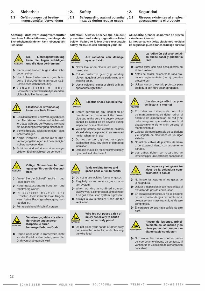
Achtung: Unfallverhütungsvorschriften beachten!Außerachtlassung nachfolgender Sicherheitsmaßnahmen kann lebensgefähr-lich sein!
WARNUNG!
Die Lichtbogenstrahlung kann die Augen schädigen und die Haut verbrennen!
Niemals mit bloßem Auge in den Licht-bogen sehen.Vor Schweißarbeiten vorgeschrie-bene Schutzkleidung anlegen (z.B. Schweißschutzhandschuhe).S c h w e i ß e r h e l m o d e r Schweißer-Schutzschild mit passendem Lichtschutzfilterbenutzen.
GEFAHR!
Elektrischer Stromschlag kann zum Tode führen!
Bei allen Kontroll- und Wartungsarbeiten den Netzstecker ziehen und sicherstel-len, dass während der Wartung niemand die Spannungsversorgung einschaltet!Schweißpistole, Elektrodenhalter stets isoliert ablegen.Keine Pistolen-, Massekabel oder Versorgungsleitungen mit beschädigter Isolierung verwenden.Schäden sind sofort von einer ausge-bildeten Elektrofachkraft zu beheben!
WARNUNG!
Giftige Schweißrauche und -gase gefährden die Gesund-heit!
Atmen Sie die Schweißrauche und -gase nicht ein.Rauchgasabsaugung benutzen und regelmäßig warten.I n b e e n g t e n R ä u m e n e i n e Pressluft-Atemschutzmaske tragen, wenn keine Rauchgasabsaugung vor-handen ist.Für ausreichend Frischluft sorgen.
WARNUNG!
Verletzungsgefahr vor allem der Hände und anderer Körperteile durch herausgeförderten Draht!
Hände oder andere Körperteile nicht vor die Kontaktspitze halten, wenn der Drahtvorschub geprüft wird!
S C H W E I S S E N W E L D I N G W E L D I N GS O L D A D U R A S C H W E I S S E N
12
::
::
2. Seguridad2.3 Riesgos existentes al emplear adecuadamente el producto
ADVERTENCIA!
Peligro de lesiones en los ojos debido al desprendi-miento de virutas, a la abrasi-ón de electrodos de cable y a salpicaduras de soldadura al limpiar interface de giro con aire comprimido!
Utilice siempre gafas protectoras o una visera.
ADVERTENCIA!
Peligro de incendio por formación de chispas!
No soldar cerca de materiales o líquidos inflamables.Mantener alejados del área de trabajo recipientesconlíquidosinflamables.Si se forman llamas, por ejemplo debido a chispas o partes candentes, deben extinguirse.Se debe controlar permanentemente que no se formen focos de incendio en el área de trabajo.Se debe asegurar de que se dispone de suficientesextintoresdeincendio.
PELIGRO!
Peligro de explosión por formación de chispas!
No soldar cerca de materiales o líquidos explosivos.Mantener alejados del área de trabajo recipientes con líquidos explosivos.Si se forman llamas, por ejemplo debido a chispas o partes candentes, deben extinguirse.
ADVERTENCIA!
Peligro por daños auditivos mediante ruido con alto nivel de presión sonora!
Utilice siempre un protector de oídos.
ADVERTENCIA
Peligro de quemaduras severas y de incendio por cabezal caliente!
Después de soldar, nunca tome el cabe-zal con las manos descubiertas.Deje enfriar bien la pistola de soldar, si desea cambiar piezas de desgaste del cabezal.
2. Safety2.3 Safeguarding against potential hazards during regular usage
WARNING!
Eye injury may occur due to flying chips, wire electrode abrasion and weld spatters produced during blow-out of the rotary interface by means of compressed air!
Always wear safety goggles or a visor.
WARNING!
Danger of fire from sparks!
Neverweld near flammablematerialsor liquids.Remove containers with combustible and explosive liquids from the work area.Avoid any formation of flames, e.g. through sparks or glowing parts.Always ensure that there are no sources offireintheworkarea.Alwayskeepasufficientnumberoffireextinguishers available for emergencies.
DANGER!
Danger of explosion from sparks!
Never weld near explosive materials or liquids.Remove containers with explosive liquids from the work area.Avoid any formation of flames, e.g. through sparks or glowing parts.
WARNING!
Danger of hearing loss by excessive noise and sound-pressure levels!
Always wear hearing protection.
WARNING!
Risk of serious burns and/or fire from hot torch head!
Never touch the torch head with bare hands after welding.Allow the welding torch to cool properly if you want to replace wear parts of the torch head.
2. Sicherheit
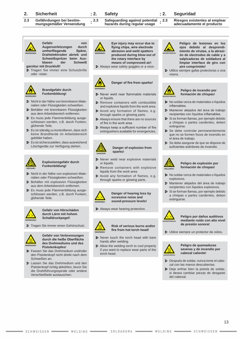
WARNUNG!
Gefahr von Augenverletzungen durch umherfliegende Späne, Drahtelektroden abrieb und Schweißspritzer beim Aus-blasen der Schweiß
garnitur mit Druckluft!Tragen Sie immer eine Schutzbrille oder -visier.
WARNUNG!
Brandgefahr durch Funkenbildung!
Nicht in der Nähe von brennbaren Mate-rialien oder Flüssigkeiten schweißen.Behälter mit brennbaren Flüssigkeiten aus dem Arbeitsbereich entfernen.Es muss jede Flammenbildung ausge-schlossen werden, z.B. durch Funken, glühende Teile.Es ist ständig zu kontrollieren, dass sich keine Brandherde im Arbeitsbereich gebildet haben.Es ist sicherzustellen, dass ausreichend Löschgeräte zur Verfügung stehen.
GEFAHR!
Explosionsgefahr durch Funkenbildung!
Nicht in der Nähe von explosiven Mate-rialien oder Flüssigkeiten schweißen.Behälter mit explosiven Flüssigkeiten aus dem Arbeitsbereich entfernen.Es muss jede Flammenbildung ausge-schlossen werden, z.B. durch Funken, glühende Teile.
WARNUNG!
Gefahr von Hörschäden durch Lärm mit hohem Schalldruckpegel!
Tragen Sie immer einen Gehörschutz.
WARNUNG!
Gefahr von Verbrennungen durch die heiße Oberfläche des Drehmediums und des Pistolenkopfes!
Fassen Sie das Drehmedium und/oder den Pistolenkopf nicht direkt nach dem Schweißen an.Lassen Sie das Drehmedium und den Pistolenkopf richtig abkühlen, bevor Sie die Drahtführungsspirale oder andere Verschleißteile austauschen.
2.3 Gefährdungen bei bestim- mungsgemäßer Verwendung
S C H W E I S S E N W E L D I N G W E L D I N GS O L D A D U R A S C H W E I S S E N
13
: :: :

2. Seguridad2.4 Operarios autorizados
Interface de giro debe ser operado sólo por per-erface de giro debe ser operado sólo por per- debe ser operado sólo por per-sonas capacitadas por DINSE o por un repre-sentante autorizado y que estén familiarizadas con las normas de seguridad correspondientes!
2.5 Derecho de garantía
INFO
La responsabilidad sobre el produc-to y la garantía caducan en caso de operación no autorizada!
La idoneidad interface de giro para un caso dado de aplicación debe ser determinada por el usuario y no está sujeta a la responsabilidad sobre el producto por parte del fabricante.
Para información más detallada sobre la garantía, lea las condiciones generales de entrega de DINSE en www.dinse.eu (U.S. mercado = www.dinse-us.com)
El derecho de garantía sólo es válido en caso de:
● Empleo adecuado
● Funcionamiento adecuado
● Empleo de componentes y piezas de repu-estos originales de DINSE
● Observación de las indicaciones de segu-ridad
Observe que los arreglos deben ser realizados por DINSE o por sus electricistas!
En caso de reclamaciones básicas durante el plazo de garantía, se debe enviar a DINSE interface de giro inalterado.
2. Safety2.4 Authorized operators
The rotary interface must be installed and ope-rated only by persons who have been trained by DINSE and/or an authorized representative and who are aware of the relevant safety instructions.
2.5 Limited Warranty
INFO
U n a u t h o r i z e d t a m p e r i n g , modifications, repairs, or changes to the DINSE product will result in lack of warranty coverage and will void any warranty claims, im-plied or otherwise, as well as any suitability or fitness for particu-lar purposes claims by DINSE!
Seller guarantees Goods meet applicable standards only when used as directed under normal operation or service.
Please refer to the complete warranty claim at www.dinse.eu (U.S. market = www.dinse-us.com) for further details and exceptions of the war-ranty.
Warranty claims can only be asserted given:
● Use for the intended purposes
● Proper operation
● Use of original components and spare parts from DINSE
● Observance of safety instructions
In the event your DINSE product needs repair, any repairs must be performed by either DINSE electriciansorqualifiedelectriciansappointedby DINSE!
If you have a complaint about your DINSE product during the valid warranty term, do NOT makeanymodificationstotheproduct.Pleasesend the product “as-is” to DINSE immediately.
2. Sicherheit2.4 Zugelassene Bediener
Das Drehmedium darf nur von Personen montiert und bedient werden, die durch DINSE und/oder eine autorisierte Vertretung geschult wurden und mit den einschlägigen Sicherheitsvorschriften vertraut sind!
2.5 Gewährleistungsanspruch
INFO
Produkthaftung und Gewährleistung erlöschen bei unbefugten Eingriffen!
Die Eignung des Drehmediums für den jewei-ligen Anwendungsfall muss vom Anwender bestimmt werden und unterliegt nicht der Produkthaftung durch den Hersteller.
Für näherere Informationen zur Gewähr-leistung lesen Sie bit te die al lgemei-nen Lieferbedingungen von DINSE auf www.dinse-eu.com.
Der Gewährleistungsanspruch kann nur geltend gemacht werden bei:
● Bestimmungsgemäßer Verwendung
● Ordnungsgemäßem Betrieb
● Verwendung von Original DINSE Kompo-nenten und Ersatzteilen
● Beachtung der Sicherheitshinweise
Beachten Sie bitte, dass Reparaturen gene-rell nur von DINSE oder von ihr beauftragten Elektrofachkräften ausgeführt werden dürfen!
Bei grundlegenden Beanstandungen während der Gewährleistungszeit ist das Drehmedium unverändert an DINSE zu senden.
S C H W E I S S E N W E L D I N G W E L D I N GS O L D A D U R A S C H W E I S S E N
14
::
::
2. Seguridad2.6 Transporte y embalaje
Eljuegoparasoldaduraseverificayembalacuidadosamente antes del envío. No obstante, no se descartan daños durante el transporte.
En caso de mal funcionamiento, póngase en contacto con DINSE – Distribuidores a su país, y envíe el juego para soldar completo a:
Para evitar daños durante el envío, interface de girodebeestarlosuficientementeprotegido!
Añadir indicaciones acerca del fallo en cuestión facilita a nuestro departamento la investigación de sus causas y puede acortar considerable-mente el tiempo de reparación.
2.7 Reciclaje/Eliminación de basura
2.7.1 Países de la UE
No tire las herramientas eléctricas en la basura doméstica!
Conforme a la directiva europea 2002/96/CE sobre residuos de aparatos eléctricos y elec-trónicos y su aplicación de acuerdo con la le-gislación nacional, las herramientas eléctricas cuyavidaútilhayallegadoasufinsedeberánrecoger por separado y trasladar a una planta de reciclaje que cumpla con las exigencias ecológicas.
2.7.2 En otros paísesAlgunos de los materiales del sistema tándem pueden ser reutilizados. Al reutilizar algunas partes o al producir materia prima de produc-tos usados, realiza un importante aporte a la protección del medio ambiente.Comuníquese con sus autoridades locales en caso de necesitar información sobre los puntos de recolección en su zona.
2. Safety2.6 Transportation and packaging
The rotary interface has been checked and carefully packed before shipment, however damages may occur during shipping and this product should be carefully inspected prior to use.
In case of damage, contact the DINSE – Distri-butor of your country immediately and return the entire rotary interface at your expense to:
IN THE EVENT YOUR DINSE ROTARY INTERFACE NEEDS TO BE RETURNED:1. Please be sure to carefully pack the rotary
interface in a suitable container with suf-ficient packingmaterial in order to avoidcausing any damages during shipping.
2. Please include a note describing the problem(s)withsufficientdetail. Thiswillhelp our service department to determine the cause of the problem sooner, and can reduce the time it takes to repair the rotary interface.
2.7 Recycling / Disposal
2.7.1 EU countriesDo not discard electrical appliances with ordinary waste!
As per EU directive 2002/96/EC regarding old electrical and electronic appliances and as implemented in national law, used electrical appliances must be collected separately and recycled in an eco-friendly manner.
2.7.2 Other countriesSome of the rotary interface’s materials can be reused. Reusing some parts of raw materials from used products is an important way of helping to protect the environment.Contact your local authority in the event that you require information on local collection points.
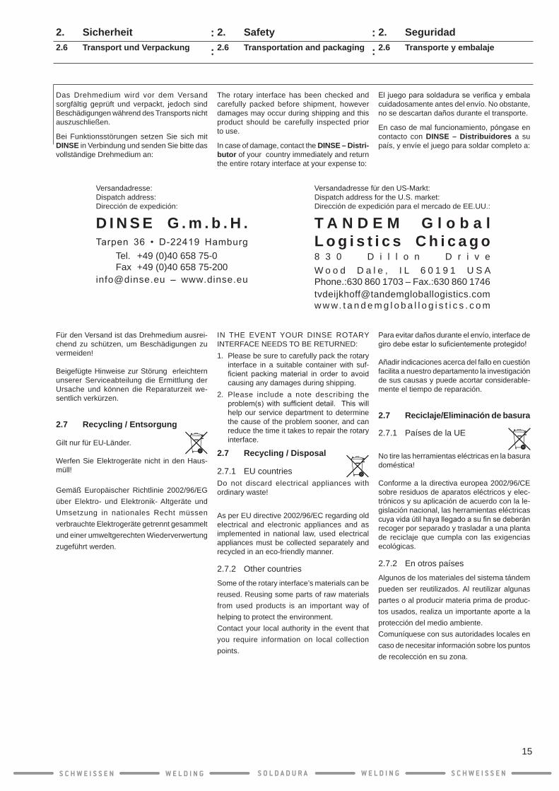
2. Sicherheit2.6 Transport und Verpackung
Das Drehmedium wird vor dem Versand sorgfältig geprüft und verpackt, jedoch sind Beschädigungen während des Transports nicht auszuschließen.
Bei Funktionsstörungen setzen Sie sich mit DINSE in Verbindung und senden Sie bitte das vollständige Drehmedium an:
Für den Versand ist das Drehmedium ausrei-chend zu schützen, um Beschädigungen zu vermeiden!
Beigefügte Hinweise zur Störung erleichtern unserer Serviceabteilung die Ermittlung der Ursache und können die Reparaturzeit we-sentlich verkürzen.
2.7 Recycling / Entsorgung
Gilt nur für EU-Länder.
Werfen Sie Elektrogeräte nicht in den Haus-müll!
Gemäß Europäischer Richtlinie 2002/96/EG über Elektro- und Elektronik- Altgeräte und Umsetzung in nationales Recht müssen verbrauchte Elektrogeräte getrennt gesammelt und einer umweltgerechten Wiederverwertung zugeführt werden.
D I N S E G . m . b . H .Tarpen 36 • D-22419 Hamburg
Tel. +49 (0)40 658 75-0Fax +49 (0)40 658 75-200
[email protected] – www.dinse.eu
T A N D E M G l o b a lL o g i s t i c s C h i c a g o8 3 0 D i l l o n D r i v e
[email protected] w w. t a n d e m g l o b a l l o g i s t i c s . c o m
W o o d D a l e , I L 6 0 1 9 1 U S APhone.:630 860 1703 – Fax.:630 860 1746
Versandadresse:Dispatch address:Dirección de expedición:
Versandadresse für den US-Markt:Dispatch address for the U.S. market:Dirección de expedición para el mercado de EE.UU.:
S C H W E I S S E N W E L D I N G W E L D I N GS O L D A D U R A S C H W E I S S E N
15
: :: :

3. Datos técnicos3. Technical Data3. Technische Daten
S C H W E I S S E N W E L D I N G W E L D I N GS O L D A D U R A S C H W E I S S E N
16
Schweißverfahren MIG/MAG-Schweißen und LötenWelding technique MIG/MAG welding and solderingProcedimientos de soldadura Soldadura y uniones por soldadura MIG/MAG
SchutzartIP 23Protection class
Tipo de protección
Drehbarkeit 260° im Uhrzeigersinn - 260° gegen den UhrzeigersinnRotation 260° clockwise - 260° anti-clockwiseRotabilidad 260° sentido horario - 260° anti-sentido horario
Auslenkung(Crash-Schutz,nurflexibleAusführung)
15°Deflection (crash-protection, only flexible version)Deflección(protecciónanticolisión,diseñoflexible)
Abmessungen
94 mm x 154 mmDimensions (ø x L)Dimensiones
Gewicht ca.1.4 kgWeight approx.
Peso aprox.
Umgebungstemperatur – im Betrieb-10 °C – +40 °C / 14 °F – +104 °FAmbient temperature – during operation
Temperatura ambiental – en funcionamiento
Umgebungstemperatur – bei Transport und Lagerung-10 °C – +55 °C / 14 °F – +131 °FAmbient temperature – during transportation and storage
Temperatura ambiental – durante el transporte y almacenamiento
DIX Bezeichnung / DIX designation / DIX denominación
DIX RET 341 FDIX RET 341 S
FlexibleSteep
DIX RET 341 F/WB 1 Flexible/Wire Brake
DIX RET 341 S/WB 1 Steep/Wire Brake
WB 1 ø 0.8 - 1.6mm
: :
4. Instrucciones de uso
Existe una gran variedad de tipos de robot y de fabricantes de sistemas de robot. Por motivos de espacio, el montaje se representa con un robotficticio,yaquelospasosdetrabajosonprácticamente iguales. Para ver detalles espe-ciales de algunos tipos de robot, consulte por favor los anexos.
Los detalles de los diferentes variantes de sistema, como por ejemplo el modelo del enchufe compacto, la longitud del cable de alimentación, el equipamiento del cabezal de la pistola, las piezas de reemplazo y de desgaste, los puede tomar de las correspon-dientes listas actuales de piezas de reemplazo y de desgaste.
Las distintas tareas de soldadura que surgen en la práctica se llevan a cabo mediante diferentes modelos del cabezal de pistola con toberas de gas, puntas de contacto y zócalos especiales.
Así, en caso de que se tenga que realizar una tarea de soldadura con una baja inten-sidad de corriente (arco voltaico corto), se utiliza normalmente una tobera de gas con un diámetro interno menor y un zócalo de punto de contacto largo.
En cambio, los trabajos de soldadura de alto rendimiento (arco voltaico de chispas) gene-ralmente deben ejecutarse con un zócalo y una tobera de gas con diámetro interno mayor.
Para soldar aluminio se deben emplear rodillos de accionamiento con ranuras especialmente moldeadas en el sistema de alimentación del cable. Si se utilizan electrodos de cable de aluminio y cromo-níquel, se recomienda un capilar de guía de hilo, en vez de una espiral de guía de hilo.
Interfaz de giro con freno del hilo integradoUna interfaz de giro con freno del hilo integrado es ideal para aplicaciones con sensor táctil.Elfrenodelhilogarantizauncálculofiabledela localización del cordón de soldadura.El freno del hilo integrado mantiene, por medio de ciclos de frenado programables, el hilo siempre en la misma posición exacta. El TCP se mantiene estable durante todo el proceso de medida. El freno del hilo integrado garantiza un Stickout totalmente constante, incluso con diferentes diámetros del hilo.
4. Instructions for use
There are many different robot types and numerous robot manufacturers. Due to space limitations the assembly of a fictitious robotis shown, since the work steps do not differ significantly.Pleaserefertotheappendicesforspecial features of some robot types.
Please review the lists below for current details on the particular variations for your system, for example: compact-plug design, supply-line length, torch-head assembly, spare parts and wearing parts.
Various welding applications required in prac-tice are covered by different designs of pistol head including special gas nozzles, contact tips and tip adapters.
For welding with low voltages (short arc weld-ing) in constrained positions, a gas nozzle with a small inner diameter and a long contact-tip adapter should be used.
However, any welding operations at high power (spray arc) should be performed with a gas nozzle of a large inner diameter and a short tip adapter.
For aluminum welding, you must use drive roll-ers with specially formed grooves in the wire feed system.
We recommend the use of a capillary liner with wire electrodes made of aluminium and chromium-nickel.We do not recommend the use of a liner for this purpose.
Rotary interfaces with integrated wire brake
Rotary interfaces with integrated wire brake are perfect for using with tactile sensors. The wire brake assures a secure calculation of the position of the welding line.The wire brake is freely programmable and keeps the wire in the same position exactly. The TCP will be maintained throughout the whole measurement process.The wire brake assures a constant stickout even with different wire diameters.
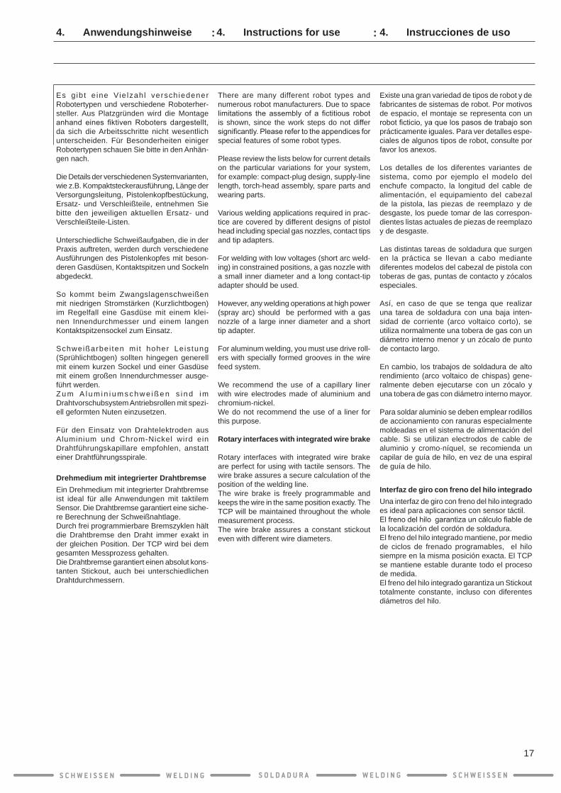
Es g ib t e ine Vie lzahl versch iedener Robotertypen und verschiedene Roboterher-steller. Aus Platzgründen wird die Montage anhand eines fiktivenRoboters dargestellt,da sich die Arbeitsschritte nicht wesentlich unterscheiden. Für Besonderheiten einiger Robotertypen schauen Sie bitte in den Anhän-gen nach.
Die Details der verschiedenen Systemvarianten, wie z.B. Kompaktsteckerausführung, Länge der Versorgungsleitung, Pistolenkopfbestückung, Ersatz- und Verschleißteile, entnehmen Sie bitte den jeweiligen aktuellen Ersatz- und Verschleißteile-Listen.
Unterschiedliche Schweißaufgaben, die in der Praxis auftreten, werden durch verschiedene Ausführungen des Pistolenkopfes mit beson-deren Gasdüsen, Kontaktspitzen und Sockeln abgedeckt.
So kommt beim Zwangslagenschweißen mit niedrigen Stromstärken (Kurzlichtbogen) im Regelfall eine Gasdüse mit einem klei-nen Innendurchmesser und einem langen Kontaktspitzensockel zum Einsatz.
Schweißarbei ten mi t hoher Leis tung (Sprühlichtbogen) sollten hingegen generell mit einem kurzen Sockel und einer Gasdüse mit einem großen Innendurchmesser ausge-führt werden. Z u m A l u m i n i u m s c h w e i ß e n s i n d i m Drahtvorschubsystem Antriebsrollen mit spezi-ell geformten Nuten einzusetzen.
Für den Einsatz von Drahtelektroden aus Aluminium und Chrom-Nickel wird ein Drahtführungskapillare empfohlen, anstatt einer Drahtführungsspirale.
Drehmedium mit integrierter DrahtbremseEin Drehmedium mit integrierter Drahtbremse ist ideal für alle Anwendungen mit taktilem Sensor. Die Drahtbremse garantiert eine siche-re Berechnung der Schweißnahtlage. Durch frei programmierbare Bremszyklen hält die Drahtbremse den Draht immer exakt in der gleichen Position. Der TCP wird bei dem gesamten Messprozess gehalten. Die Drahtbremse garantiert einen absolut kons-tanten Stickout, auch bei unterschiedlichen Drahtdurchmessern.
4. Anwendungshinweise
S C H W E I S S E N W E L D I N G W E L D I N GS O L D A D U R A S C H W E I S S E N
17
: :

5. Puesta en marcha5.1 Montaje en el brazo del robot
5.1.1 Herramientas y componentes
INFO
Emplee solo herramientas sin grasa y sin desgaste.
En el lugar de montaje se aplican las normas de prevención de accidentes.La conexión eléctrica sólo la podrá realizar un electricista cualificado.
Para montar la pistola necesitará las siguientes herramientas:
● Llave de hexágono interior SW 3 /SW 4 /SW 5
● Llave de tornillos SW 8
● Alicates de corte diagonal
● Llave para tuercas ranuradas DIX SLAT 4
En función de la punta de contacto seleccio-nada:
● Llave especial DIX SSL 1/2
● Llave de enchufe DIX SSLA 1 / DIX SSLA 2 / DIX STLA 3 M8
● Llave de enchufe DIX SCS 300
INFO
Encontrará más información sobre las herramientas de DINSE en el catálogo de productos de DINSE.
Prepare los siguientes componentes para el montaje:
● Brida de adaptación DIX ADFRD 63xx (tipo en función del robot)
● Interfaz rotativa DIX RET 341 x/xx x
● Pistola DIX RET 320 - xx
● Tubuladora DIX MES 300/500
● Espiral de guía de hilo o capilar de guía de hilo
● Cabezal de pistola (por ejemplo, DIX METR 35x)
● Conexión de medios DIX REMA 1xx
● Pinza de contacto DIX K 180 ME (para sensor de tobera de gas)
INFO
Para determinar la brida de adaptación adecuada, consulte por favor la lista de bridas de adaptación del catálogo de productos.
5. Installation5.1 Mounting on a robot arm
5.1.1 Tools and components
INFO
Use only tools that are free from grease and not worn.
The respective accident prevention regulations apply at the assembly site.The electrical connection may be made only by a trained electrician.
You will need the following tools for the assem-bly of the torch set:
● Hexagon key 3 mm/ 4 mm/ 5 mm
● Wrench 8 mm
● Wire cutter
● Hook spanner DIX SLAT 4
Depending on the contact tip chosen:
● Special wrench DIX SSL 1/2
● Socket spanner DIX SSLA 1 / DIX SSLA 2 / DIX STLA 3 M8
● Socket spanner DIX SCS 300
INFO
Refer to the DINSE product catalog for more details about DINSE tools.
Have the following components ready for assembly:
● AdapterflangeDIXADFRD63xx (type depending on robot)
● Rotary interface DIX RET 341 x/xx x
● Torch set DIX RET 320- xx
● Connecting piece DIX MES 300/500
● Liner or capillary liner
● Torch head (e.g. DIX METR 35x)
● Media connection DIX REMA 1xx
● Contact clamp DIX K 180 ME (for gas nozzle sensor)
INFO
Please refer to the adapter flange list in the product catalog to determine the appropriate adapter flange.
5. Inbetriebnahme5.1 Montage am Roboterarm
5.1.1 Werkzeuge und Bauteile
INFO
Benutzen Sie nur Werkzeuge, die fett-frei und nicht abgenutzt sind.
Am Montageort gelten die entsprechenden Unfallverhütungsvorschriften.Der elektrische Anschluss darf nur von einer ausgebildeten Elektrofachkraft vorgenommen werden.
Folgende Werkzeuge benötigen Sie zur Mon-tage der Schweißgarnitur:
● Innensechskantschlüssel SW 3 /SW 4 /SW 5
● Schraubenschlüssel SW 8
● Seitenschneider
● Hakenschlüssel DIX SLAT 4
Je nach ausgewählter Kontaktspitze:
● Spezialschlüssel DIX SSL 1/2
● Steckschlüssel DIX SSLA 1 / DIX SSLA 2 / DIX STLA 3 M8
● Steckschlüssel DIX SCS 300
INFO
N ä h e r e I n f o r m a t i o n e n z u DINSE-Werkzeugen finden Sie im DINSE-Produktkatalog.
Legen Sie folgende Bauteile für die Montage bereit:
● AdapterflanschDIXADFRD63xx (Typ abhängig vom Roboter)
● Drehmedium DIX RET 341 x/xx x
● Schweißgarnitur DIX RET 320- xx
● Stutzen DIX MES 300/500
● Drahtführungsspirale bzw. -kapillare
● Pistolenkopf (z.B. DIX METR 35x)
● Medien-Anschluss DIX REMA 1xx
● Kontaktklemme DIX K 180 ME (für Gasdüsensensor)
INFO
Zur Bestimmung des passenden Adapterflansches sehen Sie bitte in die Adapterflanschliste im Produktkatalog..
S C H W E I S S E N W E L D I N G W E L D I N GS O L D A D U R A S C H W E I S S E N
18
::
:
::
:

5. Puesta en marcha5.1 Montaje en el brazo del robot
5.1.2 Montaje de la brida de adaptación
INFO
¡Por favor tenga siempre en cuenta las indicaciones de montaje de los robots Fanuc con Solution Arm del anexo J!
1. Antesdefijar la interfaz rotativa,el robotdebe colocarse en el punto de referencia para facilitar el montaje de la interfaz rotativa.
INFO
En función del tipo de robot, el pin de posición tendrá una determinada posi-ción. En este caso, el pin de posición está abajo si se ha ajustado el punto de referencia.
2. Limpie y elimine a fondo la grasa de la brida del brazo del robot.
INFO
¡Por favor tenga siempre en cuenta las indicaciones de montaje de los robots ABB con brida adicional de adaptación del anexo B!
3. Coloque la brida de adaptación sobre la brida del brazo del robot. Alinee la brida de adaptación en el pin de posición.
INFO
P l e a s e n o t e t h e a s s e m b l y instructions for Fanuc robots with Solution Arm in Appendix J!
1. Before mounting the rotary interface the robot must be set to the reference point to make assembly of the rotary interface easier.
INFO
The position pin is in a specific position depending on the robot type. In this case, the position pin is down when the reference point is set.
2. Thoroughlycleananddegreasetheflangeof the robot arm.
INFO
P l e a s e n o t e t h e a s s e m b l y instruct ions for ABB robots with additional adapter flange in Appendix B!
3. Place theadapterflangeon theflangeoftherobotarm.Aligntheadapterflangeonthe position pin at the same time.
5. Installation5.1 Mounting on a robot arm
5.1.2 Mountingoftheadapterflange
INFO
B e a c h t e n S i e b i t t e d i e Montagehinweise für Fanuc-Roboter mit Solution Arm im Anhang J!
1. Vor der Befestigung des Drehmediums muss der Roboter auf den Referenzpunkt gestellt werden, um die Montage des Drehmediums zu erleichtern.
INFO
Je nach Robotertyp nimmt der Posi- tionspin eine individuelle Position ein. In diesem Fall ist der Positionspin unten, wenn der Referenzpunkt eingestellt ist.
2. Reinigen und entfetten Sie gründlich den Flansch des Roboterarms.
INFO
B e a c h t e n S i e b i t t e d i e Montagehinweise für ABB-Roboter mit zusätzlichem Adapterflansch im Anhang B!
3. Setzen Sie den Adapterflansch auf den Flansch des Roboterarms. Richten Sie da-beidenAdapterflanschamPositionspinaus.
5. Inbetriebnahme5.1 Montage am Roboterarm
5.1.2 MontagedesAdapterflansches
S C H W E I S S E N W E L D I N G W E L D I N GS O L D A D U R A S C H W E I S S E N
19
::
:
::
:
PositionspinPosition pinPin de posición
5. Puesta en marcha5.1 Montaje en el brazo del robot
5.1.2 Montaje de la brida de adaptación
¡ATENCIÓN!
Las cabezas que sobresal-gan de los tornillos de hexá-gono interior y/o el pin de posición podrían provocar una descarga eléctrica a tra-vés de la brida de adaptación en el robot.
Asegúrese de que los tornillos de hexágono interior no sobresalgan de su asiento.
1. Atornille la brida de adaptación con una lla-ve de hexágono interior SW 3 y los tornillos de hexágono interior suministrados, con un par de 3 Nm.
5.1.3 Montaje del devanador de hilo
Monte el devanador de hilo con ayuda del kit de placas de montaje que se suministra opcionalmente.
INFO
Se recomienda montar el devanador de hilo delante de la pistola. Se debe montar primero la pistola en el devana-dor de hilo si ésta se coloca muy cerca en el brazo del robot. Si el devanador de hilo se encuentra en su posición de trabajo, ya no tendrá acceso a la conexión del devanador de hilo.
INFO
A petición se puede fabricar y sumi-nistrar un kit de placas de montaje a la medida de su tipo de robot.
CAUTION!
Protruding heads of the hexagon socket screws and/or the position pin will cause an electrical short circuit through the adapter flange on the robot.
Make sure that the hexagon socket screws and the position pin do not pro-trude beyond the countersink.
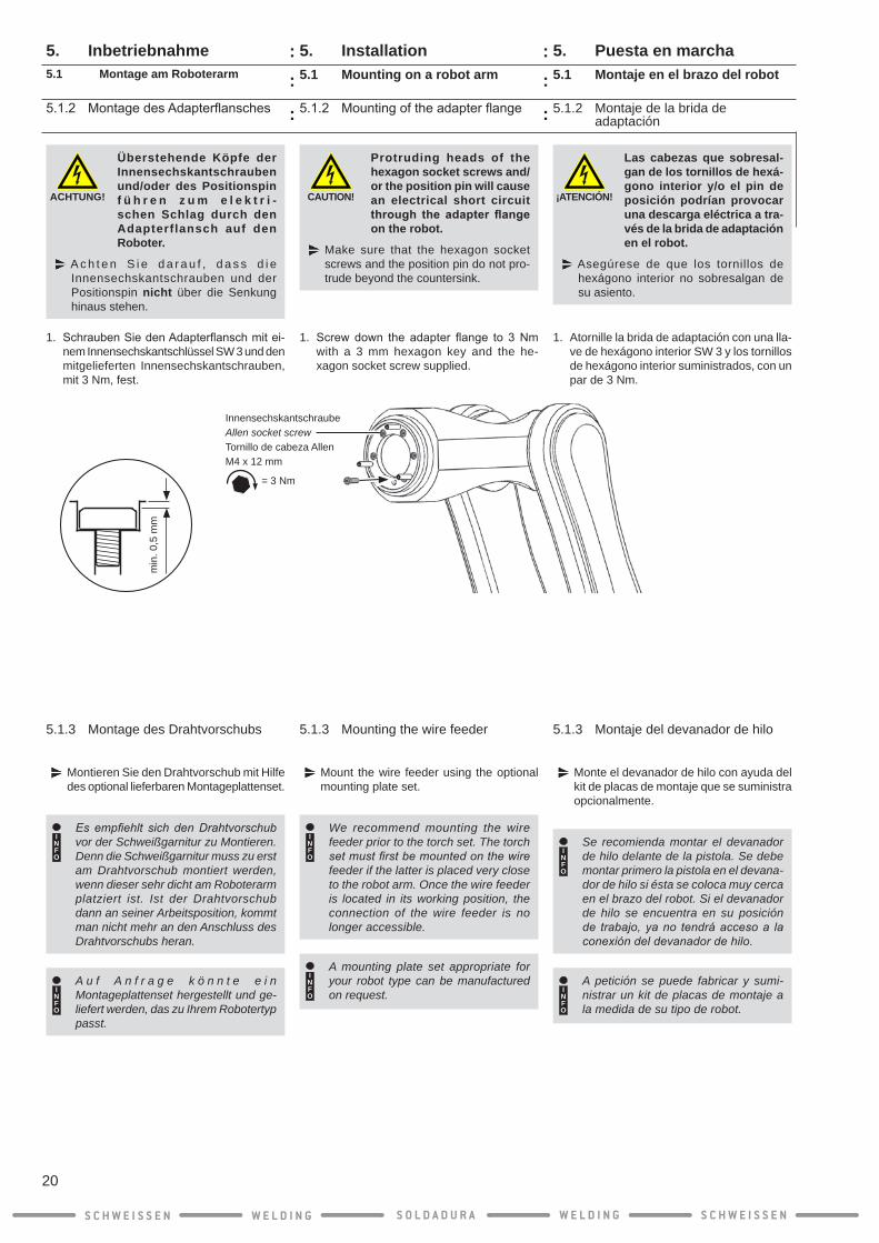
1. Screwdown the adapter flange to 3Nmwith a 3 mm hexagon key and the he-xagon socket screw supplied.
5.1.3 Mounting the wire feeder
Mount the wire feeder using the optional mounting plate set.
INFO
We recommend mounting the wire feeder prior to the torch set. The torch set must first be mounted on the wire feeder if the latter is placed very close to the robot arm. Once the wire feeder is located in its working position, the connection of the wire feeder is no longer accessible.
INFO
A mounting plate set appropriate for your robot type can be manufactured on request.
5. Installation5.1 Mounting on a robot arm
5.1.2 Mountingoftheadapterflange
ACHTUNG!
Überstehende Köpfe der Innensechskantschrauben und/oder des Positionspin f ü h r e n z u m e l e k t r i -schen Schlag durch den Adapterflansch auf den Roboter.
A c h t e n S i e d a r a u f , d a s s d i e Innensechskantschrauben und der Positionspin nicht über die Senkung hinaus stehen.
1. SchraubenSiedenAdapterflanschmitei-nem Innensechskantschlüssel SW 3 und den mitgelieferten Innensechskantschrauben, mit 3 Nm, fest.
5.1.3 Montage des Drahtvorschubs
Montieren Sie den Drahtvorschub mit Hilfe des optional lieferbaren Montageplattenset.
INFO
Es empfiehlt sich den Drahtvorschub vor der Schweißgarnitur zu Montieren. Denn die Schweißgarnitur muss zu erst am Drahtvorschub montiert werden, wenn dieser sehr dicht am Roboterarm platziert ist. Ist der Drahtvorschub dann an seiner Arbeitsposition, kommt man nicht mehr an den Anschluss des Drahtvorschubs heran.
INFO
A u f A n f r a g e k ö n n t e e i n Montageplattenset hergestellt und ge-liefert werden, das zu Ihrem Robotertyp passt.
5. Inbetriebnahme5.1 Montage am Roboterarm
5.1.2 MontagedesAdapterflansches
S C H W E I S S E N W E L D I N G W E L D I N GS O L D A D U R A S C H W E I S S E N
20
::
:
::
:
InnensechskantschraubeAllen socket screwTornillo de cabeza AllenM4 x 12 mm
= 3 Nm
min
. 0,5
mm

¡ATENCIÓN!
¡Con la interfaz rotativa DIX RET 341 F(S)/WB 1 o 2, tenga en cuenta las indicaciones de montaje de la “interfaz rotativa con freno de hilo“ en el anexo E!
1. Si el devanador de hilo está demasiado cerca del brazo del robot, coloque el deva-nador de hilo en una posición que tenga libre acceso a todas las conexiones.
2. Abra la cubierta del devanador de hilo.
3. Suelte el tornillo de hexágono interior de la pieza de sujeción con una llave de hexá-gono interior SW 5.
4. Inserte la pistola por el cuarto eje del brazo del robot e introduzca el perno de conexión hasta el tope en la conexión de medios DIX REMA 100.
5. Puesta en marcha5.1 Montaje en el brazo del robot
5.1.4 Montaje de la pistola de soldadura en el devanador de hilo
CAUTION!
With the DIX RET 341 F(S)/WB 1 or 2 rotary interface please observe the moun-ting notes for the “Rotary interface with wire brake” in Appendix E !
1. If the wire feeder is located very close to the robot arm, move it to a position where you have free access to all connections.
2. Open the cover of the wire feeder.
3. Loosen the hexagon socket screw of the clamping piece with a 5 mm hexagon key.
4. Guide the torch set through the 4th axis of the robot arm and insert the connecting mandrel against the stop into the DIX REMA 100 media connection.
5. Installation5.1 Mounting on a robot arm
5.1.4 Mounting the torch set on the wire feeder
5. Inbetriebnahme5.1 Montage am Roboterarm
5.1.4 Montage der Schweißgarnitur am Drahtvorschub
ACHTUNG!
Beachten Sie bi t te bei d e m D r e h m e d i u m D I X RET 341 F(S)/WB 1 oder 2 die Montagehinweise für das “Drehmedium mit Drahtbremse“ im Anhang E !
1. Wenn der Drahtvorschub sehr dicht am Roboterarm sitzt, bringen Sie den Drahtvorschub in eine Position in der sie freien Zugang zu allen Anschlüssen haben.
2. Öffnen Sie den Deckel des Drahtvorschubs.
3. Lösen Sie die Innensechskantschraube d e s K l e m m s t ü c k e s m i t e i n e m Innensechskantschlüssel SW 5.
4. Führen Sie die Schweißgarnitur durch die 4. Achse des Roboterarms und stecken den Anschlussdorn bis zum Anschlag in den Medien-Anschluss DIX REMA 100.
S C H W E I S S E N W E L D I N G W E L D I N GS O L D A D U R A S C H W E I S S E N
21
::
:
::
:
InnensechskantschraubeAllen socket screwTornillo de cabeza AllenM6 x 20 mm
5. Atornille el tornillo de hexágono interior de la pieza de sujeción en el devanador de hilo con la llave de hexágono interior SW 5, con un par de 10 Nm.
6. Cierre la carcasa del devanador de hilo y póngalo, en caso necesario, en su posición de trabajo.
7. Si emplea un sensor de tobera de gas, conecte el cable del sensor de toberas de gas verde.
8. El cable rojo está conectado a la conexión de la pistola (corriente de soldadura +).
5. Puesta en marcha5.1 Montaje en el brazo del robot
5.1.4 Montaje de la pistola en el devanador de hilo
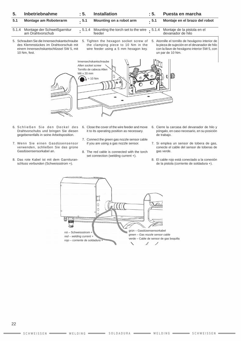
5. Tighten the hexagon socket screw of the clamping piece to 10 Nm in the wire feeder using a 5 mm hexagon key.
6. Close the cover of the wire feeder and move it to its operating position as necessary.
7. Connect the green gas nozzle sensor cable if you are using a gas nozzle sensor.
8. The red cable is connected with the torch set connection (welding current +).
5. Installation5.1 Mounting on a robot arm
5.1.4 Mounting the torch set to the wire feeder
5. Schrauben Sie die Innensechskantschraube des Klemmstückes im Drahtvorschub mit einem Innensechskantschlüssel SW 5, mit 10 Nm, fest.
6. S c h l i e ß e n S i e d e n D e c k e l d e s Drahtvorschubs und bringen Sie diesen gegebenenfalls in seine Arbeitsposition.
7. Wenn S ie e inen Gasdüsensensor verwenden, schließen Sie das grüne Gasdüsensensorkabel an.
8. Das rote Kabel ist mit dem Garnituran-schluss verbunden (Schweissstrom +).
5. Inbetriebnahme5.1 Montage am Roboterarm
5.1.4 Montage der Schweißgarnitur am Drahtvorschub
S C H W E I S S E N W E L D I N G W E L D I N GS O L D A D U R A S C H W E I S S E N
22
::
:
::
:
rot – Schweissstrom + red – welding current + rojo – corriente de soldadura +
InnensechskantschraubeAllen socket screwTornillo de cabeza AllenM6 x 20 mm
= 10 Nm
grün – Gasdüsensensorkabelgreen – Gas nozzle sensor cableverde – Cable de sensor de gas boquilla

5.1.5 Montaje de la pistola en el brazo del robot (sexto eje)
¡ATENCIÓN!
¡Tenga en cuenta las indica-ciones de montaje del robot Motoman-Yaskawa con pro-tección frente a pandeo en el sexto eje del anexo A (1.)!
1. Inserte la pistola por el sexto eje del brazo
del robot hasta que la pieza de conexión ECO sobresalga.
2. Coloque la sujeción de la pistola de solda-dura en la pistola y guíe el cable del sensor detoberasdegastáctilatravésdelorificioprevisto.
5. Puesta en marcha5.1 Montaje en el brazo del robot
CAUTION!
Please observe the mounting notes for Motoman-Yaskawa robots with bend protection on the 6th axis in appendix A (1.)
1. Guide the torch set through the 6th axis
of the robot arm until the ECO connecting piece protrudes.
2. Place the torch set fixture on the torch set, pull the cable for the tactile gas nozzle sensor through the hole provided.
5.1.5 Mounting the torch set on the robot arm (6th axis)
5. Installation5.1 Mounting on a robot arm
5.1.5 Montage der Schweißgarnitur am Roboterarm (6. Achse)
ACHTUNG!
Beachten Sie bi t te die Montagehinweise für Moto-man-Yaskawa-Roboter mit Knickschutz an der 6. Achse im Anhang A (1.)
1. Führen Sie die Schweißgarnitur durch die
6. Achse des Roboterarms, bis das ECO-Anschlußstück herausguckt.
2. Setzen Sie die Schweißgarniturbefestigung auf die Schweißgarnitur, ziehen sie das Kabel für den taktilen Gasdüsensensor durch die vorgesehene Bohrung.
5. Inbetriebnahme5.1 Montage am Roboterarm
S C H W E I S S E N W E L D I N G W E L D I N GS O L D A D U R A S C H W E I S S E N
23
::
:
::
:
GasdüsensensorkabelGas nozzle sensor cableCable de sensor de gas boquilla
ECO-AnschlußstückECO-ConnectionECO-Conexión

5.1.5 Montaje de la pistola en el brazo del robot (sexto eje)
3. Atornille la sujeción de la pistola con los dos tornillos hexagonales suminis-trados (M4 x 12 mm) con una llave de hexágono interior S W 2,5, con 3 Nm.
4. Desplace la pistola con la sujeción hasta el tope de la brida adaptadora en el sexto eje del brazo del robot. Alinee la suje-ción de la pistola en el pin de posición.
5. Atornille la sujeción de la pistola con los dos tornillos de hexágono interior suministrados (M5 x 8 mm) con una llave de hexágono interior SW 4, con un par de 3 Nm.
5. Puesta en marcha5.1 Montaje en el brazo del robot
5.1.5 Mounting the torch set on the robot arm (6th axis)
3. Screwdown the torchsetfixturewith thetwoflatheadscrews(M4x12mm)suppliedto 3 Nm using a 2.5 mm hexagon key.
4. Slidethetorchsetwiththetorchsetfixtureagainstthestopontheadapterflangeintothe6th axis of the robot arm. Align the torch set fixtureonthepositionpinatthesametime.
5. Screwdownthetorchsetfixtureto3Nmwith the two hexagon socket screws (M5 x 8 mm) using a 4 mm hexagon key.
5. Installation5.1 Mounting on a robot arm
5.1.5 Montage der Schweißgarnitur am Roboterarm (6. Achse)
3. Schrauben Sie Schweißgarniturbefestigung mit den zwei mitgel iefer ten Senk-schrauben (M4 x 12 mm) mit einem Innensechskantschlüssel SW 2,5, mit 3 Nm, fest.
4. Schieben Sie die Schweißgarnitur mitsamt der Schweißgarniturbefestigung bis zum Anschlag amAdapterflansch in die 6.Achse vom Roboterarm. Richten Sie dabei die Schweißgarniturbefestigung am Positionspin aus.
5. Schrauben Sie die Schweißgarniturbe-festigung mit den zwei mitgelieferten Innensechskantschrauben (M5 x 8 mm) mit einem Innensechskantschlüssel SW 4, mit 3 Nm, fest.
5. Inbetriebnahme5.1 Montage am Roboterarm
S C H W E I S S E N W E L D I N G W E L D I N GS O L D A D U R A S C H W E I S S E N
24
InnensechskantschraubeAllen socket screwTornillo de cabeza Allen2 x M5 x 8 mm
= 3 Nm
= 3 Nm
Gewindestifte für Sechskantmuttern zur Befestigung des DrehmediumsThread pins for Allen nuts for mounting the rotary mediumPins de rosca para tuercas Allen para el montaje del soporte giratorio
PositionspinPosition pinPin de posición
Senkschraube Countersunk screwTornillo avellanado2 x M4 x 12 mm
::
:
::
:

5.1.6 Montaje de la interfaz rotativa
1. Engrase todas las juntas tóricas de la conexión de la pistola con la vaselina téc-nica suministrada.
¡ATENCIÓN!
¡Con la interfaz rotativa DIX RET 341 F(S)/WB 1 o 2, tenga en cuenta las indicaciones de montaje de la “interfaz rotativa con freno de hilo“ en el anexo E!
2. Guíe el cable de las toberas de gas desde atrásatravésdelorificiolateraldelainterfazrotativa.
5. Puesta en marcha5.1 Montaje en el brazo del robot
1. Grease each individual O-ring of the torch set connection using the technical Vaseline supplied.
CAUTION!
With the DIX RET 341 F(S)/WB 1 or 2 rotary interface please observe the mounting notes for the “Rotary interface with wire brake” in Appendix E !
2. Pull the gas nozzle sensor cable from the rear through the lateral opening of the rotary interface.
5.1.6 Mounting the rotary interface
5. Installation5.1 Mounting on a robot arm
5.1.6 Montage des Drehmediums
1. Fetten Sie jeden einzelnen O-Ring des Schweißgarnituranschlusses ringsum mit der mitgelieferten technischen Vaseline ein.
ACHTUNG!
Beachten Sie bi t te bei d e m D r e h m e d i u m D I X RET 341 F(S)/WB 1 oder 2 die Montagehinweise für das “ Drehmedium mit Drahtbremse“ im Anhang E !
2. Ziehen Sie das Gasdüsensensorkabel von hinten durch die seitliche Öffnung des Drehmediums.
5. Inbetriebnahme5.1 Montage am Roboterarm
S C H W E I S S E N W E L D I N G W E L D I N GS O L D A D U R A S C H W E I S S E N
25
GasdüsensensorkabelGas nozzle sensor cableCable de sensor de gas boquilla
::
:
::
:
¡ATENCIÓN!
En caso de una colocación angulada o inclinada de la interfaz rotativa, las juntas tóricas podrían dañarse en la conexión de la pistola. En este caso, las conexiones de gas no estarán estancas, por lo que es posible que salga agua en la interfaz rotativa de forma incontrolada.
Coloque la interfaz rotatoria con cuidado y de forma recta en la conexión de la pistola.
Nunca desplace la interfaz rotativa con excesiva fuerza en la conexión de la pistola.
3. Coloque la interfaz rotativa en posición recta en la pistola y desplácela con cuidado hasta el tope de la sujeción de la pistola.
4. Atornille las tuercas hexagonales y las tres arandelas con la mano en los tornillos prisioneros.
5.1.6 Montaje de la interfaz rotativa
5. Puesta en marcha5.1 Montaje en el brazo del robot
CAUTION!
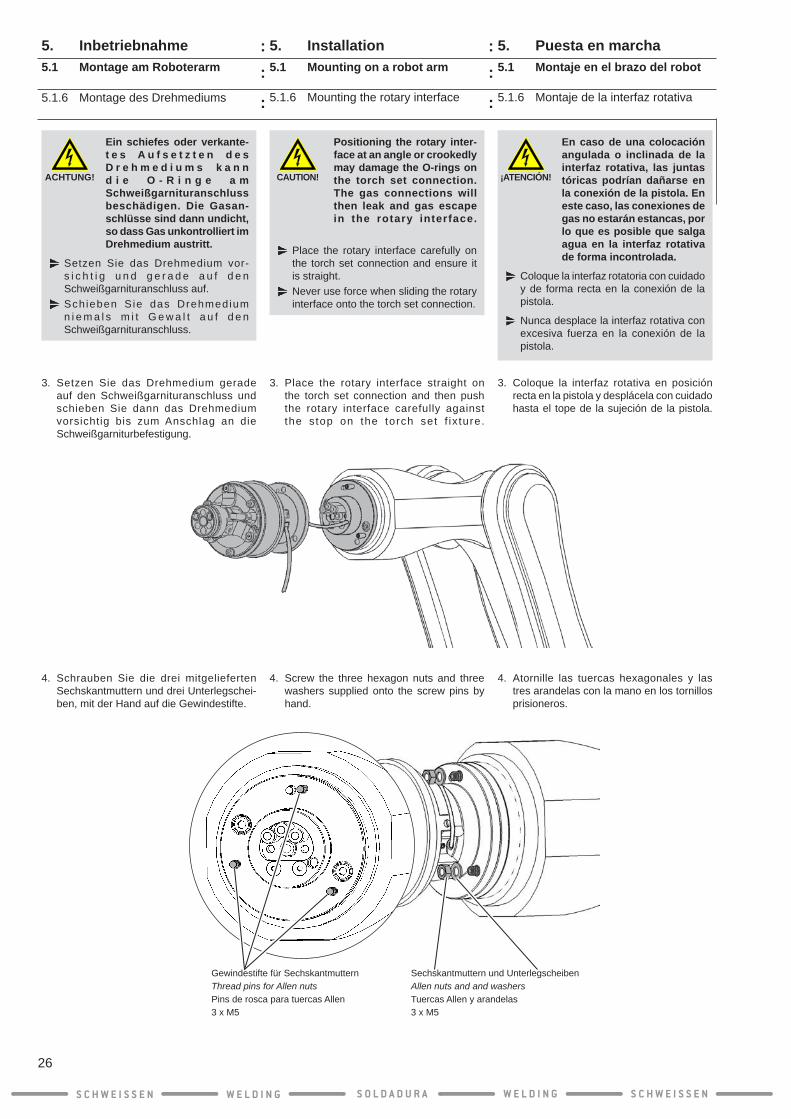
Positioning the rotary inter-face at an angle or crookedly may damage the O-rings on the torch set connection. The gas connections will then leak and gas escape in the rotary interface.
Place the rotary interface carefully on the torch set connection and ensure it is straight.Never use force when sliding the rotary interface onto the torch set connection.
3. Place the rotary interface straight on the torch set connection and then push the rotary interface carefully against the stop on the torch set f ix ture.
4. Screw the three hexagon nuts and three washers supplied onto the screw pins by hand.
5.1.6 Mounting the rotary interface
5. Installation5.1 Mounting on a robot arm
ACHTUNG!
Ein schiefes oder verkante- t e s A u f s e t z t e n d e s D r e h m e d i u m s k a n n d i e O - R i n g e a m Schweißgarnituranschluss beschädigen. Die Gasan-schlüsse sind dann undicht, so dass Gas unkontrolliert im Drehmedium austritt.
Setzen Sie das Drehmedium vor-s i c h t i g u n d g e r a d e a u f d e n Schweißgarnituranschluss auf.Schieben Sie das Drehmedium n i e m a l s m i t G e w a l t a u f d e n Schweißgarnituranschluss.
3. Setzen Sie das Drehmedium gerade auf den Schweißgarnituranschluss und schieben Sie dann das Drehmedium vorsichtig bis zum Anschlag an die Schweißgarniturbefestigung.
4. Schrauben Sie die drei mitgelieferten Sechskantmuttern und drei Unterlegschei-ben, mit der Hand auf die Gewindestifte.
5.1.6 Montage des Drehmediums
5. Inbetriebnahme5.1 Montage am Roboterarm
S C H W E I S S E N W E L D I N G W E L D I N GS O L D A D U R A S C H W E I S S E N
26
Sechskantmuttern und UnterlegscheibenAllen nuts and and washersTuercas Allen y arandelas3 x M5
Gewindestifte für SechskantmutternThread pins for Allen nuts Pins de rosca para tuercas Allen 3 x M5
::
:
::
:

5. Atornille las tuercas hexagonales con una llave de tornillos SW8 y con un par de 4 Nm.
INFO
Si no usa el sensor de tobera de gas, la interfaz rotativa es montada como se describe en el Apéndice D.
6. Guíe el cable del sensor de toberas de gas enlainterfazrotativaatravésdelorificio.
7. Desplace la carcasa hasta el tope sobre la interfaz rotativa, y para poder hacerlo, guíe al mismo tiempo el cable del sensor de toberas de gas a través de la carcasa.
5.1.6 Montaje de la interfaz rotativa
5. Puesta en marcha5.1 Montaje en el brazo del robot
5. Tighten the hexagon nuts to 4 Nm with an 8 mm wrench.
INFO
If you don‘t use the gas nozzle sensor, the rotary interface will is being mounted as outlined in Attachment D.
6. Pull the gas nozzle sensor cable through the hole in the rotary interface.
7. Slide the housing against the stop over the rotary interface; guide the gas nozzle sensor cable through the housing as you do so.
5.1.6 Mounting the rotary interface
5. Installation5.1 Mounting on a robot arm
5. Schrauben Sie die Sechskantmuttern mit einem Schraubenschlüssel SW8, mit 4 Nm fest.
INFO
Wenn Sie den Gasdüsensensor nicht verwenden, wird das Drehmedium, wie in Anhang D beschrieben, fertig montiert.
6. Ziehen Sie das Gasdüsensensorkabel durch die Bohrung im Drehmedium.
7. Schieben Sie das Gehäuse bis zum Anschlag über das Drehmedium, führen Sie dabei das Gasdüsensensorkabel mit durch das Gehäuse.
5.1.6 Montage des Drehmediums
5. Inbetriebnahme5.1 Montage am Roboterarm
S C H W E I S S E N W E L D I N G W E L D I N GS O L D A D U R A S C H W E I S S E N
27
= 4 Nm
::
:
::
:

8. Pinche con un punzón o atornille con un taladro un agujero (ø 2 mm) en la protección de goma para guiar el cable del sensor de toberas de gas.
9. Guíe el cable del sensor de toberas de gas por el agujero en la protección de goma y colóquelo sobre la interfaz rotativa.
INFO
¡Tenga en cuenta las indicaciones de montaje del robot Motoman-Yaskawa con protección frente a pandeo en el sexto eje del anexo A (2. - 4.)!
5.1.6 Montaje de la interfaz rotativa
5. Puesta en marcha5.1 Montaje en el brazo del robot
8. Use a hollow punch or drill bit (dia. 2 mm) to make a hole in the dust boot through which you can pull the gas nozzle sensor cable.
9. Pull the gas nozzle sensor cable through the hole in the dust boot and place it onto the rotary interface.
INFO
Please observe the mounting notes for Motoman-Yaskawa robots with bend protection on the 6th axis in appendix A (2. - 4.)!
5.1.6 Mounting the rotary interface
5. Installation5.1 Mounting on a robot arm
8. Stechen sie mit einem Locheisen oder bohren Sie mit einem Bohrer ein Loch (ø 2mm) in die Manschette, durch das Sie das Gasdüsensensorkabel durchziehen können.
9. Ziehen Sie das Gasdüsensensorkabel durch das Loch in der Manschette und set-zen Sie diese auf das Drehmedium.
INFO
B e a c h t e n S i e b i t t e d i e Montagehinweise für Motoman-Yaskawa-Roboter mit Knickschutz an der 6. Achse im Anhang A (2. - 4.)!
5.1.6 Montage des Drehmediums
5. Inbetriebnahme5.1 Montage am Roboterarm
S C H W E I S S E N W E L D I N G W E L D I N GS O L D A D U R A S C H W E I S S E N
28
::
:
::
:

5.1.7 Montaje del cabezal de pistola
5. Puesta en marcha5.1 Montaje en el brazo del robot
1. Atornille la tubuladora DIX MES 300/500 manualmente en el cabezal de pistola.
2. Apriete la tubuladora con una llave de tor-nillos SW 8 (manualmente).
3. Coloque el cabezal de pistola en las uni-dades de conexión de la interfaz rotativa y atornille la tuerca de unión manualmente.
¡ADVERTENCIA!
Si la llave para tuercas ranura-das DIX SLAT 4 se fija al revés pueden provocarse lesiones en las manos o es posible que se dañe la llave para tuercas ranuradas o la tuerca de unión.
Asegúrese de que la llave para tuercas ranuradas DIX SLAT 4 esté colocada correctamente sobre la tuerca de unión.
4. Apriete bien la tuerca de unión con la llave para tuercas ranuradas DIX SLAT 4 para garantizar el asiento correcto del cabezal de pistola.
1. Screw the DIX MES 300/500 connect-ing piece by hand into the torch head.
2. Tighten the connecting piece (hand-tight) with an 8 mm wrench.
3. P l a c e t h e t o r c h h e a d o n t h e connection body of the rotary interface and t ighten the cap nut by hand.
WARNING!
Incorrect positioning of the DIX SLAT 4 hook spanner may cause hand injuries and/or damage the hook spanner or the cap nut!
Ensure that the DIX SLAT 4 sits correctly on the cap nut.
4. UsetheDIXSLAT4hookspannertofirmlytighten the cap nut to ensure secure seating of the torch head.
5.1.7 Mounting the torch head
5. Installation5.1 Mounting on a robot arm
5.1.7 Montage des Pistolenkopfes
5. Inbetriebnahme5.1 Montage am Roboterarm
1. Schrauben Sie den Stutzen DIX MES 300/500 mit der Hand in den Pistolenkopf ein.
2. Ziehen Sie den Stutzen mit einem Schrau-benschlüssel SW 8 fest (Handfest).
3. Setzen Sie den Pistolenkopf auf den Anschlusskörper des Drehmediums und schrauben Sie die Überwurfmutter mit der Hand fest.
WARNUNG!
Ein verkehrtes Ansetzten des Hakenschlüssel DIX SLAT 4 kann zu Handverletzungen f ü h r e n u n d / o d e r d e n Hakenschlüssel oder die Überwurfmutter beschädi-gen !
A c h t e n s i e d a r a u f , d a s s d e r Hakenschlüssel DIX SLAT 4 richtig auf der Überwurfmutter sitzt.
4. Ziehen Sie mit dem Hakenschlüssel DIX SLAT 4 die Überwurfmutter richtig fest, um einen sicheren Sitz des Pistolenkopfes zu gewährleisten.
S C H W E I S S E N W E L D I N G W E L D I N GS O L D A D U R A S C H W E I S S E N
29
Stutzen DIX MES 300/500Connecting piece DIX MES 300/500Tubuladora DIX MES 300/500
= Handfest= hand tight= manualmente
::
:
::
:

1. Desatornille la tobera de gas del cabezal de pistola.
2. Desatornille el casquillo roscado del cabezal de pistola con la llave especial DINSE DIX SSL 1/2.
3. Saque la punta de contacto.
5.1.8 Inserción de la espiral de guía de hilo
5. Puesta en marcha5.1 Montaje en el brazo del robot
1. Unscrew the gas nozzle from the torch head.
2. Loosen the screw base on the torch head with the DINSE DIX SSL 1/2 special wrench.
3. Pull out the contact tip.
5.1.8 Insert liner
5. Installation5.1 Mounting on a robot arm
5.1.8 Drahtführungsspirale einführen
1. Schrauben S ie d ie Gasdüse vom Pistolenkopf ab.
2. L ö s e n S i e d e n G e w i n d e s o c k e l am P is to lenkop f m i t dem DINSE Spezialschlüssel DIX SSL 1/2.
3. Ziehen Sie die Kontaktspitze heraus.
5. Inbetriebnahme5.1 Montage am Roboterarm
S C H W E I S S E N W E L D I N G W E L D I N GS O L D A D U R A S C H W E I S S E N
30
::
:
::
:

5.1.8 Inserción de la espiral de guía de hilo
5. Puesta en marcha5.1 Montaje en el brazo del robot
¡ATENCIÓN!
Una espiral de guía de hilo con un diámetro interior demasiado pequeño impide la extracción del hilo. Un diáme-tro interior demasiado grande puede tener una influencia negativa en la calidad de la costura de soldadura.
Controle el diámetro interior de la espi-ral de guía de hilo y cámbiela en caso necesario por una espiral de guía de hilo adecuada.
Consulte las listas de piezas de des-gaste y repuesto para seleccionar la espiral de guía de hilo adecuada.
¡ATENCIÓN!
Las rebabas afiladas en la punta de la espiral de guía de hilo pueden dañar el con-ducto de transporte de hilo.
Asegúrese de introducir las espirales de guía de hilo cortadas por DINSE por el lado desbarbado en la pistola.
Asegúrese de que en las espirales de guía de hilo que corte usted mismo se desbarbe primero el extremo y se intro-duzca la espiral de guía de hilo con el lado desbarbado en la pistola.
¡ATENCIÓN!
En las interfaces rotativas con freno de hilo DIX RET 341 F(S) (WB 1) deberá tener en cuenta que las espirales de guía de hilo se deben introducir en dos piezas (vea el anexo E).
4. Inserte la espiral de guía de hilo en el cabe-zal de pistola y desplace la espiral de guía de hilo hasta el tope en el devanador de hilo.
5.1.8 Insert liner
5. Installation5.1 Mounting on a robot arm
CAUTION!
A liner with too small an inside diameter interferes with the wire feeding. Too large an inside diameter may have a negative effect on the weld quality.
Check the inside diameter of the liner and replace it with a matching liner if necessary.Refer to the spare and wear parts list to select the matching liners.
CAUTION!
Sharp burs at the tip of the liner may destroy the wire feed hose.
Ensure that you insert liners cut to length by DINSE into the torch set with the groundoffsidefirst.Ensure with liners you have cut to size yourselfthatyoufirstdeburoneendandthen insert the liner with the deburred side into the torch set.
CAUTION!
Please note with the rotary interfaces with wire brake DIX RET 341 F(S) (WB 1) that the liner needs to be inserted in 2 parts (see Appendix E).
4. Insert the liner into the torch head and slide the liner against the stop in the wire feeder.
ACHTUNG!
Eine Drahtführungsspirale m i t z u k l e i n e m Innendurchmesser behindert die Drahtförderung. Ein zu großer Innendurchmesser kann negativen Einfluss auf die Schweißnahtqualität haben.
Kontrollieren Sie den Innendurchmesser der Drahtführungsspirale und tau-schen diese gegebenenfalls gegen eine passende Drahtführungsspirale aus.Schauen Sie in die Ersatz- und Verschleißteilelisten, um die passen-den Drahtführungsspirale auszuwählen.
ACHTUNG!
S c h a r f e G r a t e a n d e r Spitze der Drahtführungs- s p i r a l e k ö n n e n d e n Drahtförderschlauch zer-stören.
A c h t e n S i e d a r a u f , d a s s S i e be i von der DINSE abgelängte Drahtführungsspiralen, diese mit der abgeschli ffenen Seite in die Schweißgarnitur einführen.Achten Sie darauf, dass Sie bei selbst zugeschnittenen Drahtführungsspiralen, ein Ende erst entgraten und die Drahtführungsspirale mit der entgrateten Seite in die Schweißgarnitur einführen.
ACHTUNG!
Beachten Sie bitte bei den Drehmedien mit Drahtbremse DIX RET 341 F(S) (WB 1), dass die Drahtführungsspirale in 2 Teilen eingeführt werden muß (siehe Anhang E).
5.1.8 Drahtführungsspirale einführen
5. Inbetriebnahme5.1 Montage am Roboterarm
4. Führen Sie die Drahtführungsspirale in den Pistolenkopf ein und schieben Sie die Drahtführungsspirale bis zum Anschlag im Drahtvorschub.
S C H W E I S S E N W E L D I N G W E L D I N GS O L D A D U R A S C H W E I S S E N
31
::
:
::
:
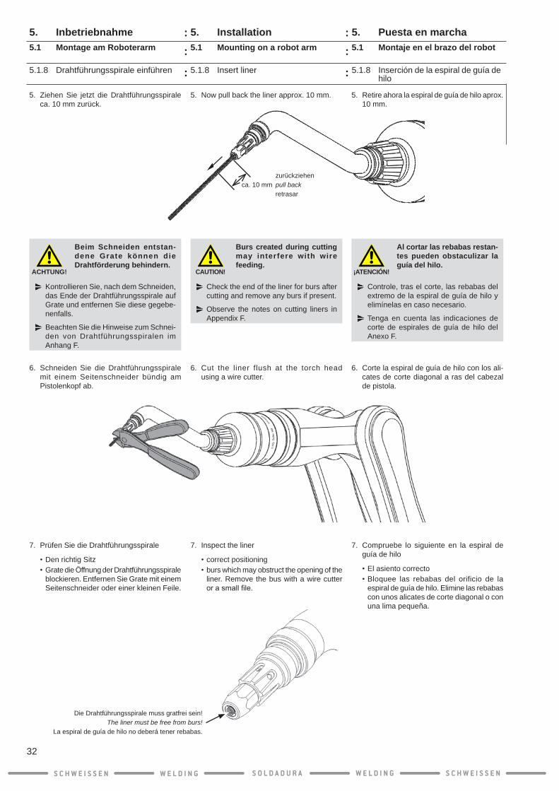
5. Retire ahora la espiral de guía de hilo aprox. 10 mm.
¡ATENCIÓN!
Al cortar las rebabas restan-tes pueden obstaculizar la guía del hilo.
Controle, tras el corte, las rebabas del extremo de la espiral de guía de hilo y elimínelas en caso necesario.
Tenga en cuenta las indicaciones de corte de espirales de guía de hilo del Anexo F.
6. Corte la espiral de guía de hilo con los ali-cates de corte diagonal a ras del cabezal de pistola.
7. Compruebe lo siguiente en la espiral de guía de hilo
•El asiento correcto•Bloquee las rebabas del orificio de la
espiral de guía de hilo. Elimine las rebabas con unos alicates de corte diagonal o con una lima pequeña.
5.1.8 Inserción de la espiral de guía de hilo
5. Puesta en marcha5.1 Montaje en el brazo del robot
5. Now pull back the liner approx. 10 mm.
5.1.8 Insert liner
5. Installation5.1 Mounting on a robot arm
CAUTION!
Burs created during cutting may interfere with wire feeding.
Check the end of the liner for burs after cutting and remove any burs if present.
Observe the notes on cutting liners in Appendix F.
6. Cut the liner flush at the torch head using a wire cutter.
7. Inspect the liner
•correct positioning•burs which may obstruct the opening of the
liner. Remove the bus with a wire cutter orasmallfile.
5. Ziehen Sie jetzt die Drahtführungsspirale ca. 10 mm zurück.
ACHTUNG!
Beim Schneiden entstan-dene Grate können die Drahtförderung behindern.
Kontrollieren Sie, nach dem Schneiden, das Ende der Drahtführungsspirale auf Grate und entfernen Sie diese gegebe-nenfalls.
Beachten Sie die Hinweise zum Schnei-den von Drahtführungsspiralen im Anhang F.
6. Schneiden Sie die Drahtführungsspirale mit einem Seitenschneider bündig am Pistolenkopf ab.
7. Prüfen Sie die Drahtführungsspirale
•Den richtig Sitz•Grate die Öffnung der Drahtführungsspirale
blockieren. Entfernen Sie Grate mit einem Seitenschneider oder einer kleinen Feile.
5.1.8 Drahtführungsspirale einführen
5. Inbetriebnahme5.1 Montage am Roboterarm
S C H W E I S S E N W E L D I N G W E L D I N GS O L D A D U R A S C H W E I S S E N
32
zurückziehenca. 10 mm pull back retrasar
::
:
::
:
Die Drahtführungsspirale muss gratfrei sein!The liner must be free from burs!
La espiral de guía de hilo no deberá tener rebabas.

8. Desplace la espiral de guía de hilo con la punta de contacto hasta el cabezal de pistola y atornille el casquillo roscado manualmente.
9. Apriete el casquillo roscado con la llave especial DINSE DIX SSL 1/2 (manual-mente).
10. Atornille la tobera de gas de nuevo en el cabezal de pistola y apriete la tobera de gas (manualmente).
5.1.8 Inserción de la espiral de guía de hilo
5. Puesta en marcha5.1 Montaje en el brazo del robot
8. Slide the liner with the contact tip into the torch head and screw on the screw base by hand.
9. Tighten the screw base (hand-tight) using the DINSE DIX SSL 1/2 special wrench.
10. Screw the gas nozzle back on the torch head and tighten it (hand-tight).
5.1.8 Insert liner
5. Installation5.1 Mounting on a robot arm
8. Schieben Sie die Drahtführungsspirale mit der Kontaktspitze in den Pistolenkopf und schrauben Sie den Gewindesockel mit der Hand an.
9. Drehen Sie den Gewindesockel mit dem DINSE Spezialschlüssel DIX SSL 1/2 fest (Handfest).
10. Schrauben Sie die Gasdüse wieder auf den Pistolenkopf und drehen Sie die Gasdüse fest (Handfest).
5.1.8 Drahtführungsspirale einführen
5. Inbetriebnahme5.1 Montage am Roboterarm
S C H W E I S S E N W E L D I N G W E L D I N GS O L D A D U R A S C H W E I S S E N
33
= Handfest= hand tight= manualmente
::
:
::
:
= Handfest= hand tight= manualmente

1. Desplace la pinza de contacto DIX K 180 ME en el cabezal.
2. Introduzca el cable del sensor de toberas de gas en la pinza de contacto y doble la pinza ligeramente hacia arriba.
3. Gire la pinza de contacto de forma que el cable del sensor de toberas de gas quede avellanado en el tapón roscado y desplace la pinza de contacto sobre la pieza de conexión.
4. Fije la pinza de conectado con el tornillo prisionero (M3 x 5 mm) en la pieza de conexión.
5.1.9 Montaje del cable del sensor de toberas de gas
5. Puesta en marcha5.1 Montaje en el brazo del robot
1. Slide the DIX K 180 ME contact clamp onto the torch head.
2. Plug the gas nozzle sensor cable on the contact clamp and bend the clamp slightly upward.
3. Turn the contact clamp so that the gas nozzle sensor cable rests in a hollow of the screw cap and slide the contact clamp onto the connection.
4. Fix the contact clamp with the screw pin (M3 x 5 mm) on the connection.
5.1.9 Mount the gas nozzle sensor cable
5. Installation5.1 Mounting on a robot arm
5.1.9 Gasdüsensensorkabel montieren
1. Schieben Sie die Kontaktklemme DIX K 180 ME auf den Pistolenkopf.
2. Stecken Sie sie das Gasdüsensensorkabel auf die Kontaktklemme und biegen Sie die Klemme etwas nach oben.
3. Drehen Sie die Kontaktklemme so hin, dass das Gasdüsensensorkabel in einer Senke der Schraubkappe liegt und schieben Sie die Kontaktklemme auf das Anschlussstück.
4. Fixieren Sie die Kontaktklemme mit dem Gewindestift (M3 x 5 mm) am Anschluss-stück.
5. Inbetriebnahme5.1 Montage am Roboterarm
S C H W E I S S E N W E L D I N G W E L D I N GS O L D A D U R A S C H W E I S S E N
34
= Handfest= Hand-tight= manualmente
GewindestiftScrew pinTornillo prisioneroM3 x 5 mm
::
:
::
:

5.1.10 Comprobación de recorridos
5. Puesta en marcha5.1 Montaje en el brazo del robot
INFO
Con el sistema de soldadura DINSE ECO.torch se pueden realizar todos los recorridos del robot. La girabilidad ilimitada de la interfaz rotativa ofrece una excelente accesibilidad de los componentes.La extrema capacidad de movimiento de la pistola permite extender y doblar de cualquier forma el brazo del robot.
Compruebe si el robot se puede desplazar correctamente hacia la posición deseada y si se puede girar el cabezal de pistola correc-tamente.
Realice por su propia seguridad un control del peso y de la palanca.
5.1.10 Check travel
5. Installation5.1 Mounting on a robot arm
INFO
Travel of the robot in any direction is possible with the DINSE ECO.torch welding system. The rotation capability of the rotary interface provides excellent component access.Because of its extreme flexibility, the torch set follows any bending or exten-sion of the robot arm.
Check that the robot can travel without fault to any desired posi-tion and that the torch head rotates without problem.
For your own safety, perform a check of the weight and lever relationships.
5.1.10 Verfahrwege prüfen
INFO
M i t d e m D I N S E E C O . t o r c h Schweißsystem sind alle Verfahrwege des Roboters möglich. Die Drehbarkeit des Drehmediums sorgt für eine sehr gute Bauteil-Zugänglichkeit. Die Schweißgarnitur macht durch ihre extreme Beweglichkeit jede Beugung ode r S t reckung des Roboterarms mit.
Prüfen Sie ob der Roboter fehlerfrei in jede beliebige Position gefahren werden kann und ob sich der Pistolen kopf einwandfrei dreht.
Führen Sie zu Ihrer eigenen Sicherheit eine Kontrolle der Gewichts- und Hebelverhältnisse durch.
5. Inbetriebnahme5.1 Montage am Roboterarm
S C H W E I S S E N W E L D I N G W E L D I N GS O L D A D U R A S C H W E I S S E N
35
::
:
::
:

6. Indicaciones de mantenimiento
El juego de interfaz de giro es en gran parte libre de mantenimiento debido a la utilización de piezas de alta calidad. Para garantizar un funcionamiento sin pertur-baciones, recomendamos llevar a cabo cont-roles regulares. La frecuencia de los controles individuales y de los trabajos de mantenimiento se ajusta según las condiciones operativas de los juegos de interfaz de giro. Cada usuario debería crear por lo tanto su propio plan de mantenimiento.
Antes de cualquier trabajo de control o de mantenimiento, desconectar el enchufe!
Asegúrese de que nadie encienda la fuente de energía durante el manteni-miento!Desconecte el conector compacto, como así también, de ser necesario, el conector de cables de mando del juego de la fuente de energía!
¡ADVERTENCIA!
Peligro de lesiones en los ojos debido al desprendi-miento de virutas, a la abra-sión de electrodos de cable y a salpicaduras de soldadura al limpiar el juego de solda-dura con aire comprimido!
Utilice siempre gafas protectoras o una visera.
Para garantizar un funcionamiento óptimo, deben llevarse a cabo los siguientes trabajos en intervalos regulares:
● Revisión visual general del juego por posib-les daños y señales de desgaste.
● Verificarquetodaslasconexionesdescon-ectables tengan un contacto seguro
● Remover la abrasión de material del cable (dependiente de la calidad del cable y del volumen de entrega) debido al soplado de la espiral de guía de hilo y al de la manguera de alimentación del cable con aire comprimido (máx. 6 bar).
● Evaluar si se debe cambiar:•La punta de contacto•La tobera de gas•Las espirales de guía del hilo•El distribuidor de gas• la puesta de la tobera de gas •Y todos los otros consumibles
relevantes
6. Maintenance instructions
To help ensure trouble-free functioning, the following inspections should be made at regular intervals:
● Conduct a general visual inspection of the torch set for signs of any damage or wear.
● Check all removable connectors to ensure they are properly seated.
● Remove any abraded wire (depending on wire quality and feed quantity) by blowing out the liner and conduit hose with compressed air (max. 6 bar).
● Replace the following items as needed:•Contact tip•Gas nozzle•Liner•Clamp nut •Gas diffuser•Gas nozzle insert•and all other relevant consumables
Aways unplug the torch set before starting any inspec-tion or maintenance work!
During maintenance, make sure that nobody switches on the voltage supply!Disconnect the compact plug and, if needed, the torch set‘s control-cable plug from the voltage supply!
Due to our use of high-grade components, the rotary interface should require very little maintenance. However, we recommend for you to conduct regular inspections to ensure continued functionality. Individual checks and maintenance tasks should be performed at regular intervals, depending on the conditions under which the rotary interface is operated. We recommended that each individual user create an individual maintenance schedule.
WARNING!
Eye injury can occur due to flying chips, wire electrode abrasion, and weld spatters produced during blow-out of the torch set from com-pressed air!
Always wear safety goggles or a visor while using this torch set.
6. Wartungshinweise
Um eine einwandfreie Funktion zu gewährleis-ten, müssen folgende Arbeiten in regelmäßigen Abständen durchgeführt werden:
● Allgemeine Sichtprüfung der Garnitur auf Schäden und Abnutzungserscheinungen.
● Alle lösbaren Verbindungen auf korrekten Sitz überprüfen
● Materialabrieb des Drahts, (abhängig von der Drahtqualität und der Fördermenge) durch Ausblasen der Drahtführungsspirale und des Drahtförderschlauches mit Druckluft (max. 6 bar) entfernen.
● Nach eigenem Ermessen wechseln:•Kontaktspitze•Gasdüse•Drahtführungsspirale•Spannmutter•Gasverteiler•Gasdüseneinsatz•und alle anderen relevanten
Verbrauchsmaterialen
Bei jeder Kontroll- und War-tungsarbeit unbedingt den Netzstecker ziehen!
Stellen Sie sicher, dass während der War-tung niemand die Spannungsversorgung einschaltet!Ziehen Sie den Kompaktstecker, sowie ggf. den Steuerleitungsstecker der Gar-nitur von der Spannungsversorgung ab!
Das Drehmedium ist durch die Verwendung hochwertiger Bauteile weitgehend wartungsfrei. Um einen störungsfreien Betrieb zu gewähr-leisten, empfehlen wir regelmäßig Kontrollen durchzuführen.DieHäufigkeit der einzelnenKontrollen und Wartungsarbeiten richtet sich hierbei nach den Einsatzbedingungen des Drehmediums. Jeder Anwender sollte sich daher einen eigenen Wartungsplan erstellen.
WARNUNG!
Gefahr von Augenver - letzungen durch umher-fliegende Späne, Draht-e l e k t r o d e n a b r i e b u n d S c h w e i ß s p r i t z e r b e i m A u s b l a s e n d e r Schweißgarnitur mit Druck-luft!
Tragen Sie immer eine Schutzbrille oder -visier.
S C H W E I S S E N W E L D I N G W E L D I N GS O L D A D U R A S C H W E I S S E N
36
: :
● Mantener limpias las conexiones del cabe-zal de la pistola y los cables de conexión, ya que las conexiones sucias ocasionan dificultades de contacto y el juego parasoldadura ya no podrá funcionar correc-tamente.
● Si cambia con frecuencia el cabezal de la pistola, cambie eventualmente los anillos de junta usados o defectuosos (anillo en O) del cabezal de la pistola a tiempo.
● Proteger el juego de demasiados esfuerzos de pandeo para aumentar la durabilidad.
● Comprobar el asiento correcto o si hay daños en la protección de goma.
● Control del peso y de la palanca durante el cambio de herramienta.
● Comprobación de las sujeciones y de las cargas en el sistema.
INFO
Recomendamos enviar toda la interfaz rotativa una vez al año a DINSE para su mantenimiento y conservación.
Tenga en cuenta también las indicaciones de mantenimiento para la alimentación del cable y de los otros componentes, como por ejemplo la fuente de energía, el sistema de refrigeración y el sistema de bobinas.
INFO
Utilizar solamente componentes y pie-zas de repuesto originales de DINSE!
6. Indicaciones de mantenimiento6. Maintenance instructions
● Always keep the torch head connections and the connection element clean, as dirty connectors can worsen contact and nega-tively affect the torch set‘s performance.
● If the torch head is changed frequently, be sure to regularly replace its seal rings (O-rings) in order to avoid damage or ex-cessive wear.
● To increase the life span of your torch set, do not subject the torch set to stressful conditions such as excessive bending.
● Check the dust boot for correct seating and damage.
● Check the weight and lever relationships when changing tools.
● Check the fasten ing connect ions and loads generated in the system.
INFO
We recommend sending the complete rotary interface to DINSE for servicing and maintenance.
Always observe the maintenance instructions for the wire feeder and other components, in-cluding the power source as well as the cooling and spool systems.
INFO
Use only original components and spare parts from DINSE!
6. Wartungshinweise
● Stets die Anschlüsse vom Pistolenkopf und Anschlusskörper sauber halten, wei l verschmutzte Anschlüsse zu Kontaktschwierigkeiten führen und die Schweißgarnitur nicht mehr richtig arbeitet.
● BeihäufigemWechseldesPistolenkopfseventuell schadhafte oder abgenutzte Dichtungsringe (O-Ringe) am Pistolenkopf rechtzeitig austauschen.
● D i e G a r n i t u r v o r ü b e r m ä ß i g e r Knickbeanspruchung bewahren, um die Lebensdauer zu erhöhen.
● Manschette auf korrekten Sitz und Beschä-digungen überprüfen.
● K o n t r o l l e d e r G e w i c h t s - u n d Hebelverhältnisse beim Werkzeugwechsel.
● Überprüfung der Befestigungen und auf-tretenden Belastungen für das System.
INFO
Wir empfehlen jährlich das vollständige Drehmedium zur Wartung und Instand-haltung an DINSE zu schicken.
Beachten Sie bitte auch die Wartungshinweise zum Drahtvorschub und den anderen Kom-ponenten wie z.B. Stromquelle, Kühl- und Spulensystem.
INFO
Nur original DINSE Komponenten und Ersatzteile verwenden!
S C H W E I S S E N W E L D I N G W E L D I N GS O L D A D U R A S C H W E I S S E N
37
: :
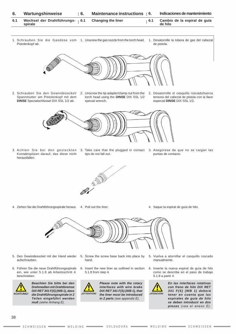
6.1 Cambio de la espiral de guía de hilo
1. Desatornille la tobera de gas del cabezal de pistola.
2. Desatornille el casquillo roscado/tuerca tensora del cabezal de pistola con la llave especial DINSE DIX SSL 1/2.
3. Asegúrese de que no se caigan las puntas de contacto.
4. Saque la espiral de guía de hilo.
5. Vuelva a atornillar el casquillo roscado manualmente.
6. Inserte la nueva espiral de guía de hilo como se describe en el paso de trabajo 5.1.8 a partir 4.
6. Indicaciones de mantenimiento
¡ATENCIÓN!
En las interfaces rotativas con freno de hilo DIX RET 341 F(S) (WB 1) deberá tener en cuenta que las espirales de guía de hilo se deben introducir en dos piezas (vea el anexo E).
6.1 Changing the liner
6. Maintenance instructions
1. Unscrew the gas nozzle from the torch head.
2. Unscrew the tip adapter/clamp nut from the torch head using the DINSE DIX SSL 1/2 special wrench.
3. Take care that the plugged in contact tips do not fall out.
4. Pull out the liner.
5. Screw the screw base back into place by hand.
6. Insert the new liner as outlined in section 5.1.8 from step 4.
¡ATTENTION!
Please note with the rotary interfaces with wire brake DIX RET 341 F(S) (WB 1), that the liner must be introduced in 2 parts (see appendix E).
6.1 Wechsel der Drahtführungs-spirale
6. Wartungshinweise
1. Schrauben S ie d ie Gasdüse vom Pistolenkopf ab.
2. Schrauben Sie den Gewindesockel/Spannmutter am Pistolenkopf mit dem DINSE Spezialschlüssel DIX SSL 1/2 ab.
3. A c h t e n S i e b e i d e n g e s t e c k t e n Kontaktspitzen darauf, das diese nicht herausfallen.
4. Ziehen Sie die Drahtführungsspirale heraus.
5. Den Gewindesockel mit der Hand wieder aufschrauben.
6. Führen Sie die neue Drahtführungsspirale ein, wie unter 5.1.8 ab Arbeitsschritt 4. beschrieben.
ACHTUNG!
Beachten Sie bitte bei den Drehmedien mit Drahtbremse DIX RET 341 F(S) (WB 1), dass die Drahtführungsspirale in 2 Teilen eingeführt werden muß (siehe Anhang E).
S C H W E I S S E N W E L D I N G W E L D I N GS O L D A D U R A S C H W E I S S E N
38
::
::

6.2 Reparaciones en el juego de soldadura
INFO
Tenga en cuenta que las reparaciones las puede realizar sólo DINSE o un electricista contratado por usted!
6. Indicaciones de mantenimiento6. Maintenance instructions6.2 Repairing torch sets
INFO
Please note that repairs should generally be performed only by DINSE or qualified electricians appointed by DINSE!
6.2 Schweißgarnitur reparieren
6. Wartungshinweise
INFO
Beachten Sie bitte, dass Reparaturen generell nur von DINSE oder von ihr beauftragte Elektrofachkräfte ausge-führt werden dürfen!
S C H W E I S S E N W E L D I N G W E L D I N GS O L D A D U R A S C H W E I S S E N
39
::
::

7. Solución del problema
Problema Causa posible Solución
Se extrae el cable de manera brusca Espirales de guía del cable atascadas o dañadas
Limpie o cambie las espirales de guía del hilo
Punta de contacto con perforación de-masiado pequeña
Utilice una punta de contacto que con-cuerde con el cable
Espirales de guía del cable con diámetro interior demasiado pequeño
Utilice una espiral de guía del hilo que concuerde con el cable
Línea de control desconectada Conecte la línea de control en la alimen-tación del cable
El devanado longitudinal de la bobina de hilo empleada no está en buen estado
Sustituya la bobina de hilo
La bobina de hilo está deformada o rota Sustituya la bobina de hilo
7. Troubleshooting
Malfunction Possible causes Remedy
Wire feed is jerky Liner is blocked or damaged Clean or replace the liner
Contact tip‘s drill-hole is too small Use a contact tip which matches the wire
Liner‘s inner diameter is too small Use a liner which matches the wire
Control line is disconnected Connect the control line to the wire feeder
The layer reeling of the wire spool used is defective
Replace the spool.
The spool is deformed or chipped Replace the spool.
The brake on the spool is set too tight Correct the setting of the spool brake
7. Störungsbehebung
Störung Mögliche Ursache Behebung
Draht wird nicht oder ruckartig gefördert Verstopfte oder beschädigte Drahtführungsspirale
Reinigen oder wechseln Sie die Drahtführungsspirale aus
Kontaktspitze mit zu kleiner Bohrung Verwenden Sie eine auf den Draht abge-stimmte Kontaktspitze
Drahtführungsspirale mit zu kleinem Innendurchmesser
Verwenden Sie eine auf den Draht abge-stimmte Drahtführungsspirale
Steuersignal nicht vorhanden Schließen Sie den Drahtvorschub an der Spannungsversorgung an
Die Lagenspulung der verwendeten Drahtspule ist defekt
Wechseln Sie die Drahtspule aus
S C H W E I S S E N W E L D I N G W E L D I N GS O L D A D U R A S C H W E I S S E N
40
: :

7. Solución del problema
Problema Causa posible Solución
Se extrae el cable de manera brusca Los frenos de la bobina de hilo están demasiado duros
Corrija el ajuste de los frenos de la bobi-na de hilo
7. Troubleshooting7. Störungsbehebung
Störung Mögliche Ursache Behebung
Draht wird nicht oder ruckartig gefördert Die Drahtspule ist verformt oder ausge-brochen
Wechseln Sie die Drahtspule aus
Die Bremse der Drahtspule ist zu fest eingestellt
Korrigieren Sie die Einstellung der Drahtspulenbremse
S C H W E I S S E N W E L D I N G W E L D I N GS O L D A D U R A S C H W E I S S E N
41
: :

Apéndice A
Montaje de la protección frente a pandeo en Motoman-Yaskawa-Robots
1. Coloque la protección frente a pandeo sobre la pistola antes de introducir la pistola en el sexto eje del brazo del robot.
3. Desplace la protección frente a pandeo sobre el casquillo de protección frente a pandeo.
4. Atornille la protección frente a pandeo con el tornillo de hexágono interior suministrado (M6 x 25 mm) con una llave de hexágono interior SW 5, con un par de 3 Nm.
5. Continúe ahora como se describe en el paso 8. en “5.1.7 Montaje del cabezal de la pistola” en la página 29.
2. Coloque la segunda pieza del casquillo de protección frente a pandeo alrededor de la pistola y una las piezas.
Appendix A
Mounting the bend protection at Motoman-Yaskawa-Robots
1. Pull the bend protection over the torch set before inserting the torch set into the 6th axis of the robot arm.
2. Position the two parts of the bend protection sleeve around the torch set and squeeze the bend protection sleeve together.
3. Slide the bend protection over the bend protection sleeve.
4. Tighten the bend protection to 3 Nm with the hexagon socket screws (M6 x 25 mm) supplied using a 5 mm hexagon key.
5. Now proceed as outlined in step 8 of “5.1.7 Assembly of the torch head” on page 29.
Montage des Knickschutzes bei Motoman-Yaskawa-Robotern
Anhang A
1. Ziehen Sie den Knickschutz über die Schweiß- garnitur, bevor Sie die Schweißgarnitur in die 6. Achse des Roboterarms einführen.
3. Schieben Sie den Knickschutz über die Knickschutzhülse.
4. Schrauben Sie den Knickschutz mit der mitgelieferten Innensechskantschraube (M6 x 25 mm) mit einem Innensechskants-chlüssel SW 5, mit 3 Nm, fest.
Gehen Sie jetzt weiter vor wie in Schritt 8. unter „5.1.7 Montage des Pistolenkopfs“ auf Seite 29 beschrieben.
2. Legen Sie die zwei Teile der Knickschutzhülse um die Schweißgarnitur und drücken Sie die Knickschutzhülse zusammen.
S C H W E I S S E N W E L D I N G W E L D I N GS O L D A D U R A S C H W E I S S E N
42
:
:
:
:

2. Atornille la brida de adaptación con una llave de hexágono interior SW 4 y los tor-nillos de hexágono interior suministrados, con un par de 5 Nm.
Continúe ahora como se describe en el pas. en “5.1.2 Montaje de la brida de adaptación”.
Apéndice B
Montaje de la platina adaptadora en ABB-Robots
1. Coloque la brida adicional de adaptación sobre la brida del brazo del robot. Alinee la brida de adaptación en el pin de posici-ón.
INFO
¡El pin de posición debe estar en la parte superior!
Appendix B
Mounting theaddingadapterflangeatABB-Robots
2. Tightentheadapterflangeto5Nmwitha 4 mm hexagon key and the hexagon socket screws supplied.
Now proceed as outlined in step 2 of “5.1.2 Mounting the adapter flange”.
1. Placetheadditionaladapterflangeontheflangeof therobotarm.Aligntheadapterflange on the position pin at the same time.
INFO
The position pin must be at the top!
Anhang B
MontagedesZusatzadapterflanschesbei ABB-Robotern
2. SchraubenSiedenAdapterflanschmiteinemInnensechskantschlüssel SW 4 und den mitgelieferten Innensechskantschrauben, mit 5 Nm, fest.
Gehen Sie jetzt weiter vor wie in Schritt 2. unter „5.1.2 Montage des Adapterflansches“ beschrieben.
1. SetzenSiedenzusätzlichenAdapterflanschauf den Flansch des Roboterarms. Rich-ten Sie dabei den Adapterflansch am Positionspin aus.
INFO
Der Positionpin muss oben stehen!
S C H W E I S S E N W E L D I N G W E L D I N GS O L D A D U R A S C H W E I S S E N
43
:
:
:
:
Positionpinposition pinpin de posición
Innensechskantschrauben Allen socket screwsTornillo de cabeza Allen4 x M6 x 12 mm
= 5 Nm

Apéndice C
Puertos del módulo de protección DIX REMO 101
Appendix C
Ports of the protection module DIX REMO 101
Anhang C
Anschlüsse des Schutzmoduls DIX REMO 101
S C H W E I S S E N W E L D I N G W E L D I N GS O L D A D U R A S C H W E I S S E N
44
Prüfgas zur Garnitur(Schlauchsteck-Anschluß ø 4mm)Test gas to set(Hose plug connection dia. 4 mm)Gas de prueba a la pistola(Conexión enchufe manguera ø 4 mm)
Ausblasen "Eingang"(Schlauchsteck-Anschluß ø 8mm) Blow out “Intake”(Hose plug connection dia. 8 mm)Soplado “Entrada”(conexión enchufe manguera ø 8 mm)
Ausblasen "Ausgang"(Schlauchsteck-Anschluß ø 8mm) Blow out “Outlet”(Hose plug connection dia. 8 mm)Soplado “Salida”(Conexión enchufe manguera ø 8 mm)
Ausblasventil 24 VDCKollisionsschutz (Signal)(Anschluß für Kabel DIX REAK 100-10)Blow out valve 24 VDCCollision protection (signal)(Connection for cable DIX REAK 100-10)Válvula de soplado 24 VCCProtección anticolisión (señal)(Conexión para cable DIX REAK 100-10)
:
:
:
:

Apéndice C
Puerto asignación DIX REMO 101
¡ATENCIÓN!
Una conexión fija insufici-ente provocará daños en la conexión e influirá en las propiedades de la soldadura.
Asegúrese de que todas las conexiones tengan el contacto correcto.
Appendix C
Port assignment DIX REMO 101
CAUTION!
An insufficiently firm connec-tion causes damage to the connection and affects the welding properties.
Ensure good contact with all connections
Anhang C
Anschlussbelegung des Schutzmoduls DIX REMO 101
Schließen Sie die Leitungen gemäß den Verdrahtungsplänen an.
ACHTUNG!
Eine unzureichend feste Verbindung führt zur Beschä-digung des Anschlusses und be-einträchtigt die Schweiß- eigenschaften.
Achten Sie bei allen Verbindungen auf einen guten Kontakt
S C H W E I S S E N W E L D I N G W E L D I N GS O L D A D U R A S C H W E I S S E N
45
Einstellungen/Configuration/ Configuración:Drucksensor: Eingangsdruck: DurchflußgeschwindugkeitinderPrüfleitung:
ca. 1 bar5 bar
5 l/min
Pressure sensor: Intake pressure: Flow speed in the test line:
approx. 1 bar5 bar
5 l/min
Sensor de presión: Presión de entrada: Velocidaddeflujoen el conducto de prueba:
aprox. 1 bar5 bar
5 l/min
VerbindungskabelConnecting cableCable de conexiónDIX REAK 100-10 - (10m)
gelb yellow amarillo
rosa pink rojillo
Connect the leads according to the wiring diagrams.
Conecte los conductos conforme a los esque-mas de cableado.
:
:
:
:

Apéndice C
Esquema de conexión REMO 101 con gas de protección
Gas de protección
Entrada
Gas de protección
Gas de prueba
Gas de prueba para desconexión por colisión
SopladoAire comprimido extra
Avance de agua de refrigeración (azul)
Avance de agua de refrigeración (rojo)
Control de robot REAK
24VDC
REMA
Válvula magnética en el devanador de hilo (gas de protección)
¡No se controla la válvula de soplado en el REMO 101!
Appendix C
Connection plan REMO 101 with shielding gas
Shielding gas
Intake
Shielding gas
Test gas
Test gas for collision shut-down
Blowing outExtra compressed air
Cooling water flow (blue) Cooling water flow (red)
REAKrobot control
24VDC
REMA
Solenoid valve in wire feeder (shielding gas)
Blow out valve in REMO 101 is not selected!
Anhang C
Anschlussplan REMO 101 mit Schutzgas
Schutzgas
Eingang
Schutzgas
Prüfgas
Prüfgasfür Kollisions-abschaltung
AusblasenDruckluft extra
Kühlwasservorlauf(blau)
Kühlwasservorlauf(rot)
Roboter-SteuerungREAK
24VDC
REMA
Magnetventil imDrahtvorschub(Schutzgas)
Ausblasventil im REMO 101 wird nicht angesteu-ert!
S C H W E I S S E N W E L D I N G W E L D I N GS O L D A D U R A S C H W E I S S E N
46
:
:
:
:
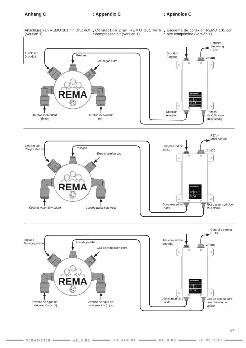
Esquema de conexión REMO 101 con aire comprimido (versión 1)
Aire comprimidoEntrada
Aire comprimidoSalida
Gas de protección extra
Gas de pruebaSopladoAire comprimido
REMA
Avance de agua de refrigeración (azul)
Avance de agua de refrigeración (rojo)
Control de robot REAK
24VDC
Gas de prueba para desconexión por colisión
Apéndice C
Connection plan REMO 101 with compressed air (Version 1)
Compressed airIntake
Compressed airOutlet
Extra shielding gas
Test gasBlowing outCompressed air
REMA
Cooling water flow (blue) Cooling water flow (red)
REAKrobot control
24VDC
Test gas for collision shut-down
Appendix C
Anschlussplan REMO 101 mit Druckluft (Version 1)
DruckluftEingang
DruckluftAusgang
Schutzgas extra
PrüfgasAusblasenDruckluft
REMA
Kühlwasservorlauf(blau)
Kühlwasservorlauf(rot)
Roboter-SteuerungREAK
24VDC
Prüfgasfür Kollisions-abschaltung
Anhang C
S C H W E I S S E N W E L D I N G W E L D I N GS O L D A D U R A S C H W E I S S E N
47
:
:
:
:

Esquema de conexión REMO 101 con aire comprimido (versión 2)
Aire a presiónEntrada
Gas de protección extraGas de prueba
Gas de prueba
SopladoAire a presión
Avance de agua de refrigeración Avance de agua de refrigeración
REMA
Robot REAK
24VDC
¡No se controla la válvula de soplado en el REMO 101!
Válvula magnética en el devanador de hilo (soplado)
Apéndice C
Connection plan REMO 101 with compressed air (Version 2)
Appendix C
Compressed airIntake
Extra shielding gasTest gas
Test gas
Blowing outCompressed air
Cooling water flow Cooling water flow
REMA
REAK robot
24VDC
Blow out valve in REMO 101 is not selected!
Solenoid valve in wire feeder (blowing out)
Anschlussplan REMO 101 mit Druckluft (Version 2)
PressluftEingang
Schutzgas extraPrüfgas
Prüfgas
AusblasenPressluft
Kühlwasservorlauf Kühlwasserrücklauf
REMA
RoboterREAK
24VDC
Ausblasventil im REMO 101 wird nicht angesteu-ert!
Magnetventil im Drahtvorschub (Ausblasen)
Anhang C
S C H W E I S S E N W E L D I N G W E L D I N GS O L D A D U R A S C H W E I S S E N
48
:
:
:
:
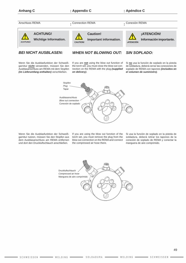
Conexión REMA
Apéndice C
¡ATENCIÓN!
¡ATENCIÓN! Información importante.
SIN SOPLADO:
Si no usa la función de soplado en la pistola de soldadura, deberá cerrar las conexiones de soplado de REMA con tapones (incluidos en el volumen de suministro).
Si usa la función de soplado en la pistola de soldadura, deberá retirar los tapones de la conexión de soplado de REMA y conectar la manguera de aire comprimido.
Connection REMA
Appendix C
CAUTION!
Caution! Important information.
WHEN NOT BLOWING OUT:
If you are not using the blow out function of the torch set, you must close the blow out con-nection on the REMA with the plug (supplied on delivery).
If you are using the blow out function of the torch set, you must remove the plug from the blow out connection on the REMA and connect the compressed air hose there.
Anschluss REMA
Anhang C
Wenn Sie die Ausblasfunktion der Schweiß- garnitur nicht verwenden, müssen Sie den Ausblasanschluss am REMA mit dem Stopfen (im Lieferumfang enthalten) verschließen.
Wenn Sie die Ausblasfunktion der Schweiß- garnitur nutzen, müssen Sie den Stopfen aus dem Ausblasanschluss am REMA entfernen und dort den Druckluftschlauch anschließen.
ACHTUNG!
ACHTUNG! Wichtige Information.
BEI NICHT AUSBLASEN:
S C H W E I S S E N W E L D I N G W E L D I N GS O L D A D U R A S C H W E I S S E N
49
DruckluftschlauchCompressed air hoseManguera de aire comprimido
StopfenPlugTapar
AusblasanschlussBlow out connectionConexión de soplado
:
:
:
:

¡ATENCIÓN!
Si el conectador enchufable del cable del sensor de tobe-ras de gas no se aísla, el operador de la soldadora o de la unidad de control podrá electrocutarse.
Por tanto, deberá aislar bien el conector enchufable del cable del sensor de tobe-ras de gas si no lo va a utilizar.
1. Aísle el conector enchufable del sensor de toberas de gas, por ejemplo con cinta aislante o una manguera en caliente.
2. Enrolle el cable del sensor de toberas de gas alrededor de la interfaz rotativa y ase-gúrelo con cinta aislante.
3. Desplace la carcasa hasta el tope sobre la interfaz rotativa.
Montaje de la interfaz rotativa sin sensor de toberas de gas
Apéndice D
Complete mounting of rotary interface without gas nozzle sensor
CAUTION!
Failure to insulate the con-nector of the gas nozzle sen-sor creates a risk of electric shock for the operator of the welding plant and/or the control unit.
Thoroughly insulate the connector of the gas nozzle sensor cable if it is not being used.
1. Insulate the connector of the gas nozzle sensor, e.g. with electrical tape or shrink tubing.
2. Wrap the gas nozzle sensor cable around the rotary interface and then secure it with electrical tape.
3. Slide the housing up to the stop over the rotary interface.
Appendix D
Drehmedium ohne Gasdüsensensor fertig montieren
ACHTUNG!
Wird der Steckverbinder des Gasdüsensensorkabels nicht isoliert, droht ein elektrischer Schlag für den Bediener der Schweißanlage und/oder die Steuereinheit.
Isolieren Sie gründlich den Steckverbinder des Gasdüsensensorkabels, wenn die-ses nicht verwendet wird.
1. Isolieren Sie den Steckverbinder des Gasdüsensensors, z.B. mit Isolierklebeband oder Schrumpfschlauch.
2. Wickeln Sie das Gasdüsensensorkabel um das Drehmedium und sichern es anschlie-ßend mit einem Isolierband.
3. Schieben Sie das Gehäuse bis zum An-schlag über das Drehmedium.
Anhang D
S C H W E I S S E N W E L D I N G W E L D I N GS O L D A D U R A S C H W E I S S E N
50
:
:
:
:

Apéndice D
Montaje de la interfaz rotativa sin sensor de toberas de gas
1. Coloque la protección de goma sobre la interfaz rotativa.
INFO
¡Tenga en cuenta las indicaciones de montaje del robot Motoman-Yaskawa con protección frente a pandeo en el sexto eje del eje en el anexo A!
Appendix D
Complete mounting of rotary interface without gas nozzle sensor
1. Place the dust boot on the rotary interface.
INFO
P l e a s e n o t e t h e m o u n t i n g instructions for Motoman-Yaskawa robots with bend protection on the 6th axis in Appendix A!
Anhang D
Drehmedium ohne Gasdüsensensor fertig montieren
4. Setzen Sie die Manschette auf das Drehmedium auf.
INFO
B e a c h t e n S i e b i t t e d i e M o n t a g e h i n w e i s e f ü r M o t o -m a n - Y a s k a w a - R o b o t e r m i t Knickschutz an der 6. Achse im Anhang A !
S C H W E I S S E N W E L D I N G W E L D I N GS O L D A D U R A S C H W E I S S E N
51
:
:
:
:

Apéndice E
Interfaz rotativa con freno de hilo integrado
Ventajas del freno de hilo integrado en la interfaz rotativa:
● El freno de hilo garantiza un Stickout/TCP constante.
● A través de ciclos de freno de libre progra-mación, el hilo siempre permanecerá en la misma posición exacta.
● El Stickout/TCP se mantendrá en todo el proceso de medición.
● El freno de hilo garantiza un stickout abso-lutamente constante, incluso en caso de diferentes diámetros de hilo.
Si se activa el freno al final del proceso desoldadura, el hilo no se retraerá.
¡ADVERTENCIA!
En las interfaces rotativas con freno de hilo DIX RET 341 F(S) (WB 1) deberá tener en cuenta que las espirales de guía de hilo se deben intro-ducir en dos piezas.
Appendix E
Rotary interface with integrated wire brake
Advantages of the integrated wire brake in the rotary interface:
● The wire brake guarantees a constant stickout/TCP.
● The wire brake always keeps the wire in exactly the same position thanks to freely programmable brake cycles.
● The stickout/TCP is maintained over the entire measurement process.
● The wire brake guarantees an absolutely constant stickout, even with different wire diameters.
If the wire brake is activated after completion of the welding process, the wire does not pull back.
WARNING!
Please note for the rotary interfaces with DIX RET 341 F(S) (WB 1) wire brake that the liner needs to be inserted in two parts
Drehmedium mit integrierter Drahtbremse
Anhang E
Vorteile der integrierten Drahtbremse im Drehmedium:
● Die Drahtbremse garantiert einen konstanten Stickout/TCP.
● Durch frei programmierbare Bremszyklen hält die Drahtbremse den Draht immer exakt in der gleichen Position.
● Der Stickout/TCP wird bei dem gesamten Messprozess gehalten.
● Die Drahtbremse garantiert einen absolut konstanten Stickout, auch bei unterschied-lichen Drahtdurchmessern.
Wird die Drahtbremse nach Ende des Schweißprozesses aktiviert zieht sich der Draht nicht zurück.
WARNUNG!
Beachten Sie bitte bei den Drehmedien mit Drahtbremse DIX RET 341 F(S) (WB 1), dass die Drahtführungsspirale in zwei Teilen eingeführt wer-den muß
S C H W E I S S E N W E L D I N G W E L D I N GS O L D A D U R A S C H W E I S S E N
52
:
:
:
:

2. Coloque la sujeción de la pistola en la pistola y guíe la manguera neumática del frenodehiloatravésdelorificioprevisto.
3. Atornille la sujeción de la pistola con los dos tornillos hexagonales suministrados (M4 x 12 mm) con una llave de hexágono interior S W 2,5, con 3 Nm.
Montaje de la pistola
Interfaz rotativa con freno de hilo integrado
1. Inserte la pistola por el cuarto y el quinto eje del brazo del robot hasta el sexto.
¡ATENCIÓN!
¡Tenga en cuenta las indica-ciones de montaje del robot Motoman-Yaskawa con protec-ción frente a pandeo en el sexto eje del anexo A (1.)!
Apéndice E
2. Placethetorchsetfixtureonthetorchset,pull the pneumatic hose of the wire brake through the hole provided.
3. Tightenthetorchsetfixtureto3Nmwiththetwoflatheadscrews(M4x12mm)suppliedusing a 2.5 mm hexagon key.
Mounting the torch set
Rotary interface with integrated wire brake
1. Guide the torch set through the 4th and 5th axis of the robot arm up to the 6th.
CAUTION!
Please note the mounting instructions for Motoman-Yaskawa robots with bend protection on the 6th axis in Appendix A (1.)
Appendix E
Montage Schweißgarnitur
Drehmedium mit integrierter Drahtbremse
1. Führen Sie die Schweißgarnitur durch die 4.und 5. Achse des Roboterarms bis durch die 6.
2. Setzen Sie die Schweißgarniturbefestigung auf die Schweißgarnitur, ziehen sie den Pneumatikschlauch der Drahtbremse durch die vorgesehene Bohrung.
3. Schrauben Sie die Schweißgarnitur-befestigung mit den zwei mitgelieferten Senkschrauben (M4 x 12 mm) mit einem Innensechskantschlüssel SW 2,5, mit 3 Nm, fest.
ACHTUNG!
Beachten Sie bi t te die Montagehinweise für Moto-man-Yaskawa-Roboter mit Knickschutz an der 6. Achse im Anhang A (1.)
Anhang E
S C H W E I S S E N W E L D I N G W E L D I N GS O L D A D U R A S C H W E I S S E N
53
Senkschraube CountersunkTornillo avellanado 2 x M4 x 12 mm
PneumatikschlauchPneumatic hoseManguera neumática
= 3 Nm
:
:
:
:

Montaje de la pistola
Interfaz rotativa con freno de hilo integrado
4. Desplace la pistola con la sujeción hasta el tope de la brida adaptadora en el sexto eje del brazo del robot. Alinee la sujeción de la pistola en el pin de posición.
5. Atornille la sujeción de la pistola con los dos tornillos de hexágono interior suministrados (M5 x 8 mm) con una llave de hexágono interior SW 4, con un par de 3 Nm.
Apéndice E
Mounting the torch set
Rotary interface with integrated wire brake
4. Slide the torch set with the torch set fixture against the stop on the adap-ter flange into the 6th axis of the robotarm. Align the torch set fixture on the position pin at the same time.
5. Tightenthetorchsetfixtureto3Nmwiththetwo hexagon socket screws (M5 x 8 mm) supplied using a 4 mm hexagon key.
Appendix E
Montage Schweißgarnitur
Drehmedium mit integrierter Drahtbremse
4. Schieben Sie die Schweißgarnitur mit der Schweißgarniturbefestigung bis zum Anschlag am Adapterflansch in die 6. Achse vom Roboterarm. Richten Sie dabei die Schweißgarniturbefestigung am Posi- tionspin aus.
5. Schrauben Sie die Schweißgarnitur-befestigung mit den zwei mitgelieferten Innensechskantschrauben (M5 x 8 mm) mit einem Innensechskantschlüssel SW 4, mit 3 Nm, fest
Anhang E
S C H W E I S S E N W E L D I N G W E L D I N GS O L D A D U R A S C H W E I S S E N
54
Gewindestifte für Sechskantmuttern zur Befestigung des DrehmediumsThread pins for Allen nuts for mounting the rotary mediumTornillos prisioneros para tuercas Allen para el montaje del soporte giratorio
PositionspinPosition pinPin de posición
= 3 Nm
InnensechskantschraubeAllen socket screwTornillo de cabeza Allen2 x M5 x 8 mm
:
:
:
:

Espiral de guía de hilo
Interfaz rotativa con freno de hilo integrado
¡ATENCIÓN!
La pistola debe estar correc-tamente montada para que la espiral de guía de hilo tenga la longitud adecuada.
¡Compruebe que la pistola esté correc-tamente montada!
¡ATENCIÓN!
Una espiral de guía de hilo con un diámetro interior demasiado pequeño impide la extracción del hilo. Un diámetro interior demasiado grande puede tener una influ-encia negativa en la calidad de la costura de soldadura.
Controle el diámetro interior de la espi-ral de guía de hilo y cámbiela en caso necesario por una espiral de guía de hilo adecuada.Consulte las listas de piezas de des-gaste y repuesto para seleccionar la espiral de guía de hilo adecuada.
¡ATENCIÓN!
Las rebabas afiladas en la punta de la espiral de guía de hilo pueden dañar el con-ducto de transporte de hilo.
Asegúrese de introducir las espirales de guía de hilo cortadas por DINSE por el lado desbarbado en la pistola.Asegúrese de que en las espirales de guía de hilo que corte usted mismo se desbarbe primero el extremo y se intro-duzca la espiral de guía de hilo con el lado desbarbado en la pistola.
INFO
¡Deberá controlar la junta tórica en la conexión de la pistola en cada cambio de la espiral de guía de hilo, sustituirla y engrasarla con vaselina técnica!
Apéndice E
Liner
Rotary interface with integrated wire brake
CAUTION!
The torch set must be cor-rectly mounted for the liner to have the right length.
Check that the torch set has been moun-ted correctly!
CAUTION!
A liner with too small an inside diameter interferes with the wire feeding. Too large an inside diameter may have a negative effect on the weld quality.
Check the inside diameter of the liner and replace it with a matching liner if necessary.Refer to the spare and wear parts list to select the matching liners.
CAUTION!
Sharp burs at the tip of the liner may destroy the wire feed hose.
Ensure that you insert liners cut to length by DINSE into the torch set with the groundoffsidefirst.Ensure with liners you have cut to size yourselfthatyoufirstdeburoneendandthen insert the liner with the deburred side into the torch set.
INFO
Each time you replace the liner the O-rings on the torch set connection must be checked, replaced and gre-ased with technical Vaseline!
Appendix E
Drahtführungsspirale
Drehmedium mit integrierter Drahtbremse
ACHTUNG!
Die Schweißgarnitur muss korrekt montiert sein, damit die Drahtführungsspirale die richtige Länge hat.
Prüfen Sie, ob die Schweißgarnitur richtig montiert ist!
ACHTUNG!
Eine Drahtführungsspirale mit zu kleinem Innendurch-messer behindert die Draht-förderung. Ein zu großer Innendurchmesser kann negativen Einfluss auf die Schweißnahtqualität haben.
Kontrollieren Sie den Innendurchmesser der Drahtführungsspirale und tau-schen diese gegebenenfalls gegen eine passende Drahtführungsspirale aus.Schauen Sie in die Ersatz- und Verschleißteilelisten, um die passen-den Drahtführungsspirale auszuwählen.
ACHTUNG!
Scharfe Grate an der Spitze der Drahtführungsspirale können den Drahtförder-schlauch zerstören.
Achten Sie darauf, dass Sie bei von DINSE abgelängte Drahtführungsspiralen, diese mit der abgeschliffenen Seite in die Schweißgarnitur einführen.Achten Sie darauf, dass Sie bei selbst zugeschnittenen Drahtführungsspiralen, ein Ende erst entgraten und die Drahtführungsspirale mit der entgrateten Seite in die Schweißgarnitur einführen.
INFO
A c h t e n S i e d a r a u f , d a s s S ie be i j edem Wechse l de r Drahtführungsspirale die O-Ringe am Schweißgarnituranschluss kon-trollieren, erneuern und mit techni-scher Vaseline einfetten!
Anhang E
S C H W E I S S E N W E L D I N G W E L D I N GS O L D A D U R A S C H W E I S S E N
55
:
:
:
:

Espiral de guía de hilo
Interfaz rotativa con freno de hilo integrado
6. Desplace la espiral de guía de hilo a través de la sujeción de la pistola de soldadura en la pistola de soldadura hasta el tope en el perno de conexión.
¡ATENCIÓN!
Al cortar las rebabas restan-tes pueden obstaculizar la guía del hilo.
Controle, tras el corte, las rebabas del extremo de la espiral de guía de hilo y elimínelas en caso necesario.Tenga en cuenta las indicaciones de corte de espirales de guía de hilo del Anexo F.
7. Corte la espiral de guía de hilo aprox. 2 - 4 mm antes del extremo en el conducto de transporte de hilo.
Apéndice E
Liner
Rotary interface with integrated wire brake
6. Slidethelinerthroughthetorchsetfixtureinto the torch set against the stop in the connecting mandrel.
CAUTION!
Burs created during cutting may interfere with wire fee-ding.
Check the end of the liner for burs after cutting and remove any burs if present.Observe the notes on cutting liners in Appendix F.
7. Cut off the liner approx. 2 - 4 mm before the end on the green conduit hose.
Appendix E
Drahtführungsspirale
Drehmedium mit integrierter Drahtbremse
6. Schieben Sie die Drahtführungsspirale durch die Schweißgarniturbefestigung in die Schweißgarnitur bis zum Anschlag im Anschlussdorn.
ACHTUNG!
Beim Schneiden entstan-dene Grate können die Drahtförderung behindern.
Kontrollieren Sie, nach dem Schneiden, das Ende der Drahtführungsspirale auf Grate und entfernen Sie diese gegebe-nenfalls.
Beachten Sie die Hinweise zum Schneiden von Drahtführungsspiralen im Anhang F.
7. Schneiden Sie die Drahtführungsspirale ca. 2 - 4 mm vor dem Ende am grünen Drahtförderschlauch ab.
Anhang E
S C H W E I S S E N W E L D I N G W E L D I N GS O L D A D U R A S C H W E I S S E N
56
Anschlag AnschlussdornStop connecting mandrelMandril de conexión
SchweißgarniturbefestigungTorch set fixingPistolas de soldadura fijación
:
:
:
:

Preparativos para el montaje de la interfaz giratoria.
1. Engrase todas las juntas tóricas de la pistola con la vaselina técnica suministrada.
2. Guíe la manguera neumática del freno de hilodesdeatrásatravésdelorificiolateralde la interfaz rotativa.
Interfaz rotativa con freno de hilo integrado
Apéndice E
Rotary interface with integrated wire brake
Preparations for mounting the rotary inter-face.
1. Grease each individual O-ring of the torch set all the way around with the technical Vaseline supplied.
2. Pull the pneumatic hose of the wire brake through the lateral opening of the rotary interface.
Appendix E
Drehmedium mit integrierter Drahtbremse
Vorbereitungen für die Montage des Drehmediums.
1. Fetten Sie jeden einzelnen O-Ring der Schweißgarnitur ringsum mit der mitgelie-ferten technischen Vaseline ein.
2. Ziehen Sie den Pneumatikschlauch der Drahtbremse durch die seitliche Öffnung des Drehmediums.
Anhang E
S C H W E I S S E N W E L D I N G W E L D I N GS O L D A D U R A S C H W E I S S E N
57
PneumatikschlauchPneumatic hoseManguera neumática
:
:
:
:

Interfaz rotativa con freno de hilo integrado
¡ATENCIÓN!
En caso de una colocación angulada o inclinada de la interfaz rotativa, las juntas tóricas podrían dañarse en la conexión de la pistola. En este caso, las conexiones de gas no estarán estancas, por lo que es posible que salga agua en la interfaz rotativa de forma incontrolada.
Coloque la interfaz rotatoria con cuidado y de forma recta en la conexión de la pistola.Nunca desplace la interfaz rotativa con excesiva fuerza en la conexión de la pistola.
1. Coloque la interfaz rotativa en posición recta en la pistola y desplácela con cuidado hasta el tope de la sujeción de la pistola.
2. Atornille las tuercas hexagonales y las tres arandelas con la mano en los tor-nillos prisioneros.
Apéndice E
CAUTION!
Positioning the rotary inter-face at an angle or crookedly may damage the O-rings on the torch set connection. The gas connections will then leak and gas escape in the rotary interface.
Place the rotary interface carefully on the torch set connection and ensure it is straight.Never use force when sliding the rotary interface onto the torch set connection.
1. Place the rotary interface straight on the torch set connection and then push the rotary interface carefully against the stoponthetorchsetfixture.
2. Screw the three hexagon nuts and three washers supplied onto the screw pins by hand.
Rotary interface with integrated wire brake
Appendix E
Drehmedium mit integrierter Drahtbremse
ACHTUNG!
Ein schiefes oder verkantetes Aufsetzen des Drehmediums k a n n d i e O - R i n g e a m Schweißgarnituranschluss beschädigen. Die Gasan-schlüsse sind dann undicht, so dass Gas unkontrolliert im Drehmedium austritt.
Setzen Sie das Drehmedium vor-s i c h t i g u n d g e r a d e a u f d e n Schweißgarnituranschluss auf.Schieben Sie das Drehmedium n i e m a l s m i t G e w a l t a u f d e n Schweißgarnituranschluss.
1. Setzen Sie das Drehmedium gerade auf den Schweißgarnituranschluss und schieben Sie dann das Drehmedium vorsichtig bis zum Anschlag an die Schweißgarniturbe-festigung.
2. Schrauben Sie die drei mitgelieferten Sechs- kantmuttern und drei Unterlegscheiben, mit der Hand auf die Gewindestifte.
Anhang E
S C H W E I S S E N W E L D I N G W E L D I N GS O L D A D U R A S C H W E I S S E N
58
Sechskantmuttern und UnterlegscheibenAllen nuts and and washersTuercas Allen y arandelas3 x M5
Gewindestifte für SechskantmutternThread pins for Allen nuts Tornillos prisioneros para tuercas Allen3 x M5
:
:
:
:

Interfaz rotativa con freno de hilo integrado
3. Atornille las tuercas hexagonales con una llave de tornillos SW8 y con un par de 4 Nm.
Apéndice E
Rotary interface with integrated wire brake
3. Tighten the hexagon nuts to 4 Nm with an 8 mm wrench.
Appendix E
Drehmedium mit integrierter Drahtbremse
3. Schrauben Sie die Sechskantmuttern mit einem Schraubenschlüssel SW 8, mit 3 Nm fest.
Anhang E
S C H W E I S S E N W E L D I N G W E L D I N GS O L D A D U R A S C H W E I S S E N
59
= 3 Nm
:
:
:
:
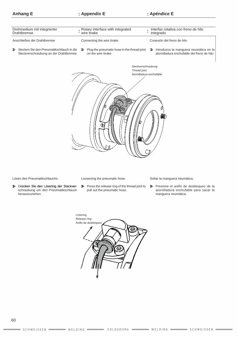
Interfaz rotativa con freno de hilo integrado
Conexión del freno de hilo
Apéndice E
Introduzca la manguera neumática en la atornilladura enchufable del freno de hilo
Soltar la manguera neumática:
Presione el anillo de desbloqueo de la atornilladura enchufable para sacar la manguera neumática.
Rotary interface with integrated wire brake
Connecting the wire brake
Appendix E
Plug the pneumatic hose in the thread joint on the wire brake
Loosening the pneumatic hose:
Press the release ring of the thread joint to pull out the pneumatic hose.
Drehmedium mit integrierter Drahtbremse
Anschließen der Drahtbremse
Stecken Sie den Pneumatikschlauch in die Steckverschraubung an der Drahtbremse
Lösen des Pneumatikschlauchs:
Drücken Sie den Lösering der Steckver-rücken Sie den Lösering der Steckver-schraubung um den Pneumatikschlauch herauszuziehen.
Anhang E
S C H W E I S S E N W E L D I N G W E L D I N GS O L D A D U R A S C H W E I S S E N
60
SteckverschraubungThread jointAtornilladura enchufable
LöseringRelease ringAnillo de desbloqueo
:
:
:
:
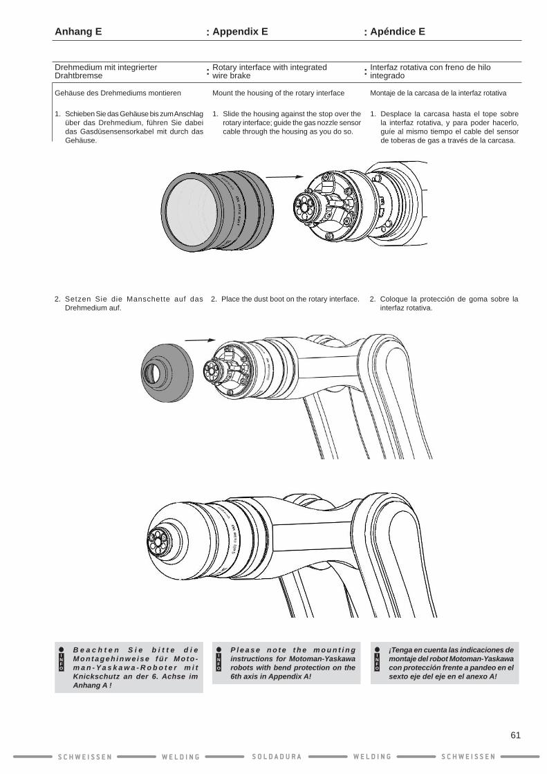
1. Desplace la carcasa hasta el tope sobre la interfaz rotativa, y para poder hacerlo, guíe al mismo tiempo el cable del sensor de toberas de gas a través de la carcasa.
Interfaz rotativa con freno de hilo integrado
Montaje de la carcasa de la interfaz rotativa
Apéndice E
2. Coloque la protección de goma sobre la interfaz rotativa.
INFO
¡Tenga en cuenta las indicaciones de montaje del robot Motoman-Yaskawa con protección frente a pandeo en el sexto eje del eje en el anexo A!
1. Slide the housing against the stop over the rotary interface; guide the gas nozzle sensor cable through the housing as you do so.
Rotary interface with integrated wire brake
Mount the housing of the rotary interface
Appendix E
2. Place the dust boot on the rotary interface.
INFO
P l e a s e n o t e t h e m o u n t i n g instructions for Motoman-Yaskawa robots with bend protection on the 6th axis in Appendix A!
1. Schieben Sie das Gehäuse bis zum Anschlag über das Drehmedium, führen Sie dabei das Gasdüsensensorkabel mit durch das Gehäuse.
Drehmedium mit integrierter Drahtbremse
Gehäuse des Drehmediums montieren
Anhang E
2. Setzen Sie die Manschette auf das Drehmedium auf.
INFO
B e a c h t e n S i e b i t t e d i e M o n t a g e h i n w e i s e f ü r M o t o -m a n - Y a s k a w a - R o b o t e r m i t Knickschutz an der 6. Achse im Anhang A !
S C H W E I S S E N W E L D I N G W E L D I N GS O L D A D U R A S C H W E I S S E N
61
:
:
:
:

Interfaz rotativa con freno de hilo integrado
Montaje del cabezal de pistola
1. Atornille la tubuladora DIX MES 300/500 manualmente en el cabezal de pistola.
2. Apriete la tubuladora con una llave de tor-nillos SW 8 (manualmente).
3. Coloque el cabezal de pistola en las uni-dades de conexión de la interfaz rotativa y atornille la tuerca de unión manualmente.
¡ADVERTENCIA!
Si la llave para tuercas ranur-adas DIX SLAT 4 se fija al revés pueden provocarse lesiones en las manos o es posible que se dañe la llave para tuercas ranuradas o la tuerca de unión.
Asegúrese de que la llave para tuercas ranuradas DIX SLAT 4 esté colocada correctamente sobre la tuerca de unión.
4. Apriete bien la tuerca de unión con la llave para tuercas ranuradas DIX SLAT 4 para garantizar el asiento correcto del cabezal de pistola.
Apéndice E
1. Screw the DIX MES 300/500 connecting piece by hand into the torch head.
2. Tighten the connecting piece (hand-tight) with an 8 mm wrench.
3. Place the torch head on the connection body of the rotary interface and tighten the cap nut by hand.
WARNING!
Incorrect positioning of the DIX SLAT 4 hook spanner may cause hand injuries and/or damage the hook spanner or the cap nut!
Ensure that the DIX SLAT 4 sits correctly on the cap nut.
4. UsetheDIXSLAT4hookspannertofirmlytighten the cap nut to ensure secure seating of the torch head.
Rotary interface with integrated wire brake
Mounting the torch head
Appendix E
Drehmedium mit integrierter Drahtbremse
Montage Pistolenkopf
1. Schrauben Sie den Stutzen DIX MES 300/500 mit der Hand in den Pistolenkopf ein.
2. Ziehen Sie den Stutzen mit einem Schrau-benschlüssel SW 8 fest (Handfest).
3. Setzen Sie den Pistolenkopf auf den Anschlusskörper des Drehmediums und schrauben Sie die Überwurfmutter mit der Hand fest.
WARNUNG!
Ein verkehrtes Ansetzten des Hakenschlüssel DIX SLAT 4 kann zu Handverletzungen f ü h r e n u n d / o d e r d e n Hakenschlüssel oder die Überwurfmutter beschädi-gen !
Achten sie darauf, dass der Haken-schlüssel DIX SLAT 4 richtig auf der Überwurfmutter sitzt.
4. Ziehen Sie mit dem Hakenschlüssel DIX SLAT 4 die Überwurfmutter richtig fest, um einen sicheren Sitz des Pistolenkopfes zu gewährleisten.
Anhang E
S C H W E I S S E N W E L D I N G W E L D I N GS O L D A D U R A S C H W E I S S E N
62
Stutzen DIX MES 300/500Connecting piece DIX MES 300/500Tubuladora DIX MES 300/500 = Handfest
= Hand-tight= manualmente
:
:
:
:
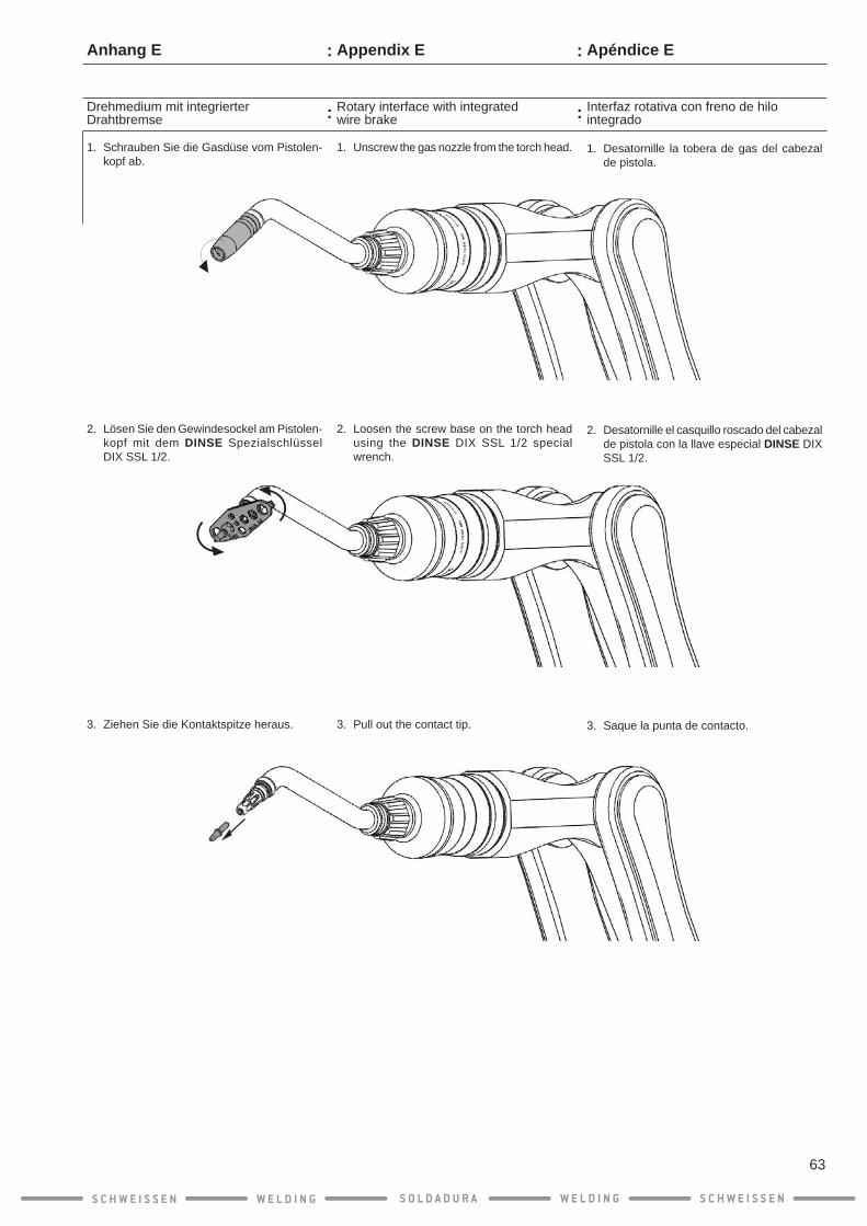
Interfaz rotativa con freno de hilo integrado
1. Desatornille la tobera de gas del cabezal de pistola.
2. Desatornille el casquillo roscado del cabezal de pistola con la llave especial DINSE DIX SSL 1/2.
3. Saque la punta de contacto.
Apéndice E
Rotary interface with integrated wire brake
1. Unscrew the gas nozzle from the torch head.
2. Loosen the screw base on the torch head using the DINSE DIX SSL 1/2 special wrench.
3. Pull out the contact tip.
Appendix E
Drehmedium mit integrierter Drahtbremse
1. Schrauben Sie die Gasdüse vom Pistolen-kopf ab.
2. Lösen Sie den Gewindesockel am Pistolen-kopf mit dem DINSE Spezialschlüssel DIX SSL 1/2.
3. Ziehen Sie die Kontaktspitze heraus.
Anhang E
S C H W E I S S E N W E L D I N G W E L D I N GS O L D A D U R A S C H W E I S S E N
63
:
:
:
:

Interfaz rotativa con freno de hilo integrado
¡ADVERTENCIA!
Una espiral de guía de hilo con un diámetro interior demasiado pequeño impide la extracción del hilo. Un diáme-tro interior demasiado grande puede tener una influencia negativa en la calidad de la costura de soldadura.
Controle el diámetro interior de la espi-ral de guía de hilo y cámbiela en caso necesario por una espiral de guía de hilo adecuada.Consulte las listas de piezas de des-gaste y repuesto para seleccionar la espiral de guía de hilo adecuada.
4. Inserte la espiral de guía de hilo en el cabezal de pistola y desplace la espiral de guía de hilo hasta el tope en el devanador de hilo.
5. Retire ahora la espiral de guía de hilo aprox. 10 mm.
Apéndice E
Rotary interface with integrated wire brake
WARNING!
A liner with too small an inside diameter interferes with the wire feeding. Too large an inside diameter may have a negative effect on the weld quality.
Check the inside diameter of the liner and replace it with an appropriate liner if necessary.Refer to the spare and wear parts list to select the matching liners.
4. Insert the l iner into the torch head and slide the liner against the stop in the wire feeder.
5. Now pull back the liner approx. 10 mm.
Appendix E
Drehmedium mit integrierter Drahtbremse
WARNUNG!
Eine Drahtführungsspirale mit zu kleinem Innendurch-messer behindert die Draht-förderung. Ein zu großer Innendurchmesser kann negativen Einfluss auf die Schweißnahtqualität haben.
Kontrollieren Sie den Innendurchmesser der Drahtführungsspirale und tau-schen diese gegebenenfalls gegen eine passende Drahtführungsspirale aus.Schauen Sie in die Ersatz- und Verschleißteilelisten, um die passen-den Drahtführungsspirale auszuwählen.
4. Führen Sie die Drahtführungsspirale in den Pistolenkopf ein und schieben Sie die Drahtführungsspirale bis zum Anschlag im Drahtvorschub.
5. Ziehen Sie jetzt die Drahtführungsspirale ca. 10 mm zurück.
Anhang E
S C H W E I S S E N W E L D I N G W E L D I N GS O L D A D U R A S C H W E I S S E N
64
:
:
:
:
zurückziehenca. 10 mm pull back retrasar
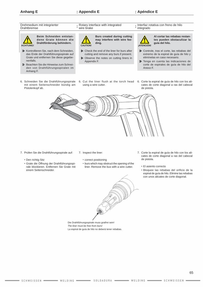
¡ATENCIÓN!
Al cortar las rebabas restan-tes pueden obstaculizar la guía del hilo.
Controle, tras el corte, las rebabas del extremo de la espiral de guía de hilo y elimínelas en caso necesario.Tenga en cuenta las indicaciones de corte de espirales de guía de hilo del Anexo F.
6. Corte la espiral de guía de hilo con los ali-cates de corte diagonal a ras del cabezal de pistola.
7. Corte la espiral de guía de hilo con los ali-cates de corte diagonal a ras del cabezal de pistola.
•El asiento correcto•Bloquee las rebabas del orificio de la
espiral de guía de hilo. Elimine las rebabas con unos alicates de corte diagonal.
Interfaz rotativa con freno de hilo integrado
Apéndice E
CAUTION!
Burs created during cutting may interfere with wire fee-ding.
Check the end of the liner for burs after cutting and remove any burs if present.Observe the notes on cutting liners in Appendix F.
6. Cut the liner flush at the torch head using a wire cutter.
7. Inspect the liner:
•correct positioning•burs which may obstruct the opening of the
liner. Remove the bus with a wire cutter.
Rotary interface with integrated wire brake
Appendix E
ACHTUNG!
Beim Schneiden entstan-dene Grate können die Drahtförderung behindern.
Kontrollieren Sie, nach dem Schneiden, das Ende der Drahtführungsspirale auf Grate und entfernen Sie diese gegebe-nenfalls.Beachten Sie die Hinweise zum Schnei-den von Drahtführungsspiralen im Anhang F.
6. Schneiden Sie die Drahtführungsspirale mit einem Seitenschneider bündig am Pistolenkopf ab.
7. Prüfen Sie die Drahtführungsspirale auf:
•Den richtig Sitz•Grate die Öffnung der Drahtführungsspi-
rale blockieren. Entfernen Sie Grate mit einem Seitenschneider.
Drehmedium mit integrierter Drahtbremse
Anhang E
S C H W E I S S E N W E L D I N G W E L D I N GS O L D A D U R A S C H W E I S S E N
65
:
:
:
:
Die Drahtführungsspirale muss gratfrei sein!The liner must be free from burs!La espiral de guía de hilo no deberá tener rebabas.
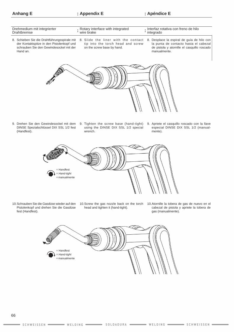
8. Desplace la espiral de guía de hilo con la punta de contacto hasta el cabezal de pistola y atornille el casquillo roscado manualmente.
9. Apriete el casquillo roscado con la llave especial DINSE DIX SSL 1/2 (manual-mente).
10. Atornille la tobera de gas de nuevo en el cabezal de pistola y apriete la tobera de gas (manualmente).
Interfaz rotativa con freno de hilo integrado
Apéndice E
8. S l i de the l i ne r w i t h t he con tac t t ip into the torch head and screw on the screw base by hand.
9. Tighten the screw base (hand-tight) using the DINSE DIX SSL 1/2 special wrench.
10. Screw the gas nozzle back on the torch head and tighten it (hand-tight).
Rotary interface with integrated wire brake
Appendix E
8. Schieben Sie die Drahtführungsspirale mit der Kontaktspitze in den Pistolenkopf und schrauben Sie den Gewindesockel mit der Hand an.
9. Drehen Sie den Gewindesockel mit dem DINSE Spezialschlüssel DIX SSL 1/2 fest (Handfest).
10. Schrauben Sie die Gasdüse wieder auf den Pistolenkopf und drehen Sie die Gasdüse fest (Handfest).
Drehmedium mit integrierter Drahtbremse
Anhang E
S C H W E I S S E N W E L D I N G W E L D I N GS O L D A D U R A S C H W E I S S E N
66
:
:
:
:
= Handfest= Hand-tight= manualmente
= Handfest= Hand-tight= manualmente

Interfaz rotativa con freno de hilo integrado
En el enchufe compacto de la pistola hay una manguera neumática (negra, ø 4 mm) para el freno de hilo.
1. Conecte la manguera neumática.
Apéndice E
Comprobación de recorridos
INFO
Con el sistema de soldadura DINSE ECO.torch se pueden realizar todos los recorridos del robot. La girabilidad ilimitada de la interfaz rotativa ofrece una excelente accesibilidad de los componentes.La extrema capacidad de movimiento de la pistola permite extender y doblar de cualquier forma el brazo del robot.
Compruebe si el robot se puede des-plazar correctamente hacia la posición deseada y si se puede girar el cabezal de pistola correctamente.
Realice por su propia seguridad un control del peso y de la palanca.
INFO
Asegúrese de que cuando ABB Kemppi alimentación de alambre que sustituya la guía de cable antes de conectarlo al pin de alimentación!(véase el Apéndice F)
Rotary interface with integrated wire brake
The pneumatic hose (black, dia. 4 mm) for the wire brake is located on the plug of the set.
1. Connect the pneumatic hose.
Appendix E
Check travel
INFO
Travel of the robot in any direction is possible with the DINSE ECO.torch welding system. The rotation capability of the rotary interface provides excellent component access.Because of its extreme flexibility, the torch set follows any bending or exten-sion of the robot arm.
Check that the robot can t ra -ve l w i thout fau l t to any des i -red posit ion and that the torch head rotates without problem.
For your own safety, perform a check of the weight and lever relationships.
INFO
If you need ABB-Kemppi-wire feed make sure, that you replace the wire guide before connect the power pin set! (see Appendix F)
Drehmedium mit integrierter Drahtbremse
Am Kompaktstecker der Garnitur befindet sich der Pneumatikschlauch (schwarz, ø 4 mm) für die Drahtbremse.
1. Schließen Sie den Pneumatikschlauch an.
Anhang E
Verfahrwege prüfen
INFO
M i t d e m D I N S E E C O . t o r c h Schweißsystem sind alle Verfahrwege des Roboters möglich. Die Drehbarkeit des Drehmediums sorgt für eine sehr gute Bauteil-Zugänglichkeit. Die Schweißgarnitur macht durch ihre extreme Beweglichkeit jede Beugung ode r S t reckung des Roboterarms mit.
Prüfen Sie ob der Roboter fehlerfrei in jede beliebige Position gefahren werden kann und ob sich der Pistolen kopf einwandfrei dreht.
Führen Sie zu Ihrer eigenen Sicherheit eine Kontrolle der Gewichts- und Hebelverhältnisse durch.
INFO
Achten Sie bei ABB-Kemppi-Draht-vorschüben darauf, das Sie die Drahtführung austauschen, bevor Sie die Power-Pin-Garnitur anschließen! (siehe hierzu Anhang F)
S C H W E I S S E N W E L D I N G W E L D I N GS O L D A D U R A S C H W E I S S E N
67
KompacktsteckerPlugEnchufe compacto
:
:
:
:
Pneumatikschlauch (schwarz)Pneumatic hose (black)Manguera neumática (negra)
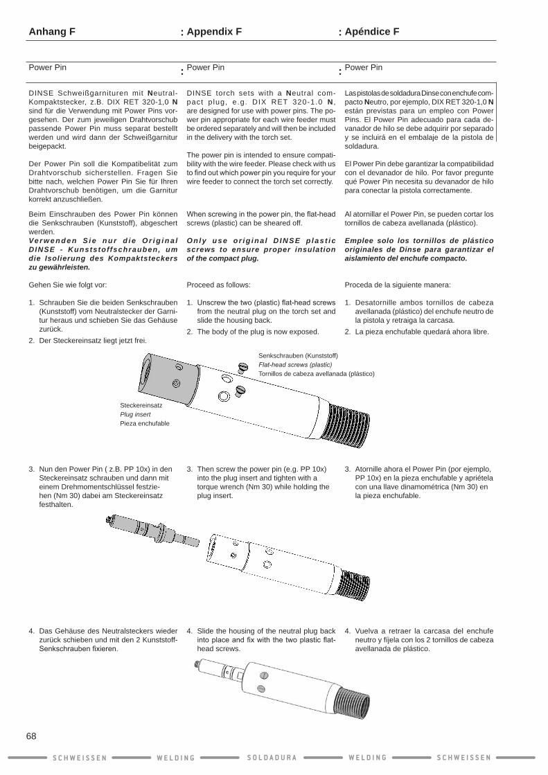
Power Pin
Apéndice F
4. Vuelva a retraer la carcasa del enchufe neutro y fíjela con los 2 tornillos de cabeza avellanada de plástico.
3. Atornille ahora el Power Pin (por ejemplo, PP 10x) en la pieza enchufable y apriétela con una llave dinamométrica (Nm 30) en la pieza enchufable.
Las pistolas de soldadura Dinse con enchufe com-pacto Neutro, por ejemplo, DIX RET 320-1,0 N están previstas para un empleo con Power Pins. El Power Pin adecuado para cada de-vanador de hilo se debe adquirir por separado y se incluirá en el embalaje de la pistola de soldadura.
El Power Pin debe garantizar la compatibilidad con el devanador de hilo. Por favor pregunte qué Power Pin necesita su devanador de hilo para conectar la pistola correctamente.
Al atornillar el Power Pin, se pueden cortar los tornillos de cabeza avellanada (plástico).
Emplee solo los tornillos de plástico originales de Dinse para garantizar el aislamiento del enchufe compacto.
Proceda de la siguiente manera:
1. Desatornille ambos tornillos de cabeza avellanada (plástico) del enchufe neutro de la pistola y retraiga la carcasa.
2. La pieza enchufable quedará ahora libre.
Power Pin
Appendix F
4. Slide the housing of the neutral plug back intoplaceandfixwiththetwoplasticflat-head screws.
3. Then screw the power pin (e.g. PP 10x) into the plug insert and tighten with a torque wrench (Nm 30) while holding the plug insert.
DINSE torch sets with a Neutral com-pact p lug, e.g. DIX RET 320-1.0 N , are designed for use with power pins. The po-wer pin appropriate for each wire feeder must be ordered separately and will then be included in the delivery with the torch set.
The power pin is intended to ensure compati-bility with the wire feeder. Please check with us tofindoutwhichpowerpinyourequireforyourwire feeder to connect the torch set correctly.
Whenscrewinginthepowerpin,theflat-headscrews (plastic) can be sheared off. Only us e o r ig ina l D IN S E p la s t i c screws to ensure proper insulation of the compact plug.
Proceed as follows:
1. Unscrewthetwo(plastic)flat-headscrewsfrom the neutral plug on the torch set and slide the housing back.
2. The body of the plug is now exposed.
Power Pin
Anhang F
DINSE Schweißgarnituren mit Neutral-Kompaktstecker, z.B. DIX RET 320-1,0 N sind für die Verwendung mit Power Pins vor-gesehen. Der zum jeweiligen Drahtvorschub passende Power Pin muss separat bestellt werden und wird dann der Schweißgarnitur beigepackt.
Der Power Pin soll die Kompatibelität zum Drahtvorschub sicherstellen. Fragen Sie bitte nach, welchen Power Pin Sie für Ihren Drahtvorschub benötigen, um die Garnitur korrekt anzuschließen.
Beim Einschrauben des Power Pin können die Senkschrauben (Kunststoff), abgeschert werden. Ve r w e n d e n S i e n u r d i e O r i g i n a l DINSE - Kunststoffschrauben, um die Isolierung des Kompaktsteckers zu gewährleisten.
Gehen Sie wie folgt vor:
1. Schrauben Sie die beiden Senkschrauben (Kunststoff) vom Neutralstecker der Garni-tur heraus und schieben Sie das Gehäuse zurück.
2. Der Steckereinsatz liegt jetzt frei.
4. Das Gehäuse des Neutralsteckers wieder zurück schieben und mit den 2 Kunststoff-Senkschraubenfixieren.
3. Nun den Power Pin ( z.B. PP 10x) in den Steckereinsatz schrauben und dann mit einem Drehmomentschlüssel festzie-hen (Nm 30) dabei am Steckereinsatz festhalten.
S C H W E I S S E N W E L D I N G W E L D I N GS O L D A D U R A S C H W E I S S E N
68
:
:
:
:
SteckereinsatzPlug insertPieza enchufable
Senkschrauben (Kunststoff)Flat-head screws (plastic)Tornillos de cabeza avellanada (plástico)

Proceda de la siguiente manera:
1. Abra el devanador de hilo.2. Abra el bloque de alojamiento de la pistola.
Devanador de hilo ABB-Kemppi
Apéndice G
Dinse - Power Pin para el devanador de hilo ABB-Kemppi - DT 410
INFO
En el devanador de hilo ABB-Kemppi, asegúrese de cambiar la guía de hilo antes de conectar la pistola DINSE-Power-Pin.
Proceed as follows:
1. Open the wire feeder.2. Openthetorchsetfixtureblock.
ABB-Kemppi-Wire feed
Appendix G
DINSE power pin for ABB-Kemppi - DT 410 wire feeder
INFO
When using ABB-Kemppi wire feeders, make sure that you replace the wire guide before you connect the DINSE power pin torch set!
Gehen Sie wie folgt vor:
1. Öffnen Sie den Drahtvorschub.2. Öffnen Sie den Garnituraufnahmeblock.
ABB-Kemppi-Drahtvorschub
Anhang G
DINSE - Power Pin für ABB-Kemppi - DT 410 Drahtvorschub
INFO
Achten Sie bei ABB-Kemppi-Draht-vorschüben darauf, dass Sie die Drahtführung austauschen, bevor Sie die DINSE Power Pin Garnitur anschließen!
S C H W E I S S E N W E L D I N G W E L D I N GS O L D A D U R A S C H W E I S S E N
69
KEMPPI - DT 410 DrahtvorschubKEMPPI - DT 140 wire feederKEMPPI - DT 410 Devanador de hilo
: :
DINSE - Power Pin
DrahtführungWire guideGuía de hilo
Garnituraufnahmeblock TorchsetfixtureblockBloque de alojamiento
: :

Apéndice G
3. Saque la guía de hilo Kemppi.
5. Introduzca el enchufe neutro de la pistola con el Power Pin hasta el tope en el bloque de alojamiento de la pistola del devanador de hilo.
4. Introduzca la guía de hilo DINSE hasta el tope.
Devanador de hilo ABB-Kemppi
Appendix G
3. Pull out the Kemppi wire guide.
5. Insert the neutral plug of the torch set, with thepowerpinfirst,untilitreachesthestopinthetorchsetfixtureblockofthewirefeed.
4. Insert the DINSE wire guide until it reaches the stop.
ABB-Kemppi-Wire feed
Anhang G
3. Ziehen Sie die Kemppi-Drahtführung heraus.
5. Stecken Sie den Neutralstecker der Gar-nitur, mit dem Power Pin voran, bis zum Anschlag, in den Garnituraufnahmeblock vom Drahtvorschub.
4. Setzen Sie die DINSE - Drahtführung bis zum Anschlag ein.
ABB-Kemppi-Drahtvorschub
S C H W E I S S E N W E L D I N G W E L D I N GS O L D A D U R A S C H W E I S S E N
70
: :
Drahtführung (Kemppi)Wire guide (Kemppi)Guía de hilo (Kemppi)
Drahtführung (DINSE - Power Pin)Wire guide (DINSE power pin)Guía de hilo (DINSE - Power Pin)
: :

Apéndice G
6. Atornille el bloque de alojamiento de la pistola (manualmente).
7. Cierre el devanador de hilo.
Devanador de hilo ABB-Kemppi
Appendix G
6. Screwinthetorchsetfixtureblock(handtight).
7. Close the wire feeder.
ABB-Kemppi-Wire feed
Anhang G
6. Garnituraufnahmeblock zuschrauben (handfest).
7. Drahtvorschub schliessen.
ABB-Kemppi-Drahtvorschub
S C H W E I S S E N W E L D I N G W E L D I N GS O L D A D U R A S C H W E I S S E N
71
: :
: :

1. Coloque los alicates de corte diagonal en la ranura para cortar la espiral de guía de hilo.
2. Controle si hay rebabas interiores en el extremo cortado de la espiral de guía de hilo que puedan obstaculizar el transporte de hilo.
3. Coloque los alicates de corte diagonal en un ángulo aprox. de 45° para cortar las rebabas.
Apéndice H
Corte correcto de la espiral de guía de hilo
Appendix H
Correct cutting of liners
1. Position the wire cutter on the groove to cut off the liner.
2. Check the cut off end of the liner for any burs protruding toward the inside, which may interfere with the wire feeding.
3. Position the wire cutter at an angle of approx. 45° to cut off the bur.
Anhang H
Korrektes Schneiden von Drahtführungsspiralen
1. Setzen Sie den Seitenschneider in der Rille an, um die Drahtführungsspirale ab-zuschneiden.
2. Kontrollieren Sie das abgeschnittene Ende der Drahtführungsspirale auf nach innen ragende Grate, welche die Drahtförderung behindern können.
3. Setzen Sie den Seitenschneider ca. im 45°-Winkel an, um den Grat abzuschneiden.
S C H W E I S S E N W E L D I N G W E L D I N GS O L D A D U R A S C H W E I S S E N
72
Nach innen ragender GratBur protruding toward the inside.Rebaba hacia el interior
: :
: :
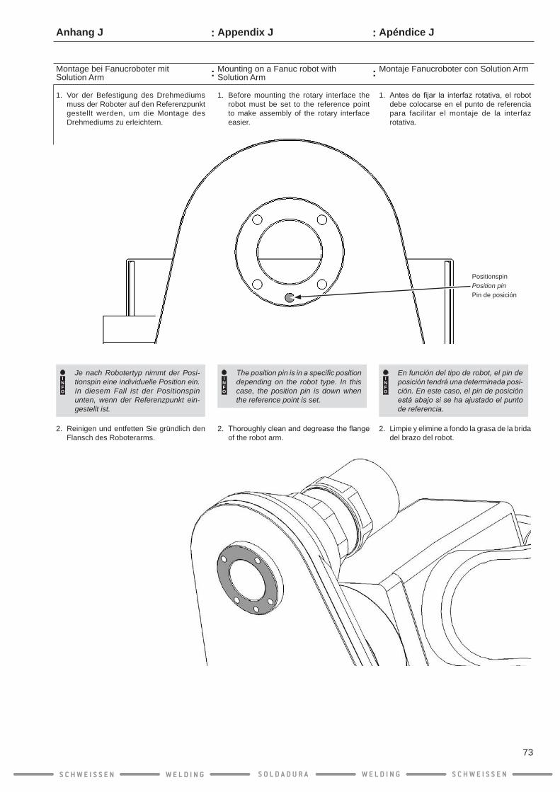
Apéndice J
Montaje Fanucroboter con Solution Arm
1. Antesdefijar la interfaz rotativa,el robotdebe colocarse en el punto de referencia para facilitar el montaje de la interfaz rotativa.
INFO
En función del tipo de robot, el pin de posición tendrá una determinada posi-ción. En este caso, el pin de posición está abajo si se ha ajustado el punto de referencia.
2. Limpie y elimine a fondo la grasa de la brida del brazo del robot.
1. Before mounting the rotary interface the robot must be set to the reference point to make assembly of the rotary interface easier.
INFO
The position pin is in a specific position depending on the robot type. In this case, the position pin is down when the reference point is set.
2. Thoroughlycleananddegreasetheflangeof the robot arm.
Appendix J
Mounting on a Fanuc robot with Solution Arm
1. Vor der Befestigung des Drehmediums muss der Roboter auf den Referenzpunkt gestellt werden, um die Montage des Drehmediums zu erleichtern.
INFO
Je nach Robotertyp nimmt der Posi- tionspin eine individuelle Position ein. In diesem Fall ist der Positionspin unten, wenn der Referenzpunkt ein-gestellt ist.
2. Reinigen und entfetten Sie gründlich den Flansch des Roboterarms.
Anhang J
Montage bei Fanucroboter mit Solution Arm
S C H W E I S S E N W E L D I N G W E L D I N GS O L D A D U R A S C H W E I S S E N
73
:
:
:
:
PositionspinPosition pinPin de posición

Montaje Fanucroboter con Solution Arm
3. Coloque la brida de adaptación sobre la brida del brazo del robot. Alinee la brida de adaptación en el pin de posición.
¡ATENCIÓN!
Las cabezas que sobresal-gan de los tornillos de hexá-gono interior y/o el pin de posición podrían provocar una descarga eléctrica a tra-vés de la brida de adaptación en el robot.
Asegúrese de que los tornillos de hexágono interior no sobresalgan de su asiento.
4. Atornille la brida de adaptación con una llave de hexágono interior SW 3 y los tor-nillos de hexágono interior suministrados, con un par de 3 Nm.
Apéndice J
3. Place theadapterflangeon theflangeoftherobotarm.Aligntheadapterflangeonthe position pin at the same time.
CAUTION!
Protruding heads of the hexagon socket screws and/or the position pin will cause an electrical short circuit through the adapter flange on the robot.
Make sure that the hexagon socket screws and the position pin do not pro-trude beyond the countersink.
4. Screwdown the adapter flange to 3Nmwith a 3 mm hexagon key and the hexagon socket screw supplied.
Mounting on a Fanuc robot with Solution Arm
Appendix J
3. Setzen Sie den Adapterflansch auf den Flansch des Roboterarms. Richten Sie dabeidenAdapterflanschamPositionspinaus.
ACHTUNG!
Überstehende Köpfe der Innensechskantschrauben und/oder des Positionspin f ü h r e n z u m e l e k t r i -schen Schlag durch den Adapterflansch auf den Roboter.
A c h t e n S i e d a r a u f , d a s s d i e Innensechskantschrauben und der Positionspin nicht über die Senkung hinaus stehen.
4. SchraubenSiedenAdapterflanschmiteinemInnensechskantschlüssel SW 3 und den mitgelieferten Innensechskantschrauben, mit 3 Nm, fest.
Montage bei Fanucroboter mit Solution Arm
Anhang J
S C H W E I S S E N W E L D I N G W E L D I N GS O L D A D U R A S C H W E I S S E N
74
: :
: :
InnensechskantschraubeAllen socket screwTornillo de cabeza AllenM4 x 12 mm
= 3 Nm
min
. 0,5
mm

Montaje Fanucroboter con Solution Arm
1. Coloque la sujeción de la pistola de solda-dura en la pistola y guíe el cable del sensor detoberasdegastáctilatravésdelorificioprevisto.
2. Atornille la sujeción de la pistola con los dos tornillos hexagonales suminis-trados (M4 x 12 mm) con una llave de hexágono interior S W 2,5, con 3 Nm.
Apéndice J
1. Place the torch set fixture on the torch set, pull the cable for the tactile gas nozzle sensor through the hole provided.
2. Screwdown the torchsetfixturewith thetwoflatheadscrews(M4x12mm)suppliedto 3 Nm using a 2.5 mm hexagon key.
Mounting on a Fanuc robot with Solution Arm
Appendix J
Montage bei Fanucroboter mit Solution Arm
1. Setzen Sie die Schweißgarniturbefestigung auf die Schweißgarnitur, ziehen sie das Ka-bel für den taktilen Gasdüsensensor durch die vorgesehene Bohrung.
2. Schrauben Sie Schweißgarniturbefestigung m i t d e n z w e i m i t g e l i e f e r t e n Senkschrauben (M4 x 12 mm) mit ei-nem Innensechskantschlüssel SW 2,5, mit 3 Nm, fest.
Anhang J
S C H W E I S S E N W E L D I N G W E L D I N GS O L D A D U R A S C H W E I S S E N
75
: :
: :
GasdüsensensorkabelGas nozzle sensor cableCable de sensor de gas boquilla
= 3 Nm
Senkschraube CountersunkTornillo avellanado2 x M4 x 12 mm
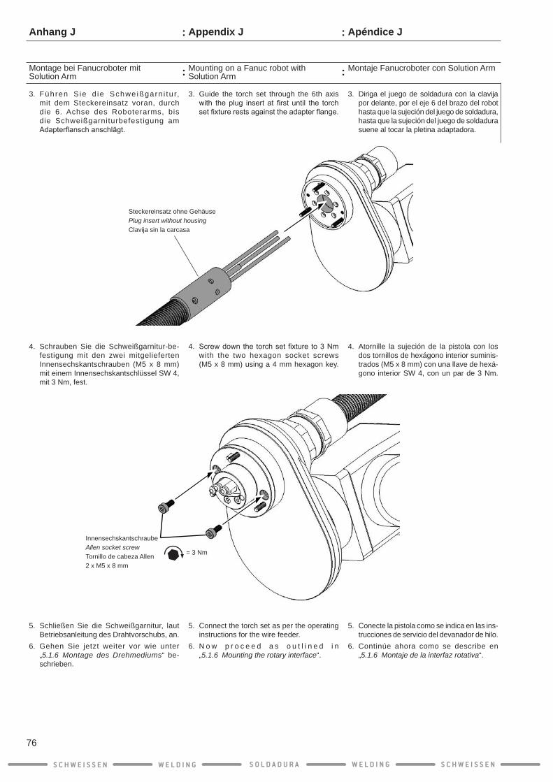
Montaje Fanucroboter con Solution Arm
3. Diriga el juego de soldadura con la clavija por delante, por el eje 6 del brazo del robot hasta que la sujeción del juego de soldadura, hasta que la sujeción del juego de soldadura suene al tocar la pletina adaptadora.
4. Atornille la sujeción de la pistola con los dos tornillos de hexágono interior suminis-trados (M5 x 8 mm) con una llave de hexá-gono interior SW 4, con un par de 3 Nm.
5. Conecte la pistola como se indica en las ins-trucciones de servicio del devanador de hilo.
6. Continúe ahora como se describe en „5.1.6 Montaje de la interfaz rotativa“.
Apéndice J
Mounting on a Fanuc robot with Solution Arm
3. Guide the torch set through the 6th axis with theplug insert at first until the torchsetfixturerestsagainsttheadapterflange.
4. Screwdownthetorchsetfixtureto3Nm with the two hexagon socket screws (M5 x 8 mm) using a 4 mm hexagon key.
5. Connect the torch set as per the operating instructions for the wire feeder.
6. N o w p r o c e e d a s o u t l i n e d i n „5.1.6 Mounting the rotary interface“.
Appendix J
Montage bei Fanucroboter mit Solution Arm
3. Führen S ie d ie Schwe ißgarn i tu r, mit dem Steckereinsatz voran, durch die 6. Achse des Roboterarms, bis die Schweißgarniturbefestigung am Adapterflanschanschlägt.
4. Schrauben Sie die Schweißgarnitur-be-festigung mit den zwei mitgelieferten Innensechskantschrauben (M5 x 8 mm) mit einem Innensechskantschlüssel SW 4, mit 3 Nm, fest.
5. Schließen Sie die Schweißgarnitur, laut Betriebsanleitung des Drahtvorschubs, an.
6. Gehen Sie jetzt weiter vor wie unter „5.1.6 Montage des Drehmediums“ be-schrieben.
Anhang J
S C H W E I S S E N W E L D I N G W E L D I N GS O L D A D U R A S C H W E I S S E N
76
Steckereinsatz ohne GehäusePlug insert without housingClavija sin la carcasa
: :
: :
= 3 Nm
InnensechskantschraubeAllen socket screwTornillo de cabeza Allen2 x M5 x 8 mm


![esp - · PDF fileesp pop edx Datum pop ecx ret add eax,[edx] push edi ret mov [edx], ecx ret pop edi ret ret pop edx ret Bachelorstudiengang Informatik/IT-Sicherheit](https://img.dokumen.tips/doc/110x75/5a9d34507f8b9a032a8c9609/esp-pop-edx-datum-pop-ecx-ret-add-eaxedx-push-edi-ret-mov-edx-ecx-ret-pop.jpg)


![STANDARDY WYMAGAŃ BĘDĄCE PODSTAWĄ …87 341 [01] Technik agrobiznesu 88 341 [02] Technik ekonomista 89 341 [03] Technik handlowiec 90 341 [04] Technik hotelarstwa 91 341 [05] Technik](https://img.dokumen.tips/doc/110x75/5f01b8527e708231d400b690/standardy-wymagaf-bdce-podstaw-87-341-01-technik-agrobiznesu-88-341-02.jpg)