Embed Size (px)
Citation preview

Dear Customer
Please find enclosed Amendment 16, effective 3 April 2018, to the Acceptable Solutions and Verification Methods for Clause B1 Structure of the New Zealand Building Code. The previous amendment to B1 was Amendment 15, 1 January 2017.
Section Old B1 B1 Amendment 16
Title pages Remove document history and status pages 1-4
Replace with new document history and status pages 1-4
Contents Remove page 9/10 Replace with new page 9/10
References Remove pages 11-14 Replace with new pages 11-14B
B1/VM1 Remove pages 17/18, 21–22F Replace with new pages 17/18, 21–22F
B1/VM4 Remove pages 57/58, 65/66 Replace with new pages 57/58, 65/66

Prepared by the Ministry of Business, Innovation and Employment
Acceptable Solutions and Verification Methods
For New Zealand Building Code Clause B1 Structure
B1

2
Status of Verification Methods and Acceptable Solutions
Verification Methods and Acceptable Solutions are prepared by the Ministry of Business, Innovation and Employment in accordance with section 22 of the Building Act 2004. Verification Methods and Acceptable Solutions are for use in establishing compliance with the New Zealand Building Code.
A person who complies with a Verification Method or Acceptable Solution will be treated as having complied with the provisions of the Building Code to which the Verification Method or Acceptable Solution relates. However, using a Verification Method or Acceptable Solution is only one method of complying with the Building Code. There may be alternative ways to comply.
Users should make themselves familiar with the preface to the New Zealand Building Code Handbook, which describes the status of Verification Methods and Acceptable Solutions and explains alternative methods of achieving compliance.
Defined words (italicised in the text) and classified uses are explained in Clauses A1 and A2 of the Building Code and in the Definitions at the start of this document.
Enquiries about the content of this document should be directed to:
Ministry of Business, Innovation and EmploymentPO Box 1473, Wellington 6140Telephone 0800 242 243Email: [email protected]
Verification Methods and Acceptable Solutions are available from www.building.govt.nz
© Ministry of Business, Innovation and Employment 2018
This document is protected by Crown copyright, unless indicated otherwise. The Ministry of Business, Innovation and Employment administers the copyright in this document. You may use and reproduce this document for your personal use or for the purposes of your business provided you reproduce the document accurately and not in an inappropriate or misleading context. You may not distribute this document to others or reproduce it for sale or profit.
The Ministry of Business, Innovation and Employment owns or has licences to use all images and trademarks in this document. You must not use or reproduce images and trademarks featured in this document for any purpose (except as part of an accurate reproduction of this document) unless you first obtain the written permission of the Ministry of Business, Innovation and Employment.

3
B1: Document History
Date Alterations
First published July 1992
Amendment 1 September 1993 p. ix–xii, References p. 1, 1.3, 1.4.1–1.4.3, 2.1, 2.2, 3.1–3.3, 4.1, 5.1 p. 2, 6.1, 6.2, 8.1, 9.1 p. 4, 11.1, 12.1 p. 5, 1.2, 2.1, 2.2, 3.1, 3.2,s 4.1, 4.2, 6.1, 6.2, 7.1
p. 9, 1.0.1, 1.0.5 b) c) p. 10, 2.3.5 p. 13, Figure 4 p. 14, 2.3.6 p. 16, 2.3.8, 2.3.9 p. 34, Table 1 p. 47, 1.0.1 pp. 49-54, Index
Amendment 2 19 August 1994 pp. i and ii, Document History pp. vii and viii, Contents pp. x and xi, References p. xiv, Definitions p. 1, 1.4.2, 5.1 p. 2, 6.1 p. 5, 1.3, 3.1, 4.1 p. 6, 7.1 p. 10, 2.3.5 p. 12, Figure 3 p. 13, Figure 4 p. 14, 2.3.6, 2.3.7
p. 15, Tables 4 and 5p.16, 2.4.1 p. 21, Figure 2 p. 22, Figure 3 p. 32, 2.2.4 p. 33, 1.0.2 p. 34, 3.2.1, Table 1 p. 35, 4.1, 4.1.2, 4.1.3, 4.2.1, 4.2.2, 4.3, 4.3.1, 5.0.1, Table 2 p. 36, 6.1.2, 7.1, 7.1.1 p. 37, 7.3.4pp. 49, 50, 51, 54, Index
ReprintedincorporatingAmendments 1 and 2
October 1994
Amendment 3 1 December 1995 p. ii, Document History p. ix, References p. 1, 3.1
p. 5, 6.2 p. 50, Index
Reprinted incorporating Amendments 1, 2 and 3
July 1996
Amendment 4 1 December 2000 p. ii, Document History pp. vii and viii, Contents pp. ix – xii, Revised References pp. xiii and xiv, Definitions
pp. 1–4A, Revised B1/VM1 pp. 5 and 6, Revised B1/AS1 pp. 33–63, Revised B1/VM4 p. 65, Revised B1/AS4 pp. 67–72, Revised Index
Erratum 9 February 2001 p. 46, 4.3.2 a) i)
Amendment 5 incorporating Erratum
1 July 2001 p. 2, Document Status p. 3, Document History p. 7, References
p. 41, 1.7.2 Comment p. 49, 2.2.4 p. 48, 1.9.1 b) i)
Amendment 6 1 March 2005 p. 11, References
Amendment 7 1 April 2007 pp. 11–12, 14, References pp. 15–16, Definitions
p. 18, 6.1
Document Status
The most recent version of this document (Amendment 16), as detailed in the Document History, is approved by the Chief Executive of the Ministry of Business, Innovation and Employment. It is effective from 3 April 2018 and supersedes all previous versions of this document.
The previous version of this document (Amendment 15) will cease to have effect on 30 June 2018.
People using this document should check for amendments on a regular basis. The Ministry of Business, Innovation and Employment may amend any part of any Verification Method or Acceptable Solution at any time. Up-to-date versions of Verification Methods and Acceptable Solutions are available from www.building.govt.nz

4
B1: Document History
Amendment 8 1 December 2008 p. 2, Document Status p. 3, Document History p. 9, Contentspp. 11–14, Referencespp. 15–16, Definitions
pp. 17–22B, B1/VM1p. 51, B1/VM4 1.0.5, 2.0.1p. 56, B1/VM4 Figure 2p. 70, B1/VM4 B1.0.2pp. 83–84, 86 Index
Amendment 9 30 September 2010 pp. 2–3, Document History, Status, pp. 11–14, Referencesp. 20, B1/VM1 2.2.13p. 21, B1/VM1 3.0, 5.1pp. 22–22B, B1/VM1 11.0pp. 23–24, B1/AS1 6.0, 6.1, 6.2, 6.3, 6.4, 7.1, 7.2, 7.3, 7.4
p. 27, B1/AS2 1.0.5p. 44, B1/AS3 1.7.9p. 47, B1/AS3 1.8.5, 1.8.6p. 49, B1/AS3 2.1.1, 2.2.4p. 63, B1/VM4 4.3.2p. 67, B1/VM4 5.3.1
Reprinted incorporatingAmendments 4–9
30 September 2010
Erratum 1 30 September 2010 p. 21, B1/VM1 3.1
Amendment 10 (Canterbury)
Effective from 19 May 2011 until 31 January 2012
p. 9, Contents p. 12–14, Referencesp. 15, Definitions p. 17, B1/VM1
p. 20, B1/VM1 2.2.14A to 2.2.14D
pp. 23–23C B1/AS1 1.4, 2.0, 3.0, 4.0p. 48, B1/AS3 1.9.3 p. 84, Index
Amendment 11 Effective from 1 August 2011 until 14 August 2014
p. 9, Contents p. 11–14, References p. 17–22B, B1/VM1 1.0, 2.0, 2.2.9, 2.2.14C, 5.2, 6.1, 7.1, 8.1, 12.1, 13.0
pp. 23–24, B1/AS1 1.2, 2.0, 3.0, 4.0, 7.0, 8.0, 9.0pp. 27–34, B1/AS2 pp. 83–87, Index
Amendment 12 Effective from 14 February 2014 until 31 May 2016
p. 9, Contents pp. 11–13, References pp. 15, 16, Definitions pp. 17, 18, 20, 22, 22A, 22B, B1/VM1 2.1, 2.2.6, 2.2.11, 5.2, 9.0, 12.1
pp. 23–23C, 24 B1/AS1 1.1, 1.2, 2.1.1–2.1.10, 3.1.9, 4.1.5, 8.0, 9.0 p. 79 , B1/VM4 C11.0
Amendment 13 Effective from 1 June 2016 until 30 May 2017
p. 13, References p. 24 , B1/AS1 7.3.3, 7.3.4
Amendment 14 Effective from 4 November 2016 until 30 May 2017
Effective from 1 January 2017 until 30 May 2017
p. 9 Contents p.p. 14 References p. 22 B1/VM1 3.1 d) p. 22C VM1 14.1.1
pp. 22C–22F B1/VM1 14.1, 14.1.2 - 14.1.22 pp. 23, 23B B1/AS1 2.1.3, 3.1.8 pp. 84, 87 Index
Amendment 15 Effective from 1 January 2017until 30 June 2018
p. 13 References p. 20 B1/VM1 2.2.14A, 2.2.14B p. 21 B1/VM1 3.1 p. 22B 13.1 p. 23A B1/AS1 3.1.2A, 3.1.2B, 3.1.2C
p. 24 B1/AS1 7.0 p. 37 B1/AS3 Scope p. 41 B1/AS3 1.7.2 p. 49 B1/AS3 2.2.4 p. 54 B1/VM4 3.3.2
Amendment 16 Effective 3 April 2018 p. 9 Contents pp. 11–14A References p. 18 B1/VM1 2.2.5
pp. 21-22 B1/VM1 3.1, 5.1 p. 57 B1/VM4 3.3.2 p. 65 B1/VM4 4.3.4
Page numbers relate to the document at the time of Amendment and may not match page numbers in current document.

Page
References 11
Definitions 15
Verification Method B1/VM1 17
General 17
1.0 General 17
2.0 Structural Design Actions 17 Standards
3.0 Concrete 21
3.1 NZS 3101: Part 1 21
4.0 Concrete Masonry 21
4.1 NZS 4230 21
5.0 Steel 21
5.1 NZS 3404: Part 1 21
5.2 AS/NZS 4600 22A
5.3 NASH Standard: Part 1 22A
6.0 Timber 22A
6.1 NZS 3603 22A
7.0 Aluminium 22A
7.1 AS/NZS 1664.1 22A
8.0 Earth Buildings 22B
8.1 NZS 4297 22B
9.0 Foundations 22B
10.0 Siteworks 22B
10.1 NZS 4431 22B
11.0 Drains 22B
11.1 NZS/AS 3725 22B
12.0 Windows 22C
12.1 NZS 4211 22C
13.0 Seismic Performance of 22C Engineering Systems in Buildings
13.1 NZS 4219 22C
14.0 Ductile Steel Mesh 22C
14.1 Grade 500E welded steel mesh 22C
Acceptable Solution B1/AS1 23
General 23
1.0 Explanatory Note 23
2.0 Masonry 23
Page
2.1 NZS 4229 23
3.0 Timber 23A
3.1 NZS 3604 23A
4.0 Earth Buildings 23C
4.1 NZS 4299 23C
5.0 Stucco 23C
5.1 NZS 4251 23C
6.0 Drains 23D
6.1 AS/NZS 2566.1 23D
6.2 AS/NZS 2566.2 23D
6.3 AS/NZS 2032 23D
6.4 AS/NZS 2033 23D
7.0 Glazing 24
7.1 NZS 4223 24
8.0 Small Chimneys 24
Verification Method B1/VM2 25 Timber Barriers
Acceptable Solution B1/AS2 27 Timber Barriers
Verification Method B1/VM3 35 Small Chimneys
Acceptable Solution B1/AS3 37 Small Chimneys
Contents
Amend 4 Dec 2000
Amend 11Aug 2011
9M I N I S T R Y O F B U S I N E S S , I N N O VAT I O N A N D E M P L O Y M E N T 3 A p r i l 2 0 1 8
Contents B1/VM1/VM2/VM3/VM4 & AS1/AS2/AS3/AS4
Amend 3 Dec 1995
Amend 8 and 16
Amend 10May 2011
Amend 10May 2011
Amend 10May 2011
Amend 4 Dec 2000
Amend 11Aug 2011
Amend 11Aug 2011
Amend 11Aug 2011
Amend 11Aug 2011
Amend 12Feb 2014
Amend 14Nov 2016
Amend 8Dec 2008

Scope 37
1.0 Chimney Construction 37
1.1 General 37
1.2 Chimney wall thickness 37
1.3 Foundations 37
1.4 Hearths 41
1.5 Chimney breasts 41
1.6 Reinforcing 41
1.7 Chimney restraint 41
1.8 Materials and construction 47
1.9 Systems to resist horizontal 47 earthquake loadings
2.0 Solid Fuel Burning Domestic 49 Appliances
2.1 Chimneys 49
2.2 Hearth slab 49
Verification Method B1/VM4 51 Foundations
1.0 Scope and limitations 51
2.0 General 51
3.0 Shallow Foundations 52
3.1 General provisions 52
3.2 Ultimate and design bearing 52 strength and design bearing pressure
3.3 Ultimate limit state bearing 52 strength for shallow foundations
3.4 Ultimate limit state sliding 58 resistance
3.5 Strength reduction factors 59
4.0 Pile Foundations 59
4.1 Ultimate vertical strength of 60 single piles
4.2 Column action 61
4.3 Ultimate lateral strength of 63 single piles
4.4 Pile groups 66
4.5 Downdrag 66
4.6 Ultimate lateral strength of 66 pile groups
4.7 Strength reduction factors 66
5.0 Pile Types 66
5.1 Concrete piles 66
5.2 Steel piles 67
5.3 Timber piles 67
Appendix A (Informative) 69
A1.0 Site Investigations 69
Appendix B (Informative) 70
B1.0 Serviceability Limit State 70 Deformations (Settlement)
Appendix C (Informative) 71
C1.0 Description of Wall, Limit States 71 and Soil Properties
C2.0 Earth Pressure Coefficients 72
C3.0 Load Factors and Strength 72 Reduction Factors
C4.0 Notation 72
C5.0 Loadings 73
C6.0 Surcharge Pressures at Toe 75
C7.0 First Ultimate Limit State (short 76 term static foundation bearing failure)
C8.0 Second Ultimate Limit State 77 (short term static foundation sliding failure)
C9.0 Third Ultimate Limit State 77 (short term foundation bearing failure under EQ)
C10.0 Fourth Ultimate Limit State 78 (short term foundation sliding failure under EQ)
C11.0 Fifth Ultimate Limit State 78 (long term foundation bearing failure)
C12.0 Sixth Ultimate Limit State 79 (long term foundation sliding failure)
C13.0 Comments 80
Acceptable Solution B1/AS4 81 Foundations (Revised by Amendment 4)
Index 83 (Revised by Amendment 4)
1 D e c e m b e r 2 0 0 8 D E PA R T M E N T O F B U I L D I N G A N D H O U S I N G10
Contents B1/VM1/VM2/VM3/VM4 & AS1/AS2/AS3/AS4
Amend 4 Dec 2000
Amend 4 Dec 2000
Amend 4 Dec 2000
Amend 4 Dec 2000
11
References B1/VM1/VM2/VM3/VM4 & AS1/AS2/AS3/AS4
References
M I N I S T R Y O F B U S I N E S S , I N N O VAT I O N A N D E M P L O Y M E N T 3 A p r i l 2 0 1 8
Amend 7 Apr 2007
Amend 8 Dec 2008
For the purposes of New Zealand Building Code compliance, the acceptable New Zealand and other Standards, and other documents referred to in these Verification Methods and Acceptable Solutions (primary reference documents) shall be the editions, along with their specific amendments, listed below. Where the primary reference documents refer to other Standards or other documents (secondary reference documents), which in turn may also refer to other Standards or other documents, and so on (lower order reference documents), then the applicable version of these secondary and lower order reference documents shall be the version in effect at the date these Verificaton Methods and Acceptable Solutions were published.
Where quoted Standards New Zealand
AS/NZS 1163: 2016 Cold-formed structural steel hollow sections VM1 5.1.1
AS/NZS 1170: Structural design actions – VM1 1.0, 2.1, 2.2, 5.2, 6.1, 7.1, 8.1 AS1 7.2, 7.3 Part 0: 2002 General principles VM4 2.0, B1.0 Amends: 1, 2, 3, 4, 5 Part 1: 2002 Permanent imposed and other actions Amends: 1, 2 Part 2: 2011 Wind actions Amends: 1, 2, 3 Part 3: 2003 Snow and ice actions Amend: 1
NZS 1170: Structural design actions – VM1 2.1, 2.2 Part 5: 2004 Earthquake actions – New Zealand
COMMENT
The above suite of Structural Design Action Standards, together with their amendments, are referred to collectively as “AS/NZS 1170”.
AS/NZS 1554: Structural steel welding Part 1: 2014 Welding of steel structures VM1 5.1.13 Amends: 1, 2
AS/NZS 1594: 2002 Hot-rolled steel flat products VM1 5.1.1
AS/NZS 1664: Aluminium structures – VM1 7.1 Part 1: 1997 Limit state design Amend: 1
AS/NZS 1748:- Timber – Stress graded for structural purposes VM1 6.1 Part 1: 2011 General requirements VM1 6.1 Amend: 1 Part 2: 2011 Qualification of grading method VM1 6.1 Amend: 1
AS/NZS 2032: 2006 Installation of PVC pipe systems AS1 6.3 Amend: 1
Amend 7 Apr 2007
Amends 8 and 9
Amend 9Sep 2010
Amends 10 and 11
Amend 11Aug 2011
Amend 11Aug 2011
Amend 11Aug 2011
Amend 12 Feb 2014
Amend 12 Feb 2014
Amend 12 Feb 2014
Amend 12 Feb 2014
Amend 12 Feb 2014
Amend 12 Feb 2014
Amend 16 Apr 2018
Amend 16 Apr 2018

AS/NZS 2033: 2008 Installation of polyethylene pipe systems AS1 6.4 Amends 1, 2
AS/NZS 2566: 2002 Buried Flexible pipelines. Part 1: 1998 Structural Design AS1 6.1 Part 2: 2002 Installation AS1 6.2
AS/NZS 2918: 2001 Domestic solid fuel heating appliances installation AS3 3.2.1, 2.2.4
NZS 3101:- Concrete structures standard Part 1: 2006 The design of concrete structures VM1 3.1, 3.1.2, 11.1 Amends: 1, 2, 3
NZS 3106: 2009 Design of concrete structures for the VM1 3.2 storage of liquids.
NZS 3109: 1997 Concrete construction AS3 1.8.2, 1.8.5 b), Amend: 1, 2 2.2.1 c), 2.2.3
NZS 3112:- Methods of test for concrete Part 2: 1986 Tests relating to the determination of strength of AS3 1.8.3 c) concrete Amend: 1, 2
NZS 3404:- Steel structures standard Part 1: 1997 Steel structures standard VM1 5.1 Amend: 1, 2
NZS 3603: 1993 Timber structures standard VM1 6.1, Amend: 1, 2 (Applies to building work consented VM4 5.3.1 prior to 1 April 2007) Amend: 1, 2, 4 (Applies to building work consented on or after 1 April 2007)
NZS 3604: 2011 Timber framed buildings AS1 1.4, 3.1, 4.1 AS3 1.1.1, 1.9.1 b), 1.9.2, 1.9.5, 2.2.1 b),
NZS 3605: 2001 Timber piles and poles for use in building VM4 5.3.1
NZS 3622: 2004 Verification of timber properties VM1 6.1 Amend: 1
123 A p r i l 2 0 1 8 M I N I S T R Y O F B U S I N E S S , I N N O VAT I O N A N D E M P L O Y M E N T
S T R U C T U R E References B1/VM1/VM2/VM3/VM4 & AS1/AS2/AS3/AS4
Amend 7 Apr 2007
Amend 11Aug 2011
Amend 7 Apr 2007
Amend 8 Dec 2008
Amend 6 Mar 2005
Amend 9Sep 2010
Where quotedAmend 9Sep 2010
Amend 9Sep 2010
Amend 9Sep 2010
Amend 11Aug 2011
Amend 9Sep 2010
Amend 10May 2011
Amend 7 Apr 2007
Amend 9Sep 2010
Amend 11Aug 2011
Amend 16 Apr 2018

NZS 3640: 2003 Chemical preservation of round and sawn timber VM4 5.3.1 Amends: 1, 2, 3, 4, 5
AS/NZS 3678: 2016 Structural steel – Hot-rolled plates, floorplates VM1 5.1.9 and slabs
AS/NZS 3679 Structural steel Part 1: 2016 Hot-rolled bars and sections VM1 5.1.9 Part 2: 2016 Welded l sections VM1 5.1.9
AS/NZS 3725: 2007 Design for installation of buried concrete pipes VM1 11.1
AS/NZS 3869: 1999 Domestic solid fuel burning appliances – AS3 2.1 Design and construction
AS/NZS 4058: 2007 Pre cast concrete pipes(pressure and non-pressure) VM1 11.1
NZS 4210: 2001 Code of practice for masonry construction: materials AS3 1.8.1, 1.8.3 (f and workmanship and g) Amend: 1
NZS 4211: 2008 Specification for performance of windows VM1 12.1
NZS 4219 : 2009 Seismic Performance of Engineering Systems VM1 1.3.1 in Buildings
NZS 4223:- Glazing in buildings Part 1: 2008 Glass selection and glazing AS1 7.1, 7.2.1, 7.3.7 Amend 1 Part 2: 2016 Insulating glass units AS1 7.2 Part 3: 2016 Human impact safety requirements AS1 7.3 Amend: 1 Part 4: 2008 Wind, dead, snow, and live actions AS1 7.4 Amend 1
NZS 4229: 2013 Concrete masonry buildings not requiring AS1 1.4, 2.1 specific engineering design AS3 1.1.1, 1.8.4, 1.9.2, 1.9.5, 2.2.1 b)
NZS 4230: 2004 Design of reinforced concrete masonry structures VM1 4.0 Amend: 1
NZS 4251:- Solid plastering AS1 5.1 Part 1: 2007 Cement plasters for walls, ceilings and soffits
NZS 4297: 1998 Engineering design of earth buildings VM1 8.1
13
References B1/VM1/VM2/VM3/VM4 & AS1/AS2/AS3/AS4
M I N I S T R Y O F B U S I N E S S , I N N O VAT I O N A N D E M P L O Y M E N T 3 A p r i l 2 0 1 8
S T R U C T U R E
Amend 8 Dec 2008
Amend 8 Dec 2008
Where quoted
Amend 8 Dec 2008
Amend 9Sep 2010
Amend 9Sep 2010
Amend 9Sep 2010
Amend 9Sep 2010
Amends 10 and 11
Amends 10 and 11
Amend 11Aug 2011
Amend 11Aug 2011
Amend 11Aug 2011
Amend 12 Feb 2014
Amends13 & 15
Amend 15Jan 2017
Amend 15Jan 2017
Amend 9Sep 2010
Amend 15Jan 2017
Amends 9 and 12
Amend 16 Apr 2018

NZS 4299: 1998 Earth buildings not requiring specific design AS1 1.4, 4.1 Amend: 1
NZS 4402:- Methods of testing soils for civil engineering VM1 11.1 purposes. Test 2.2: 1986 Soil classification tests – Determination of liquid limit Definitions Test 2.4: 1986 Soil classification tests – Determination of plasticity VM1 11.1 index Test 2.6: 1986 Soil classification tests – Determination of the linear shrinkage Definitions
Test 2.8.1: 1986 Soil classification tests – Standard method by wet VM1 11.1 sieving Test 2.8.2: 1986 Soil classification tests – Standard method by dry VM1 11.1 sieving Test 2.8.3: 1986 Soil classification tests – Standard method for fine VM1 11.1 soils (pipette method) Test 2.8.4: 1986 Soil classification tests – Subsidiary method for fine VM1 11.1 soils (hydrometer method) Test 4.1.1: 1986 Soil compaction tests – Determination of the dry VM1 11.1 density/water content relationship – New Zealand standard compaction test Test 4.2.1: 1988 Soil compaction tests – Determination of the VM1 11.1 minimum and maximum dry densities and relative density of a cohesionless soil – Minimum dry density
Test 4.2.2: 1988 Soil compaction tests – Determination of the VM1 11.1 minimum and maximum dry densities and relative density of a cohesionless soil – Maximum dry density Test 4.2.3: 1988 Soil compaction tests – Determination of the VM1 11.1, minimum and maximum dry densities and relative VM4 4.1.1 density of a cohesionless soil – Relative density
Test 5.1.1: 1986 Soil density tests – Determination of the density of VM1 11.1 soil – Sand replacement test for the determination of in situ density
NZS 4431: 1989 Code of practice for earth fill for residential VM1 10.1 development Amend: 1
AS/NZS 4600: 2005 Cold-formed steel structures VM1 5.2
AS/NZS 4671: 2001 Steel Reinforcing Materials AS1 2.1.5, 3.1.8 Amend: 1 AS3 1.8.5, VM1 14.0
AS/NZS 4680: 2006 Hot-Dip Galvanised (zinc) Coating AS3 1.8.6
AS/NZS 5131: 2016 Structural steelwork – Fabrication and erection VM1 5.1.3, 5.1.5-5.1.8, 5.1.10-5.1.12
143 A p r i l 2 0 1 8 M I N I S T R Y O F B U S I N E S S , I N N O VAT I O N A N D E M P L O Y M E N T
S T R U C T U R E References B1/VM1/VM2/VM3/VM4 & AS1/AS2/AS3/AS4
Where quoted
Amend 9Sep 2010
Amends 10 and 11
Amend 14 Nov 2016
Amends 10 and 11
Amend 16Apr 2018
Amend 16 Apr 2018

14AM I N I S T R Y O F B U S I N E S S , I N N O VAT I O N A N D E M P L O Y M E N T 3 A p r i l 2 0 1 8
Where quoted
SNZ HB 8630: 2004 Tracks and outdoor visitor structures VM1 2.2.9
The National Association of Steel Framed Housing Inc (NASH)
NASH Standard: Residential and Low Rise Steel Framing Part 1 2010 VM1 5.3 Design Criteria
British Standards Institution
BS 8004: 1986 Code of practice for foundations VM4 4.0.3
BS EN 14399 High-strength structural bolting assemblies for preloading Part 1: 2015 General requirements VM1 5.1.4 Part 2: 2015 Suitability for preloading VM1 5.1.4 Part 3: 2015 System HR. Hexagon bolt and nut assemblies VM1 5.1.2, 5.1.4 Part 5: 2015 Plain washers VM1 5.1.2, 5.1.4
Standards Australia
AS 1391: 2007 Metallic materials – Tensile testing at VM1 14.1.1 ambient temperature
AS 1397: 2001 Steel sheet and strip – Hot-dipped zinc-coated AS3 1.7.9 or aluminium/zinc-coated
AS 2159: 1995 Rules for the design and installation of piling VM4 4.0.3 (known as the SAA Piling Code) Amend: 1
American Society of Testing and Materials
ASTM D1143: 1981Test method for piles under static axial VM4 4.0.3 compressive load
New Zealand Geomechanics Society
Guidelines for the field descriptions of soils and rocks in engineering VM1 11.1 use. Nov 1988
New Zealand Legislation
Chartered Professional Engineers of New Zealand Act 2002 VM1 1.0
International Organization for Standardization
ISO 15630-2 2010: Steel for the reinforcement and and prestressing of VM1 14.1.1 concrete – Test Methods – Part 2 Welded Fabric
ISO 17025: 2005 General requirements for the competence of testing VM1 14.1.1 and calibration laboratories
Amend 8 Dec 2008
Amend 9Sep 2010
Amend 11Aug 2011
Amend 11Aug 2011
Amend 14 Nov 2016
Amend 14 Nov 2016
Amend 16 Apr 2018
Amend 8 Dec 2008

3 A p r i l 2 0 1 8 M I N I S T R Y O F B U S I N E S S , I N N O VAT I O N A N D E M P L O Y M E N T14B

17
S T R U C T U R E G E N E R A L
M I N I S T R Y O F B U S I N E S S , I N N O VAT I O N A N D E M P L O Y M E N T 1 4 F e b r u a r y 2 0 1 4
Verif ication Method B1/VM1
1.0 General
1.0.1 The Standards cited in this Verification Method provide a means for the design of structures to meet the performance requirements of New Zealand Building Code Clause B1 Structure. For any particular building or building design, the Verification Method shall consist of AS/NZS 1170 used in conjunction with the relevant cited material standards as modified by this Verification Method.
1.0.2 Modifications to the Standards, necessary for compliance with the New Zealand Building Code, are given against the relevant clause number of each Standard.
1.0.3 Citation of Standards in this Verification Method is subject to the following conditions.
a) The citation covers only the scope stated or implicit in each Standard. Aspects outside the scope, when applied to a particular building, are not part of the Verification Method.
b) Further limitations, modifications and/or constraints apply to each Standard as noted below.
c) Provisions in the cited Standards that are in non-specific or unquantified terms do not form part of the Verification Method. Non-specific or unquantified terms include, but are not limited to, special studies, manufacturer’s advice and references to methods that are appropriate, adequate, suitable, relevant, satisfactory, acceptable, applicable, or the like.
d) Where AS/NZS 1170 is used in combination with other Standards cited in this Verification Method and there are incompatibilities with these other Standards, then the underlying philosophy, general approach, currency of information and methods of AS/NZS 1170 are to take precedence.
e) An engineer with relevant experience and skills in structural engineering shall be responsible for interpretation of the requirements of the Standards cited when used for building structure design. A structural engineer who is chartered under the Chartered Professional Engineers of New Zealand Act 2002 would satisfy this requirement.
COMMENT
The Standards referenced in this Verification Method relating to building design require the application of specialist engineering knowledge, experience and judgement in their use.
2.0 Structural Design Actions Standards
2.1 The requirements of the AS/NZS 1170 suite of Standards are to be complied with. These comprise:
AS/NZS 1170.0: 2002 including Amendments 1, 2, 3, 4 and 5
AS/NZS 1170.1: 2002 including Amendments 1 and 2
AS/NZS 1170.2: 2011 including Amendments 1, 2 and 3
AS/NZS 1170.3: 2003 including Amendment 1,
and NZS 1170.5: 2004.
COMMENT
This suite of Standards, together with their amendments, are referred to collectively in this Verification Method as “AS/NZS 1170”.
2.2 The requirements of AS/NZS 1170 are subject to the following modifications.
2.2.1 Material Standards Where AS/NZS 1170 calls for the use of appropriate material Standards, only those material Standards referenced in this Verification Method B1/VM1 are included. Use of other Standards with AS/NZS 1170 must be treated as an alternative means of verification.
Verification Method B1/VM1 General
Amend 8 Dec 2008Amend 8
Dec 2008
Amend 10May 2011
Amend 11Aug 2011
Amend 11Aug 2011
Amend 11Aug 2011
Amend 11Aug 2011
Amend 11Aug 2011
Amend 11Aug 2011
Amend 12Feb 2014
2.2.2 Notes in AS/NZS 1170“Notes” that relate to clauses, tables or figures of AS/NZS 1170 are part of the Verification Method.
COMMENT
AS/NZS 1170 makes a general statement that notes are not an integral part of the Standard. However, in many cases the content of the notes makes them an integral part of the interpretation of the Standard. In these cases, the notes have been specifically cited as being part of this Verification Method.
2.2.3 AS/NZS 1170 Part 0, Clause 4.1 General Add the following to the end of the Clause:
“The combination factors for permanent actions (dead loads) are based on the assumption that they have a coefficient of variation of approximately 10%. Situations where this assumption is not valid are outside the scope of this Verification Method.”
2.2.4 AS/NZS 1170 Part 0, Clause 4.2.4 Replace the Clause with the following:
“The combination of actions for checking strength and stability for the ultimate limit state for fire shall be as follows:
(a) During the fire:
(i) [G, thermal actions arising from fire, ψ
l Q ]
together with:
(ii) a lateral force of 2.5% of (G + ψCQ)
applied as per Clause 6.2.2.
(b) After the fire until the building is either repaired or demolished:
(i) [G, thermal actions arising from fire, ψl Q ]
together with the more critical of either:
(ii) a lateral force of 2.5% of (G + ψCQ)
applied as per Clause 6.2.2.
or
(iii) a uniformly distributed horizontal face load of 0.5 kPa in any direction.
Account shall be taken of the effects of the fire on material properties and the geometry of the structure.”
2.2.6 AS/NZS 1170 Part 1, Table 3.2Replace the entry for “R2, Other roofs (i) Structural elements” with:
“R2 Other roofs (i) Structural elements 0.25 1.1”
Delete Note 2
Delete Note 3
2.2.7 AS/NZS 1170 Part 1, Clause 3.6 BarriersIn the first paragraph, second sentence, delete “… top edge or handrail…” and substitute “… top edge and rail…”
Delete the second paragraph and substitute:
“Apply as detailed below the uniformly distributed line loads (kN/m), uniformly distributed loads (kPa) and concentrated loads (kN) given in Table 3.3.
For the purposes of applying loads, a rail shall be any handrail or any top rail having a width in plan of greater than 30 mm.
The following are separate load cases, and one load at a time, either vertical or horizontal, is to be applied.
(a) Line loads (kN/m). Regardless of barrier height, line loads need not be applied more than 1200 mm above the floor (or stair pitch line):
(i) For domestic and residential activities, other residential (Row 2 of Table 3.3)
• For barriers with a rail or rails:
– apply the horizontal load to the top rail
3 A p r i l 2 0 1 8 M I N I S T R Y O F B U S I N E S S , I N N O VAT I O N A N D E M P L O Y M E N T18
S T R U C T U R E G E N E R A L Verif ication Method B1/VM1
Amend 8 Dec 2008
Amend 8 Dec 2008
Amend 11Aug 2011
Amend 12 Feb 2014
Amend 16 Apr 2018

2.2.15 NZS 1170 Part 5, Clause 4.2 Seismic weight and seismic mass After: “0.3 is the earthquake imposed action (live load) combination factor for all other applications” add the following:
“except roofs.
ψE = 0.0 is the earthquake imposed action
(live load) combination factor for roofs.”
2.2.16 NZS 1170 Part 5, Sections 5 and 6 Time history analysis Time history analysis is not part of this Verification Method.
COMMENT:
Time history analysis is a highly specialised method of assessing structural response to earthquakes. It requires many detailed and interdependent assumptions to be made in relation to the nature of earthquake shaking and its propagation from the source, the properties of the building site and the detailed characteristics of the building and its structural elements.
AS/NZS 1170 outlines the steps for time history analysis in some detail, but the applicability of each step needs to be evaluated on a building-by-building basis. More importantly, the output of the analysis needs to be examined carefully in each particular context.
Time history analysis can be an acceptable aid to verifying compliance with structural requirements provided that:
• It is carried out by specialists with in-depth experience in applying the technique.
• The output of the analysis and the viability of the resulting structural design are reviewed by an independent team experienced in both analysis and design.
2.2.17 NZS 1170 Part 5, Clause 5.2.2.3, equation 5.2(4) Delete equation 5.2(4) and replace with:
Cd(T) = C (T) Sp … 5.2(4) k
2.2.18 NZS 1170 Part 5, Clause 6.1.4.1 Requirement for modelling Delete the last sentence of the first paragraph and replace with:
“The model shall include representation of the diaphragm’s flexibility.”
Delete the third (last) paragraph.
3.0 Concrete
3.1 NZS 3101: Part 1 subject to the following modifications:
3.1.1 Clause 18.7.4.4 Detailing requirements for support of hollow core floors At the end of Clause 18.7.4.4 (b) add an
additional sentence:
“The details given by C18.6.7(e) may be applied to hollow-core units where the depth of the precast unit is equal to or less than 300 mm.”
3.1.2 Cast iron anchors and couplers may be used for designs that otherwise comply with NZS 3101 until 1 November 2018.
COMMENT:
The continued use of cast iron couplers and anchors until 1 November 2018 is subject to the anchor or coupler complying with relevant performance requirements set out in NZS 3101.
COMMENT:
Welded wire fabric that is used in designs to NZS 3101 is subject to the requirements of Paragraph 14.0 Ductile Steel Mesh of this Verification Method.
3.2 NZS 3106
4.0 Concrete Masonry
4.1 NZS 4230
5.0 Steel
5.1 NZS 3404: Part 1 subject to the following modifications:
5.1.1 Clause 2.2.1 Specification In Clause 2.2.1 a) replace:
“AS 1163 Structural steel hollow sections AS 1594 Hot-rolled steel flat products”,
with
“AS/NZS 1163 Cold-formed structural steel hollow sections
AS/NZS 1594 Hot-rolled steel flat products”
5.1.2 Clause 2.3.1 Steel bolts, nuts and washersIn Clause 2.3.1 add the following to the end of the Clause:
“BS EN 14399-3 High-strength structural bolting assemblies for preloading, System HR. Hexagon bolt and nut assemblies
21
S T R U C T U R E G E N E R A L
M I N I S T R Y O F B U S I N E S S , I N N O VAT I O N A N D E M P L O Y M E N T 3 A p r i l 2 0 1 8
Verif ication Method B1/VM1
Amend 8Dec 2008
Amend 16 Apr 2018
Amends 8 and 9
Amend 8 Dec 2008
Amends 9, 14, 15, 16, Err 1
Amend 9 Sep 2010
Amend 9Sep 2010
Amend 16 Apr 2018

BS EN 14399-5: High-strength structural bolting assemblies for preloading, Plain washers”
5.1.3 new Clause 3.10 Documentation Insert the following after clause 3.9:
“Clause 3.10 Documentation
The requirements in AS/NZS 5131 Section 4.1.1 General shall be applied.”
5.1.4 Clause 9.3.1 Bolts and bolting categoryIn Clause 9.3.1.2 replace:
“and AS 1559”
with
“, AS 1559, BS EN 14399.1, BS EN 14399.2, BS EN 14399.3 and BS EN 14399.5”.
5.1.5 Section 14 Fabrication Replace Section 14 Fabrication with the following:
“14 Fabrication
The fabrication of steel structures shall be in accordance with AS/NZS 5131.
Construction categories for the purposes of this Standard shall be determined in accordance with Appendix C of AS/NZS 5131.”
5.1.6 Section 15 Erection Replace Section 15 Erection with the following:
“15 Erection
The erection of steel structures shall be in accordance with AS/NZS 5131.
Construction categories for the purposes of this standard shall be determined in accordance with Appendix C of AS/NZS 5131.”
5.1.7 Section 16 Modification of Existing Structures Replace Section 16 Modification of existing structures with the following:
“16 Site modifications during erection and modification and repair of existing structures
Site modifications during erection and modification and repair of existing structures shall be in accordance with AS/NZS 5131 Section 14 Site modifications during erection and modification and repair of existing structures.”
5.1.8 new Section 18 Architecturally Exposed Structural Steelwork
Insert the following after Section 17:
“18 Architecturally exposed structural steelwork
The requirements in AS/NZS 5131 Section 10 Architecturally exposed structural steelwork shall be applied.”
5.1.9 Appendix AReplace references to AS/NZS 3678, AS/NZS 3769.1 and AS/NZS 3679.2 in NZS 3404 with the 2016 versions that are referenced in this Verification Method
5.1.10 Appendix D Replace Appendix D Inspection of Welding to AS/NZS 1554.1 with the following:
“Appendix D Inspection of Welding
The recommendations in AS/NZS 5131 Appendix I Inspection of Welding and Bolting. (Informative) should be used.”
5.1.11 Appendix K Replace Appendix K Standard test for evaluation of slip factor (normative) with the following:
“Appendix K Standard test for evaluation of slip factor (normative)
The requirements in AS/NZS 5131 Appendix G Standard test for evaluation of slip factor shall be used.”
5.1.12 Appendix L Replace Appendix L Inspection of bolt tension using a torque wrench (informative) with the following"
“Appendix L Inspection of bolt tension using a torque wrench (informative)
The recommendations in AS/NZS 5131 Appendix H Inspection of bolt tension using a torque wrench should be used.”
5.1.13 new Appendix R Insert the following after Appendix Q:
“Appendix R Selection of materials for the avoidance of lamellar tearing (informative)
The guidance in AS/NZS 1554.1 Appendix H Selection of materials for the avoidance of lamellar tearing should be used.”
3 A p r i l 2 0 1 8 M I N I S T R Y O F B U S I N E S S , I N N O VAT I O N A N D E M P L O Y M E N T22
S T R U C T U R E G E N E R A L Verif ication Method B1/VM1
Amend 16 Apr 2018
Amend 16 Apr 2018

22AM I N I S T R Y O F B U S I N E S S , I N N O VAT I O N A N D E M P L O Y M E N T 1 4 F e b r u a r y 2 0 1 4
5.2 AS/NZS 4600 subject to the following modifications:
a) Actions must be determined in accordance with AS/NZS 1170. All references to NZS 4203 are replaced by equivalent references to AS/NZS 1170.
b) The term “normative” identifies a mandatory requirement for compliance with this Standard.
c) The term “informative” identifies information provided for guidance or background which may be of interest to the Standard’s users. Informative provisions do not form part of the mandatory requirements of the Standard.
d) Where this Standard has provisions that are in non-specific or unquantified terms then these do not form part of the Verification Method and the proposed details must be submitted to the territorial authority for approval as part of the building consent application. This includes, but is not limited to, special studies and manufacturer’s advice.
e) All stages of construction of a structure or part of a structure to which this Standard is applied shall be adequately reviewed by a person who, on the basis of experience or qualifications, is competent to undertake the review.
f) The extent of the review to be undertaken shall be nominated by the design ngineer, taking into account those materials and work- manship factors which are likely to influence the ability of the finished construction to perform in the predicted manner.
g) At the end of the first paragraph of Appendix A add the words “Unless noted otherwise a document referred to below shall be the version of that document current at the date of issue of this Standard or if amendments are cited to this Standard in the “References” pages of this document at the latest date of those amendments.”
h) Appendix B shall be read as normative with “shoulds” changed to “shalls”.
5.3 NASH Standard – Residential and Low- rise Steel Framing Part 1: Design Criteria.
6.0 Timber
6.1 NZS 3603 subject to the following modifications:
a) Actions must be determined in accordance with AS/NZS 1170. All references to NZS 4203 are replaced by equivalent references to AS/NZS 1170.
b) Delete Clause 2.2.1.2 and replace with:
“Machine stress-grading shall be in accordance with AS/NZS 1748 as modified by NZS 3622. Machine stress-graded timber shall have its properties verified, and be identified, in accordance with the requirements of NZS 3622.”
7.0 Aluminium
7.1 AS/NZS 1664.1 subject to the following modifications:
a) Actions must be determined in accordance with AS/NZS 1170. All references to NZS 4203 are replaced by equivalent references to AS/NZS 1170.
b) The terms “capacity factor” and “strength limit state” are to be read as “strength reduction factor” and “ultimate limit state” respectively.
c) Where this Standard has provisions that are in non-specific or unquantified terms then these do not form part of the Verification Method and the proposed details must be submitted to the territorial authority for approval as part of the building consent application. This includes, but is not limited to, special studies and manufacturer’s advice.
d) All stages of construction of a structure or part of a structure to which this Standard is applied shall be adequately reviewed by a person who, on the basis of experience or qualifications, is competent to undertake the review.
e) The extent of the review to be undertaken shall be nominated by the design engineer, taking into account those materials and workmanship factors which are likely to influence the ability of the finished construction to perform in the predicted manner.
Amend 12 Feb 2014
Amend 11 Aug 2011
S T R U C T U R E G E N E R A LVerif ication Method B1/VM1
Amend 8 Dec 2008
Amend 8 Dec 2008
Amend 8 Dec 2008
Amend 11 Aug 2011
Amend 8 Dec 2008
Amend 7 Apr 2007
Amend 11Aug 2011
Amend 11Aug 2011
Amends 8 and 11

1 4 F e b r u a r y 2 0 1 4 M I N I S T R Y O F B U S I N E S S , I N N O VAT I O N A N D E M P L O Y M E N T22B
f) Clause 1.2 to read “MATERIALS This Standard applies to aluminium alloys listed in Table 3.3(A) that comply with AS 1734, AS 1865, AS 1866, AS 1867 and AS 2748.1.”
g) At the end of the first paragraph of Clause 1.4 add the words “Unless noted otherwise a document referred to below shall be the version of that document current at the date of issue of this Standard or if amendments are cited to this Standard in the “References” pages of the Acceptable Solutions and Verification Methods at the latest date of those amendments.”
8.0 Earth Buildings
8.1 NZS 4297 subject to the following modifications:
Actions must be determined in accordance with AS/NZS 1170. All references to NZS 4203 are replaced by equivalent references to AS/NZS 1170.
9.0 Foundations
See B1/VM4.
10.0 Siteworks
10.1 NZS 4431
11.0 Drains
11.1 AS/NZS 3725 subject to the following modifications:
Clause 3 Add to the list of reference documents:
“NZS 3101 The design of concrete structures.
NZS 4402 Methods of testing soils for civil engineering purposes: Tests 2.4, 2.8, 4.1.1, 4.2.1, 4.2.2, 4.2.3 and 5.1.1.
New Zealand Geomechanics Society, Guidelines for the field description of soils and rocks in engineering use.”
Clause 4 In the paragraph headed “(c) Select fill”, after the words “given in Table 1” add “or the New Zealand Geomechanics Society Guidelines”.
Clause 5 In definition of Pt, replace “AS 4058” with “AS/NZS 4058”
Clause 6.4 Replace the word “may” with “shall”. Delete the words “Superimposed concentrated dead loads should be avoided.”
Clause 6.5.3.1 Delete the words “The appropriate road vehicle loading shall be specified by the relevant highway authority or owner”.
Clause 6.5.3.2.2.2 Replace the word “may” with “shall”.
Clause 6.5.4.3 Delete the words “unless otherwise specified by the Relevant Authority”.
Clause 6.5.5 Delete the first words “For” and after the words “for aircraft types” add the words “is outside the scope of this Standard but...”
Clause 7 Replace the word “should” with “shall”.
Clause 10.3 After the words “the test load” add “or proof load”.
Appendix A Delete “Normative” and replace with “Informative”
Appendix B Delete “Normative” and replace with “Informative”
Amend 9 Sep 2010
Amend 9Sep 2010
S T R U C T U R E G E N E R A L Verif ication Method B1/VM1
Amend 12Feb 2014
Amend 11Aug 2011
Amend 12Feb 2014
Amend 8Dec 2008

22CM I N I S T R Y O F B U S I N E S S , I N N O VAT I O N A N D E M P L O Y M E N T 4 N o v e m b e r 2 0 1 6
12.0 Windows
12.1 NZS 4211 subject to the following modification:
References to air leakage, water leakage and operational effectiveness of opening sashes in NZS 4211, are non-structural considerations and do not apply to this document.
13.0 Seismic Performance of Engineering Systems in Buildings
13.1 NZS 4219 subject to the following modifications in the Canterbury earthquake region:
The zone factor Z shall be determined from the Standard but shall not be less than 0.3.
14.0 Ductile Steel Mesh
14.1 Grade 500E welded steel mesh
Where Grade 500E welded steel mesh is specified, it shall meet the requirements of AS/NZS 4671 subject to the following modifications.
14.1.1 Laboratory accreditation
COMMENT:
Amendment 14 to Verification Method B1/VM1 is effective from 4 November 2016, except for this Paragraph 14.1.1 which is effective from 1 January 2017.
Laboratories that provide testing and certification of Grade 500E welded steel mesh for use in New Zealand must be accredited for testing to ISO 17025: General requirements for the competence of testing and calibration laboratories, with a scope of accreditation that includes:
• ISO 15630-2: 2010 Steel for the reinforcement and prestressing of concrete – Test methods – Part 2 Welded fabric.
• AS 1391: 2007: Metallic materials – Tensile testing at ambient temperature
• AS/NZS 4671: 2001 Steel Reinforcing Materials as modified by this Verification Method.
Accreditation must be by a signatory to the International Laboratory Accreditation Cooperation (ILAC) Mutual Recognition Arrangement (MRA).
COMMENT:
International Accreditation New Zealand (IANZ) in NZ and the National Association of Testing Authorities (NATA) in Australia are signatories to the ILAC MRA. Details of signatory accreditation bodies in other economies are available on request from IANZ or directly from the ILAC website at http://ilac.org/signatory-search/?q=all
Test certificates must be endorsed i.e. must carry the symbol of their accreditation body and/or a statement that they are accredited, by a named accreditation body, for the reported tests.
14.1.2 Interpretation and Clarification of AS/NZS 4671
Where conflicting or contradictory information is found between AS/NZS 4671:2001 and Standards it references, AS/NZS 4671:2001 takes precedence.
14.1.3 AS/NZS 4671 Clause 3.1 Ageing
Delete Clause 3.1 and replace with:
“The test samples must be brought up to a surface temperature of 100±10°C (i.e. the surface of the steel is recorded at 100 ± 10°C) then held at 100±10°C for 60 minutes (+15, -0 minutes). The method used to generate the temperature increase can be a suitable calibrated oven (calibrated for both temperature and temperature spatial distribution) or boiling water.
”Once heating is completed as detailed above, the samples are to be cooled in still air to ambient room temperature.“
Amend 14Nov 2016
Amend 14 Nov 2016
Amend 14Jan 2017
Amend 8Jun 2008
S T R U C T U R E G E N E R A LVerif ication Method B1/VM1
Amend 14 Nov 2016
Amend 11Aug 2011
Amend 15Jan 2017
Amend 12Feb 2014
Amend 11Aug 2011

4 N o v e m b e r 2 0 1 6 M I N I S T R Y O F B U S I N E S S , I N N O VAT I O N A N D E M P L O Y M E N T22D
14.1.4 AS/NZS 4671 Clause 9.3 Labelling of reinforcing steel
Add a line:
“9.3 (a)(vii) that Grade 500E steel mesh complies with Paragraph 14 of B1/VM1.”
Add a line:
”9.3 (b)(vi) that Grade 500E steel mesh complies with Paragraph 14 of B1/VM1.“
14.1.5 AS/NZS 4671 Appendix A
Delete Appendix A.
14.1.6 AS/NZS 4671 Clause B1.1
Insert ”through steel processing“ after ”steel melting“.
14.1.7 AS/NZS 4671 Clause B1.3.1
Delete paragraph (b) and replace with:
”Unless specified differently in Clauses other than Clause B1.3.1 in AS/NZS 4671, a batch shall be:
For mesh products:
(i) A quantity of mesh not exceeding 1000 sheets produced from steel of the same surface geometry and nominal diameter, of the same nominal strength grade and of the same ductility class and the mesh is manufactured in the same run under the same conditions using the same equipment; or
(ii) Where sheets of mesh have steel wires that differ in any of surface geometry, diameter, nominal strength grade, or ductility class, a quantity of mesh not exceeding 1000 sheets considering each type of steel separately (e.g. if different types of steel wires are used in each direction then the wires in each direction will be considered a separate batch).“
COMMENT:
In (i) above, the term ‘same run’ allows for breaks in production (e.g. overnight or weekends etc. provided the other criteria remain constant).
14.1.8 AS/NZS 4671 Clause B1.3.5
Delete and replace with:
”The minimum length of specimen test piece will be determined by the requirement to obtain a test piece including at least one welded
intersection and a gauge length for the measurement of elongation remote at least 20 mm from the welded intersections. Furthermore, additional length of the test piece will be required to keep both the welded intersection and gauge length of the elongation measurement remote at least 20 mm from the jaws of the testing machine.
”There is no maximum limitation imposed on the length of the test piece. The test piece must not be subject to any post-production treatment that will unduly affect the test result.“
14.1.9 AS/NZS 4671 Clause B1 Scope and general
Add a Clause:
”B1.4 For grade 500E steel mesh, all test certificates produced in compliance with AS/NZS 4671 shall note that they are compliant with B1/VM1 Paragraph 14.“
14.1.10 AS/NZS 4671 Clause B3 (c)
Delete Amendment No 1 June 2003 to Clause B3 (c)(i).
Delete Clause B3 (c) i and ii and replace with:
”(i) Mechanical properties, one test per batch on each of three separate longitudinal bars and three separate transverse bars (i.e. 6 tensile tests). If different grade ductility class, surface geometry or nominal diameter edge bars are used on the mesh, one extra tensile test per batch is required on the differing edge bars per sheet.
(ii) Weld-shear tests, one test per batch on each of three separate intersections from different wires. If different grade ductility class, surface geometry or nominal diameter edge bars are used on the mesh, one extra shear test per batch is required on the differing edge bars per sheet.“
Add after (v):
”(vi) Where a manufacturer can demonstrate long-term quality compliance for mesh with respect to Re, Agt and Rm/Re in accordance with Clause B6, the testing frequencies required in Clause B3 (c)(i) may be reduced to one test on each of two separate longitudinal and two transverse
Amend 14Nov 2016
Amend 14 Nov 2016
S T R U C T U R E G E N E R A L Verif ication Method B1/VM1

22EM I N I S T R Y O F B U S I N E S S , I N N O VAT I O N A N D E M P L O Y M E N T 4 N o v e m b e r 2 0 1 6
bars (i.e. 4 tensile tests). However, the testing requirement on edge wires will remain unchanged from Clause B3 (c)(i).“
14.1.11 AS/NZS 4671 Clause B4.1.1 Batch parameters
Add a Clause:
”The individual results for Agt shall be rounded to 0.1% and for Rm/Re to 0.01 and the average of these results shall be then rounded.“
14.1.12 AS/NZS 4671 Clause B4.1.2
Delete the first sentence and replace with:
”A batch analysis shall be undertaken at the completion of all batch testing undertaken in accordance with Clause B3. The batch shall be deemed to conform with the tensile parameters specified in Table 2 if the following criteria are satisfied:“
Add a second line to Clause B4.1.2(b)
”For mesh manufactured from Grade 500E, all individual test sample results of Agt must be a minimum of 6%.“
14.1.13 AS/NZS 4671 Clause B5
Add to the last sentence of paragraph 2:
”along with the original test results.“
14.1.14 AS/NZS 4671 Clause B6
Add a comment:
”COMMENT:
Long-term conformance is shown by completing a statistical analysis in accordance with clause B6 on the collected batch results. Clause B6.3 requires all production and processing to be subject to continual control in accordance with Clause 8 and Clause B6. Clause B6.3 makes it mandatory to undertake batch testing.“
14.1.15 AS/NZS 4671 Clause B6.1
Add the following to the end of the last sentence of paragraph 2:
”and including a minimum of four separate batches.“
Add the following sentence:
”If different grade ductility class, surface geometry or nominal diameter edge bars are used on the mesh, then a separate analysis for long-term quality level shall be carried out on these bars.“
Delete the Note to Clause B6.1 in Amendment No 1: June 2003.
Add the following paragraph:
”For New Zealand, the application of long-term quality compliance for mesh with respect to Agt and Rm/Re may be waived, at the choice of the manufacturer. However, all batch test results in the long-term compliance review must meet the requirements defined in Clause B4.“
14.1.16 AS/NZS 4671 Clause B6.2.1
Add a comment:
”COMMENT:
The mean and standard deviation are to be calculated from the individual test values for each test sample from each batch as defined in Section B2.“
14.1.17 AS/NZS 4671 Clause B6.3
Add a comment:
”COMMENT:
Clause 6.3 requires all production and processing to be subject to continued control in accordance with Clause 8 and Appendix B. Appendix B provides two pathways to compliance: using long-term conformance; and not using long-term conformance.
”When using long-term conformance:
• Individual batches (defined in B1.3.1) are subjected to testing in accordance with Clause B3 and evaluated to the requirement of Clause B4.
• A batch will fail the initial testing if it does not comply with all requirements of Clause B4.1.2 or Clause B4.2.
• If the additional testing on twice as many test samples (i.e. 12 tensile pieces or six weld shear pieces) for the specific parameter investigated, do not meet the requirements of Clause B4.1.2 or Clause B4.2, then the batch will have failed to comply with the Standard and needs to be downgraded and removed from the data for long-term quality analysis.“
Add a sentence after the existing sentence as follows:
”Where the sample size of a batch falls between sample sizes given in Table B1, the value of the multiplier ‘K’ may be interpolated linearly between the next lowest and next highest number of samples given in Table B1 Statistical Multiplier ‘K’.“
Amend 14Nov 2016
Amend 14 Nov 2016
S T R U C T U R E G E N E R A LVerif ication Method B1/VM1
4 N o v e m b e r 2 0 1 6 M I N I S T R Y O F B U S I N E S S , I N N O VAT I O N A N D E M P L O Y M E N T22F
Add a comment:
”COMMENT:
Clause B6.3 details the conformance criteria and makes reference to CvL (the lower characteristic value of a variable parameter) and CvU (the upper characteristic value of a variable parameter). For Re, these are detailed in Table 2 of the Standard as 500 MPa and 600 MPa respectively. One interpretation is that the 95% and 105% allowances can be applied to these having relied on the CvL: p=0.95, and CvU: p=0.05 figures in Table 2 to make this allowance. This is incorrect.
”The p-values are provided to indicate that this is a 90% confidence level and are used to determine the correct ‘K’ statistical multiplier from Table B1 that should be applied to the sample test results dataset, and to calculate the required confidence interval. These p-values are not to be used to expand the lower and upper limits of 500 MPa and 600 MPa within which the confidence interval is required to fall. The same issue exists for Agt and Rm/Re unless the manufacturer has waived the Long-term quality level (LTQL) for these parameters.“
14.1.18 AS/NZS 4671 B6.4
Add a Clause after B6.3:
“B6.4 Non-conformance to long-term quality levels
Where steel of welded mesh is sourced on the spot market from random different suppliers, then Clause B6 cannot be used and Clause B7 must be used to show conformance.
14.1.19 AS/NZS 4671 Clause B7.2
Add the following before the first paragraph:
”Individual batches must be subjected to testing in accordance with Clause B7.2 and Clause B7.3.
”The results shall be evaluated against the requirements of Clause B7.4.1 (a) and Clause B7.4.2.
”If the steel does not comply with the requirements of Clause B7.4.1 (a) then it shall be subjected to additional testing in accordance with Clause B7.4.1 (b).
”If the additional results fail to meet the specified values, the batches are deemed to be non-conforming and the manufacturer/supplier must demonstrate ongoing compliance through B7 until a new LTQL can be established in accordance with B6.1 (for example 200 test results).“
Add a comment:
”COMMENT:
Test piece and specimen have the same meaning.“
14.1.20 AS/NZS 4671 Clause B7.3
Add a line in Clause B7.3(a) after (iv):
”(v) Shear strength of joints in mesh“
14.1.21 AS/NZS 4671 Clause B7.4.1(a)(iii)
Delete the two equations and replace them with:
COMMENT:
The error in these equations only appears to affect downloaded copies of AS/NZS 4671.
14.1.22 AS/NZS 4671 Clause C2.2.2
Delete all but the last sentence and replace with:
”The uniform elongation Agt shall be determined in accordance with ISO 15630-2 with the following permitted amendments:
(a) a minimum extensometer gauge length of 50 mm may be used
(b) for measurements taken after failure gauge marks of up to 25 mm may be used.“
Amend the last sentence by deleting ”unless otherwise agreed between the parties concerned.“
Add a sentence after the last sentence:
”Where possible when testing for Agt, the gauge length for the measurement of elongation shall exclude the welded intersection.“
152.33s15 Rek.L; and
152.33s15 Rek.U;
Amend 14Nov 2016
Amend 14 Nov 2016
S T R U C T U R E G E N E R A L Verif ication Method B1/VM1
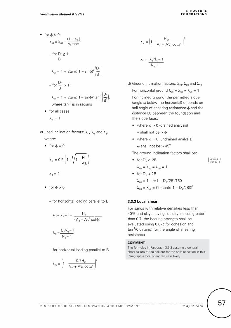
• for f > 0:
lcd = lqd – (1 – lqd)
Nq tanf
– for Df <_ 1:
Bl
lqd = 1 + 2tanf(1 – sinf)2( Df___B
l ) – for
Df___B
l > 1:
lqd = 1 + 2tanf(1 – sinf)2tan-1( Df___B
l ), where tan-1 is in radians
• for all cases
lgd = 1
c) Load inclination factors: lci, lqi and lgi
where:
• for f = 0
lci = 0.5 ( 1 +l 1 – ___H ) lqi = 1
• for f > 0
– for horizontal loading parallel to LI
lqi = lgi = 1– ______Huf______ ____ (Vuf + AIcI cotfI)
lci = lqiNq – 1
_______ Nq – 1
– for horizontal loading parallel to BI
lqi = (1 0.7Huf
_ ______________)3
Vuf + AIcI cotfI
lgi = (1
Huf
_ ______________)3
Vuf + AIcI cotfI
lci = lqiNq – 1
________
Nq – 1
d) Ground inclination factors: lcg, lqg and lgg
For horizontal ground lcg = lqg = lgg = 1
For inclined ground, the permitted slope (angle v below the horizontal) depends on soil angle of shearing resistance f and the distance De between the foundation and the slope face:,
• where f >_ 0 (drained analysis)
v shall not be > f
• where f = 0 (undrained analysis)
v shall not be > 45° The ground inclination factors shall be:
• for De ≥ 2B
lcg = lqg = lgg = 1
• for De < 2B
lcg = 1 – v(1 – De /2B)/150
lqg = lgg = (1 – tan(v(1 – De/2B)))2
3.3.3 Local shear
For sands with relative densities less than 40% and clays having liquidity indices greater than 0.7, the bearing strength shall be evaluated using 0.67c for cohesion and tan-1(0.67tanf) for the angle of shearing resistance.
COMMENT:
The formulae in Paragraph 3.3.2 assume a general shear failure of the soil but for the soils specified in this Paragraph a local shear failure is likely.
57
S T R U C T U R EF O U N D AT I O N S
M I N I S T R Y O F B U S I N E S S , I N N O VAT I O N A N D E M P L O Y M E N T 3 A p r i l 2 0 1 8
Verif ication Method B1/VM4
AIsu
Amend 16 Apr 2018

3.4 Ultimate limit state sliding resistance
3.4.1 When the loading is not normal to the foundation base, foundations shall be checked for failure by sliding.
3.4.2 The ultimate sliding resistance shall comprise the sum of the ultimate sliding strength between the base of the foundation and the ground, and any available passive earth pressure in the direction of sliding at the side of the foundation.
3.4.3 Passive earth pressure shall not be considered if:
a) For foundations in clay soils, it is possible that the clay could shrink away from the vertical faces of the foundation, or
b) The possibility exists that the soil in front of the foundation may be removed by erosion or by building or landscaping work in the future.
3.4.4 For drained conditions, the ultimate sliding strength shall be:
S = cIAI + VI tandI
The value of dI shall be taken as the angle of shearing resistance (fI) of the foundation soil for cast-in-situ concrete foundations and 0.67fI for smooth precast foundations.
3.4.5 For undrained conditions, the ultimate sliding strength shall be:
S = AIsu
1 D e c e m b e r 2 0 0 0 D E PA R T M E N T O F B U I L D I N G A N D H O U S I N G58
S T R U C T U R EF O U N D AT I O N S Verif ication Method B1/VM4
Figure 3:
Bearing Strength Factors Paragraphs 3.3.2 and 4.1.3

Hu
2 2Hu
+ f – 2Mult = 0
__ ______ 3 9D s
The location of the maximum pile shaft moment is obtained from the same equation as for the long free head pile.
4.3.4 Drained lateral strength of piles in cohesionless soil
a) Free head piles
i) short free head piles
The ultimate lateral strength of a short free head pile is:
Hu =
KpDsL3g
________
2(f + L)
The location, measured from the ground surface, of the maximum pile shaft moment is:
gs =
2Hu
______
3KpgDs
The maximum pile shaft moment is:
Mmax = Hu 2 2Hu
_ _______ + f
3 3KpDsg
ii) long free head piles
The ultimate lateral strength of a long free head pile is obtained by solving the following equation:
Hu 2 2Hu + f – Mult = 0
_ _______
3 3KpDsg
The location of the maximum pile shaft moment (Mult) is obtained from the same equation as for the short pile.
b) Restrained head piles
i) short restrained head piles
The ultimate lateral strength of a short restrained head pile is:
Hu = 1.5KpDsL2g
The magnitude of the maximum pile head moment is:
Mmax = Hu( 2L + f)
_
3
If Mmax is greater than Mult then the intermediate length case, ii) below, is appropriate.
ii) intermediate restrained head piles
The ultimate lateral strength of an intermediate length restrained head pile is:
Hu =
KpDsL3g Mult
________ + _____
2(f + L)
f + L
The location, measured from the ground surface, of the maximum pile shaft moment is:
gs =
2Hu ______
3KpDsg
The pile shaft moment at this depth is:
Mmax = Hu 2 2Hu
_ _______ + f – Mult
3 3KpDsg
If Mmax calculated from this equation is greater than Mult then the long case, iii) below, is appropriate.
65
S T R U C T U R EF O U N D AT I O N S
M I N I S T R Y O F B U S I N E S S , I N N O VAT I O N A N D E M P L O Y M E N T 3 A p r i l 2 0 1 8
Verif ication Method B1/VM4
Amend 16 Apr 2018
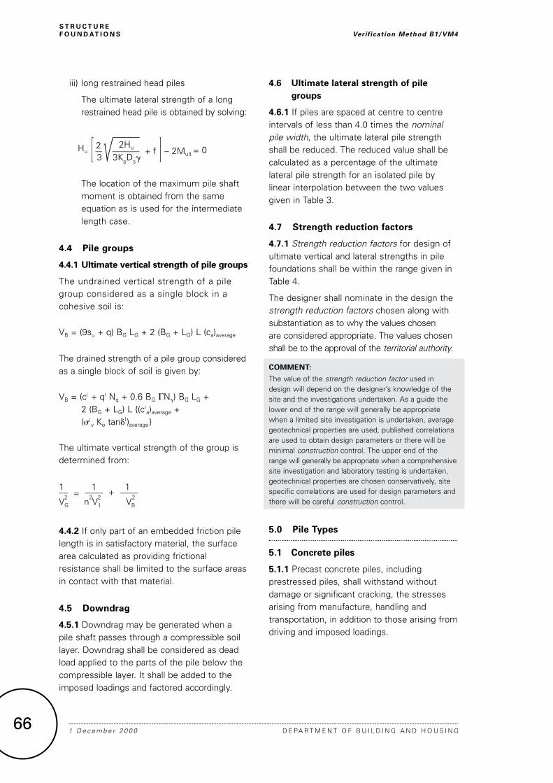
iii) long restrained head piles
The ultimate lateral strength of a long restrained head pile is obtained by solving:
Hu 2 2Hu
+ f – 2Mult = 0
__ ______ 3
3KpDsg
The location of the maximum pile shaft moment is obtained from the same equation as is used for the intermediate length case.
4.4 Pile groups
4.4.1 Ultimate vertical strength of pile groups
The undrained vertical strength of a pile group considered as a single block in a cohesive soil is:
VB = (9su + q) BG LG + 2 (BG + LG) L (ca)average
The drained strength of a pile group considered as a single block of soil is given by:
VB = (cI + qI Nq + 0.6 BG GNg) BG LG + 2 (BG + LG) L {(cI
a)average + (sI
v Ko tandI)average }
The ultimate vertical strength of the group is determined from:
1 1 1
__ = ____ + ____ V
2 n
2V
2 V
2
G 1 B
4.4.2 If only part of an embedded friction pile length is in satisfactory material, the surface area calculated as providing frictional resistance shall be limited to the surface areas in contact with that material.
4.5 Downdrag
4.5.1 Downdrag may be generated when a pile shaft passes through a compressible soil layer. Downdrag shall be considered as dead load applied to the parts of the pile below the compressible layer. It shall be added to the imposed loadings and factored accordingly.
4.6 Ultimate lateral strength of pile groups
4.6.1 If piles are spaced at centre to centre intervals of less than 4.0 times the nominal pile width, the ultimate lateral pile strength shall be reduced. The reduced value shall be calculated as a percentage of the ultimate lateral pile strength for an isolated pile by linear interpolation between the two values given in Table 3.
4.7 Strength reduction factors
4.7.1 Strength reduction factors for design of ultimate vertical and lateral strengths in pile foundations shall be within the range given in Table 4.
The designer shall nominate in the design the strength reduction factors chosen along with substantiation as to why the values chosen are considered appropriate. The values chosen shall be to the approval of the territorial authority.
COMMENT:
The value of the strength reduction factor used in design will depend on the designer’s knowledge of the site and the investigations undertaken. As a guide the lower end of the range will generally be appropriate when a limited site investigation is undertaken, average geotechnical properties are used, published correlations are used to obtain design parameters or there will be minimal construction control. The upper end of the range will generally be appropriate when a comprehensive site investigation and laboratory testing is undertaken, geotechnical properties are chosen conservatively, site specific correlations are used for design parameters and there will be careful construction control.
5.0 Pile Types
5.1 Concrete piles
5.1.1 Precast concrete piles, including prestressed piles, shall withstand without damage or significant cracking, the stresses arising from manufacture, handling and transportation, in addition to those arising from driving and imposed loadings.
1 D e c e m b e r 2 0 0 0 D E PA R T M E N T O F B U I L D I N G A N D H O U S I N G66
S T R U C T U R EF O U N D AT I O N S Verif ication Method B1/VM4


![HPRP Plan Amendment FINAL Revised 9-16-09[1]](https://img.dokumen.tips/doc/110x75/577d2f8d1a28ab4e1eb20936/hprp-plan-amendment-final-revised-9-16-091.jpg)
