Embed Size (px)
Citation preview
Office of Naval Research
Department of the Navy
Contract N00014-67-0094-0009
B. ~fJi { COPY f 1 ~ c
HY. ROOV£' A~ t ·~s LABORATORY CALIFOR.·!IJ.i IN.::·: !fUTE OF TEChNOLOGY
PASJ\DENA 4. CALIFORNIA
SOME HYDRODYNAMIC ASPECTS
OF SUPERFLUID HELIUM
by
Din-Yu Hsieh
Division of Engineering and Applied Science
CALIFORNIA INSTITUTE OF TECHNOLOGY
Pasadena, California
Report No. 85-36 December 1966
Office of Naval Research Department of the Navy
Contract N00014 -67-0094-0009
SOME HYDRODYNAMIC ASPECTS OF SUPERFLUID HELIUM
by
Din-Yu Hsieh
Reproduction in whole or in part is permitted for any purpose of the United States Government
Distribution of this Document is Unlimited
Division of Engineering and Applied Science California Institute of Technology
Pasadena, California
Report No. 85-36 December 1966

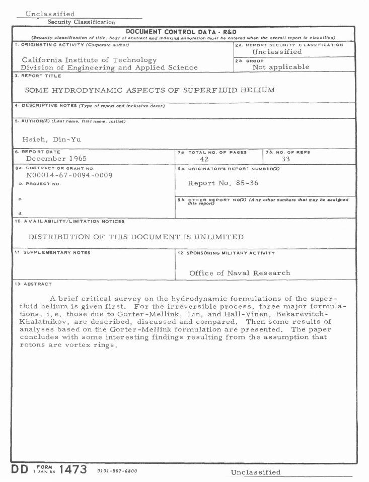
Abstract
A brief critical survey on the hydrodynamic formulations of the
superfluid helium is given first. For the irreversible process, three
major formulations, i.e. those due to Gorter -Mellink, Lin, and Hall
Vinen, Bekarevitch-Khalatnikov, are described, discussed and compared.
Then some results of analyses based on the Gorter -Mellink formulation
are presented. The paper concludes with some interesting findings
resulting from the assumption that rotons are vortex rings .

Some Hydrodynamic Aspects of Superfluid Helium
I. Introduction.
The substance He4 was first liquefied in 1908( 1 ). Its boiling
point is 4. 21 "K., and it has a critical point with temperature 5. 21<. and
pressure 2. 26 atm. Shortly after the liquefication of helium, it was
found(2
) that the liquid helium will undergo a phase transition at 2.18 "K.
This transition divides the liquid helium into two phases; the higher
temperature phase is customarily called He I, while the lower tempera-
ture phase, He II. For the equilibrium property of the liquid, the phase
transition is marked by, among others, a sharp maximum and a dis
continuity of the slope in the density curve(3
), and a logarithmic singular
ity in the specific heat curve(4
), ( 5 ). The shape of the specific curve
leads to the terms "\.-transition" and "\.-point1'.
When the liquid is in motion, He I behaves like what one would
expect any ordinary liquid at such low temperature. On the other hand,
He II exhibits some very strange or "super" properties. We may mention:
(i) The ability to flow through extremely narrow channels ( 6 ) (super-
fluidity).
(ii) The normal damping of oscillations of immersed bodies(?).
(iii) The appearance of a fountain from a capillary when its other end is
stuffed with powder and heated by radiation (8
) (fountain effect).
(iv) The rise of temperature after the outflow through powder-plugged
orifice (9)' (1 O) (mechano -caloric effect).
() T . f (11), (12),(13) ( d d) v he propagation o temperature waves secon soun .
(vi) The apparent loss of the super properties when the speed of liquid
2.
exceeds certain critical value(l 4 ), (lS).
The peculiar properties of the superfluid helium are largely
accountable on the basis of the phenomenological two-fluid theory( 11 )' (l2}.
According to this theory, the liquid is considered to be a kind of mixture
of two components, a normal component and a superfluid component.
The density of the fluid p, can thus be separated into a normal density
pn and a superfluid density p s
(1)
In the same manner, the fluid motion, characterized by its local velocity,
~· may also be considered to be due to the concerted motions of the
fluid components, so that
p~ = p v + p v n-n s-s ( 2)
where v and v are velocities of normal and superfluid components -n -s
respectively. The normal component behaves just like any normal fluid,
while the superfluid component is frictionless and carries no entropy.
The microscopic basis of the two-fluid theory of the liquid helium
is somewhat different from the two-fluid theories of ordinary mixtures.
Take an ordinary mixture, say, ionized gases; its components, say
electrons and ionized atoms, are well defined physical particles whose
detailed motion one can mentally or even actually follow. The components
of He II, on the other hand, reveal themselves only collectively as a
bulk fluid element. That we can not isolate in the classical sense the
particles of normal and superfluid components is mainly due to the fact
that He II is a fluid for which the quantum effects is important even in
3
the macroscopic scale.
A d . h '1' h . 1 h (l 2) th 1 ccor 1ng to t e preva1 1ng p ys1ca t eory , e norma
component motion is a revelation of excitations in the superfluid "back-
ground". The superfluid background is the ground state liquid helium,
hence is at zero temperature. They are not necessarily stationary in
the macros co pic sense, for whether the bulk fluid is in motion or not is
a relative matter. The motion of those macroscopic elements of "back-
ground" is revealed through ::[ s. The excitations in liquid helium is very
much like the excitations in solids. In fact, here we also have phonons.
In addition to phonons, we have "rotons" and other types of excitations.
Based on this physical theory, we can obtain the macroscopic momenta
and energy by the appropriate summation of the microscopic momenta and
energies. However, the normal and superfluid densities are not basic,
but derived quantities. Complete consistency is still lacking between the
microscopic physical theory and the macroscopic hydrodynamic theory.
In establishing the hydrodynamic theory of the liquid helium we still rely
mainly on the arguments of continuum mechanics while incorporating it
with the qualitative essentials of the microscopic theory.
II. Reversible Hydrodynamic Equations.
Based on the two-fluid theory, the following set of hydrodynamic
equations may be derived(lZ), (16), (l?).
~tp + "V • [ E pv + (1- E) pv ] = 0 ( 3) u -n -s
4
ov -n 1 1-E -at + < v • \7) v = - - \7 P - ---n -n p E
( 5)
ov -s ~ + (v • 'V)v o1: -s ,...s = - ..!._ 'Vp + s'VT - \7 n + .!,.. 'V(v -v ) 2
p ,:. -n -s ( 6)
where p is the pressure; T, the temperature; s, the entropy per unit
mass carried by the fluid; n, the potential of the external force field;
pn ; and E =
p ap
r= <;;v.n +Y'·(p v )= u~ n~n
ap -[-s + V'·( p v )] 8t s-s
the source density of the normal fluid.
We need only to remark that besides the ideas of the two-fluid
theory, the approaches and arguments used in establishing the previous
equation are those usually employed in ordinary mechanics of continuum;
and as in elsewhere, the ultimate justification is the agreement with the
physical reality. In that respect, the theory is quite successful. The
phenomena {i), {iii), (iv} and (v} are satisfactorily explainable by the
linearized version of the above set of equations, mainly due to the pres-
senceofthethermal-mechanical terms s\i'T in Eqs. (5} and (6). In
equations (5) and (6 ), the term, r
-(v -v ) -, may be interpreted as -n -s E p
the average increment of v in unit time due to the interactions between -n
normal and superfluid "particles", while 21
{v -v )2 is (aau) , U{p, s,e) -n -s E
{17) p,s being the internal energy density of the fluid .
Multiply (5} by p , (6) by p and then add, we obtain: n s
Dy_l Dt
+ - \7. [p v v + p v v -p vv] = p n-n-n s-s-s --
1 - \i'p - \i'~L p
(7)

D where Dt
a = at + (~ · \l) is the particle derivative with respect to time.
Multiply (5) bY Pn'.:n• (6) p s~s, and then add, we obtain
[
Ev' D n ( 1 -E) 2 Dt -2- + -2- vs + u] = - l
v 2 v 2 1 Pnn Pss - 'V· -- (v -v) + --p 2 -n ~ 2
(v -v)+pv -s ,.., -
( 8)
where the pressure and temperature are related to U by
2 (au) p=p a p S, E
and T =(~~) p,E
We may note that the divergence term in the left-hand side of (7) is the
apparent stress due to diffusive transfer of momentum, which appears
in every mixture. The divergence term in the right-hand side of (8),
5
arises from the energy flux and the physical meanings of various terms
are quite clear.
Equations (7) and (8) represents the principles of conservation
of momentum and energy, and are obtainable independent of the mech-
anism of interaction between normal and superfluid "particles" . On the
other hand, the terms with r and V (v -v )2 in Eqs. (5) and (6) arises ,...n -s
because of the assumption of a particular kind of interaction, i. e. , the
superfluid velocity v is not a thermal average, thus all superfluid ~s
"particles 11 should have the same velocity v and any change of v due -s ~s
to interactions would be a change for all "particles". The validity of
this assumption has not been explicitly verified experimentally. The
experimental study of second sound, being of small amplitude, serves
only to establish the terms s'VT in Eqs. (5) and (6 ). Here we suggest
6
possible ways to test its validity, i.e. the study of propagation of finite
amplitude waves.
For simplicity, let us make the approximations
p = p(P ) T = T(s)
and limit the considerations in such temperature range that it is approxi-·
• E • mately true - 1s a constant. Then we can show that the characteristic
s
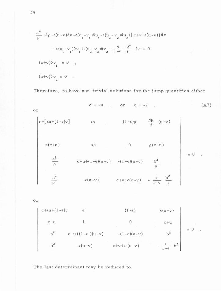
speeds c satisfy the following equation: (Appendix A)
c4 +c3 [2(u+v)}t-c2 [u2 +v2 +4uv-a2 -b2] +c{2uv(u+v)-2[(1-e)u+ev]a2
-2 [ e u+ ( 1 -e}v] b 2 }
+ {u2 v 2 -[ (1-e )U:2 +ev2
] a 2- [ eu2 +(l-e)v2
] b 2 +a2 b 2 }
+(u-v){c3 +c2 [(l+e)u+(2 -e)v] +c[ eu2 +(l-e)v2 +2uv-a2] +[ eu2 v+(l-e)uv2
-a2 (u-eu+ev)] } = 0 (9)
where a and b are the speeds of first and second sound respectively,
and u and v are the components of velocities of normal and super
fluids in the direction normal to the characteristic surface. The last
term with the factor (u-v) would be missing if terms with Y' (v -v )2
"'!1 ..... s
are missing in Eqs. (5) and (6 ). Thus the determination of the charac-
teristic speeds can tell whether these terms are there.
We note that if u and v are small in comparison with both a
and b , (9) will reduce to
leading to the acoustic limit, independent of the presence of the term
with factor (u-v) in Eq. (9). That is why we need the study of finite
amplitude waves to decide the is sue.
7
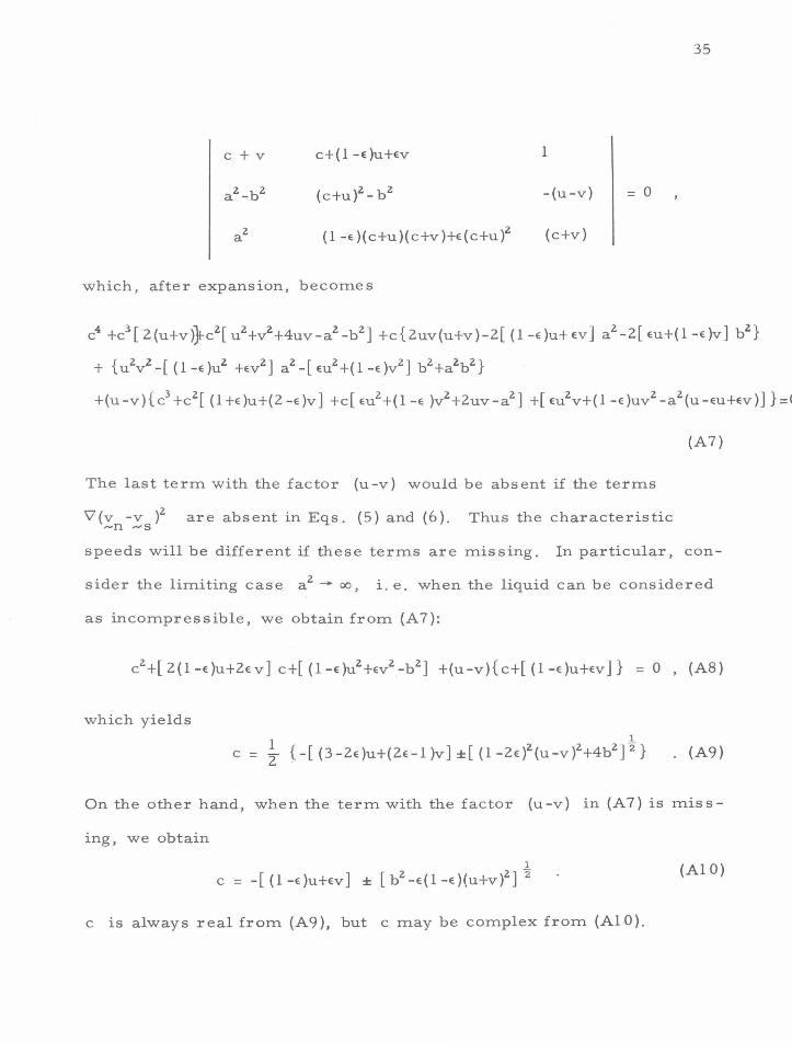
When u and v are small in comparison with a, but not
necessarily b, i.e . . when the fluid may be considered as incompres-
sible, it may be obtained from (9) that
1
c = ~ {-[(3-2e)u+(2e-1)v] ± [(l-2e)2 (u-v)2 +4b2]"
2} ( l 0)
On the other hand, if the last term with factor (u-v) in (9) is missing,
we obtain 1
c = [ (1-e)u + ev) ± [b2 -e(l-e )(u+v)2 J 2 ( 11 )
Equation (1 0) implies that c will always be real, while Eq. (11) may
permit complex values of c. As the complex value of c implies the
instability of the system, just like the case of ordinary barotropic
fluid if it should turn out that ~~ < 0. Therefore it is more likely that
the terms Y(v -v )2 should be present in Eqs. (5) and (6), even from "'n "'S
a continuum mechanics point of view.
In addition to Eqs. (3) - (6 ), a further condition of local irrota-
tionality is usually imposed on the superfluid component:
"VXv =0 ,...,s
This condition like Eqs. (5) and (6) can also be established from two
( 12)
approaches: One from the variational principle of a macroscopic
fluid(l 6 ),(l?). The other based on the microscopic argument that since
He4 are Bose particles, therefore there are only very few excitations
at low energy to keep the meaningful existence of the superfluid com-
ponent. The "superfluid" component, being a giant quantum system with
d . . b . 1' . . t' 1( 18 ) concerte mohon, lS y 1mp 1cat1on 1rrota 1ona .
Lin(l 9 ) criticized both approaches. In particular, he pointed out
8
that in the variational approach, an additional condition to insure the
definite identification of . the fluid particles should be imposed. Then no
restriction on the irrotationality of superfluid component would follow.
Though it is a well thought point, and gives correct formulation for
ordinary compressible fluids, here it may also be argued that we should
not apply this extra condition because He4 are Bose particles. Again,
we may need experiments ·for the final clarification on this issue.
III. Irreversible Hydrodynamic Equations.
The fundamental Eqs. (3) - (6) will be modified in order to
account for the irreversible process. Equation (4) should be changed
to
o(ps) + 'V·(psv + q) = Q ot -n -
( 13)
where .S. represents the non-convective heat flux, and Q the entropy
production due to ordinary thermal conduction and frictional dis sipa-
tions. To the right hand side of (5) and (6), we should add
1 - [ -F + F ] p ~n - sn
n
1 and - [ -F - F ] ,
p - s ~ sn s
respectively, where F is the ~n
frictional force term for t he normal component, F, ~s
the frictional
force term for the superfluid component, and F is the mutual friction .-sn
term. The nature of these newly introduced terms is still largely an un-
settled question.
The necessity to introduce these additional terms is again dicta-
ted by the experimental observations. The implication in the two fluid
theory that normal component is normal leads to the term F . And F , ,.....,n ,....,n
without evidence to the contrary, is naturally assumed to arise from
9
the ordinary viscous stresses. Similarly, we have the ordinary thermal
conduction term in ,1·
It seems also natural to assume that F = 0 on account of the ,..,s
phenomenon of superfluidity. But, as pointed out by London(l?) and
Lin ( 11
), the absence of F may result from the irrotationality of the ,..,s
superfluid component rather than the absence of the viscosity. In this
sense, shear strains in the superfluid component could still exist and
momentum may be transmitted without causing dissipation. An experi
ment to settle this point has been suggested by London ( 17
), and as yet
has not been performed. The phenomenon of superfluidity may even
be due to the inefficiency of interaction between the superfluid compon-
ent and the wall of confinements, even though the superfluid component
is neither inviscid nor intrinsically irrotational, as suggested by Lin ( 19 ).
The apparent loss of superfluidity when the flow speed of He II
exceeds certain critical values leads to the introduction of mutual
friction. Microscopically, the existence of critical velocities implies
that there should be other types of low energy excitation besides phonons
and rotons. This led to the development of the concept of quantized
vortex lines(lB), whose basic features have now been supported by
experimental observations(ZO), (Zl )_ Except where there are only a
few vortex lines or rings, the idea of quantized vortex lines is not too
helpful from macroscopic point of view. All it says is that when the
flow is supercritical, the superfluid component is practically rotational
and frictional. It does serve the basis of a kinetic model to derive the
macroscopic mutual friction. However, when many such vortex lines
are present, it is indeed very difficult to calculate the interaction out
10
of their entanglements. Thus other forms of mutual friction have also
been suggested directly from a semi-empirical basis.
In the following we shall describe and discuss three different
formulation:
(i) The Gorter -Mellink formulatioJ22
). For this formulation,
we take F = 0 ~. s
( 14)
K VT q = T ( 15)
(-F n\ =ax: {~(a~~~ + a~~ -} oik a;~ ) +C oik a~~} . i, k =I. 2, 3
( 1 6)
F = ap(1-e )e J v -v j 2 (v -v ) ~ sn -s -n -s ~n
( 1 7)
and 2
Q = q~ (liT)' +(.(ll·o:n)' + 11 nl + (
ov . ov nk
2 ~ oxi - - 6
2 ov nJ. ) 3 ik ax:;-
+ apE (1 -E )(v -v )4
} -s ..... n ( 18)
where 11 and s are coefficients of shear and bulk viscosity respectively,
and a is the coefficient of mutual friction.
The boundary conditions art:> such that relative to the boundary
surface, the perpendicular component of the total mass flux be zero, the
perpendicular component of the heat flux be continuous, and the tangential
component of normal fluid velocity be zero.
We may remark that for problems involving bulk fluid flows, q
and Q can usually be neglected because of the extreme efficiency of
heat transfer by the internal convection.
11
(ii) The formulation by Lin(l 9 ). For the case of incompressible
fluids, we have in this formulation:
-F ,_n (nn)("'72. = 11 v v ,....n ( 1 9)
(20)
and
F .....-sn + pE( 1 -E) (V' X v ) X (v -v )
"'s ~n ..-s (21 )
This formulation recognizes neither irrotationality nor inviscid-
ness in the superfluid component. The second term in (21) is, strictly
speaking, not a mutual friction term, since it does not conbribute to
dissipation. It is absent when the flow is irrotational. We put it here
for the convenience of comparison. Disregard this term for the moment,
we see J·ust like -F + F = .,.., (nn)'lz v + .,.., (ns )92. v we also have ~n "'sn 'I -n 'I ~s'
-F -F =11(sn)V'zv +11(ss)'lzv, exceptanassumption 11(ss)+11(ns)=O ~s ,..,sn ,..,n ----s
is made to have only the viscous effect of the normal component present
in the equation governing the total fluid. Because of (21), we need ad-
ditional boundary condition to govern the velocity of the superfluid com-
ponent. Instead of the non-slip condition which governs the normal com-
ponent, it is suggested that the tangential component of the shear stress
vector will be directly related to the slip velocity:
(22)
where 1 is the stress vector at the boundary, with unit normal .!::• i.e.
T ~s) = n. [11 (sn)( 8vni + 8vnj)- 11 (ns)( 8v si + ();sj )] ' 1 J B"x." B"x." ~ X.
J 1 J 1
(s) w is the velocity
of the superfluid component relative to the boundary, and the subscript
12.
a signifies the tangential direction. Superfluidity at low speeds of He II
suggests that F(s) will vanish with w(s), thus as an approximation we
could put
(iii) The formulati on due to Hall and Vinen (2. 3 ), and Bekarevich
and Khalatnikov(24
). For this formulation, we have
~ = ~ Y'T (24)
( -F ) = n. 1
n1 + a { (
av . 8xk ll ~
- F = -w X ( \7 X }... v] -s ~ ~
F = - [ p Y'{ s Y'·p (v -v )+s \7. v } ] ~ sn s 3 s -s -n 1 -n
+[B wX s+B v X (w X s)- B v(w·s)] 1- - 2 ~ - - 3- - r'
Q = - K -- + .:.!. ~ + -n- - - 6 . + S (\7. v )2 l { (Y' T )2 ., ( ov ni ov nk 2 ov nJ. ) z T T 2 a~ oxi 3 1k ax; 2 -n
+ s ['l·p (v -v )] 2 +21; (Y'·v )[Y'·p (v -v )] 3 s -s -n 1 -n s -s -n
+ B
z
w
(25)
(26)
(27)
(28)
1 where w = V X v , S = v -v -
- -s - -n -s ps \l X }...v, v =--=--, K,Y],S ,!; ,S, ,
- - Jwl z 1 3
B , B , B and }... are coefficients responsible for thermal conduction, 1 2 3
viscosities and mutual frictions . For boundary condition, let N be the
13
unit normal vector at the surface of the boundary, and u the velocity
of the boundary, we then have
--s ,.., { v - u +
(29)
in addition to the non-slip condition for v , the vanishing and continuity -n
of the perpendicular components of the total mass and heat fluxes.
Equation (29) is derived from the consideration of the dissipation at the
surface due to vortex slippage, and t;b and t;b are the boundary dissipa
tion coefficients.
This last formulation is certainly the most complete among the
three, and it is also appealing, since essentially the same equations can
be derived from either a continuum approach or a microscopic physical
model. But it is also a set of very complex equations highly non-linear,
and involving many undetermined physical coefficients, thus it is difficult
to compare with specific results. In (27), the terms in the second bracket
is present only when w = 0, this is the outcome of the rotation of the
superfluid component or the quantized vortex lines. In the microscopic
physical model, the force is transmitted from the normal component to
the vortex lines through the collisions between rotons and the vortex
lines, and then treating the vortex lines as some foreign filament with
circulation, the force is transmitted to the superfluid component through
the Magnus effect. The term associated with B 3
is longitudinal, i. e . ,
the force is in the direction of vorticity, while the terms associated
with B and B are transverse. Also the term associated with B 1 z 1
does not contribute to the dissipation.
The mutual firction of Gorter -Mellink could be easily incorporated

14
in the formulation HVBK, from a continuum point of view. But as they
now stand, there is a fundamental difference. In the formulation HVBK,
though it may not be possible to establish a theorem on the permanence
of vorticity for the superfluid component, it is readily seen that irrota-
tional flow is a permissible state of motion, while in the Gorter-Mellink
formulation, the superfluid component cannot be rotation free because
of the mutual friction.
Lin's formulation is quite different from the other two formula-
tions, but from a continuum point of view, it has as legitimate a
theoretical basis as the other two. This only shows how primitive is
our knowledge about the hydrodynamics of He II. The nonlinear and
irreversible aspects of the flow of He II are still very much unexplored.
A simple problem that may serve to show the different conclusions
drawn frorn Lhese three formulations is the steady parallel flow of He II
through a circular pipe. (Appendix B).
For this problem, we assume that the fluids are incompressible,
all the physical coefficients constant, and we look for flows such that in
cylindrical coordinates (r' e' z)' we have
v = (O,O,u(r)) .... n
and v = ( 0, 0, v ( r) ) -s
Then it is found that for all three formulations,
which is a constant, and
ap 1fZ = -A
(3 0)
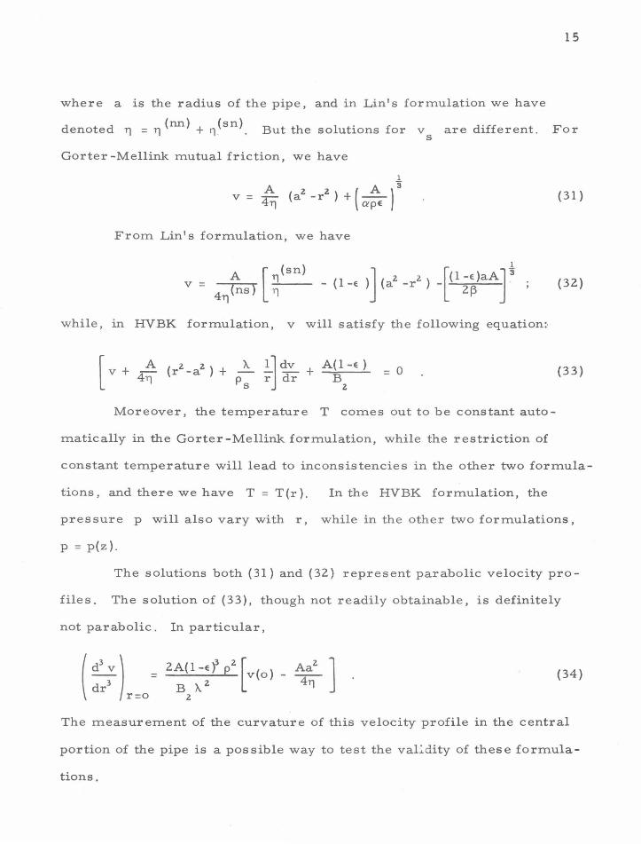
15
where a is the radius of the pipe, and in Lin's formulation we have
denoted 11 = 11 (nn) + 11 (sn) . But the solutions for v are different . For s
Gorter -Mellink mutual friction, we have
1
A z z ( A )3
v = -::r- (a -r ) + --<±TJ apE
(31)
From Lin's formulation, we have
v - ~,., ____ _ A [ (sn)
- 4TJ(ns) ll (32)
while, in HVBK formulation, v will satisfy the following equation:·
(33)
Moreover, the temperature T comes out to be constant auto-
matically in the Gorter -Mellink formulation, while the restriction of
constant temperature will lead to inconsistencies in the other two formula-
tions, and there we have T = T(r ). In the HVBK formulation, the
pressure p will also vary with r , while in the other two formulations,
p = p(z) .
The solutions both (31) and (32) represent parabolic velocity pro-
files. The solution of (33), though not readily obtainable, is definitely
not parabolic. In particular,
( d
3 v) = 2A(l-Ef p
2 [v(o) _ Aa
2 ]
d 3 B X. z 4TJ r r=o z
(34)
The measurement of the curvature of this velocity profile in the central
portion of the pipe is a possible way to test the vai::.dity of these formula-
tions.
16
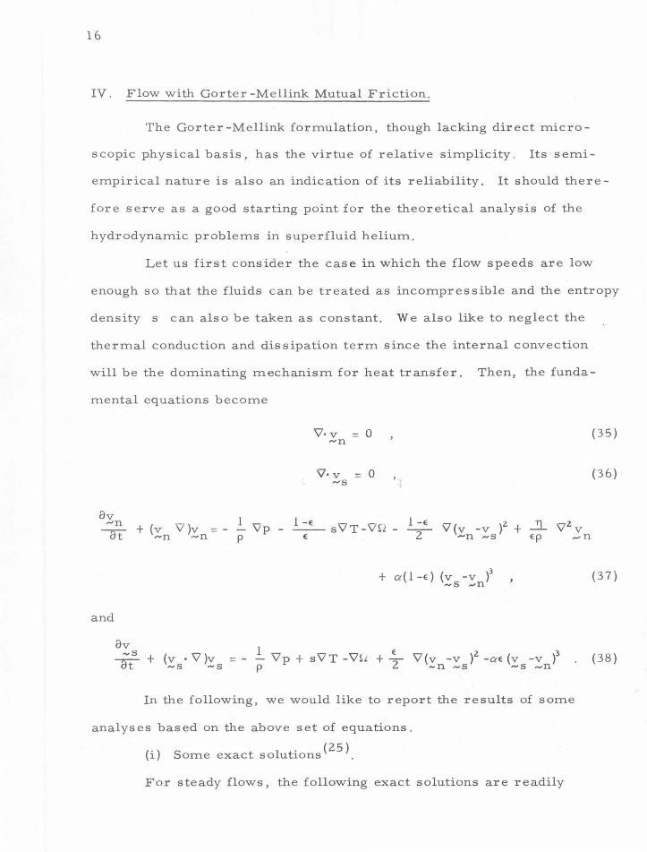
IV. Flow with Gorter -Mellink Mutual Friction.
The Gorter -Mellink formulation, though lacking direct micro-
scopic physical basis, has the virtue of relative simplicity . Its semi-
empirical nature is also an indication of its reliability. It should there-
fore serve as a good starting point for the theoretical analysis of the
hydrodynamic problems in superfluid helium.
Let us first consider the case in which the flow speeds are low
enough so that the fluids can be treated as incompressible and the entropy
density s can also be taken as constant. We also like to neglect the
thermal conduction and dissipation term since the internal convection
will be the dominating mechanism for heat transfer. Then, the funda-
mental equations become
ov 1 -n ~t + (v \7 }v = - - 'Vp
ot: ,..n "'n p
and
Y'· v = 0 "'n
'l· v = 0 .....-s
1 -E _, "r 1 -E <:7 ( }2 _21_ "2 V -£- s v T-v .2 - -2
- v v -v + v ~ -n ..... s Ep ...... n
+ a:-(1-e} (v -v }3
~s ..... n
(35}
(3 6}
( 3 7}
ov 1 _:;..!!..- + (v · \7 }v =- - Y'p + sY'T -Y'SL + .:_
2 Y'(v -v )2 -a:-E (v -v )3 (38)
ot ~s -s p -n -s ~s "'n
In the following, we would like to report the results of some
analyses based on the above set of equations.
(i) Some exact solutions (25
).
For steady flows, the following exact solutions are readily
17
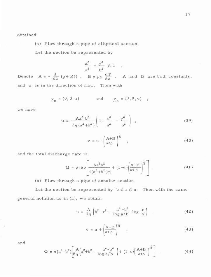
obtained:
(a) Flow through a pipe of elliptical section.
Let the section be represented by
Denote d
A = - dz (p + p~L ) , A and B are both constants,
and z is in the direction of flow. Then with
v =(O,O,u) ..... n
we have
and the total discharge rate is
and v = (O,O,v) -s
1
v = u +( A+B )3 aep
(b) Flow through a pipe of annular section.
(39)
(40)
( 41)
Let the section be represented by b <= r <= a. Then with the same
general notation as in (a), we obtain
(42)
(43)
and
(44)
18
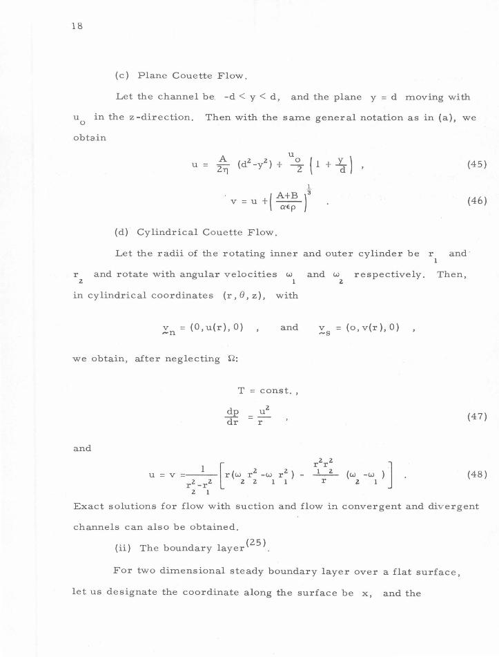
(c) Plane Couette Flow .
Let the channel be. -d < y < d, and the plane y = d moving with
u in the z-direction. Then with the same general notation as in (a), we 0
obta.in
u = A (d2 -y2) + o ( l + y )
u 2T} 2 d
1
v=u+(A+B)3 aEp
(d) Cylindrical Couette Flow.
(45)
(46)
Let the radii of the rotating inner and outer cylinder be r and · 1
r and rotate with angular velocities w and w respectively. Then, z 1 2
in cylindrical coordinates (r' e' z), with
v = (O,u(r), 0) --n
and v = (o,v(r),O) ~s
we obtain, after neglecting rl:
T = const.,
(4 7)
and
__ 1 __ [r ( w r2 -w rz ) - _r1_z_r_~_ ( w -w ) ] r2 -rz z 2 1 1 r z 1
u = v (48)
2 1
Exact solutions for flow with suction and flow in convergent and divergent
channels can also be obtained.
(ii) The boundary layer (Z 5 ).
For two dimensional steady boundary layer over a flat surface,
let us designate the coordinate along the surface be x, and the
perpendicular to the surface y. The outer flows are assumed to be
v =v = (U(x), 0) ~n -s
and in the boundary layer, let
v = (u , u ) -n x y
and v = (v , v ) -s x y
Then we have, outside the boundary layer
and
T=T 0
p + T U 2 = const .
Inside the boundary layer, we have
ou X
+u u ox X
and
ou X
ay = y
v X
ov X
ax
ou X ax+
ov ov X
+ sf 0 ox =
U dU +.2}_ dx Ep
ov + V X = yay
o2u X
+ a( 1 -e) (v -u )3
X X oyz
U dU dx
- ae(v -u )3
X X
(50)
(51)
(52)
(53)
(54)
The pressure inside the boundary layer will again be given by (50),
while the temperature variation by
(55)
If we look for similarity solutions of the form:
19
2.0
with
u =Uf'(''l) X
v = Ug'(TJ) X
TJ = _y_ h(x)
it turns out that the only permissible solutions are those with
u = a X
and h = bx (56)
which correspond to the flows in the convergent and divergent channels.
Thus although there does exist similarity solution, the varities are much
more limited than those of ordinary viscous fluids.
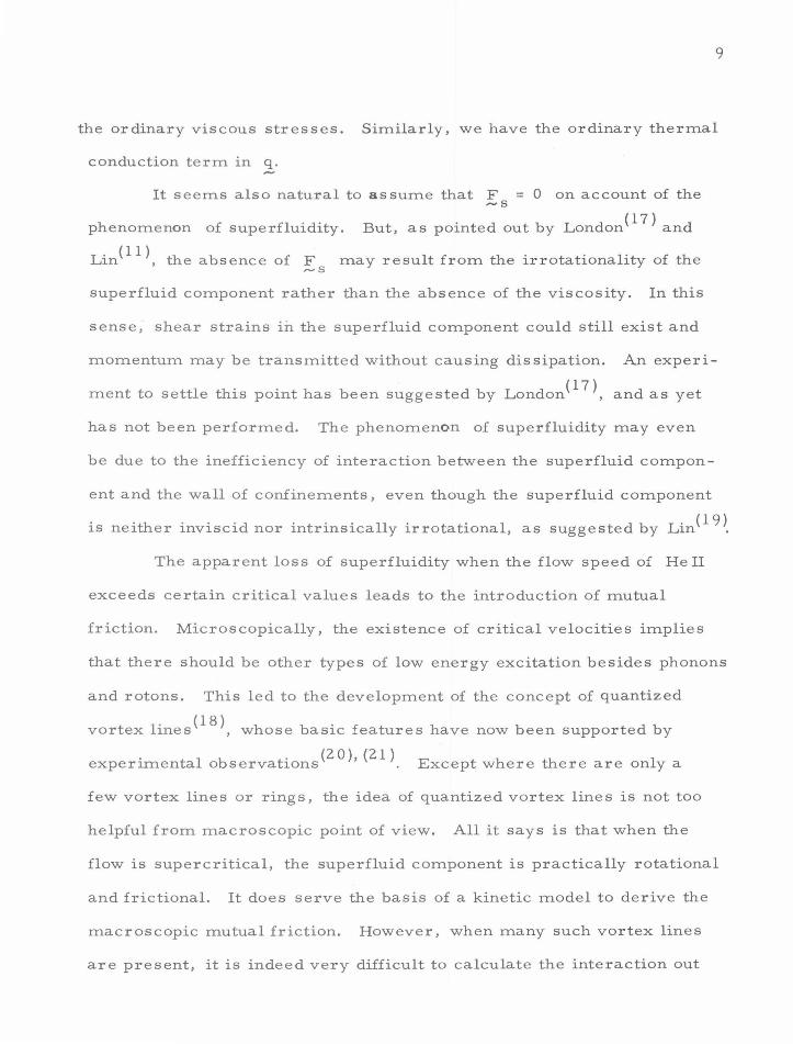
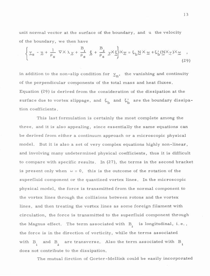
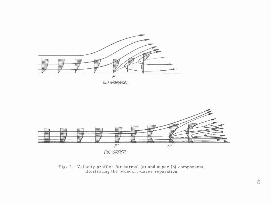
The boundary layer like that of ordinary fluids, tends to separate
when there is an adverse pressure gradient along the wall. The point of
separation for the normal component, P, is again determined by the
condition
and backflow appears downstream from P . But the appearance of this
separation point is somewhat delayed, compared with corresponding
situations for ordinary fluid flow because of the forward drag of super-
fluid component by the action of the mutual friction. The superfluid
component will slip over the surface of the wall with speed reduced
from U due to the mutual friction . A minimum in velocity profile will
appear beyond P, and eventually at a point Q, some distance from
the downstream , the streamline will divide, and backflow of the super-
fluid component will also appear beyond this point. The qualitative
picture of the flow configuration is shown in Fig. 1. Inasmuch as the
boundary layer will not remain thin once any separation occurs, the
controlling point of separation should be that of the normal component.
(iii) Stability of Flow Down an Inclined Plane(26
).
21
Let the angle that an inclined plane makes with the horizontal be
e; then the velocity fields of a fluid layer flowing under gravity g
down the plane are given by:
v = (U, 0, 0) .-n v = (V, 0, 0) s
with
and
. e } t V = U +( g Sln Q'E
where y = 0 defines the free surface, and h is the depth of the fluid
layer.
It may be shown that the stability of the flow is
long wave length disturbances. Denote R = U(o )hp / T), 0
then it is found that the flow will be unstable if
governed by the
e(U-V) R' = 2 U(o) R,
~ eR0
+ ~ (1-e)R'- 2ecot8 -2(1-e)R'(RR'}-2(1-e)(RR')cote> 0 0 0
(58)
In the limit of e ...... 1, (58) becomes
5 R
0> 4 cote (59)
while as e -+ 0, (58) becomes

22
3 R
0 > Z cote ( 60)
The essential mechanism of this type of instability is inherent in the
inviscid flow(2
?) . Viscosity only plays the role to produce the velocity
profile of the primary flow. Then it is not surprising that for both limits
E -+ 1 and E -+ 0, the Reynolds number based on the total fluid density
is the relevant parameter. Another point of interest which can be
deduced from (58) is that there exists flow configurations such that the
system is stable even for e > ;. ' i.e. when the fluid is flowing under
the plane. For He II at T = 1 . 4 °K, the situation is realizable for
-4 h ~ 10 em. This feature should have some bearing on the nature of
the film flow. Or, the study of film flow in this respect should shed
some light on the understanding of the nature of the mutual friction.
(iv) Rectified Internal Convection and Ultrasonic Cavitation (28
)
The onset of cavitation bubbles in ordinary liquids is closely
related to the phenomenom of rectified diffusion of mass into the bubble.
For He II, by far the dominating mechanism of heat transfer is the
internal convection, and since it is a convection, mass is transferred
with the heat. Then it is found that for oscillating bubbles in the liquid
helium, we have the analogous phenomenon of rectified internal con-
vection. The threshold pres sure for the cavitation can then be calculated,
and it is found, that for T > 1. 6K , yet away from TA., the thresh-
old pressure may be approximately given as
1
_ [ 1 2 ( l -E )p'Tl pt- R
0 ]
2[10o-s
EaR z 0
where p is the vapor pressure, a-, the surface tension, and R , 0
( 61 )
the
23
radius of the bubble nucleus. The results agrees fairly well with the
observation, (29 ) if R 0
is taken to be 3 x 10⁻⁴ em.
The more important problem about the nature of the cavitation
nuclei is unanswered in this investigation. Its understanding should
improve a great deal our knowledge of the superfluid as well as ordinary
liquids.
(v). Nonlinear internal convection .
The previous analyses are based on the assumption that the
temperature variation in the region of interest is not large, hence E , s,
and all the physical coefficients can be taken as constant . Since these
parameters usually vary quite sensitively with temperature, we have to
take their variation into account when the temperature variation in the
flow region is not small. Let us consider then the simplest problem that
incorporates these effects, i.e. the problem of steady one-dimensional
internal convection.
Take
v = (u(x), 0, 0) ~n
and v ~s
= (v(x), 0, 0)
and also take p as constant, and neglect the thermal conduction and
dissipation. We then obtain
su =a (62)
and
Eu + (1-E )v = constant ,
which we shall take as zero to concentrate on the aspect of internal
2'1 + s convection, and a is a constant. Denote v = then we obtain p
24
where
and
since
= G(u} + F(u} :
E [ 3u F(u} =- - + V 1 -E
G(u) =
de + s dT] du E du
~ v( 1 -E )
T = T(s )= T(u; a) and E =E (T) = e(u;a)
(63}
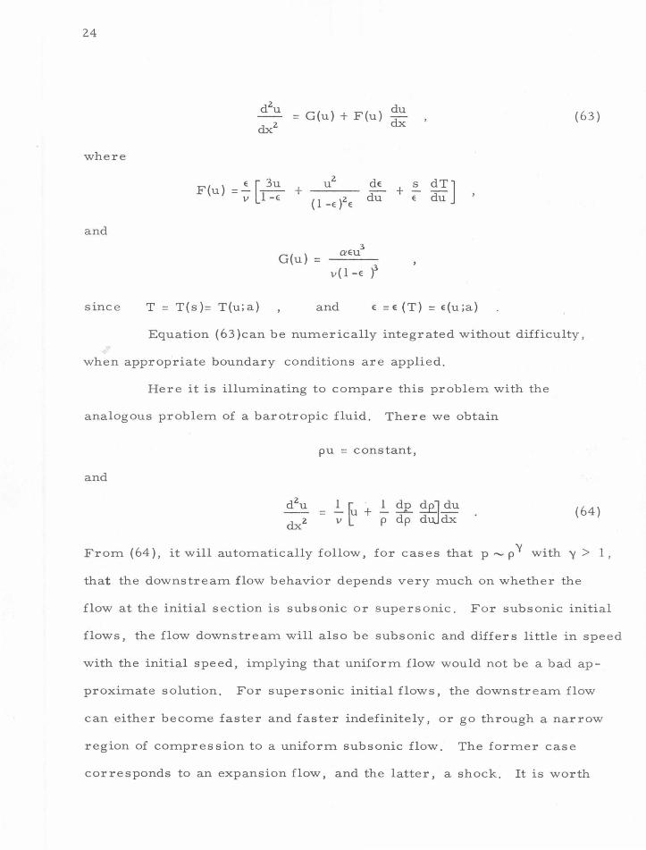
Equation (63 )can be numerically integrated without difficulty,
when appropriate boundary conditions are applied.
Here it is illuminating to compare this problem with the
analogous problem of a barotropic fluid. There we obtain
pu = constant,
and
(64)
From ( 64), it will automatically follow, for cases that p - p '{ with '{ > l ,
that the downstream flow behavior depends very much on whether the
flow at the initial section is subsonic or supersonic. For subsonic initial
flows, the flow downstream will also be subsonic and differs little in spe e d
with the initial speed, implying that uniform flow would not be a bad ap-
proximate solution. For supersonic initial flows, the downstream flow
can either become faster and faster indefinitely, or go through a narrow
region of compression to a uniform subsonic flow. The former case
corresponds to an expansion flow, and the latter, a shock. It is worth
25
noting that it comes out automatically that the shock is always compres-
sive, and the supersonic flow is always in the upstream of the stationary
shock while the subsonic flow is in the downstream.
Equation (63) is more complex than (64 ), still some qualitative
conclusion can be drawn from it. Somewhat analogous situation exists
with the replacement of sound speed by some speed L, of the order of
the speed of second sound. However, even for sub-L initial flows,
downstream flow will not remain bounded near the initial speed indefinite-
ly . This unstable feature is solely due to the presence of mutual friction.
For super -L initial flows, we also have either a downstream flow, trans-
fer ring heat faster and faster, or the appearance of shock, whose down-
str e am, however, will not stay sub-L indefinitely.
Khalatnikov(30 >, in his analysis of the progressive distortion
of finite amplitude waves into shocks, found that for barotropic fluids,
the shock will be compressive or expansive when c + p ~~ 1s positive
or not, while for He II, the temperature shock will be heating or cool
ing when ddT[ 1 :E s 2 c z] is positive or not, where c and c
2 are speeds
of sound and second sound respectively. These results are also contained
in the solutions of (63} and (64). Indeed, the reason that only compressive
shocks exist for ordinary fluid is due to the fact that we always have
c + de > 0 p dp
d [ 1 -E 2 ] The same can not be said of err -E- s cz . In fact,
for temperature above 2. 0°K and in the interval between 0 . 4 to 0. 9°K,
we have d~ [ 1 ;e s 2 c2
] < 0 . Then we should have a sub- L upstream flow
going through a stationary cooling shock to a super- L downstream flow.
The detailed experimental study of nonlinear heat transfer in different
temperature range should be very helpful to our understanding of the
26
hydrodynamics of superfluid helium .
V. Discussions and Speculations.
The uncertainty about the hydrodynamic formulation of super-
fluid helium is in part a reflection of the incompleteness of our under-
standing of the microscopic physics of the liquid helium. The prevailing
theory initiated by Landau (1 2
) can give satisfactory explanation of
phenomena only up to temperature not too close to X. -point. It fails
completely to account for the singular behavior in the X. -transition. Now,
in this theory, excitations corresponding to different parts of a single
spectrum are identified with phonons and rotons. Phonons represent the
sound waves, while the rotons, as Feynman and Cohen (31
) pointed out,
will generate flow field very much like that due to a tiny classical vortex
ring. This leads to the obvioud question: are rotons vortex rings? If
so, presumably, they are quantized vortex rings(Zl ). Then the other type
of excitation, i.e., the quantized vortex lines, may just be another aspect
of the rotons. Some very interesting features come out if we pursue along
this direction somewhat further.
We may take the view that there are two distinct types of excita-
tions, i.e. phonons, and rotons, each having its own spectrum. For
phonons, we have the dispersion relation:
E(p) = cp (65)
where p is the momentum, and c, the sound speed. While for rotons,
as suggested by the classical hydrodynamics, the dispersion relation can
be taken as(Zl):

27
( 66)
where
( 6 7)
K is the circulation, and 6 is a constant of order unity, which will
depend on the size of the vortex ring and the nature of its core. Assume
the circulations are quantized, then for He4 vvith atomic mass m, we
hav e
h _3 2 -1 K = - = 0 . 997 X 1 0 em sec
m
Most vortex rings would have only one unit of circulation, since
for the same momentum, to have two units of circulation would increase
the energy by eight-fold. Formally, for an assembly of multitudes of
phonons and rotons, the energy of a given state may be schematically
written as
( 68)
where E(p) is the energy due to phonons if no rotons are present, E(r)
that due to rotons ifnophonons are present, and E(pr), the remaining
part which may be called the phonon-rotan interaction energy . Let us
neglect E(pr) as a first approximation . In the same approximation, we
shall neglect the interactions among phonons, then
(69) . . 1 1
where n~p) is the number of phonons with momentum p .. 1 1
The expression of E(r) will not be as simple as that of E(p).
Again, from classical hydrodynamics, it is shown(3
Z) that the energy of
28
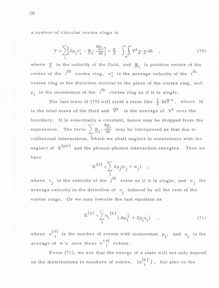
a system of circular vortex rings 1s
T = 2Izpivj_ - ~i· d~!J + T (70)
i
where y is the velocity of the fluid, and R . is position vector of the ""'1
center of the i th vortex ring' v ~ 1s the average velocity of the i th 1
vortex ring in the direction normal to the plane of the vortex ring, and
p. 1s the momentum of the ith vortex ring as if it is single. 1
The last term of (70) will yield a term like } MV 2, where M
is the total mass of the fluid and '\fl is the average of V 2 over the
boundary. It is essentially a constant, hence 1nay be dropped from the
\ dp . expression. The term L ~i · dt
1 may be interpreted as that due to
collisional interactions, \vhich we shall neglect in consistence with the
neglect of E(pr) and the phonon-phonon interaction energies. Then we
have
(r) I E = Zp.(v . +w.} J J J
J
where v. J
is the velocity of the j th roton as if it is single, and w . J
average velocity in the direction of v. induced by all the rest of the J
vortex rings. Or we may rewrite the last equation as
E (r) -I (r) .l - n. [A 2 ] 1 p. + Zp.u.
. 1 1 1 1
the
( 71 )
( r) where n . · 1s the number of rotons with momentum p., and u. is the
1 1 1
average of w's over these n ( ~) rotons. 1
From (71 ), we see that the energy of a state will not only depend
on the distributions in numbers of rotons, {n (~) } , but also on the 1
29
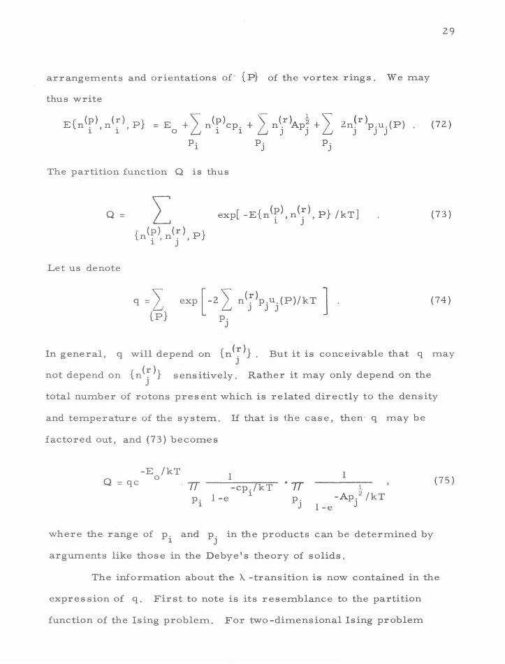
arrangements and orientations of' {P} of the vortex rings. We may
thus write
Zn(r >p. u. (P) J J J
(72)
The partition function Q is thus
Q = (7 3)
Let us denote
(74)
In general, q will depend on {n (~ )} . But it is conceivable that q may J
not depend on {n(~)} sensitively. Rather it may only depend on the J
total number of rotons present which is related directly to the density
and temperature of the system. If that is the case, then · q may be
factored out, and (73) becomes
Q = qc -E /kT
0 1 -cp. /kT
1 -e 1
1 1
-Ap.2 /kT 1 -e J
where the range of p . and p. in the products can be determined by 1 J
arguments like those in the De bye 1 s theory of solids.
(75)
The information about the A -transition is now contained in the
expression of q. First to note is its resemblance to the partition
function of the Ising problem. For two-dimensional Ising problem

30
with
E{s . } = _"\ E:s.s. 1 ~ 1 J
<ij>
wher e s. can take values either +1 or -1, <ij> denotes a nearest-1
neighbor pair of spins, and E: > 0, it is found(33
) that the specific heat
in the neighborhood of the transition temperature
with
c = 0. 4 781 c
= 0. 4945
= 0. 4991
C = -kG in I T-T I c c
for hexagonal lattice,
for square lattice,
for triangular lattice.
T is c
For liquid helium, the singular part of the specific heat per atom near
T X. is given by( 5 )
C = -0.63kin I T-Tx.l
The calculation of q of course is much more complex than the two-
dimensional Ising problem. It is a three dimensional problem with not
merely nearest neighbor interaction. Moreover, the vortex rings are
not fixed in space and their orientations are not necessarily quantized.
However, for their lowest energy configuration, the pattern may be
simply orientated and relatively stationary thus not too different from
that of Ising problem.
Within this model , the phenomenon of su.perfluidity may be
interpreted as follows. Below X. -point, there is a long range order
among roton 1 s arrangements and orientations. The disturbances from
31
any external agents tend more favorably to create new rotons rather than
change the energies and momenta of existing rotons and destroy the long
range order . Thus we have the superfluidity for flows below the critical
velocity needed to create the most easily exictable excitations, i.e. ,
the quantized vortex lines, or in our terminology, the large rotons.
Above the X. -point, no long range order exists for rotons. Thus although
new excitations could be created -by external disturbances, their
momenta and energies may be preferably spent to change the momenta
and energies of the existing rotons. Then superfluidity will disappear.
The difficulty in the calculation of q prevent us to make any
quantitative test of this model. This qualitative speculation is just the
first step towards a fuller understanding of the problem. In larger
aspects, it has long been our conviction that a successful theory of liquid
structure may be hinged on the discovery of the right elementary excita
tions just like what phonons are to solids. Thus, it may be worthwhile
to explore this idea of roton theory even for ordinary liquids.
32
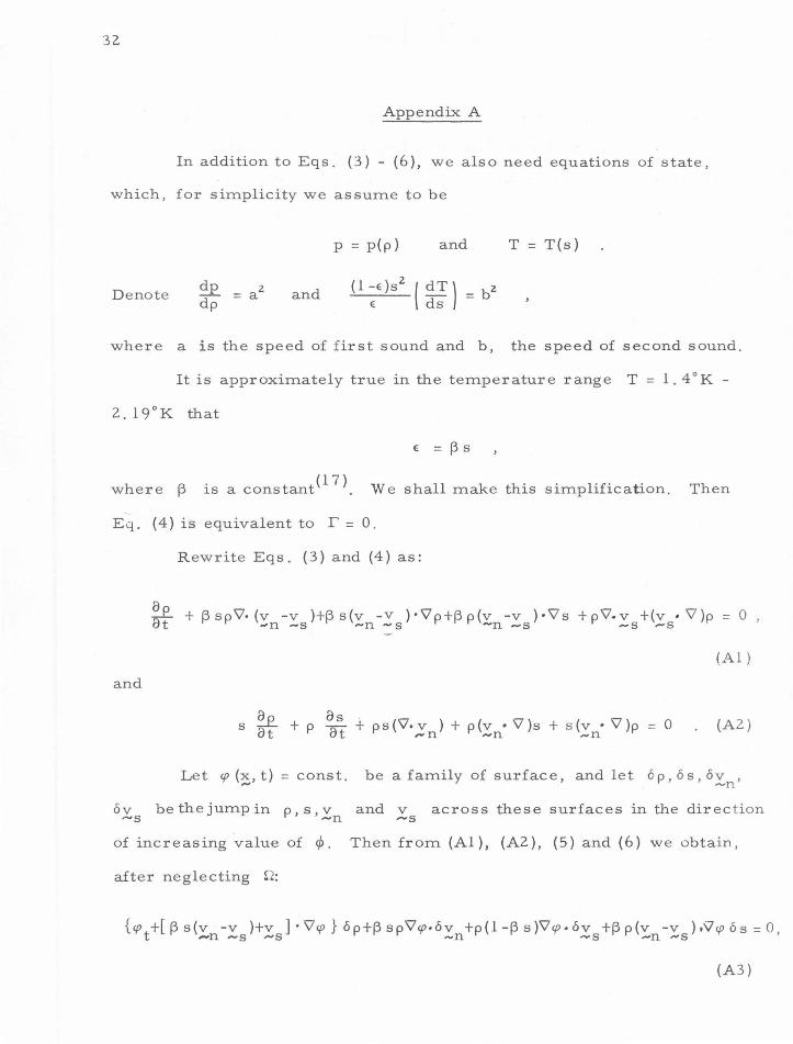
Appendix A
In addition to Eqs. (3) - (6), we also need equations of state,
which, for simplicity we assume to be
p = p(p) and T = T(s)
Denote and
where a is the speed of first sound and b, the speed of second sound.
It is approximately true in the temperature range T = 1. 4°K -
E = l3 S
where l3 1s a constant(l?}_ We shall make this simplification. Then
Eq. (4) is equivalent to r = 0.
and
6v ""'S
Rewrite Eqs. (3} and (4) as:
~ + l3spY'•(v -v )+13s(v -V )·Y'p+l3p(v -v )·Y's +pY'•v +(v ·Y')p = 0 , Bt -n -s -n -s ~n -s -s .-s
(Al )
s ~t + p a"s .j.. ps(Y'·v ) + p(v • Y')s + s(v • Y')p = 0 (A2} u ut ~n ~n -n
Let cp (~, t) = const.
be the jump in p,s,v ~n
be a family of surface, and let 6p, 6s, ov , ~n
and v .-s across these surfaces in the direc t ion
of increasing value of c/>. Then from (Al), (AZ), (5) and (6) we obtain,
after neglecting s-2:
{cpt+[13s(v -v )+v ]·Y'cp}6p+l3sp\i'cp.6v +p(l-13s)\i'cp.6v +l3p(v -v ).'i7cp6s=0, ,...n -s ,..,s -n -s ..-n .-s
(A3)
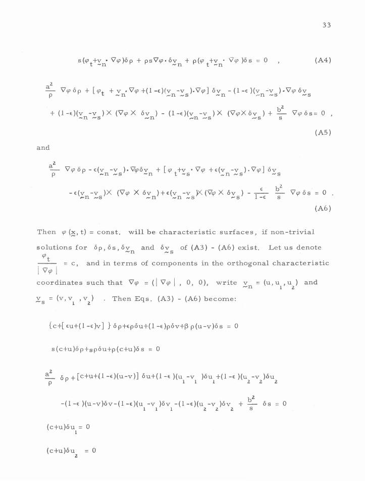
33
(A4)
b2 + (1-E}(v -v ) X (V'cp X 6v ) - (1-E}(v -v ) X ('VcpX 6v ) + 'lcp 6s= 0 ,
-n ,.....s -n .-n -s .-s s
(AS)
and
p
E. b2 -E(v -v )X (V'cp X 6v )+E(v -v )X('VcpX 6v)- -- V'cp6s = 0.
-n-s ,.....n -n-s .... s 1-E s
(A6)
Then cp (~, t) = const. will be characteristic surfaces, if non-trivial
solutions for 6 p, 6 s, 6v and 6v of (A3) - (A6) exist. Let us denote ~n ,.....s
cpt -- - c and in terms of components in the orthogonal characteristic I 'lcp I - , coordinates such that V'cp =(I V'cp I, 0, 0), write v = (u, u , u )
-n 1 2
.Ys = (v , v1
,v2
) . Then Eqs. (A3)- (A6) become:
{c+[Eu+(1-E)v] }6p+Ep6u+(l-E)p6v+~p(u-v)6s = 0
s(c+u)6p+sp6u+p(c+u)6s = 0
p 6 p + [c+u+(l-E}(u-v)] 6u+(l-E )(u -v )6u +(1-E )(u -v )6u
1 1 1 2 2 2
-(1-E }(u-v)6v-(l-e)(u -v )6v -(1-e)(u -v )6v
(c+u)6u = 0 1
(c+u)6u = 0 2
1 1 1 2 2 2 6s = 0
s
and
34
p 6p-e(u-v)6u-e(u -v )6u -e(u -v )6u +[c+v+e(u-v))6v
1 1 1 2 2 2
E b 2
+ e(u -v )6v +e(u -v )6v - -- 6s = 0 1 1 1 2 2 2 1 -E S
(c+v)6v = 0 1
(c+v)6v = 0 2
Therefore, to have non-trivial solutions for the jump quantities either
c = -u or
C + [ EU + ( 1 - E )v ] Ep
s(c+u) sp
a2 c+u+(l-e)(u-v)
p
a2 -e(u-v)
p
or
c +eu + ( 1 - e )v E
c+u 1
a2 c+u+(1-e )(u-v)
a2 -e(u-v)
or c = -v
(1 -E )p
0
-(1-e)(u-v)
_.:.e._ (u-v) s
p(c+u)
b2
s
E b2 c+v+e(u-v) · - T=e s
(1 -E) e(u-v)
0 c+u
-(1 -e)(u-v) b2
c+v+e (u-v) E
- T=e
The last determinant may be reduced to
(A7)
= 0
= 0
b2
35
c + v c + ( 1 - e )u +ev 1
az-bz (c+u)2- b 2 -(u-v) = 0
az (1 -e)(c+u)(c+v)+e(c+u)2 (c+v)
which, after expansion, becomes
c4 +c3[ 2(u+v)}t-c2
[ u 2 +v2 +4uv-a2 -b2] +c{Zuv(u+v)-2[ (1-e)u+ev] a 2 -2[ eu+(l-e)v] b 2
}
+ {u2v 2-[ (1-e)u2 +ev2
] a 2-[ eu2 +(1-e)v2
] b 2 +a2b 2}
+(u-v){c3 +c2[ (l+e)u+(Z-e)v] +c[ eu2 +(1-e )v2 +2uv-a2
] +[ eu2v+(1-e)uv2 -a2 (u-eu+ev)] }=<
(A 7)
The last term with the factor (u-v) would be absent if the terms
Y'(v -v )2 are absent in Eqs. (5) and (6). Thus the characteristic ~n -s
speeds will be different if these terms are missing. In particular, con-
sider the limiting case i . e. when the liquid can be considered
as incompressible, we obtain from (A7):
which yields 1
c = ~ { -[ (3-Ze)u+(Ze-1 )v] ±[ (1-Ze)2 (u-v)2 +4b2]"
2} . (A9)
On the other hand, when the term with the factor (u-v) in (A7) is m1ss-
ing, we obtain
1
c = -[(1-e)u+ev] ± [b2 -e(l-e)(u+v)2]
2 (Al 0)
c is always real from (A9), but c may be complex from (Al 0).
36
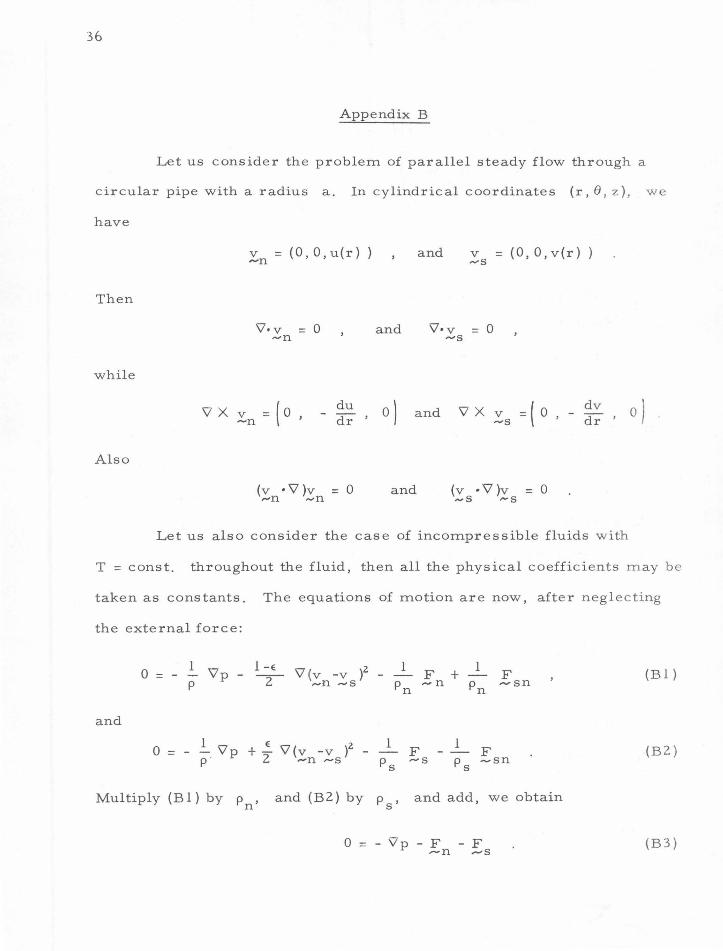
Appendix B
Let us consider the problem of parallel steady flow through a
circular pipe with a radius a. In cylindrical coordinates (r, fJ, z ), we
have
v = (O,O,u(r}) -n
Then
'V· v = 0 ,....n
while
'VXv =(o, -n du
- dr '
Also
(v • \7 )v = 0 ,...n .... n
and
and v = (0, O,v(r)) ....-s
'V·v = 0 ""S
0) and 'VXv =(o , - dv dr ..... s
and (v • \7 )v = 0 .... s ...... s
' 0) .
Let us also consider the case of incompressible fluids with
T = const. throughout the fluid, then all the physical coefficients may be
taken as constants. The equations of motion are now, after neglecting
the external force:
0 = 1 1 -E 2 1 Y'p - -
2- 'V(v -v ) -
p ...... n -s Pn F + -n
F ,..., sn (B 1)
and
1 E \7 2 1 1 0 = - - 'Vp +- (v -v ) - F F
p 2 -n -s Ps ,.....s
Ps ~sn (B2)
Multiply (B 1) by Pn' and (BZ) by p s' and add, we obtain
0 = - Vp - F - F ---n -s
(B3)
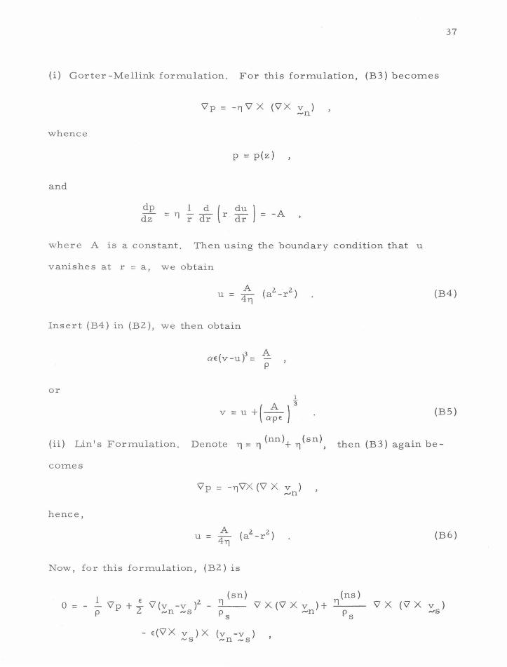
37
(i) Gorter -Mellink formulation. For this formulation, (B3) becomes
V'p = -11 \7 X (\7 X v ) -n
whence
p = p(z)
and
dp = YJ .!_ _5!_ { r du ) = -A dz r dr dr
where A is a constant. Then using the boundary condition that u
vanishes at r = a, we obtain
(B4)
Insert (B4) in (B2 ), we then obtain
or
ae(v-ui= A p
1
v = u +(~ )3
ape (B5)
(ii) Lin's Formulation. Denote 11 = 11 (nn)+ YJ(sn), then (B3) again be-
comes
V'p = -YJV'X (\7 X v ) ..... n
hence,
(B6)
Now, for this formulation, (B2) is
1 (sn) (ns)
0 = - - V'p + .:_ \7 (v -v )2 - _11 __ 'V X (\7 X v ) + YJ \7 X (V X v ) p 2 -n ""s p s .-n p s ...-s
- e(V'X v ) X (v -v ) ........ g ...... n -s
38
which in components form becomes:
and
A 0 =
p
(sn) ....:.TJ __ ,_A_ -T]
(ns) T] 1 d { dv ) r dr r dr
d dv 0 = e(u-v) dr (u-v) + e(u-v) dr
From (B8 ), we obtain
du e (u -v) dr = 0
or
u=v
which is incompatible with the boundary condition (23 ).
Also, we obtain from (B7):
0 = ~ - _1 (T](sn) p p s T]
(ns) )
~ '
or
(nn)+ (sn) ( sn) (ns) T] T] = T] -T]
p Ps
(B 7)
(B8)
(B9)
(B 10)
If the restriction that T = constant throughout the fluid is relaxed
and instead we let T = T(r), then (B8) will be changed to
d dT dv 0 = e(u-v) cir (u-v) + s dr + e(u-v) dr
Hence
du dT e(u-v) dr +s dr =0 (Bll)
which determines the radial distribution of temperature . Now from (B 7),
we obtain
v = _A.,...----r- [( 1 -E) - ~(sn) J r 2+ K 4 TJ(ns) .,
The boundary condition (2 3) will lead to,
at r =a
whence we obtain
v = A [ (sn)
4T](ns) ~
(iii) The HVBK formulation. (B3) for this case becomes
0 = -'Vp - YJ'VX ('VXv ) -A. ('VX v ) X ('VX _\:') -n -s -
Now
vx v -s
dv
( - dr
= O, 1~;1 0) -(o -sgn dv 0 )
' - ' dr ' v = I 'VX v I -s
thus
v X 1: = ( 0, 0, - ~ sgn ~; )
In components, (B15) then becomes:
and
Thus we have
op 1 d (r ddur) az = T] r dr
op ar= _ ~~dv I r dr
p = -Az +f(r)
39
(B12)
(B 13)
(B 14)
(B 15)
(B 16)
(Bl 7)
(B18)
40
and
(B 19)
For this formulation, (B2) is
0 = 1 'lp + e 'l(v -v )z.- A wX ['lX ~] - - 1- [B wX t.+B v X (w X l:.) -p 2 -n .-s - '=> '=' Ps Ps 1"" ,.., z.""' "" ,..,
Now
~X (~X f)= { 0, 0, -[ u-v] 1:; I and
In terms of components, (B20) becomes
dv J dr
and
.!.._ dv } P r dr
s
. B
0 =(~- /J; ~~:\ +e(u-v) d~ (u-v)+ p~ [(u-v) :; + p~r 1:;1]
(B20)
(B21)
(B22)
Equations (B21) and (B22) are in general incompatible. Again
let us take T = T(r), then (B22) is changed to
0 =( .!.._ - _1_ + ~) ~~ dv\ + e(u-v) ~ (u-v) + ~ (u-v) ddvr + s ddrT p p z. r dr dr p
s p s s
(B23)

41
which serves to determine the radial distribution of the temperature.
For Eq. (B21 ), we see that :; can only vanish at r = 0, and it indeed
vanishes there. dv
Hence dr does not change sign. Take A to be positive,
h dv ~ 0 we see t at dr ~ . Hence (B21) becomes
Numerical method may be used to integrate the last equation,
although series solution can be found in the neighborhood of r = 0.
However, it is worthwhile to note:
and
=
~ ~ ( dv + Ar _ ~ _1_) B p dr ZYJ p z
z s r r -+ 0
= [ A z z A r1 Jz v+- (r -a)+-
411 Ps
B Ap z
ZAps ( dv + Ar _ ~ _1_) 2
B p dr ZYJ p z z s r
Ap s ( d2v + ~ + 2 A _1_)
B p d z ZYJ p 3 + z r s r
[ A z z A 1] 2
v + - (r -a ) + - -4YJ p r s
[ A z z A 1 ]
3
v + - (r -a ) + - -411 p r
s
[ Aa
2 J v(o) - 4 T]
(B25)
(B26)
p
(a.)NO,eMAL
P' (b) StJPER
Q'
Fig. 1. Velocity profiles for normal (a) and super (b) components, illustrating the boundary-layer separation
*" N
References
(1). Kamerlingh Onnes, H. Proc. Acad. Sci. Amst . .!....!._, 168 (1908).
(2). Kamerlingh, Onnes, H. Proc. AcadSci. Amst .. ! .... ~ . .' 1903 (1911}.
(3). KamerlinghOnnes, H. andBoks, J.D.A. Commu. Phys. Lab. Univ. Leiden, No. 1706 (1924).
(4). Keesom, W. H. and Clusius, K ., Proc. Acad. Sci. Amst. 22., 307, (1932) .
(5}. Fairbank, W. M., Buckingham, M.J., and Kellers, C. F., Proc. 5th Int. Conf. Low Temp. Phys. 50 (1957).
(6). Kapitza, P. L., Nature, 141, 74 (1938}.
(7). Allen, J.F. and Misener, A.D., Nature, 141, 75 (1938}.
(8). Allen, J.F. and Jones, H., Nature, 141, 243 (1938}.
(9) . Tisza, L., Nature, 141, 913 (1938) .
(10). Daunt, J.G., and Mendelssohn, K., Nature, !43, 719 (1939).
(11}. Tisza, L., J. Phys. Radium,.!.._, 165, 350 (1940).
(12) . Landau, L. D. , J. Phys., Moscow, ~. 71 (1941 ).
(13) Peshkov, V.P., J. Phys., Moscow,~. 131, 381 (1944).
(14). Daunt, J. G., and Mendelssohn, K., Proc. Roy. Soc. A 170, 423, 439 (1939).
(15). Allen, J.F. and Misener, A.D., Proc. Roy. Soc. A 172, 467 (1939).
(16). Zilsel, P.R., Phys. Rev., 79, 309 (1950) ; 92, 1106 (1953).
(17). London, F., "Superfluids", Vol. 2. John Wiley and Sons, Ltd. New York (1954).
(18). Feynman, R. P. in "Progress in Low Temperature Physics" (C. J. Gorter ed.) Vol. I, Chap. II, North Holland, Amsterdam (1955).
(19). Lin, C. C., in "Liquid Helium" (G. Careri ed.) pp . 93-146, Academic Press, New York (1963 ).
(20). Hall, H. E. and Vinan, W.F., Proc. Roy. Soc. A, 238, 204, 215 (1956). -
(21}. Rayfield, G. W. and Rei£ F., Phys. Rev. 136, A1194 (1964).
(22). Gorter, C. J. and Mellink, J. H., Physica .!..2_, 285 (1949).
(23). Hall, H. E. Adv. in Phys., 2_! 89 (1960).
(24 ). Bekarevitch , I. and Khalatnikov, I. M. , Soviet Phys. JETP .! .... ~ . .' 643 (1961 ).
(25 ). Hsieh, D. Y. , Section Report No. 327-3. Jet Propulsion Laboratory, California Institute of Technology. (1966).
(26). Hsieh, D. Y., Phys. Fluids]_, 1755 (1964).
(27). Heish, D. Y., Phys. Fluids, ~. 1785 (1965).
(28). Hsieh, D. Y., "Rectified Internal Convection and Ultrasonic Cavitation in Helium II", Report No. 85-33, Division of Engineering and Applied Science ,- Calif. Inst. of Tech. ( 1966 ).
(29). Finch, R. D., Kagiwada, R., Barmatz, M., and Rudnick, I., Phys. Rev. 134, Al425, (1964).
(30). Khalatnikov, I. M., "Introduction to the Theory of Superfluidity", W.A. Benjamin, Inc. NewYork(1965).
(31). Feynman, R. P. and Cohen, M., Phys. Rev., 102, 1189 (1956).
(32 ). Thomson, J. J., "A Treatise on the Motion of Vortex Rings", MacMillan and Co., London, (1883).
(33). Houtappel, R. M. F., Physica, ~. 425 (1950).
DISTRIBUTION LIST FOR UNCLASSIFIED TECHNICAL REPORTS ISSUED UNDER
Contract N00014-67 -0094-0009
Single Copies Unless Otherwise Given
Chief of Naval Research Department of the Navy Washington 25, D. C. Attn: Codes 438 ( 3)
461 463 429
Commanding Officer Office of Naval Research, Branch Office 495 Summer Street Boston 10, Massachusetts
Commanding Officer Office of Naval Research, Branch Office 219 South Dearborn Street Chicago, Illinois 60604
Commanding Officer Office of Naval Research, Branch Office 207 West 24th Street New York 11, New York
Commanding Officer Office of Naval Research, Branch Office 1030 East Green Street Pasadena, California
Commanding Officer Office of Naval Research, Branch Office Box 39 Fleet Post Office New York, New York (25)
Director Naval Research Laboratory Washington 25, D. C. Attn: Codes 2000
2020 2027 (6)
Chief,Bureau of Yards and Docks Department of the Navy Washington 25, D. C. Attn: Codes D- 202
Commander
D-400 D-500
Naval Ordnance Laboratory Silver Spring, Maryland Attn: Dr. A. May
Desk DA Desk HL Desk DR
Chief, Bureau of Ships Departm~nt of the Navy Washington 25, D. C. Attn: Codes 300
305 335 3-11 342A 345 421 440 442 634A
Chief, Bureau of Naval Weapons Department of the Navy Washington 25, D. C. Attn: Codes R
R-12 RR RRRE RU RUTO
Commanding Officer and Director David Taylor Model Basin Washington 7, D. C. Attn: Codes 142
Commander
500 513 521 526 550 563 589
Naval Ordnance Test Station China Lake, California Attn: Codes %1·4 J. W. Hicks
4032 753
Superintendent U. S. Naval Academy Annapolis, Maryland Attn: Library
Hydrographer U. S. Navy Hydrographic Office Washington 25, D. C.
Commanding Officer and Director U. S. Navy Engineering Laboratory Annapolis, Maryland Attn: Code 750
Commander U. S. Naval Weapons Laboratory Dahlgren, Virginia Attn: Technical Library Division
Computation and Exterior Ballistics Laboratory (Dr. Hershey)
Commanding Officer . NROTC and Naval Administration Un1t Massachusetts Institute of Technology Cambri dge 39, Mass.
Commanding Officer and Director Underwater Sound Laboratory Fort Trumbull New London, Connecticut Attn: Technical Library
Commanding Officer and Director U. S . Navy Mine Defense Laboratory Panama City, Florida
Superintendent U.S. Naval Postgraduate School Monterey, California Attn: Library
Commanding Officer and Director Naval Electronic Laboratory San Diego 52, California Attn: Code 4223
Commanding Officer and Director U. S. Naval Civil Engineering Laboratory Port Hueneme, California
Commanding Officer and Director U. S. Naval Applied Science Laboratory Flushing and Washington Avenues Brooklyn, New York 11251 Attn: Code 937
Commander Norfolk Naval Shipyard Portsmouth, Virginia
Commander U. S. Naval Ordnance Test Station Pasadena Annex 3202 East Foothill Boulevard Pasadena, California Attn: Dr. J. W. Hoyt
Research Division P508 P804 P807 P80962 (Library Section)
Commander New York Naval Shipyard Naval Base Brooklyn, New York
Commander Boston Naval Shipyard Boston 29, Massachusetts
Commander Philadelphia Naval Shipyard Naval Base Philadelphia 12, Pennsylvania
Commander Portsmouth Naval Shipyard Portsmouth, New Hampshire Attn: Design Division
Commander Charleston Naval Shipyard U. S. Naval Base Charleston, South Carolina
Commanding Officer U. S. Naval Underwater Ordnance Station Newport, Rhode Island Attn: Research Division
Commander Long Beach Naval Shipyard Long Beach 2, California
Commander Pearl Harbor Naval Shipyard NavyNo. 128, FleetPostOffice San Francisco, California Shipyard Technical Library'. Code 130L7 San Francisco Bay Naval Sh1pyard, Bldg. 746 Vallejo, Calif. 94592
Superintendent U. S. Merchant Marine Academy Kings Point Long Island, New York Attn: Department of Engineering
Commandant U. S. Coast G1..1ard 1300 E Street, NW Washington, D. C.
Beach Erosion Board U. S. Army Corps of Engineers Washington 25, D. C.
Commanding Officer U. S. Army Research Office Box CM, Duke Station Durham, North Carolina
Commander Headquarters, U. S. Army Transportation
Research and Development Comm. Transportation Corps Fort Eustis, Virginia
Director U. S. Army Engineering Research and
Development Laboratories Fort Belvoir, Virginia Attn: Technical Documents Center
Scientific and Technical Division Library of Congress Washington, D. C. 20540
Defense Documentation Center Cameron Station Alexandria, Virginia ( 1 0)
Maritime Administration 441 G Street, NW Washington 25, D. C. Attn: Coordinator of Research
Division of Ship Design
Fluid Mechanics Section National Bureau of Standards Washington 25, D. C. Attn: Dr. G. B. Schubauer
U. S. Atomic Energy Commission Technical Information Service Extention F. 0. Box 62 Oakridge, Tennessee
Director of Research Code RR, NASA 600 Independence Avenue, SW Washington, D. C. 20546
Director Langley Research Center National Aeronautics and Space Adm. Langley Field, Virginia
Director Ames Research Laboratory National Aeronautics and Space Adm. Moffett Field, California
Director Lewis Research Center National Aeronautics and Space Adm. Cleveland, Ohio
Director Engineering Science Division National Science Foundation Washington, D. C.
Air Force Office of Scientific Research Mechanics Division Washington 25, D. C.
Aeronautical Library National Research Council Montreal Road Ottawa 7, Ontario, Canada
Engineering Societies Library 29 West 39th Street New York 18, New York
Society of Naval Architects and Marine Engineers
74 Trinity Place New York 6, New York
Webb Institute of Naval Architecture Glenn Cove, Long Island, New York Attn: Professor E. V. Lewis
Technical Library
The Johns Hopkins University Baltimore 18, Maryland Attn: ProfessorS. Corrsin
Professor F. H. Clauser Professor 0. M. Phillips
Director Applied Physics Laboratory The Johns Hopkins University 8621 Georgia Avenue Silver Spring, Maryland
New York State University Maritime College Engineering Department Fort Schuyler, New York Attn: Professor J. J. Foody
California Institute of Technology Pasadena, California 91109 Attn: Hydrodynamics Laboratory
Professor T. Y. Wu Professor A. Ellis Professor A. Acosta
University of California Berkeley 4, California Attn: Department of Engineer
Professor H. A. Schade Professor J. Johnson Professor J. V. Wehausen Professor E. V. Laitone Professor P. Lieber Professor M. Holt
University of California Los Angeles, California Attn: Professor R. W. Leonard
Professor A. Powell
Director Scripps Institute of Oceanography University of California La Jolla, California
Harvard University Cambridge 38, Massachusetts Attn: Professor G. Birkhoff
ProfessorS. Goldstein

Iowa Institute of Hydraulic Research State University of Iowa Iowa City, Iowa Attn: Professor H. Rouse
Professor L. Landweber Professor P. G. Hubbard
University of Michigan Ann Arbor, Michigan Attn: Engineering Research Institute
Director Ordnance Research Laboratory Pennsylvania State University University Park, Pennsylvania Attn: Dr. G. F. Wislicenus
Director St. Anthony Falls Hydraulics Laboratory University of Minnesota Minneapolis 14, Minnesota Attn: Mr. J. N. Wetzel
Professor B. Silberman Dr. J. F. Ripkin
Massachusetts Institute of Technology Cambridge 39, Massachusetts Attn: Professor P. Mandel
Professor M. A. Abkowitz
Institute for Fluid Mechanics and Applied Mathematics
University of Maryland College Park, Maryland Attn: Professor J. M. Burgers
Cornell Aeronautical Laboratory Buffalo 21, N. Y. Attn: Mr. W. F. Milliken, Jr.
Brown University Providence 12, Rhode Island Attn: Professor Fred Bisshopp
Dr. W. H. Reid
Stevens Institute of Technology Davidson Laboratory Hoboken, New J ers·ey Attn: Mr. D. Savitsky
Mr. J. P. Breslin Dr. D. N. Hu Dr. S. J. Lukasik
Director Woods Hole Oceanographic Institute Woods Hole, Massachusetts
Director Alden Hydraulic Laboratory Worcester Polytechnic Institute Worcester, Massachusetts
Stanford University Stanford, California Attn: Dr. Byrne Perry
Dr. L. I. Schiff Dr. S. Kline Dr. E. Y. Hsu
Department of Theoretical and Applied Mechanics
College of Engineering University of Illinois Urbana, Illinois Attn: Dr. J. M. Robertson
Department of Mathematics Rensselaer Polytechnic Institute Troy, New York Attn: Professor R. C. DiPrima
Southwest Research Institute 8500 Culebra Road San Antonio 6, Texas Attn: Dr. H. N. Abramson
Department of Aeronautical Engineering University of Colorado Boulder, Colorado Attn: Professor M. S. Uberoi
Hamburgische Schiffbau- Versuchsanstalt Bramfelder Strasse 164 Hamburg 33, Germany Attn: Dr. 0. Grim
Max-Planck Institut fur Stromungsforschun1 Bottingerstrasse 6-8 Gottingen, Germany Attn: Dr. H. Reichardt, Director
Prof. Dr. -Ing. S. Schuster, Baudirector Versuchsanstalt fur Wasserbau
und Schiffbau Berlin, Germar.y
Netherlands Ship Model Basin Wageningen, The Netherlands Attn: Ir. R. Wereldsma
Dr. J . B . vanManen
Mitsubishi Shipbuilding and Engineering Company
Nagasaki, Japan Attn: Dr. K. Taniguchi
Mr. W. R. Wiberg, Chief Marine Performance Staff The Boeing Company, Aero-Space Div. P. 0. Box 3707 Seattle 24, Washington
Mr. William P. Carl Grumman Aircraft Corp. Bethpage, Long Island, New York
Mr. G. W. Paper ASW and Ocean Systems Department Lockheed Aircraft Corp. Burbank, California
Dr. A. Ritter Therm Advanced Research Division Therm, Incorporated Ithaca, New York
Hydronautics, Incorporated Pindell School Road Howard County Laurel Maryland Attn: Mr. P. Eisenberg, President
Mr. M. P. Tulin, Vice-President
Dr. J. Kotik Technical Research Group, Inc. Route 110 Melville, New York
Hydrodynamics Laboratory Convair San Diego 12, California Attn: Mr. R. H. Oversmith
Baker Manufacturing Company Evansville, Wisconsin
Gibbs and Cox, Inc. Technical Information Control Section 21 West Street New York, New York
Electric Boat Division
10006
General Dynamics Corporation Groton, Connecticut Attn: Mr. R. McCandliss
Armour Research Foundation Illinois Institute of Technology Chicago 16, Illinois Attn: Library
Missile Development Division North American Aviation, Inc. Downey, California Attn : Dr. E. R. Van Driest
National Physical Laboratory Teddington, Middlesex, England Attn: Head Aerodynamics Division
Mr. A. Silverleaf
Aerojet General Corporation 6352 Irwindale Avenue Azusa, California Attn: Mr. C. A. Gangwer
Transportation Technical Research Institute
No. 1057-1-Chome Mejiro-machi, Toshima-ku Tokyo-to, Japan
Oceanics, Incorporated Plainview, Long Island, New York Attn: Dr. Paul Kaplan
Professor C. S. Yih University of Michigan Ann Arbor, Michigan
Grumman Aircraft Corporation Bethpage, Long Island, New York Attn: Engineering Library, Plant 5
Mr. Leo Geyer
Professor J. William Ho11 Garfield Thomas Water Tunnel Ordnance Research Laboratory The Pennsylvania State University P. 0. Box 30, State Co11ege, Penn.
Professor George Carrier Harvard University Cambridge 38, Massachusetts·
Dr. E. R. G. Eckert Mechanical Engineering Department University of Minnesota Minneapolis, Minnesota 55455
Dr. Paul Garabedian Courant Institute of Mathematical Sciences New York University New York, New York
Dr. Blaine Parkin, Manager Aerospace Technology General Dynamics/Convair P. 0. Box 1950, San Diego, California
Dr. I. S. Pearsa11 National Engineering Laboratory Glasgow, Scotland
Dr. Robert Hickling, Senior Res. Engineer Mechanical Development Department Research Labs., General Motors Corp. General Motors Technical Center I 2 Mile and Mound Roads Warren, Michigan 48090
Utah State University Library Serial Department Logan, Utah 84321
Dr. James W. Daily, Chairman Department of Engineering Mechanics College of Engineering The University of Michigan Ann Arbor, Michigan 48104

Commander San Francisco Naval Shipyard San Francisco 24, California
Unclassified Security Classification
DOCUMEHTCOHTROLDATA·R&D (Security claeellication ol title, body of abstract and inde1ting Bnnotation must be entered wflen the overall r'!port is classified)
1. O~tGtNATtN G ACTtvt:Y (Corporate author) z .. . REPORT SECURITY C L"SSIFIC ... TION
Unclassified California Institute of Technology z b . CO ROUP
Division of Engineering and Applied Science Not applicable 3 . REPORT TITLE
SOME HYDRODYNAMIC ASPECTS OF SUPERFilliD HELIUM
4 . DESCRIPTIVE NOTES (Type ol report and inclusive dates)
S. AUTHOR(S) (Last name. lirttt name, initial)
Hsieh, Din-Yu
6 . REPORT OA TE 1•· TOTAL NO . OF PACOES 17b. NO. OF REFS
December 1965 42 33 Sa . CONTRACT OR <ORANT NO. 9a. ORIGINATOR'S REPORT NUMBER(S)
N00014-67-0094-0009 b . PROJECT NO . Report No. 85-36
c. 9b. OTHER REPORT lhla report)
No(S) (Any other numbers lhat may be aeaiQned
d.
10. AVAILABILITY/LIMITATION NOTICES
DISTRIBUTION OF THIS DOCUMENT IS UNLIMITED
\\. SUPPL EhiENTARY NOTES 12. SPONSORING MILITARY ACTIVITY
Office of Naval Research
13. ABSTRACT
A brief critical survey on the hydrodynamic formulations of the super-fluid helium is given first. For the irreversible process, three major formula-tions, i.e. those due to Gorter -Mellink, Lin, and Hall- Vinen, Bekarevitch-Khalatnikov, are de scribed, discussed and compared. Then some results of analyses based on the Gorter -Mellink formulation are presented. The paper concludes with some interesting findings resulting from the assumption that rotons are vortex rings.
DD FORM 1 JAN 84 1473 0101·807-6800 Unclassified
Unclassified Security Classification
14-KEY WORDS
Low temperature physics
Superfluid hydrodynamics
LINK A
ROLE
LINK B LINK C
WT ROLE WT ROLE WT
INSTRUCTIONS
\. ORIGINATING ACTIVITY: Enter the name and address of the contractor, subcontractor, grantee, Department of Defense activity or other organization (c01porate author) issuing the report.
2a. REPORT SECURITY CLASSIFICATION: Enter the overall security classification of the report. Indicate whether "Restricted Data" is included. Marking is to be in accordance with appropriate security regulations.
2b. GROUP: Automatic downgrading is specified in DoD Directive 5200.10 and Armed Forces Industrial Manual. Enter the group number. Also, when applicable, show that optional markings have been used for Group 3 and Group 4 as authorized.
3. REPORT TITLE: Enter the complete report title in all capital letters. Titles in all cases should be unclassified. If a meaningful title cannot be selected without classification, show title classification in all capitals in parenthesis immediately following the title.
4. DESCRIPTIVE NOTES: If appropriate, enter the type of report, e. g., interim, progress, summary, annual, or final. Give the inclusive dates when a specific reporting period is covered.
5. AUTHOR(S): Enter the name(s) of outhor(s) as shown on or in the report. Entet· last name, first name, middle initial. If military, show rank and branch of service. The name of the principal author is an ahsolute minimum requirement.
6. REPORT DATE: Enter the date of the report as day, month, year; or month, year. If more than one date appears on the report, use date of publication.
7a. TOTAL NUMBER OF PAGES: The total page count should follow normal pagination procedures, i.e., enter the number of pages containing information.
7b. NUMBER OF REFERENCES: Enter the total number of references cited in the report.
Sa. CONTRACT OR GRANT NUMBER: If appropriate, enter the applicable number of the contract or grant under which the report was written.
8b, Be, & Sd. PROJECT NUMBER: Enter the appropriate military department identification, such as project number, subproject number, system numbers, task number, etc.
9a. ORIGINATOR'S REPORT NUMBER(S): Enter the offi· cial report number by which the document will be identified and controlled by the originating activity. This number must be unique to this report.
9b. OTHER REPORT NUMBER(S): If the report has been assigned any other report numbers (either by the originator or by the sponsor), also enter this number(s).
10. AVAILABILITY/LIMITATION NOTICES: Enter any limitations on further dissemination of the report, other than those
imposed by security classification, using standard statements such as:
( 1) "Qualified requesters may obtain copies -of this report from DDC."
(2) "Foreign announcement and dissemination of this report. by DDC is not authorized."
(3) "U. S. Government agencies may obtain copies of this report directly from DDC. Other qualified DDC users shall request through
(4) "U. S. military agencies may obtain copies of this report directly from DDC. Other qualified users shall request through
(5) "AU distribution of this report is controlled. Qualified DDC users shall request through
If the report has been furnished to the Office of Technics Services, Department of Commerce, for sale to the public, in< cate this fact and enter the price, if known.
11. SUPPLEMENTARY NOTES: Use for additional explana· tory notes.
12. SPONSORING MILITARY ACTIVITY: Enter the name ol the departmental project office or laboratory sponsoring (paying for) the research and development. Include address.
13. ABSTRACT: Enter an abstract giving a brief and factua summary of the document indicative of the report, even thoug it may also appear elsewhere in the body of the technical report. If additional space is required, a continuation she et sh be attached.
It is highly desirable that the abstract of classified repc be unclassified. Each paragraph of the abstract shall end wi an indication of the military security classification of the in· formation in the paragraph, represented as (TS) , (S) , (C) , or (
There is no limitation on the length of the abstract. Ho• ever, the suggested length is from 150 to 225 words .
14. KEY WORDS: Key words are technical.ty meaningful ten or short phrases that characterize a report and may be used s index entries for cataloging the report. Key words must be selected so that no security classification is required. Idenl fiers, such as equipment model designation, trade name, mili project code name, geographic location; may be used as key words but will be followed by an indication of technical context. The assignment of links, rales, and weights is options
Unclassified