Embed Size (px)
Citation preview

INTRODUCTION Information contained herein is current at date of publication. As a result of improvements,
some numerical values and illustrations contained in this publication may not correspond to the
factual specification of the machine supplied to the user. The manufacturer reserves the right to
introduce design changes in machines produced that facilitate operation and improve the quality
of their work, without making minor amendments to this Operator's Manual.
This Operator's Manual is an integral part of the machine's documentation. Before using the
machine, the user must carefully read this Operator's Manual and observe all
recommendations. This guarantees safe operation and ensures malfunction free work of the
machine. The machine is designed to meet obligatory standards, documents and legal
regulations currently in force.
The Operator's Manual describes the basic principles of safety in use and operation of the
Pronar T653 agricultural trailer, which may be produced in one of three variants:
• T653 – no wall extensions,
• T653/1 – no wall extensions or with 0.5 m load box wall extensions,
• T653/2 – no wall extensions or with 0.5 m load box wall extensions,
If the information contained in the Operator's Manual needs clarification then the user should
refer for assistance to the sale point where the machine was purchased or to the Manufacturer.
MANUFACTURER'S ADDRESS:
PRONAR Sp. z o.o.
ul. Mickiewicza 101A
17-210 Narew
CONTACT TELEPHONES
+48 085 681 63 29 +48 085 681 64 29
+48 085 681 63 81 +48 085 681 63 82
SYMBOLS APPEARING IN THIS OPERATOR'S MANUAL
Information, descriptions of danger and precautions and also recommendations and prohibitions
associated with user safety instructions are marked:
and also preceded by the word "DANGER”. Failure to observe the instructions may endanger
the machine operator's or other person's health or life.
Particularly important information and instructions, the observance of which is essential, are
distinguished in the text by the sign:
and also preceded by the word "ATTENTION". Failure to observe the instructions may lead to
damage to the machine as a result of improper operation, adjustment or use.
In order to focus the user's attention on the need to perform maintenance, the relevant section
of the Operator's Manual is marked with the pictogram:
Additional tips and advice for machine operation are marked:
and also preceded by the word „TIP”.
DIRECTIONS USED IN THIS OPERATOR'S MANUAL
Left side – side to the left hand of the operator facing in the direction of machine's forward
travel.
Right side – side to the right hand of the operator facing in the direction of machine's forward
travel.
REQUIRED SERVICE ACTIONS
Service actions described in the manual are marked:
Result of service/adjustment actions or comments concerning the performance of actions are
marked:

TABLE OF CONTENTS
1 BASIC INFORMATION 1.1
1.1 IDENTIFICATION 1.2
1.1.1 TRAILER IDENTIFICATION 1.2
1.1.2 AXLE IDENTIFICATION 1.3
1.1.3 LIST OF FACTORY NUMBERS 1.4
1.2 PROPER USE 1.4
1.3 OPTIONAL EQUIPMENT 1.8
1.4 WARRANTY TERMS 1.10
1.5 TRANSPORT 1.11
1.5.1 TRANSPORT ON VEHICLE. 1.11
1.5.2 INDEPENDENT TRANSPORT BY THE USER. 1.13
1.6 ENVIRONMENTAL HAZARDS 1.14
1.7 WITHDRAWAL FROM USE 1.15
2 SAFETY IN USE 2.1
2.1 BASIC SAFETY RULES 2.2
2.1.1 USE OF TRAILER 2.2
2.1.2 HITCHING AND DISCONNECTING FROM TRACTOR 2.3
2.1.3 COUPLING AND UNCOUPLING SECOND TRAILER 2.3
2.1.4 HYDRAULIC AND PNEUMATIC SYSTEMS 2.4
2.1.5 LOADING AND UNLOADING 2.5
2.1.6 TRANSPORTING THE MACHINE 2.7
2.1.7 TYRES 2.10
2.1.8 MAINTENANCE 2.11
2.2 DESCRIPTION OF MINIMAL RISK 2.13
2.3 INFORMATION AND WARNING DECALS 2.14

3 DESIGN AND OPERATION 3.1
3.1 TECHNICAL SPECIFICATION 3.2
3.2 TRAILER CONSTRUCTION 3.3
3.2.1 CHASSIS 3.3
3.2.2 LOAD BOX 3.5
3.2.3 NET EXTENSIONS 3.7
3.2.4 MAIN BRAKE 3.8
3.2.5 HYDRAULIC TIPPER SYSTEM 3.13
3.2.6 PARKING BRAKE 3.15
3.2.7 LIGHTING SYSTEM 3.16
4 CORRECT USE 4.1
4.1 PREPARING FOR WORK BEFORE FIRST USE 4.2
4.1.1 CHECKING THE TRAILER AFTER DELIVERY 4.2
4.1.2 PREPARE A TRAILER FOR FIRST HITCHING TO TRACTOR 4.3
4.2 HITCHING AND DISCONNECTING FROM TRACTOR 4.4
4.3 COUPLING AND UNCOUPLING SECOND TRAILER 4.9
4.4 LOADING AND SECURING LOAD 4.11
4.4.1 GENERAL INFORMATION CONCERNING LOAD 4.11
4.5 TRANSPORTING LOADS 4.19
4.6 UNLOADING 4.21
4.7 PROPER USE AND MAINTENANCE OF TYRES 4.25
5 TECHNICAL OPERATION 5.1
5.1 PRELIMINARY INFORMATION 5.2
5.2 SERVICING BRAKES AND AXLES 5.2
5.2.1 PRELIMINARY INFORMATION 5.2
5.2.2 INITIAL INSPECTION OF AXLE BRAKES, 5.3
5.2.3 CHECK WHEEL AXLE BEARINGS LOOSENESS 5.4
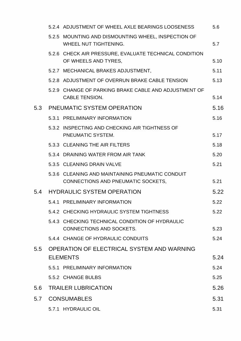
5.2.4 ADJUSTMENT OF WHEEL AXLE BEARINGS LOOSENESS 5.6
5.2.5 MOUNTING AND DISMOUNTING WHEEL, INSPECTION OF WHEEL NUT TIGHTENING. 5.7
5.2.6 CHECK AIR PRESSURE, EVALUATE TECHNICAL CONDITION OF WHEELS AND TYRES, 5.10
5.2.7 MECHANICAL BRAKES ADJUSTMENT, 5.11
5.2.8 ADJUSTMENT OF OVERRUN BRAKE CABLE TENSION 5.13
5.2.9 CHANGE OF PARKING BRAKE CABLE AND ADJUSTMENT OF CABLE TENSION. 5.14
5.3 PNEUMATIC SYSTEM OPERATION 5.16
5.3.1 PRELIMINARY INFORMATION 5.16
5.3.2 INSPECTING AND CHECKING AIR TIGHTNESS OF PNEUMATIC SYSTEM. 5.17
5.3.3 CLEANING THE AIR FILTERS 5.18
5.3.4 DRAINING WATER FROM AIR TANK 5.20
5.3.5 CLEANING DRAIN VALVE 5.21
5.3.6 CLEANING AND MAINTAINING PNEUMATIC CONDUIT CONNECTIONS AND PNEUMATIC SOCKETS, 5.21
5.4 HYDRAULIC SYSTEM OPERATION 5.22
5.4.1 PRELIMINARY INFORMATION 5.22
5.4.2 CHECKING HYDRAULIC SYSTEM TIGHTNESS 5.22
5.4.3 CHECKING TECHNICAL CONDITION OF HYDRAULIC CONNECTIONS AND SOCKETS. 5.23
5.4.4 CHANGE OF HYDRAULIC CONDUITS 5.24
5.5 OPERATION OF ELECTRICAL SYSTEM AND WARNING ELEMENTS 5.24
5.5.1 PRELIMINARY INFORMATION 5.24
5.5.2 CHANGE BULBS 5.25
5.6 TRAILER LUBRICATION 5.26
5.7 CONSUMABLES 5.31
5.7.1 HYDRAULIC OIL 5.31

5.7.2 RECOMMENDED GREASE 5.32
5.8 CLEANING TRAILER 5.32
5.9 STORAGE 5.34
5.10 TIGHTENING TORQUE FOR NUT AND BOLT CONNECTIONS 5.35
5.11 INSTALLATION AND DISASSEMBLY OF THE FRAME AND TARPAULIN COVER 5.36
5.12 INSTALLATION AND DISASSEMBLY OF EXTENSION WALLS 5.38
5.13 ADJUSTMENT OF DRAWBAR POSITION 5.39
5.14 TROUBLESHOOTING 5.39


SECTION
1
BASIC INFORMATION
Pronar T653 T653/1 T653/2 SECTION 1
1.2
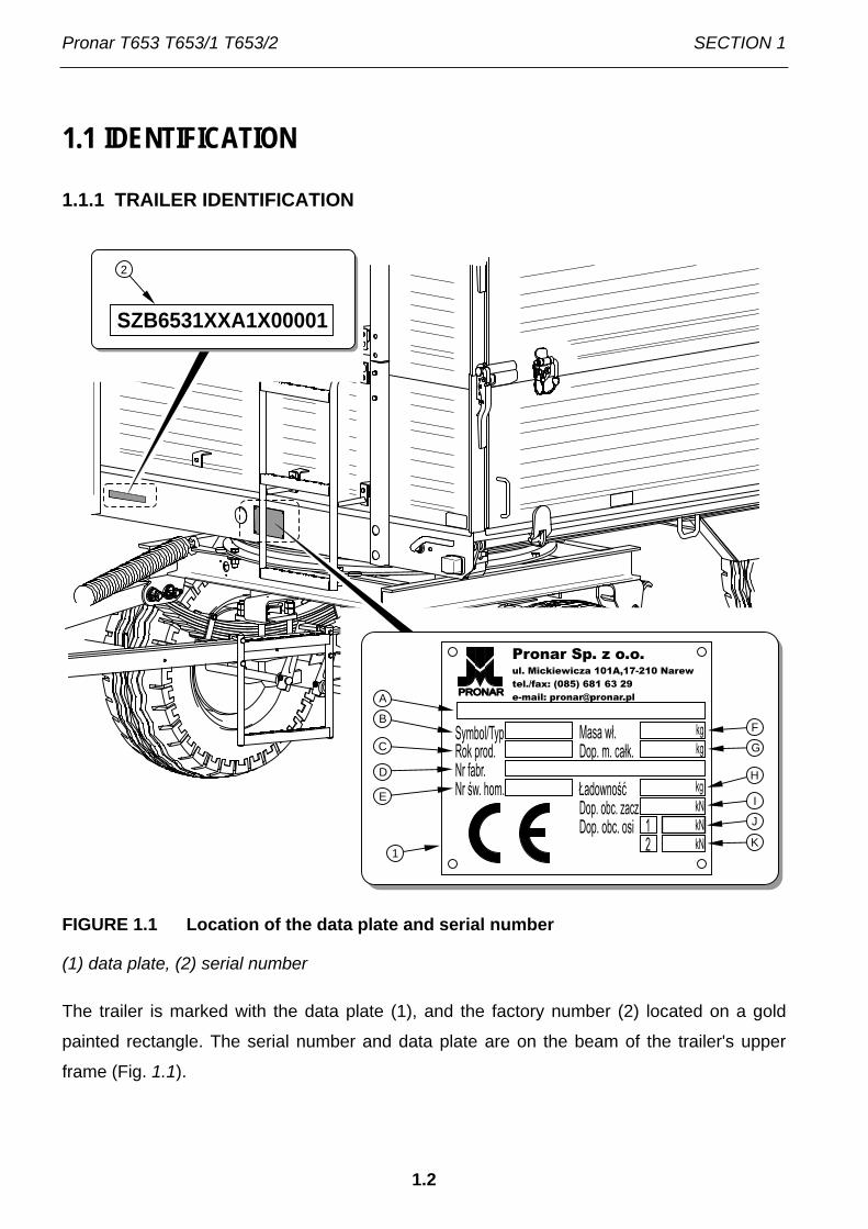
1.1 IDENTIFICATION
1.1.1 TRAILER IDENTIFICATION
FIGURE 1.1 Location of the data plate and serial number
(1) data plate, (2) serial number
The trailer is marked with the data plate (1), and the factory number (2) located on a gold
painted rectangle. The serial number and data plate are on the beam of the trailer's upper
frame (Fig. 1.1).
SZB6531XXA1X00001
2
1
PRONARA
B
C
D
F
G
H
I
K
J
E

SECTION 1 Pronar T653 T653/1 T653/2
1.3
When buying the trailer check that the serial numbers on the machine agree with the number
written in the WARRANTY BOOK, in the sales documents and in the OPERATOR'S
MANUAL. The meaning of the individual fields found on the data plate are presented in the
table below:
TABLE 1.1 Markings on data plate
ITEM MARKING
A General description and purpose
B Symbol /Type
C Year of manufacture
D Seventeen digit serial number (VIN)
E Official certificate number
F Tare weight
G Maximum gross weight
H Carrying capacity
I Maximum hitch load (not applicable)
J Permissible front axle load
K Permissible rear axle load
1.1.2 AXLE IDENTIFICATION
The factory number of the axle shaft and its type are stamped onto the data plate (2) secured
to the axle shaft beam (1) – figure (1.2).

Pronar T653 T653/1 T653/2 SECTION 1
1.4
FIGURE 1.2 Location of the axle data plate
(1) wheel axle, (2) data plate
1.1.3 LIST OF FACTORY NUMBERS
TIP
In the event of ordering a replacement part or in the case of the appearance of problems it is often essential to give the factory numbers of parts or the VIN number of the trailer, therefore it is recommended that these numbers are inscribed in the spaces below.
VIN number
S Z B 6 5 3 0 0 X
FRONT AXLE FACTORY NUMBER AND TYPE
REAR AXLE FACTORY NUMBER AND TYPE
1.2 PROPER USE
The trailer is designed for transport of harvested crops and agricultural products as well as
loose, bulk and long load materials at the farm and on public roads. It is acceptable to
12

SECTION 1 Pronar T653 T653/1 T653/2
1.5
transport construction materials, mineral fertilisers and other loads, if fulfilling conditions
indicated in section 4. Non-compliance with the recommendations of the carriage and loading
of goods described by the Manufacturer and the road transport regulations in force in the
country in which the trailer is used, shall void the guarantee and is regarded as use of the
machine not according to its intended purpose.
The trailer is not intended or designed for transporting people, animals or goods classified as
dangerous materials.
IMPORTANT!
The trailer must not be used for purposes other than those for which it is intended. The user MUST NOT:
• transport people, animals, hazardous materials, chemically aggressive loads that will corrode the construction elements of the trailer (causing corrosion of steel, destruction of paint coat, dissolving plastic elements and destruction of rubber elements etc.),
• transport incorrectly secured load, which during travel may cause contamination of the road and natural environment,
• transport incorrectly secured load, which during travel may change position in load box or fall out of the load box,
• transport loads, whose centre of gravity may destabilise the trailer,
• transport loads, which have uneven load distribution and/or overload axles and suspension elements.
The trailer is constructed according to current safety requirements and engineering
standards. The brake system and the light and indicator system meet the requirements of
road traffic regulations. The maximum speed of the trailer on public roads is 30 km/h in
Poland (pursuant to Road Traffic Act of June 20th 1997, art. 20). In the countries where the
trailer is used, the limits stipulated by the road traffic legislation in force in a given country
must be observed. The trailer's speed must not, however, be greater than the maximum
design speed of 30 km/h.
Using it as intended also involves all actions connected with the safe and proper operation
and maintenance of the machine. In connection with this the user is obliged to:
Pronar T653 T653/1 T653/2 SECTION 1
1.6
• carefully read the OPERATOR'S MANUAL of the trailer and the WARRANTY
BOOK and conform with the recommendations contained in these documents,
• understand the trailer's operating principle and how to operate it safely and
correctly,
• adhere to the established maintenance and adjustment plans,
• comply with general safety regulations while working,
• prevent accidents,
• comply with the road traffic regulations and transport regulations in force in a
given country, in which the trailer is used,
• carefully read the Operator's Manual and comply with its recommendations,
• only hitch the trailer to an agricultural tractor, which fulfils all the requirements
made by the trailer's Manufacturer.
The trailer may only be used by persons, who:
• are familiar with the contents of this publication and with the contents of the
agricultural tractor Operator's Manual,
• have been trained in trailer operation and safe operation,
• have the required authorisation to drive and are familiar with the road traffic
regulations and transport regulations.
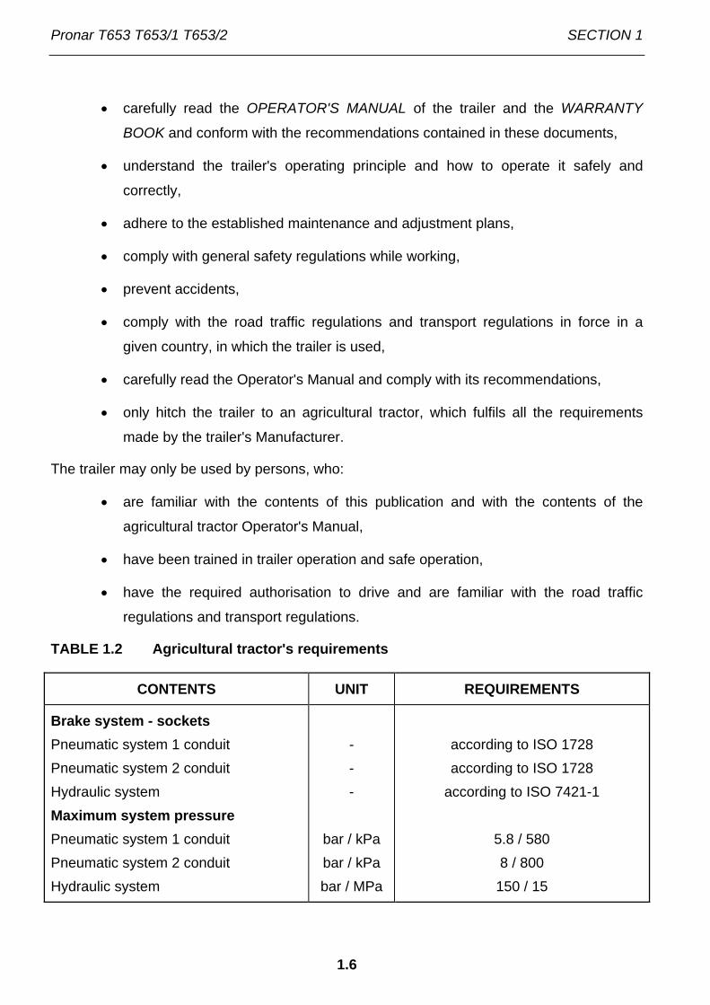
TABLE 1.2 Agricultural tractor's requirements
CONTENTS UNIT REQUIREMENTS
Brake system - sockets Pneumatic system 1 conduit Pneumatic system 2 conduit Hydraulic system Maximum system pressure Pneumatic system 1 conduit Pneumatic system 2 conduit Hydraulic system
- - -
bar / kPa bar / kPa bar / MPa
according to ISO 1728 according to ISO 1728
according to ISO 7421-1
5.8 / 580 8 / 800
150 / 15

SECTION 1 Pronar T653 T653/1 T653/2
1.7
CONTENTS UNIT REQUIREMENTS
Hydraulic tipper system Hydraulic oil Maximum system pressure Oil demand:
- bar / MPa
l
L HL 32 Lotos (1)
160 / 16 8
Electrical system Electrical system voltage Attachment socket
V -
12
7 polar compliant with ISO 1724
Required tractor hitch Type
-
Upper transport hitch
Other requirements Min. tractor power T653 T653/1 T653/2
kW / HP kW / HP kW / HP
26.7 / 36.3 30.6 / 41.6 34.4 / 46.7
(1) – use of other oil is permitted, on condition that it may be mixed with the oil in the trailer. Detailed
information may be found on the product information card.
In the event that the trailer shall be hitched to a second trailer it must fulfil the requirements
stipulated in table (1.3).
TABLE 1.3 Requirements for second trailer
CONTENTS UNIT REQUIREMENTS
Maximum gross weight T653 T653/1 T653/2 (1)
kg kg kg
6,000 7,100 8,120
Pronar T653 T653/1 T653/2 SECTION 1
1.8
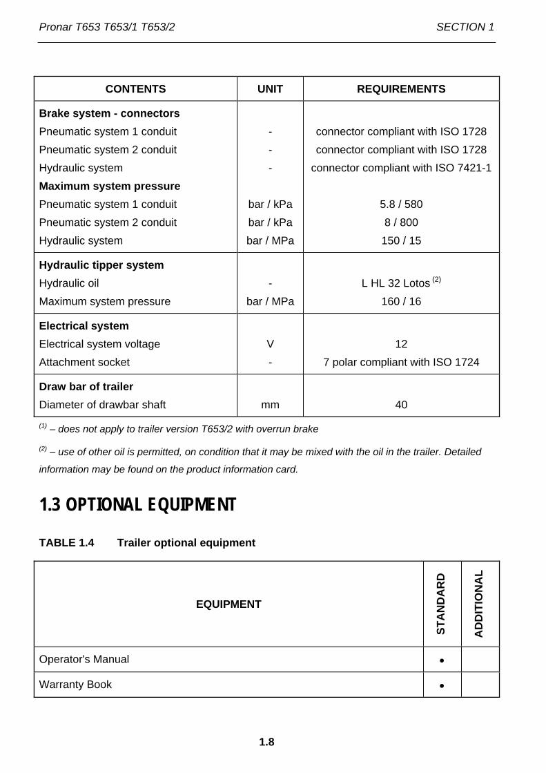
CONTENTS UNIT REQUIREMENTS
Brake system - connectors Pneumatic system 1 conduit Pneumatic system 2 conduit Hydraulic system Maximum system pressure Pneumatic system 1 conduit Pneumatic system 2 conduit Hydraulic system
- - -
bar / kPa bar / kPa bar / MPa
connector compliant with ISO 1728 connector compliant with ISO 1728
connector compliant with ISO 7421-1
5.8 / 580 8 / 800
150 / 15
Hydraulic tipper system Hydraulic oil Maximum system pressure
- bar / MPa
L HL 32 Lotos (2)
160 / 16
Electrical system Electrical system voltage Attachment socket
V -
12
7 polar compliant with ISO 1724
Draw bar of trailer Diameter of drawbar shaft
mm
40
(1) – does not apply to trailer version T653/2 with overrun brake
(2) – use of other oil is permitted, on condition that it may be mixed with the oil in the trailer. Detailed
information may be found on the product information card.
1.3 OPTIONAL EQUIPMENT
TABLE 1.4 Trailer optional equipment
EQUIPMENT
STA
ND
AR
D
AD
DIT
ION
AL
Operator's Manual •
Warranty Book •

SECTION 1 Pronar T653 T653/1 T653/2
1.9
EQUIPMENT
STA
ND
AR
D
AD
DIT
ION
AL
Pneumatic system 1 conduit (1) •
Overrun brake (2) •
Rear hitch, •
Slow-moving vehicle warning sign •
Warning reflective triangle •
Frame with tarpaulin cover •
Wall extension set, lower ladder, drawbar ladder (3) •
Hand brake (1) •
Wheel wedges •
Drawbar with hitching eye ∅40 mm •
Clamping cable with cable extraction mechanism •
Chute •
Spare wheel holder with spare wheel •
(1) – does not apply to trailer version T653/2 with overrun brake
(2) – applies to trailer version T653/2 with overrun brake
(3) – does not apply to trailer version T653
Some standard equipment elements, which were listed in table (1.4), may not be present in
the delivered trailer. This allows the possibility of ordering new machines with a different set
of optional equipment, replacing standard equipment.
Information concerning tyres is placed at the end of this publication in ANNEX A.

Pronar T653 T653/1 T653/2 SECTION 1
1.10
1.4 WARRANTY TERMS
PRONAR Sp. z o.o., Narew guarantees the reliable operation of the machine when it is used
according to its intended purpose as described in the OPERATOR'S MANUAL.
The repair period is specified in the WARRANTY BOOK.
The guarantee does not apply to those parts and sub-assemblies of the machine, which are
subject to wear in normal usage conditions, regardless of the warranty period. Consumables
include the following parts/sub-assemblies:
• drawbar hitching eye,
• pneumatic system connector filters,
• tyres,
• brake shoes,
• bulbs and LED lamps,
• seals,
• bearings.
The warranty service only applies to such cases as: mechanical damage, which is not the
user's fault, factory defects of parts, etc.
In the event of damage arising from:
• mechanical damage which is the user's fault, caused by road accidents,
• by inappropriate use, adjustment or maintenance, use of the trailer for purposes
other than those for which it is intended,
• use of damaged machine,
• repairs carried out by unauthorised persons, improperly carried out repairs,
• making unauthorised alterations to machine design,
the user will lose the right to warranty service.

SECTION 1 Pronar T653 T653/1 T653/2
1.11
TIP
Demand that the seller carefully and precisely fills out the Warranty Book and guarantee repair coupons. A missing date of purchase or sale point stamp, may make the user ineligible for any warranty repair or refund.
The user is obliged to report immediately on noticing any wear in the paint coating or traces
of corrosion, and to have the faults rectified whether they are covered by the guarantee or
not. Detailed guarantee regulations are contained in the WARRANTY BOOK attached to
each machine.
Modification of the trailer without the written consent of the Manufacturer is forbidden. In
particular, do NOT weld, drill holes in, cut or keep the main structural elements of the
machine, which have a direct impact on the machine operation safety.
1.5 TRANSPORT
The trailer is ready for sale completely assembled and does not require packing. Packing is
only required for the machine's technical documentation and any extra fittings. The trailer is
delivered to the user either transported on a vehicle or, after being attached to a tractor,
independently (towed).
1.5.1 TRANSPORT ON VEHICLE.
Loading and unloading of trailer from vehicle shall be conducted using loading ramp with the
aid of an agricultural tractor. During work adhere to the general principles of Health and
Safety at Work applicable to reloading work. Persons operating reloading equipment must
have the qualifications required to operate these machines. The trailer must be properly
connected with the tractor according to the requirements closed in this Operators Manual.
The trailer brake system must be started in checked before driving off or onto ramp.
The trailer should be attached firmly to the platform of the vehicle using straps or chains fitted
with a tightening mechanism. Securing elements should be attached to the transport catches
designed for this purpose (1) – figure (1.3), permanent structural elements of the trailer
(longitudinal and transverse frame sections etc.). Transport catches (hooks and eyes) are
welded to upper longitudinal frame (2), with one pair on each side of the trailer. Use certified
and technically reliable securing measures. Worn straps, cracked securing catches, bent or

Pronar T653 T653/1 T653/2 SECTION 1
1.12
corroded as well as other damage may disqualify use of the given element from use.
Carefully read the information contained in the Operator's Manual of the given securing
measure. Wedges, wooden blocks or other objects without sharp edges should be placed
under the wheels of the trailer to prevent it from rolling. Trailer wheel locks must be nailed to
the low platform planks of the vehicle or secured in another manner preventing their
movement. The number of securing elements (cables, straps, chains and stay etc.) and the
force necessary for their tensioning depends on a number of things, including weight of the
trailer, the construction of vehicle carrying trailer, speed of travel and other conditions. For
this reason it is impossible to define the securing plan precisely. A correctly secured trailer
does not change its position with regard to the transport in vehicle. The securing elements
must be selected according to the guidelines of the Manufacturer of these elements. In case
of doubt apply a greater number of securing straps in order to immobilise the trailer. If
necessary, sharp edges of trailer should be protected at the same time protecting the
securing straps from breaking during transport.
IMPORTANT!
When being road transported on a motor vehicle the trailer must be mounted on the vehicle's platform in accordance with the transport safety requirements and the regulations. Driver of the vehicle should be particularly careful during travel. This is due to the vehicle's centre of gravity shifting upwards when loaded with the machine. Use only certified and technically reliable securing measures. Carefully read the manufacturer's instructions for the securing measures.
During reloading work, particular care should be taken not to damage parts of the machine's
fittings or the lacquer coating. The tare weight of the trailer in condition ready for travel is
given in table (3.1).
DANGER
Incorrect application of securing measures may cause an accident.

SECTION 1 Pronar T653 T653/1 T653/2
1.13
FIGURE 1.3 Positioning of transport lugs
(1) transport lug, (2) upper longitudinal frame, (3) lower longitudinal frame
1.5.2 INDEPENDENT TRANSPORT BY THE USER.
In the event of independent transport by the user after purchase of the trailer, the user must
read the trailer Operator's Manual and adhere to the recommendations contained therein.
Independent transport involves towing the trailer with own agricultural tractor to destination.
During transport adjust travel speed to the prevailing road conditions, but do not exceed the
maximum design speed.
IMPORTANT!
When transporting independently, the user must carefully read this operator's manual and observe its recommendations.
123

Pronar T653 T653/1 T653/2 SECTION 1
1.14
1.6 ENVIRONMENTAL HAZARDS
A hydraulic oil leak constitutes a direct threat to the natural environment owing to its limited
biodegradability. Because of the low solubility of oil in water, it is not highly toxic to living
organisms. An oil leak into water reservoirs may however lead to a reduction of the oxygen
content. While carrying out maintenance and repair work which involves the risk of an oil
leak, this work should take place on an oil resistant floor or surface. In the event of oil leaking
into the environment, first of all contain the source of the leak, and then collect the leaked oil
using available means. Remaining oil should be collected using sorbents, or by mixing the oil
with sand, sawdust or other absorbent materials. The oil pollution, once gathered up, should
be kept in a sealed, marked, hydrocarbon resistant container. The container should be kept
away from heat sources, flammable materials and food.
DANGER
Used hydraulic oil or gathered remains mixed with absorbent material should be stored in a precisely marked container. Do not use food packaging for this purpose.
Oil which has been used up or is unsuitable for further use owing to a loss of its properties
should be stored in its original packaging in the conditions described above. Waste oil should
be taken to the appropriate facility dealing with the re-use of this type of waste. Waste code:
13 01 10. Detailed information concerning hydraulic oil may be found on the product's
Material Safety Data Sheet.
TIP
The hydraulic system of the trailer is filled with L-HL32 Lotos hydraulic oil.
IMPORTANT!
Waste oil should only be taken to the appropriate facility dealing with the re-use of this type of waste. Do NOT throw or pour oil into sewerage or water tanks.
SECTION 1 Pronar T653 T653/1 T653/2
1.15
1.7 WITHDRAWAL FROM USE
In the event of decision by the user to withdraw the trailer from use, comply with the
regulations in force in the given country concerning withdrawal from use and recycling of
machines withdrawn from use. Before commencing dismantling, totally remove the oil from
the hydraulic system and reduce air pressure completely in the pneumatic brake system (e.g.
using air tank drain valve).
DANGER
During dismantling personal protection equipment shall be used i.e. protective clothing, boots, gloves and protective goggles etc. Avoid contact of skin with oil. Do not allow used hydraulic oil to spill.
When spare parts are changed, worn out or damaged parts that cannot be reclaimed should
be taken to a collection point for recyclable raw materials. Hydraulic oil should be taken to the
appropriate facility dealing with the re-use of this type of waste.

Pronar T653 T653/1 T653/2 SECTION 1
1.16

SECTION
2
SAFETY IN USE

Pronar T653 T653/1 T653/2 SECTION 2
2.2
2.1 BASIC SAFETY RULES
2.1.1 USE OF TRAILER
• Before using the trailer, the user must carefully read this Operator's Manual and
the WARRANTY BOOK. When operating the machine, the operator must comply
with the recommendations.
• The trailer may only be used and operated by persons qualified to drive
agricultural tractors and agricultural machines and trained in the use of the
machine.
• If the information contained in the Operator's Manual is difficult to understand,
contact a seller, who runs an authorised technical service on behalf of the
manufacturer, or contact the manufacturer directly.
• Careless and improper use and operation of the trailer, and non-compliance with
the recommendations given in this operator's manual is dangerous to your health.
• Be aware of existence of a minimal risk, and for this reason the fundamental basis
for using this trailer should be the application of safety rules and sensible
behaviour.
• The machine must never be used by persons, who are not authorised to drive
agricultural tractors, including children and people under the influence of alcohol
or other drugs.
• Non-compliance with the safety rules of this Operator’s Manual can be dangerous
to the health and life of the operator and others.
• The trailer must not be used for purposes other than those for which it is intended.
Anyone who uses the trailer other than the way intended takes full responsibility
for himself for any consequences of this potentially improper use. Use of the
machine for purposes other than those for which it is intended by the
Manufacturer may invalidate the guarantee.
• Assembly and disassembly of extension walls, the frame and tarpaulin cover, can
only be carried out with the use of appropriate platforms, ladders or from a ramp.
These fittings must be in good condition to fully protect the persons working on

SECTION 2 Pronar T653 T653/1 T653/2
2.3
them against falling. The above procedure should be performed by at least two
persons.
• In the final phase of folding the tarpaulin cover, at all times hold with one hand the
top of the front frame or other permanent structural element. Non-compliance with
this rule can put the user at risk of falling.
2.1.2 HITCHING AND DISCONNECTING FROM TRACTOR
• Do NOT hitch trailer to tractor, if it does not fulfil the requirements made by the
Manufacturer (minimal tractor power requirement, lack of required tractor hitch
etc.) – compare table (1.2) AGRICULTURAL TRACTOR REQUIREMENTS.
Before hitching trailer make certain that oil in external hydraulic system of tractor
may be mixed with the hydraulic oil of the trailer.
• Before hitching trailer to tractor check that tractor and trailer are in good technical
condition.
• During hitching only use the upper transport hitch of the tractor. After completing
the coupling of the machine check the safety of the hitch. Carefully read the
tractor Operator's Manual. If the tractor is equipped with an automatic hitch, make
certain that the coupling operation is completed.
• Be especially careful when attaching the machine.
• When attaching, there must be nobody between the trailer and the tractor.
• Do NOT proceed with disconnecting trailer from the tractor when load box is
raised.
• Coupling and uncoupling the trailer may only take place when the machine is
immobilised by use of the parking brake.
2.1.3 COUPLING AND UNCOUPLING SECOND TRAILER
• Do NOT connect a second trailer, if it does not fulfil the requirements made by the
Manufacturer of (lack of required drawbar eye, exceeding permissible total weight
etc.) – compare table (1.2) REQUIREMENTS FOR SECOND TRAILER. Before
connecting machines make certain that the oil in both trailers may be mixed.

Pronar T653 T653/1 T653/2 SECTION 2
2.4
• Only machines built on a double axle chassis with permissible total weight
described in table (1.3) may be hitched to the trailer. Permissible total weight of
linked vehicle is dependent upon the trailer version.
• Before hitching trailer to tractor check that both machines are in good technical
condition.
• After completing the coupling of the machine check the safety of the hitch.
• Be especially careful when attaching the machine.
• When attaching, there must be nobody between the trailers. Person assisting
hitching up machines should stand outside the area of danger and be visible to
the tractor driver at all times.
• Do NOT proceed with disconnecting the second trailer from the tractor when load
box is raised.
2.1.4 HYDRAULIC AND PNEUMATIC SYSTEMS
• When operating, the hydraulic and pneumatic systems are under high pressure.
• Regularly check the technical condition of the connections and the hydraulic and
pneumatic leads. There must no oil or air leaks.
• Cut-off valve in the hydraulic tipping system limits the tipping angle of the load
box when tipped to the sides and to the rear. The length of the control cable
controlling this valve is factory adjusted by the Manufacturer and must not be
changed when the trailer is used.
• In the event of malfunction of the hydraulic or pneumatic system, do not use the
trailer until the malfunction is corrected.
• When connecting the hydraulic conduits to the tractor, make sure that the tractor's
hydraulic system and trailer are not under pressure. If necessary reduce residual
pressure in the system.
• In the event of injuries being caused by pressurised hydraulic oil, contact a doctor
immediately. Hydraulic oil may find its way under the skin and cause infections. In
the event of contact of oil with eye, rinse with large quantity of water and in the
event of the occurrence of irritation consultant a doctor. In the event of contact of

SECTION 2 Pronar T653 T653/1 T653/2
2.5
oil with skin wash the area of contact with water and soap. Do not apply organic
solvents (petrol, kerosene).
• Use the hydraulic oil recommended by the manufacturer.
• After changing the hydraulic oil, the used oil should be properly disposed of. Used
oil or oil, which has lost its properties, should be stored in original containers or
replacement containers resistant to action of hydrocarbons. Replacement
containers must be clearly marked and appropriately stored.
• Do not store hydraulic oil in packaging designed for storing food or foodstuffs.
• Rubber hydraulic conduits must be replaced every 4 years regardless of their
technical condition.
2.1.5 LOADING AND UNLOADING
• Before raising load box the tipping pins should be placed on the intended
unloading side. Check if the pins are correctly inserted.
• Unloading and loading of trailer may only take place when the machine is
positioned on level and hard surface and connected to tractor. Tractor and trailer
must be placed to drive forwards.
• Use only original tipping pins with a handle. Using third-party pins could damage
the trailer.
• Loading and unloading work should be carried out by someone experienced in
this type of work.
• Before loading make certain that linking cables are laid and release mechanism is
set in proper position and secured with the aid of linchpin. If the loaded material
does not exert any pressure on the trailer sides it is permitted to dismantle
clamping cable. If pressure is exerted it may cause damage to trailer sides.
• The load must be arranged in such a way that it does not threaten the stability of
the trailer, and does not hinder driving.
• Trailer with net extensions may only be unloaded by tipping load box to the rear.
• Do NOT drive with the load box raised.

Pronar T653 T653/1 T653/2 SECTION 2
2.6
• Ensure that during unloading / loading raising the load box nobody is near the
trailer. Before tipping load box ensure that there is visibility and make certain that
there are no bystanders.
• The trailer is not intended for transporting people, animals or hazardous
materials.
• Keep a safe distance from overhead electric power lines during unloading and
when load box is raised.
• The arrangement of the load may not cause an overload on the axle of the trailer.
• When opening load box side wall locks take particular care, because of the
pressure of the load on the wall.
• Do NOT tip of the load box in windy conditions.
• When closing or opening the rear grain chute gate or the walls and extensions
take particular care to avoid crushing fingers.
• Bulk materials loaded in excess of 1 m can be unloaded by tipping the load box to
the rear only.
• Incorrect load distribution and overloading the machine may cause the trailer to
tip over or cause damage to its components.
• Do NOT go or place hand between open side and load box.
• If the load does not pour from the raised load box immediately cease unloading.
The trailer may only be tipped again after removing the object, which prevented
the load from pouring.
• During winter particular attention must be paid to loads, which may freeze during
transport. When tipping the load box with frozen load the trailer may become
unstable and tip over.
• Do NOT raise the load box if there is any danger whatsoever that the box will tip
over.
• Do NOT jerk the trailer forwards if bulky or reluctant to pour load it is not
unloaded.
• Do NOT climb on load box during loading and unloading.
SECTION 2 Pronar T653 T653/1 T653/2
2.7
• Do NOT tip the loaded load box when the sides are closed.
• Lower the load box before proceeding to deal with a malfunction. If it is necessary
to raise the load box then secure it against dropping with the aid of supports. The
load box may not be loaded, and the trailer must be connected to a tractor and
secured with the aid of wedges and also immobilised with the parking brake.
• After completing unloading, ensure that the load box is empty.
2.1.6 TRANSPORTING THE MACHINE
• During travel on public roads comply with the road traffic regulations and transport
regulations in force in a given country, in which the trailer is used.
• Do not exceed the permitted speed arising from limitations of road conditions and
construction limitations. Adjust travel speed to the prevailing road conditions,
trailer load and road traffic regulations limits.
• The machine must NOT be left unsecured. When not connected to the tractor, the
trailer must be immobilised with parking brake and protected against rolling with
wedges or other objects without sharp edges placed under the front and back
wheels.
• Before driving off make certain that the trailer is correctly hitched to the tractor.
• Do NOT move off or drive when load box is raised.
• Prior to moving off make sure that tipping pins connecting the loadbox and the
lower frame and the side wall hinge pins are secured against falling out. Check if
rear side pouring chute is secure. Check that all sides and extensions are
properly closed. Check correctness of the securing of linking cables and a
security of cable release mechanism.
• Before using the trailer always check its technical condition, especially in terms of
safety. In particular, check the technical condition of the hitch system, the axle
system, the brake system, indicator lights and the connective elements of the
hydraulic, pneumatic and electrical systems.
• Wedges (1), should be placed only under one wheel (one in front of the wheel,
the second behind the wheel - figure (2.1)). Wedges should not be placed under
wheels of the front axle.

Pronar T653 T653/1 T653/2 SECTION 2
2.8
FIGURE 2.1 Method of placing wedges
(1) securing wedge, (2) wheel of rear axle
• Before driving off check that the parking brake is released, the braking force
regulator is positioned in the proper position (applies to pneumatic systems with a
manual three position regulator).
• The trailer is designed to operate on slopes up to 8° . Driving trailer across ground
with steeper slopes may cause the trailer to tip over as a result of loss of stability.
• While driving on public roads the trailer must be fitted with a certified or
authorised reflective warning triangle.
• Periodically drain water from the air tank in pneumatic system. During frosts,
freezing water may cause damage to pneumatic system components.
• Reckless driving and excessive speed may cause accidents.
1
1
2

SECTION 2 Pronar T653 T653/1 T653/2
2.9
• A load protruding beyond the edge of the trailer should be indicated according to
the road traffic regulations. Do NOT transport loads forbidden by the
Manufacturer.
FIGURE 2.2 Mounting place for slow-moving vehicle sign
(1) warning sign, (2) attachment point
• If the trailer is the last vehicle in the group, a slow-moving vehicle sign should be
placed on the trailer's rear load box wall – (figure 2.2). The warning sign (1)
1
2

Pronar T653 T653/1 T653/2 SECTION 2
2.10
should be attached using the specifically prepared holder (2), riveted to the rear
wall of the load box.
• The trailer's maximum carrying capacity must not be exceeded. Exceeding the
carrying capacity may lead to damage to the machine, loss of stability while
driving, scattering of the load and danger while driving. The brake system is
adjusted to the gross weight of the trailer, exceeding the weight limit causes
drastic reduction of basic braking effectiveness.
• Load must be uniformly distributed and it must not obstruct visibility or hinder
driving. The load must be secured so that it cannot move or fall over.
• During reversing one should use the assistance of another person. During
manoeuvring the person helping must stay at a safe distance from the danger
zone and be visible all the time to the tractor driver.
• Do NOT attempt to board trailer while travelling.
• Do NOT park trailer on slope.
2.1.7 TYRES
• When working with tyres, the trailer should be immobilised with parking brake and
secured against rolling by placing wedges under wheel. The wheel can be taken
off only when the trailer is not loaded.
• Repair work on the wheels or tyres should be carried out by persons trained and
entitled to do so. This work should be carried out using appropriate tools.
• Inspection of nut tightening should be carried out after first use of trailer, after first
travel with loading and then after 6 months use. In the event of intensive work
checking the nut tightening should at least every 100 kilometres. The inspection
should be repeated individually if a wheel has been removed from the wheel axle.
• Avoid potholes, sudden manoeuvres or high speeds when turning.
• Check the tyre pressure regularly. Pressure and tyres should be also checked
after the whole day of intensive work. Please note that higher temperatures could
raise tyre pressure by as much as 1 bar. At high temperatures and pressure,
reduce load or speed. Do not release air from warm tyres to adjust the pressure
or the tyres will be underinflated when temperatures return to normal.

SECTION 2 Pronar T653 T653/1 T653/2
2.11
• Protect valves using suitable caps to avoid soiling.
2.1.8 MAINTENANCE
• During the warranty period, any repairs may only be carried out by Warranty
Service authorised by the manufacturer. After the expiry of the warranty period it
is recommended that possible repairs to the trailer be performed by specialised
workshops.
• In the event of any fault or damage whatsoever, do not use the trailer until the
fault has been fixed.
• During work use the proper, close-fitting protective clothing, gloves, protective
goggles and appropriate tools.
• Any modification to the trailer frees the manufacturer from any responsibility for
damage or detriment to health, which may arise as a result.
• The trailer can only be stood on when it is absolutely motionless and the tractor
engine is switched off. Tractor and trailer should be secured using parking brake
and in addition wedges should be placed beneath trailer wheel. Ensure that
unauthorised persons do not have access to the tractor's cab.
• Regularly check the condition of nut and bolt connections, in particular
connections of drawbar eye with drawbar and wheel nuts.
• Regularly service machine according to schedule defined by Manufacturer.
• Before beginning work requiring raising of load box, it must be emptied and
secured by supports to prevent accidental falling. The trailer must at this time be
hitched to the tractor and secured with wedges and parking brake.
• Before beginning repair works on hydraulic or pneumatic systems reduce oil or air
pressure completely.
• Servicing and repair work should be carried out in line with the general principles
of workplace health and safety. In the event of injury, the wound must be
immediately cleaned and disinfected. In the event of more serious injuries, seek a
doctor's advice.

Pronar T653 T653/1 T653/2 SECTION 2
2.12
• Repair, maintenance and cleaning work should be carried out with the tractor's
engine switched off and the ignition key removed. Tractor and trailer should be
secured using parking brake and in addition wedges should be placed beneath
trailer wheel. Ensure that unauthorised persons do not have access to the
tractor's cab.
• During maintenance or repair work trailer may be unhitched from tractor, but
secured with wedges and parking brake. During this work the load box may not
be raised.
• Should it be necessary to change individual parts, use only those parts indicated
by the Manufacturer. Non-adherence to these requirements may put the user and
other people's health and life at risk, and also damage the machine and invalidate
the guarantee.
• Before welding or electrical work, the trailer should be disconnected from the
power supply. The paint coating should be cleaned. Burning paint fumes are
poisonous for people and animals. Welding work should be carried out in a well lit
and well ventilated space.
• During welding work pay attention to flammable or fusible elements (parts of the
pneumatic, electric and hydraulic systems, plastic parts). If there is a risk that they
will catch fire or be damaged, they should be removed or covered with non-
flammable material before commencing welding work. Before beginning work
prepare a CO2 or foam extinguisher.
• In the event of work requiring the trailer to be raised, use properly certified
hydraulic or mechanical lifts for this purpose. After lifting the machine, stable and
durable supports must also be used. Work must not be carried out under a trailer,
which has only been raised with a lift or jack.
• The trailer must not be supported using fragile elements (bricks or concrete
blocks).
• After completing work associated with lubrication, remove excess oil or grease.
The trailer should be kept clean and tidy.
• Exercise caution when climbing on top of the load box. Climbing on top of the
load box is possible by use of ladders placed on the front wall, extension and

SECTION 2 Pronar T653 T653/1 T653/2
2.13
draw bar and also folding steps inside the load box. Components not intended to
aid access may not be used for this purpose. Before entering load box prevent
trailer moving with parking brake and wedges.
• Do NOT make independent repairs of control valve, brake cylinders, tipping
cylinder ram and braking force regulator. In the event of damage to these
elements, repair should be entrusted to authorised service point or replace
elements with new parts.
• Do NOT make repairs to drawbar (straightening, repairing or welding). A
damaged drawbar must be replaced.
• Do NOT install additional appliances or fittings not according to the specifications
defined by the Manufacturer.
• The trailer may only be towed when axles and wheels, lighting system and brakes
are reliable.
2.2 DESCRIPTION OF MINIMAL RISK
Pronar Sp. z o. o. in Narew has made every effort to eliminate the risk of accidents. There is,
however, a certain minimal risk, which could lead to an accident, and this is connected mainly
with the actions described below:
• using the trailer for purposes other than those for which it is intended,
• being between the tractor and the trailer while the engine is running and when the
machine is being attached or hitched to second trailer
• being on the machine during work,
• not keeping a safe distance during loading or unloading of trailer,
• operation of the trailer by persons under the influence of alcohol,
• making modifications to the machine without the consent of the Manufacturer,
• cleaning, maintenance and technical checks of the trailer.
• presence of persons or animals in areas invisible from the driver's position.
The minimal risk may be kept to a minimum by following the recommendations below:
Pronar T653 T653/1 T653/2 SECTION 2
2.14
• prudent and unhurried operation of the machine,
• sensible application of the remarks and recommendations contained in the
Operator's Manual,
• keeping a safe distance from forbidden or dangerous places during unloading,
loading and hitching trailer,
• carrying out repair and maintenance work in line with operating safety rules,
• carrying out repair and maintenance work by persons trained to do so,
• using strictly suited protective clothing, and appropriate tools,
• ensuring unauthorised persons have no access to the machine, especially
children.
• keeping a safe distance from forbidden or dangerous places
• a ban on being on the machine during travel, loading or unloading.
2.3 INFORMATION AND WARNING DECALS
The trailer is labelled with the information and warning decals mentioned in table (2.1). The
symbols are positioned as presented in figure (2.3). Throughout the time it is in use, the user
of the machine is obliged to take care that notices and warning and information symbols
located on the trailer are clear and legible. In the event of their destruction, they must be
replaced with new ones. Safety decals are available from your PRONAR dealer or directly
from PRONAR customer service. New assemblies, changed during repair, must be labelled
once again with the appropriate safety signs. During trailer cleaning do not use solvents
which may damage the coating of information label stickers and do not subject them to strong
water jets.

SECTION 2 Pronar T653 T653/1 T653/2
2.15
TABLE 2.1 Information and warning decals
ITEM DECAL MEANING OF SYMBOL
1
Trailer version.
2
Note. Before starting work, carefully read the Operator's Manual.
3
Before beginning servicing or repairs, switch off tractor's
engine and remove key from ignition Ensure that
unauthorised persons do not have access to the tractor's
cab.
4
Before climbing onto the trailer, switch off tractor's
engine and remove key from ignition.

Pronar T653 T653/1 T653/2 SECTION 2
2.16
ITEM DECAL MEANING OF SYMBOL
5
Caution! Danger of electric shock.
Keep a safe distance from overhead electric power lines
during unloading.
6
Danger of crushing Do NOT perform any
maintenance or repairs on the load box that is loaded,
raised or not supported.
7
Regularly check if the nuts and bolts fixing the wheels and other components are
properly tightened.
8
Grease the trailer according to the recommendations in
the Operator's Manual
9
Conduit supplying hydraulic brake system.
10
Conduit supplying hydraulic tipping system.

SECTION 2 Pronar T653 T653/1 T653/2
2.17
ITEM DECAL MEANING OF SYMBOL
11
Trailer carrying capacity (depends on vehicle version).
12
Positions of control valve controlling work of hydraulic
tipping system (1 or 2 trailers).
13
Trailer coupling information - exclusively with upper
transport hitch.
14
Air pressure in the tyres. (1)
(1) – pressure value should be adapted to tyres
Numbers in the item column correspond to labels in figure (2.3)
Decals – items (9) and (10) are placed on hydraulic conduits. Decal (12) is placed near the
hydraulic valve.

Pronar T653 T653/1 T653/2 SECTION 2
2.18
FIGURE 2.3 Locations of information and warning decals.
1
2
3
13
144
7
8
5 6 11

SECTION
3
DESIGN AND OPERATION

Pronar T653 T653/1 T653/2 SECTION 3
3.2
3.1 TECHNICAL SPECIFICATION
TABLE 3.1 Basic technical specification
CONTENTS UNIT T653 T653/1 T653/2
Trailer dimensions Total length Total width Total height Internal load box dimensions Length Width (front) Width (rear) Height
mm mm mm
mm mm mm mm
6 140 2 230 1 585
4 010 2 010 2 060 500
6 140 2 230
1 630(2 130)
4 010 2 010 2 060
500(1 000)
6 140 2 230
1 630(2 130)
4 010 2 010 2 060
500(1,000)
Weight and carrying capacity Tare weight Maximum gross weight Maximum carrying capacity
kg kg kg
1 950 5,950 4 000
1 925(2 105)
7 105 5 180(5 000)
1 940(2 120)
8,120 6 180(6 000)
Other information Axle track Axle base Load volume Load surface Lift of load surface Load box tipping angle - to the sides - to the rear Electrical system voltage Maximum speed Noise emission level
mm mm m3
m2
mm
(°) (°) V
km/h dB
1,600 2,700 4.1 8.2
1 050
46 42 12 30
below 70
1,600 2,700
4.1(8.2) 8.2
1 095
46 42 12 30
below 70
1,600 2,700
4.1(8.2) 8.2
1 135
46 42 12 30
below 70
Technical data placed in brackets applies to trailer versions with sides and extensions of a height of
500 mm.

SECTION 3 Pronar T653 T653/1 T653/2
3.3
3.2 TRAILER CONSTRUCTION
3.2.1 CHASSIS
Trailer chassis consists of subassemblies indicated on figure (3.1). Lower frame (1) of the
load box is a structure welded from steel sections. The main support elements are two
longitudinal rails connected with crossbars. In the middle section there are sockets (2) used
for mounting of the tipping ram cylinder. In front of the sockets of the ram cylinder is mounted
the load box support (14). At the rear part of the frame there is a beam (8) terminated with
ball pins. The support structure of the upper frame and the interlocking method allows tipping
of the load box to the side and to the rear. Brackets for mounting of the upper frame are
welded on the left and right side of the front beam (9) of lower frame. Shapes of the holes are
designed in such a way that pins connecting the upper frame with the lower frame are
replaced in the correct sockets.
In the rear section of the chassis there is lights support beam (3), to which mounted are
primarily all electrical systems elements as well as hydraulic and pneumatic system sockets
which are used for connection of another trailer. The rear hitch (10) is mounted above the
lighting support beam. The hitch is designed for coupling a second (two-axle) machine. A pin
with diameter of ∅33 mm is adapted to connecting with drawbar eye of ∅40 mm.
The trailer suspension consists of the axles (4) and leaf springs (11), secured to the turntable
frame (5) and the lower frame (1) using the leaf spring pins (12). Axles are secured to
suspension springs using absorber plates and U bolts. Axles are made from square bars
terminated with a pin, where wheel hubs are mounted on cone bearings. The wheels are
single, equipped with brake shoes activated through mechanical expander cams. In trailer
version T653/2 with overrun brake, axles (standard) are replaced by overrun axles, equipped
with safety mechanism blocking vehicle wheels during movement to the rear.
Drawbar (6) with ∅40 mm eye is mounted on the turntable frame (5). The drawbar height
may be adjusted by adjustment of spring tensioner (7), connected to drawbar pin (13). In
optional equipment a drawbar with eye diameter of ∅50 mm is also available, designed for
connection to upper transport hitch with pin diameter of ∅46 mm.

Pronar T653 T653/1 T653/2 SECTION 3
3.4
FIGURE 3.1 Trailer chassis
(1) lower frame, (2) tipping ram cylinder socket, (3) lighting support beam, (4) axle,
(5) turntable frame, (6) drawbar, (7) tensioner, (8) rear beam, (9) front beam, (10) hitch,
(11) suspension springs, (12) suspension spring pins, (13) spring, (14) load box support
1
2
34
45
6
713
8
9
10
1112
14

SECTION 3 Pronar T653 T653/1 T653/2
3.5
3.2.2 LOAD BOX
Trailer's load box consists of: upper frame (1) – figure (3.2) with welded steel floor, side walls
(2) front side (3) and rear side (4). As standard, the trailer (does not apply to version T653) is
also equipped with side wall extensions of steel sheet profile and height of 500 mm.
The load box is mounted on sockets of the rear and front lower beam - compare with figure
(3.1). The chosen tipping direction is achieved by positioning the pin in the appropriately
profiled socket opening, the construction of which prevents their inappropriate placing by
trailer operator.
Load box rear and side walls are secured using pins in front side locks and locks welded to
rear stakes (5) of side housing. In the lower part they are locked using bolting hooks placed
in the left and right longitudinal beam and also in the rear upper frame beam. Closing and
opening the sides is performed using two levers (6) placed on the front beam and in the case
of the rear side - levers (7) on the left side of the load box.
Extensions are secured in the same way as the load box sides. Upper extension pins are
secured in extension front locks and rear stake locks (8). In the rear part the closure is
formed by lug (9) bolted to the side edge. All lugs are equipped with pins with linchpins
preventing them from falling out.
Walls and wall extensions are connected with each other using linking cable (10), placed in
cable release mechanism (11). Mechanisms are equipped with spring linchpins, locking lifters
in the same position and securing mechanism against accidental release.
Access ladders (12) are secured to front walls and extensions. An additional step facilitating
entrance to load box is screwed from the inside of the front extension.

Pronar T653 T653/1 T653/2 SECTION 3
3.6
FIGURE 3.2 Load box
(1) upper frame, (2) side wall, (3) front side, (4) rear side, (5) rear side stake, (6) lever of side
wall closures, (7) lever, (8) rear extension stake, (9) lug, (10) linking cables, (11) cable
release mechanism, (12) ladder, (13) front extension, (14) side extension, (15) rear extension
12
31314
15
5
8
6
6
7
9
4
10
1112

SECTION 3 Pronar T653 T653/1 T653/2
3.7
In order to enable very precise unloading of loose materials there is a slide opening placed in
the rear side (1) – figure (3.3), which is raised using lever (2). When in upper position and
also during transport the slide must be secured by tightening the locking screw (3). A chute
for the trailer, secured under the lower edge of the slide opening may be supplied as
additional equipment.
FIGURE 3.3 Rear wall slide gate
(1) slide, (2) lever, (3) locking screw
3.2.3 NET EXTENSIONS
The extensions may be made in two versions differentiated by the density of the netting:
• 8x8 mm
• 30x30 mm.
Both net extension versions are available as optional equipment (for mounting in the place of
500 mm extensions).
1
23

Pronar T653 T653/1 T653/2 SECTION 3
3.8
FIGURE 3.4 Net extensions 1,000 mm.
(1) side extension, (2) rear extension, (3) front divided extension, (4) closure lever, (5) lug
Extensions are secured to load box, to rear box stakes and front side stakes. Net side
extensions are secured to side walls in an identical manner to box side extensions. Front net
extension is also available in undivided version.
3.2.4 MAIN BRAKE
The trailer is equipped with one of four types of main brake:
• double conduit pneumatic brake system with three position regulator, figure (3.5),
• single conduit pneumatic system with three position regulator, figure (3.6),
• hydraulic brake system, figure (3.7),
• overrun brake, figure (3.8).
30 mm8 mm
12
3
4
5

SECTION 3 Pronar T653 T653/1 T653/2
3.9
FIGURE 3.5 Double conduit pneumatic brake construction and system diagram
(1) air tank, (2) control valve, (3) braking force regulator, (4) pneumatic ram cylinder, (5)
conduit connector (red), (6) conduit connector (yellow), (7) air filter, (8) air tank control
connector, (9) pneumatic ram cylinder control connector, (10) drain valve, (11) socket (red),
(12) socket (yellow)
1 2
1 2
1 1-2
24
1 2
1
2
3
4
6
5
7
8
9
10
11
12
Pronar T653 T653/1 T653/2 SECTION 3
3.10
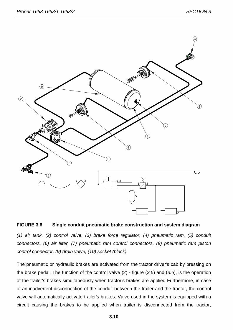
FIGURE 3.6 Single conduit pneumatic brake construction and system diagram
(1) air tank, (2) control valve, (3) brake force regulator, (4) pneumatic ram, (5) conduit
connectors, (6) air filter, (7) pneumatic ram control connectors, (8) pneumatic ram piston
control connector, (9) drain valve, (10) socket (black)
The pneumatic or hydraulic brakes are activated from the tractor driver's cab by pressing on
the brake pedal. The function of the control valve (2) - figure (3.5) and (3.6), is the operation
of the trailer's brakes simultaneously when tractor's brakes are applied Furthermore, in case
of an inadvertent disconnection of the conduit between the trailer and the tractor, the control
valve will automatically activate trailer's brakes. Valve used in the system is equipped with a
circuit causing the brakes to be applied when trailer is disconnected from the tractor,
1
2
3
4
5
6
7
8
9
10
1 2 1 1-21 2

SECTION 3 Pronar T653 T653/1 T653/2
3.11
compare with figure (3.9). When compressed air conduit is connected to the tractor, the
device automatically applying the brakes now changes its position to allow normal brake
operation.
FIGURE 3.7 Hydraulic brake construction and system diagram
(1) hydraulic cylinder, (2) hydraulic quick coupler, (3) hydraulic socket, (4) information decal
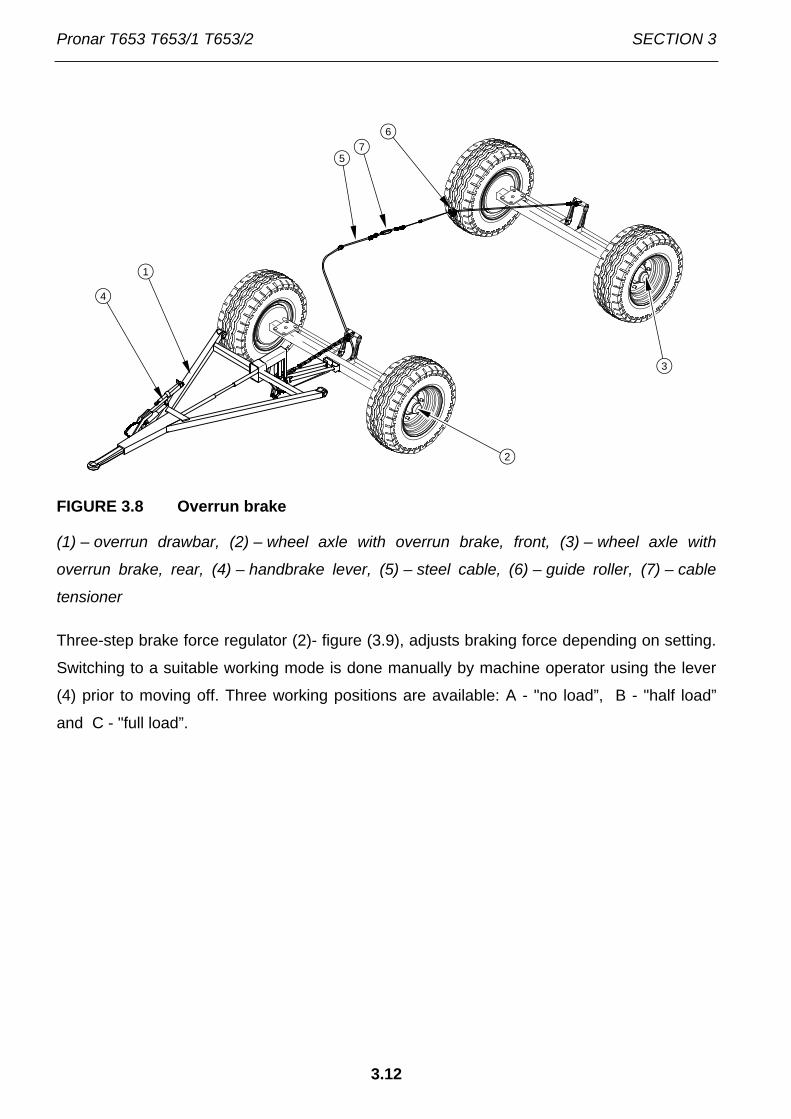
Overrun brake system design is shown in figure (3.8). Drawbar (1) with mobile pull rod as
standard is secured to the trailer turntable frame. Pull rods connected with set of cables to
front and rear axle which are available in overrun version. At the moment of activating the
brake in the tractor, the trailer exerts pressure on the tractor hitch, as a result of which the
drawbar pull rod moves in the body and draws the cable. Steel cables are connected with
axle expander levers, which activate trailer brakes. Overrun axles or equipped with
mechanism preventing blocking while reversing trailer.
1
2
3
4
Pronar T653 T653/1 T653/2 SECTION 3
3.12
FIGURE 3.8 Overrun brake
(1) – overrun drawbar, (2) – wheel axle with overrun brake, front, (3) – wheel axle with
overrun brake, rear, (4) – handbrake lever, (5) – steel cable, (6) – guide roller, (7) – cable
tensioner
Three-step brake force regulator (2)- figure (3.9), adjusts braking force depending on setting.
Switching to a suitable working mode is done manually by machine operator using the lever
(4) prior to moving off. Three working positions are available: A - "no load”, B - "half load”
and C - "full load”.
3
2
1
4
57
6

SECTION 3 Pronar T653 T653/1 T653/2
3.13
FIGURE 3.9 Control valve and brake force regulator
(1) control valve, (2) brake force regulator, (3) trailer parking brake release button, (4) work
selection regulator lever, (A) position "NO LOAD”, (B) position "HALF LOAD”, (C) position
"FULL�LOAD”
3.2.5 HYDRAULIC TIPPER SYSTEM
Hydraulic tipping system serves in automatic unloading of trailer by tipping the load box to the
rear or sideways. The hydraulic tipping system is supplied with oil from the tractor's hydraulic
system. Hydraulic oil manifold of the tractor's external hydraulic system is used to control the
load box tipping mechanism.
The trailer system consists of two independent circuits:
• circuit (A) - to supply the trailer's hydraulic ram cylinder,
• circuit (B) - to supply of the second trailer's hydraulic ram cylinder (if two trailers
are hitched to the tractor).
C
B
A
1
2
3
4

Pronar T653 T653/1 T653/2 SECTION 3
3.14
FIGURE 3.10 Hydraulic tipping system construction and diagram
(1) telescopic cylinder, (2) three-way valve, (3) cut-off valve, (4) quick coupler, (5) socket, (6)
control cable, (7) guide roller, (8), (9) information decal
Three-way valve (2) – figure (3.10) is used to activate these circuits. This valve's lever can
be placed in two positions:
• 1 - trailer's tipping circuit opened - circuit (A),
• 2 - second trailer's tipping circuit opened – circuit (B).
8
1
2
13
4
5
67
2
A
B
9

SECTION 3 Pronar T653 T653/1 T653/2
3.15
On the connection conduit, in the vicinity of socket (4) there is a decal (8) identifying the
supply conduit of the hydraulic system tipping circuit .
IMPORTANT!
Cut-off valve (3) – figure (3.10) limits the tipping angle of the load box when tipped to the sides and to the rear. The length of the control cable (6) controlling this valve is factory adjusted by the Manufacturer and must not be changed when the trailer is used.
TIP
The hydraulic system of the trailer is filled with L-HL32 Lotos hydraulic oil.
3.2.6 PARKING BRAKE
FIGURE 3.11 Parking brake housing with crank mechanism
(1) crank mechanism, (2) rear axle, (3) cable, (4) guide roller
The parking brake is for immobilising trailer while standing motionless. The brake crank
mechanism (1), is welded on the right lower longitudinal frame. Steel cable (3), routed
through guide roller (4), is connected with expanded levers of rear axle (2) by crank
1
2
3
4

Pronar T653 T653/1 T653/2 SECTION 3
3.16
mechanism. Tightening the cable (turning the crank clockwise) causes tilting of the expander
lever, which parts the jaws of the brake shoes immobilising the trailer.
In the case of the trailer version with overrun brake, the parking brake is activated by cable
tension using brake lever (4) – figure (3.8). The lever is secured to the overrun drawbar of the
trailer.
3.2.7 LIGHTING SYSTEM
FIGURE 3.12 Electrical system diagram
Marking according to table (3.2)
The trailer's electrical system is designed for supply of 12 V DC. Connection of the trailer's
electrical system with the tractor should be made through an appropriate connection lead.
PL
PP
ON2OK2
WG
WT
1
2
3
4
ZP
1
2
1
2
1
2
3
4
ZL
OTL
OTP
1 2 3 4 5 6 7 8
1
2
1
2
1
2
GP
GT

SECTION 3 Pronar T653 T653/1 T653/2
3.17
TABLE 3.2 List of electrical component markings
SYMBOL FUNCTION
ZP Rear right light combination group
ZL Rear left light combination group
GP Front seven pin socket
GT Rear seven pin socket
OTP Right registration plate light
OTL Left registration plate light
PP Front right parking light
PL Front left parking light
TABLE 3.3 Marking of connections of GT and GP sockets
MARKING FUNCTION
31 Weight
+ Power supply +12V (not used)
L Left indicator
54 STOP light
58L Rear left parking light
58R Rear right parking light
R Right indicator

Pronar T653 T653/1 T653/2 SECTION 3
3.18

SECTION
4
CORRECT USE
Pronar T653 T653/1 T653/2 SECTION 4
4.2
4.1 PREPARING FOR WORK BEFORE FIRST USE
4.1.1 CHECKING THE TRAILER AFTER DELIVERY
The manufacturer guarantees that the trailer is fully operational and has been checked
according to quality control procedures and is ready for normal use. This does not release
the user from an obligation to check the machine's condition after delivery and before first
use. The machine is delivered to the user completely assembled.
Before commencing work, machine operator must inspect the technical condition of the trailer
and prepare it for test start-up. The user must carefully read this Operator's Manual and
observe all recommendations, understand the design and the principle of machine operation.
IMPORTANT!
Before proceeding to hitching to tractor the user must carefully read this Operator's Manual and additional publications attached to machine and observe all recommendations.
External inspection
Check completeness of machine (standard and optional equipment).
Check condition of protective paint coat,
Inspect trailer's individual components for mechanical damage resulting from
incorrect transport (dents, piercing, bent or broken components).
Check technical condition of tyres and tyre pressure.
Check technical condition of elastic hydraulic conduits,
Check technical condition of pneumatic conduits,
Check that there are no hydraulic oil leaks.
Check electric lamps.
Check tipping ram cylinder for hydraulic oil leaks.
SECTION 4 Pronar T653 T653/1 T653/2
4.3
4.1.2 PREPARE A TRAILER FOR FIRST HITCHING TO TRACTOR
Preparation
Check all the trailer's lubrication points, lubricate the machine as needed
according to recommendations provided in section 5.
Check if the nuts and bolts fixing the wheels are properly tightened.
Drain air tank of the brake system.
Ensure that pneumatic, hydraulic and electric connections in agricultural
tractor are according to the requirements, if not the trailer should not be
hitched to the tractor.
Adjust the height of the drawbar setting or location of higher transport hitch.
A detailed description can be found in section 5.
Test drive
If all the above checks have been performed and there is no doubt as to the trailer's good
technical condition, it can be connected to tractor. Start the tractor, check all systems and
conduct test run of trailer without load (no load in load box). It is recommended that the
inspection is conducted by two people, one of which should always remain in the tractor's
cabin. Test start should be conducted according to the sequence shown below.
Connect trailer to appropriate hitch on agricultural tractor.
Connect brake, electrical and hydraulic system conduits.
Switch on individual lights, check correct operation of electrical system.
Turn hydraulic system return valve to position 1. Conduct test tipping of load
box sideways and backwards.
When moving off check if the main brakes operate correctly.
Perform test drive.

Pronar T653 T653/1 T653/2 SECTION 4
4.4
TIP
Service operation: hitching/unhitching from tractor, adjustment of draw bar position, tipping of load box etc. are described in detail in further parts of the instructions in sections 4 and 5.
The trailer may be hitched only when all preparatory activities including inspection of
technical condition have been completed satisfactorily. If during test run worrying symptoms
occur such as:
• noise and abnormal sounds originating from the abrasion of moving elements of
the trailer design,
• hydraulic oil leak,
• pressure drop in brake system,
• incorrect operation of hydraulic and/or pneumatic cylinders
or other faults, find the cause of the problem. If a fault cannot be rectified or the repair could
void the guarantee, please contact retailer for additional clarifications or to perform repair.
DANGER
Careless and improper use and operation of the trailer, and non-compliance with the recommendations given in this operator's manual is dangerous to your health. The trailer must never be used by persons who are not authorised to drive agricultural tractors, including children and people under the influence of alcohol or other drugs. Non-compliance with the safety rules of this Operator’s Manual can be dangerous to the health and life of the operator and others.
After completion of test drive check tightness of wheel nuts.
4.2 HITCHING AND DISCONNECTING FROM TRACTOR
Ensure that pneumatic, hydraulic and electric connections and the hitch of agricultural tractor
are according to the Manufacturer's requirements, if not the trailer should not be hitched to
the tractor.

SECTION 4 Pronar T653 T653/1 T653/2
4.5
In order to hitch the trailer to the tractor perform the actions below in the sequence
presented. Machine must be immobilised by parking brake.
Connection
Immobilise trailer with parking brake.
Pull brake mechanism to resistance in direction (A) – figure (4.1) – if
trailer is equipped with standard parking brake.
Pull brake mechanism (placed on draw bar) to resistance in direction
(A) – if trailer is equipped with overrun brake.
Position agricultural tractor directly in front of drawbar eye.
Set drawbar eye or height of upper transport hitch at such a height to enable
hitching the trailer.
Read section 5.
Reverse tractor, hitch trailer, check coupling lock protecting machine against
accidental unhitching.
If the agricultural tractor is equipped with an automatic coupler, ensure
that the hitching operation is completed and that drawbar eye is
secured.
Turn off tractor ignition. Ensure that unauthorised persons do not have access
to the tractor's cab.
Connect pneumatic system conduits (applies to two conduit systems):
Connect pneumatic conduit marked yellow with yellow socket in
tractor.
Connect pneumatic conduit marked red with red socket in tractor.
Connect pneumatic system conduits (applies to single conduit systems):
Connect pneumatic conduit marked black with black socket in tractor.
Connect hydraulic brake system (applies to trailer version with hydraulic
brake).
Hydraulic brake system conduit is marked with information decal (9) –
table (2.1).

Pronar T653 T653/1 T653/2 SECTION 4
4.6
Connect hydraulic tipping system conduit.
Hydraulic brake system conduit is marked with information decal (10)
– table (2.1).
Connect main conduit supplying electric lighting system.
DANGER
When hitching, there must be nobody between the trailer and the tractor. When hitching the machine, tractor driver must exercise caution and make sure that nobody is present in the hazard zone. When connecting the hydraulic conduits to the tractor, make sure that the tractor's hydraulic system and trailer are not under pressure. Ensure sufficient visibility during hitching.
During connection of braking system conduits (pneumatic double conduit) the correct
sequence of conduit connection is very important. First connect the yellow connector to
yellow socket in the tractor and only then connect the red connector to the red socket in the
tractor. Once the 2nd conduit is connected, the braking system will switch to normal mode of
operation (disconnection or interruption of the conduits causes the trailer's braking system
control valve to automatically apply brakes). Conduits are marked with coloured protective
covers, which identify the appropriate system conduit.
In the case of hitching a trailer with overrun brake it is required to set the height of the
drawbar exclusively with regard to the transport hitch when connecting hydraulic tipping
system and electrical system conduit.

SECTION 4 Pronar T653 T653/1 T653/2
4.7
FIGURE 4.1 Parking brake
(1) parking brake mechanism, (2) overrun drawbar, (3) parking brake lever, (A), (B)
movement direction of crank / parking brake lever
IMPORTANT!
Trailer may only be hitched to a tractor, which has the appropriate transport hitch, connection sockets for braking, hydraulic and electrical systems, and hydraulic oil in both machines is the same type and may be mixed. When hitching is completed, secure the electrical leads and hydraulic and braking system conduits in such a way that they do not become entangled in tractor's moving parts and are not at the risk of breaking or piercing when making turns.
IMPORTANT!
Ensure compatibility of oils in tractor hydraulic system and in the trailer hydraulic tipping system.
A
B
1
A B2
3

Pronar T653 T653/1 T653/2 SECTION 4
4.8
Disconnecting the trailer
In order to disconnect the trailer from the tractor carry out the following actions in the
following sequence:
Immobilise tractor and trailer with parking brake.
Turn off tractor ignition. Ensure that unauthorised persons do not have access
to the tractor's cab.
Disconnect all hydraulic tipping system conduits from tractor.
Disconnect electric lead.
Disconnect pneumatic system conduits (applies to double conduit systems):
Disconnect pneumatic conduit marked red.
Disconnect pneumatic conduit marked yellow.
Disconnect pneumatic system conduits (applies to single conduit systems):
Disconnect pneumatic conduit marked black.
Disconnect hydraulic brake system (applies to trailer version with hydraulic
brake).
Protect terminal ends with covers, Place conduit terminals in appropriate
sockets.
Disengage transport hitch and disconnect trailer drawbar from tractor hitch
and drive tractor away.
Place securing wedges under trailer wheel.
Wheel wedges shall be so placed that one is in front of the wheel and
the second is behind wheel of rear axle - see section 2.
DANGER
Exercise caution when disconnecting trailer from the tractor. Ensure good visibility. Unless it is necessary, do not go between tractor and trailer. Before disconnecting conduits and drawbar eye, close tractor cab and secure it against access by unauthorised persons. Turn off tractor ignition.
SECTION 4 Pronar T653 T653/1 T653/2
4.9
4.3 COUPLING AND UNCOUPLING SECOND TRAILER
A second trailer may only be connected, if it is a machine built on a dual axle chassis and if it
fulfils all the requirements specified in section 1. Coupling a second trailer to the assembly
requires experience in driving an agricultural tractor with a trailer. It is recommended while
coupling the second trailer to use the help of another person to guide the tractor driver.
DANGER
When hitching, there must be nobody between the trailers. Person assisting hitching up machines should stand outside the area of danger and be visible to the tractor driver at all times.
Coupling second trailer
The tractor with the coupled first trailer is positioned directly in front of the
drawbar of the second trailer.
Immobilise second trailer with parking brake.
Remove pin from the hitch of the first trailer.
Adjust the height of the drawbar of the second trailer in such a manner to
enable coupling the machines.
Reversing tractor, drive the rear hitch of the first trailer onto the drawbar of the
second trailer.
Insert drawbar pin and securing linchpin.
Connect conduits of pneumatic, hydraulic and electrical connections according
to instructions contained in section (4.2)
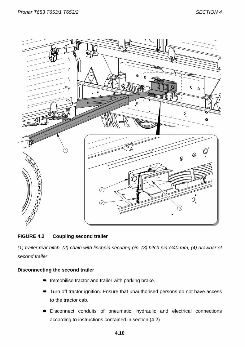
Pronar T653 T653/1 T653/2 SECTION 4
4.10
FIGURE 4.2 Coupling second trailer
(1) trailer rear hitch, (2) chain with linchpin securing pin, (3) hitch pin ∅40 mm, (4) drawbar of
second trailer
Disconnecting the second trailer
Immobilise tractor and trailer with parking brake.
Turn off tractor ignition. Ensure that unauthorised persons do not have access
to the tractor cab.
Disconnect conduits of pneumatic, hydraulic and electrical connections
according to instructions contained in section (4.2)
1
23
4

SECTION 4 Pronar T653 T653/1 T653/2
4.11
Remove linchpin from pin of the hitch of the first trailer. Remove drawbar pin
and drive tractor away.
IMPORTANT!
Do NOT hitch a second trailer constructed on any chassis except dual axle. Do NOT couple a second machine with trailer version T653/2 with overrun brake.
4.4 LOADING AND SECURING LOAD
4.4.1 GENERAL INFORMATION CONCERNING LOAD
Before beginning loading make certain that the load box side walls and slide gate are
properly closed and secured. The trailer must be positioned to travel forwards and be hitched
to the tractor. Loading should only take place, when trailer is placed on flat level surface and
hitched to tractor. If the trailer is equipped with tarpaulin cover, it should be rolled. If load
does not exert pressure on the side walls or extension walls, the linking cable can be
disengaged. In other cases it must be installed in cable release mechanism installed in the
side walls and extensions. Load box walls can be damaged if there is no linking cable.
Regardless of the type of load carried, the user is obliged to secure it in such a manner that
the load is unable to spread and cause contamination of the road. If this is impossible, do
NOT transport this type of load.
Materials, which in contact with painted or steel surfaces may cause damage, should be
transported in sealed packaging (sacks, boxes, barrels etc.), and after completing transport,
thoroughly wash out load box with water jet.
If the transported materials exert high local pressure on the load box platform it should be
protected against damage using thick planks, plywood or other materials of similar properties.
IMPORTANT!
Always aim at distributing the load uniformly in the load box. The trailer's maximum carrying capacity must not be exceeded.

Pronar T653 T653/1 T653/2 SECTION 4
4.12
With regard to the various densities of materials, using the total load box capacity may cause
exceeding permissible carrying capacity of the trailer. Guideline specific weight of selected
materials shown in table (4.1). It is necessary to pay particular attention not to overload the
trailer.
TABELA 4.1 Guideline weights volume of selected loads
TYPE OF MATERIAL VOLUME WEIGHT
kg/m3
Root crops: raw potatoes steamed crushed potatoes dried potatoes sugar beet - roots fodder beet - roots
700 - 820 850 - 950 130 - 150 560 - 720 500 - 700
Organic fertilisers: old manure mature manure fresh manure compost dry peat
700 - 800 800 - 900 700 - 750
950 – 1 100 500 - 600
Mineral fertilisers: ammonium sulphate potash salt super phosphate basic slag phosphate potassium sulphate kainite milled lime fertiliser
800 - 850 1,100 – 1,200 850 – 1,440
2,000 – 2,300 1,200 – 1,300 1,050 – 1,440 1,250 - 1,300
Building materials: cement dry sand wet sand solid bricks
1,200 – 1,300 1,350 – 1,650 1,700 – 2,050 1,500 – 2,100

SECTION 4 Pronar T653 T653/1 T653/2
4.13
TYPE OF MATERIAL VOLUME WEIGHT
kg/m3
hollow bricks stones soft wood hard sawn timber impregnated timber steel structures milled burnt lime cinders gravel
1,000 – 1,200 1,500 – 2,200
300 - 450 500 - 600 600 - 800
700 – 7,000 700 - 800 650 - 750
1,600 – 1,800
straw litter and bulk feeds meadow hay dried in the swath hay wilted in the swath hay in gathering trailer (dry wilted) wilted cut hay dry baled hay wilted baled hay stored dry hay stored cut hay clover (lucerne) wilted in the swath clover (lucerne) cut wilted on trailer clover (lucerne) wilted on gathering trailer dry stored clover cut dry stored clover dry straw in round bales damp straw in round bales cut damp straw in bulk trailer cut dry straw in bulk trailer cut dry straw in gathering trailer cut dry straw in stack baled straw (lightly crushed) baled straw (heavily crushed) cereal mass in round bales
10 - 18 15 - 25 50 - 80 60 - 70
120 - 150 200 - 290 50 - 90
90 - 150 20 - 25
110 - 160 60 - 100 40 - 60
80 - 140 8 - 15 15 - 20 50 - 80 20 - 40 50 - 90
40 - 100 80 - 90
110 - 150 20 - 25

Pronar T653 T653/1 T653/2 SECTION 4
4.14
TYPE OF MATERIAL VOLUME WEIGHT
kg/m3
cut cereal mass in bulk trailer cut cereal mass in gathering trailer green fodder in swath cut green fodder in bulk trailer green fodder in gathering trailer fresh beet leaves cut fresh beet leaves beet leaves in gathering trailer
35 - 75 60 - 100 28 - 35
150 - 400 120 - 270 140 - 160 350 - 400 180 - 250
concentrated feeds and mixed feeds: stored chaff pressed cake milled dry feed mixed feeds mineral mixtures ground oats wet sugar beet pulp pressed sugar beet pulp dry sugar beet pulp bran bone meal pasture salt (1)
molasses silage (pit silo) hay silage (tower silo)
200 - 225 880 – 1 000 170 - 185 450 - 650
1,100 – 1 300 380 - 410 830-1 000 750 - 800 350 - 400 320 - 600
700 – 1 000 1,100 – 1 200 1,350 – 1 450 650 – 1 050 550 - 750
Seeds and grains: beans mustard peas lentils runner beans barley clover
750 - 850 600 - 700 650 - 750 750 - 860 780 - 870 600 - 750 700 - 800
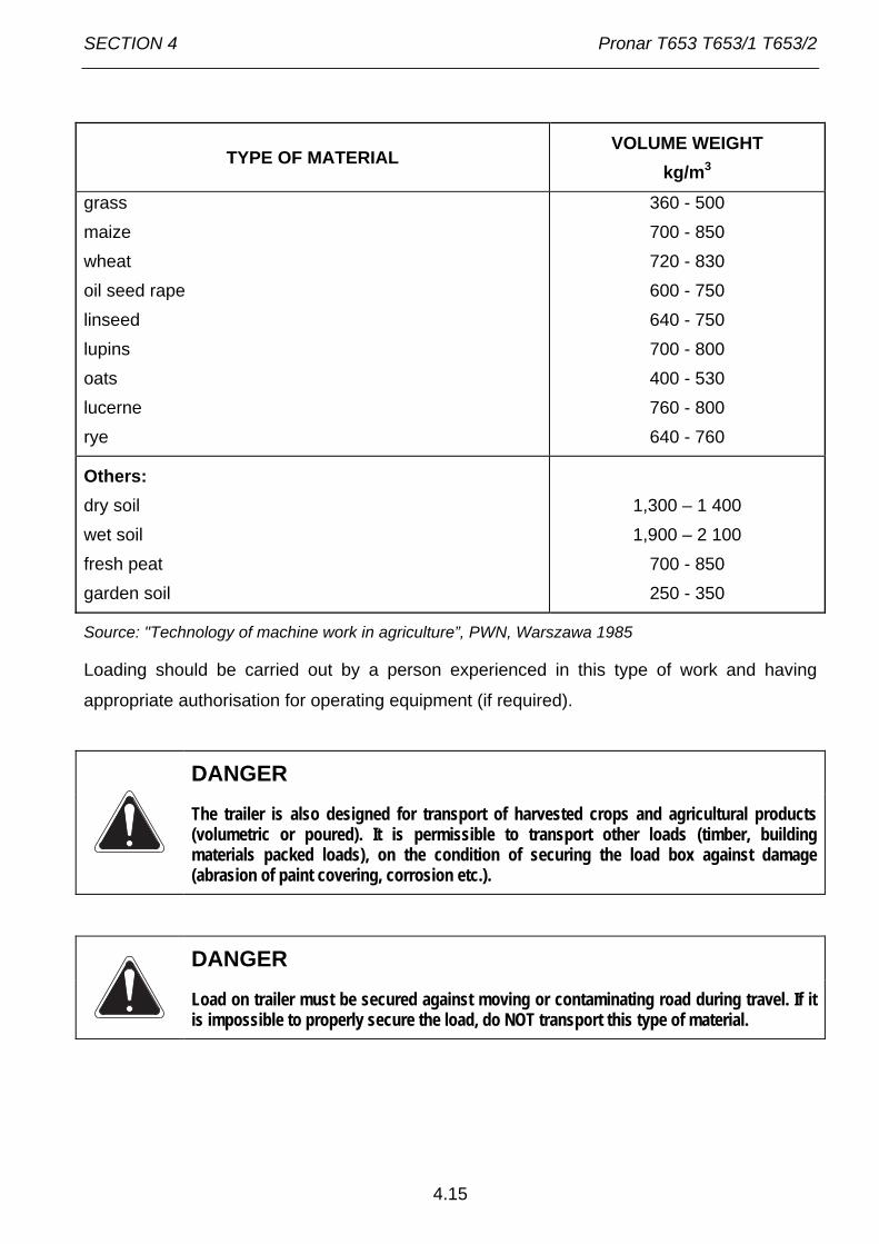
SECTION 4 Pronar T653 T653/1 T653/2
4.15
TYPE OF MATERIAL VOLUME WEIGHT
kg/m3
grass maize wheat oil seed rape linseed lupins oats lucerne rye
360 - 500 700 - 850 720 - 830 600 - 750 640 - 750 700 - 800 400 - 530 760 - 800 640 - 760
Others: dry soil wet soil fresh peat garden soil
1,300 – 1 400 1,900 – 2 100
700 - 850 250 - 350
Source: "Technology of machine work in agriculture”, PWN, Warszawa 1985
Loading should be carried out by a person experienced in this type of work and having
appropriate authorisation for operating equipment (if required).
DANGER
The trailer is also designed for transport of harvested crops and agricultural products (volumetric or poured). It is permissible to transport other loads (timber, building materials packed loads), on the condition of securing the load box against damage (abrasion of paint covering, corrosion etc.).
DANGER
Load on trailer must be secured against moving or contaminating road during travel. If it is impossible to properly secure the load, do NOT transport this type of material.

Pronar T653 T653/1 T653/2 SECTION 4
4.16
Loose bulk material
Loading bulk materials is normally conducted with the use of loaders or conveyors and
possibly loading manually. Bulk materials may not protrude beyond the outline of sides or
extensions. On completion of loading, the load should be evenly spread over the whole
surface of the load box. During loading materials sides and extensions should be connected
with linking cable. Secure cable release mechanism with linchpin.
Oilseed rape or seeds of other plants of very small size or powder materials can be
transported provided the load box is properly sealed in places where gaps are bigger than
the seed diameter or other carried material. Profiled rubber seals, silicone sealers, plastic
wrap, rope or textile materials are recommended materials to provide sealing of the load box.
Additionally it is essential to protect load with tarpaulin cover. It protects the load against
spilling during travel, being blown away by the wind and also protects load against moisture,
which is particularly dangerous in the case of bulk materials. They may absorb a significant
amount of water, which may increase the bulk of the load during travel. In extreme cases the
gross weight of the trailer may exceed the permissible vehicle gross weight.
Some bulk loads (e.g. building materials, such as gravel or slag) may cause more rapid
damage to paintwork.
Loads of pieces or solid lumps
Loads of pieces or solid lumps are generally hard materials of significantly greater
dimensions than bulk loads (stones, coal, bricks and ballast). These materials without prior
preparation of the load box may cause indentation of the floor or sidewalls and abrasion of
paintwork. In order to protect it, lay thick plywood, hard particle board, thick planks or other
materials of similar properties on the load box platform and shield sides and extensions. Non-
compliance with the instructions provided could invalidate the guarantee. Loading of material
in pieces or solid lumps must be from a low height. The load must not fall with great force on
the floor of the load box, even if it is protected.
Hazardous loads
According to the European ADR agreement concerning the international road transport of
hazardous materials, the transport of this type of load (defined in detailed by this agreement)
is forbidden with the use of agricultural trailers. The only exception are plant protection
materials and artificial fertilisers, which may be transported on agricultural trailers on the

SECTION 4 Pronar T653 T653/1 T653/2
4.17
condition that they are transported in the appropriate packaging and in quantities envisaged
by the ADR agreement.
DANGER
If it is necessary to carry permitted hazardous materials, acquaint yourself with the regulations concerning transport of hazardous materials in force in the given country and also the regulations of the ADR agreement. It is absolutely essential to carefully read the information leaflets provided by the load manufacturer, and to observe the instructions for transporting and handling the load. Ensure whether during loading work it is necessary to apply additional personal protection (masks, rubber gloves etc.)
High volume loads
High-volume loads (light with a high volume), such as hay, straw bales - rectangular or round,
green fodder etc, are recommended to be loaded with the aid of the appropriate mechanical
fittings: bail grabs, forks etc. The load may be loaded even higher than the load box
extensions but taking care about trailer stability and proper securing and protection of load.
Remember that higher loading has a negative effect on trailer stability.
Loads in packaging
Loads transported in packaging (boxes, sacks), must be laid closely side-by-side beginning
from the front side of the trailer. If it is essential to lay several layers, particular groups should
be stacked alternately (in block system). The load must be laid tightly together and on the
whole surface of the trailer floor. Otherwise, during travel the load will move. With regard to
the trailer construction (adaptation of the load box to the transport of agricultural crops and
products, lack of load securing points), materials in packaging may not be loaded above the
top of the walls or extensions of load box. If the trailer is equipped with net extensions, the
height of the load layer may not be higher than 500 mm, that is it may not exceed the upper
edge of the sides. A higher load level may move during travel and cause significant damage
to the net extensions and the load may spill.
Pronar T653 T653/1 T653/2 SECTION 4
4.18
DANGER
If there is a danger of load packaging moving, do NOT transport this type of material. A moving load constitutes a serious hazard during travel for the tractor driver and other road users.
Materials which may cause corrosion of steel, chemical damage or react in any other way
negatively affecting the trailer structure may be transported only on condition of appropriate
load preparation. Materials must be tightly packed (in plastic foil sacks, plastic containers
etc.).During transport packaging contents may not come into contact with load box therefore
ensure the appropriate tightness of containers.
With regard to the diversity of materials, tools, means of securing and getting a load it is
impossible to describe all means of loading. While working be guided by caution and own
experience. The trailer user must carefully read the regulations concerning road transport
and comply with them.
DANGER
Overloading the trailer, erroneous loading and securing of the load is the most frequent cause of accidents during transport. The load must be arranged in such a way that it does not threaten the stability of the trailer, and does not hinder driving. Ensure that during unloading / loading or raising the load box nobody is near the trailer. Before tipping load box ensure that there is visibility and make certain that there are no bystanders.
DANGER
The trailer is not intended to transport people, animals or hazardous materials (with the exception of loads specified in section 4.4). The arrangement of the load may not cause an overload on the axle of the trailer.

SECTION 4 Pronar T653 T653/1 T653/2
4.19
4.5 TRANSPORTING LOADS
When driving on public or private roads, respect the road traffic regulations, exercise caution
and prudence. Listed below are the key guidelines for driving the tractor and trailer
combination.
• Before moving off make sure that there are no bystanders, especially children,
near the trailer or the tractor. Take care that the driver has sufficient visibility.
• Make sure that the trailer is correctly attached to the tractor and tractor's hitch is
properly secured.
• The trailer must not be overloaded, loads must be uniformly distributed so that the
maximum permissible axle loads are not exceeded. The trailer's maximum
carrying capacity must not be exceeded as this can damage the trailer and pose a
risk to the operator or other road users.
• Permissible design speed and maximum speed allowable by road traffic law must
not be exceeded. The towing speed should be adapted to the current road
conditions, load carried by the trailer, road surface conditions and other relevant
conditions.
• Trailer may be towed on slopes of up to 8° and unloading must take place only on
a level surface.
• When not connected to the tractor, the trailer must be immobilised using parking
brake and possibly also with wedges or other objects without sharp edges placed
under the front and back wheels. Do NOT leave unsecured trailer. In the event of
machine malfunction, pull over on the hard shoulder avoiding any risk to other
road users and position reflective warning triangle according to traffic regulations.
• When driving on public roads trailer must be marked with a slow-moving vehicle
warning sign attached to the rear wall of load box, if the trailer is the last vehicle in
the group.
• While driving on public roads the trailer must be fitted with a certified or
authorised reflective warning triangle.
• When driving, comply with all road traffic regulations, indicate an intention to turn
using indicator lamps, keep all road lights and indicator lights clean at all times

Pronar T653 T653/1 T653/2 SECTION 4
4.20
and ensure they are in good condition. Any damaged or lost lamps or indicator
lights must be immediately repaired or replaced.
• Avoid ruts, depressions, ditches or driving on roadside slopes. Driving across
such obstacles could cause the trailer or the tractor to suddenly tilt. This is of
special importance because loaded trailer's centre of gravity is higher (especially
a high volume load), which reduces safety. Driving near ditches or channels is
dangerous as there is a risk of the wheels sliding down the slope or the slope
collapsing.
• Speed must be sufficiently reduced before making a turn or driving on an uneven
road or a slope.
• When driving, avoid sharp turns especially on slopes.
• Please note that the braking distance of tractor and trailer combination is
substantially increased at higher speeds and loads carried in the trailer.
• Monitor trailer's behaviour when travelling on an uneven terrain, and adjust driving
speed to road conditions, slow down early enough when turning.
IMPORTANT!
Prior to moving off with the trailer hitched, check the following: • pins connecting the load box with the lower frame are secured against falling
out,
• side wall hinge pins are protected against falling out.
Travel with a high-volume load by ruts, ditches roadside slopes etc.constitutes a great risk of overturning the trailer. Exercise caution when working.
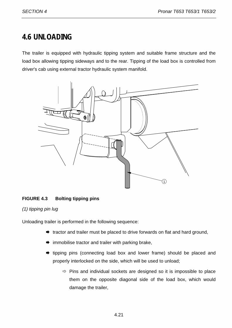
SECTION 4 Pronar T653 T653/1 T653/2
4.21
4.6 UNLOADING
The trailer is equipped with hydraulic tipping system and suitable frame structure and the
load box allowing tipping sideways and to the rear. Tipping of the load box is controlled from
driver's cab using external tractor hydraulic system manifold.
FIGURE 4.3 Bolting tipping pins
(1) tipping pin lug
Unloading trailer is performed in the following sequence:
tractor and trailer must be placed to drive forwards on flat and hard ground,
immobilise tractor and trailer with parking brake,
tipping pins (connecting load box and lower frame) should be placed and
properly interlocked on the side, which will be used to unload;
Pins and individual sockets are designed so it is impossible to place
them on the opposite diagonal side of the load box, which would
damage the trailer,
1

Pronar T653 T653/1 T653/2 SECTION 4
4.22
lug (1) correct bolting of pin is directed vertically (downwards) – figure
(4.3),
FIGURE 4.4 Locks of box sides and extensions
(1) left wall locking lever, (2) rear wall locking lever, (3) side wall lock (rear left), (4) rear wall
lock (left), (5) lateral lock
open appropriate closures of sides and/or extensions and side wall or rear wall
locks or open rear chute sliding gate (depending on the direction in which
unloading should take place);
during opening exercise caution, because the load may exert great
pressure on the sides.
Place the control lever controlling the hydraulic tipping system circuits in
position 1 -- tipping of the first trailer,
Using the manifold lever in the operator's cabin to initiate tipping of the load
box,
after unloading, lower load box, clean the residual material from the load box
edges and walls,
1
2
3
4
5

SECTION 4 Pronar T653 T653/1 T653/2
4.23
close and secure the walls and wall extensions or chute opening,
before moving off make sure that tipping pins are in correct position, i.e. with
the handle facing downward.
If a second trailer is hitched, it should be unloaded only when the load box of the first trailer
has been lowered and the hydraulic tipping system control lever is placed in position 2 --
tipping of the second trailer.
DANGER
Tipping the load box must be done on hard and level ground. Use only original pins with a lug or handle. Using third-party pins could damage the trailer. Tipping pins must be correctly interlocked. When opening load box side wall locks take particular care, because of the pressure of the load on the wall.
Rear load box wall is equipped with chute slide gate (1) – figure (4.5) and chute opening (2)
(optional equipment) which is used for unloading of loose materials. Chute design allows very
accurate dosing of the material to packaging (sacks, boxes etc). The opening gap can be
controlled using lever (3). In order to do that loosen the bolt interlocking slide gate (4), open
the slide as required and lock again using the bolt. When unloading through the chute do not
open wall locks or wall extension locks and tipping of the load box must be done very slowly
and without jerking. Raising the load box quickly will exert large pressure on the rear part of
the load box due to displacement of the carried material and could compromise trailer's
stability.

Pronar T653 T653/1 T653/2 SECTION 4
4.24
FIGURE 4.5 Chute
(1) chute slide gate, (2) chute, (3) lever, (4) locking bolt
DANGER
When closing the rear grain chute gate or the walls take particular care to avoid crushing fingers.
Trailer with net extensions may only be unloaded by tipping load box to the rear.
1 2
34

SECTION 4 Pronar T653 T653/1 T653/2
4.25
DANGER
Bulk materials loaded in excess of 1 m can be unloaded by tipping the load box to the rear only. Do NOT jerk the trailer forwards if load is bulky or reluctant to pour and does not unload. Ensure that during unloading nobody is near tipped load box or load material pouring out. Tipping may only be performed when trailer is hitched to tractor. Do NOT tip load box in strong gusty winds conditions. Do NOT move off or drive when load box is raised.
While unloading bulky materials be especially careful. Do NOT tip load box on uneven or wet
ground and move and jerk trailer during unloading. Bulky materials are normally difficult to
unload therefore proceed cautiously and patiently. Careless operation of trailer may pose a
danger to operators and bystanders can also cause damage to the machine.
4.7 PROPER USE AND MAINTENANCE OF TYRES
• When working on the tyres, wedges or other objects without sharp edges should
be placed under the wheels of the trailer to prevent it from rolling. The wheel can
be taken off only when the trailer is not loaded.
• Repair work on the wheels or tyres should be carried out by persons trained and
entitled to do so. This work should be carried out using appropriate tools.
• Inspection of nut tightening should be carried out after first use of trailer, after first
travel with loading and then after 6 months use. In the event of intensive work
checking the nut tightening should be done not less frequently than each100
kilometres. The above actions should be repeated individually if a wheel has been
removed from the wheel axle.
• Regularly check and maintain correct pressure in tyres according to Operator's
Manual (especially if trailer is not used for a longer period).
• Pressure and tyres should be also checked after the whole day of intensive work.
Please note that higher temperatures could raise tyre pressure by as much as 1
bar. At high temperatures and pressure, reduce load or speed.
Pronar T653 T653/1 T653/2 SECTION 4
4.26
• Do not release air from warm tyres to adjust the pressure or the tyres will be
underinflated when temperatures return to normal.
• Protect valves using suitable caps to avoid soiling.
• Do not exceed the trailer's maximum design speed.
• When trailer is operated all day, stop working for a minimum of one hour in the
afternoon.
• Adhere to 30 minutes rest for cooling tyres after driving 75 km or after 150
minutes continuous travel depending on which occurs first.
• Avoid potholes, sudden manoeuvres or high speeds when turning.

SECTION
5
TECHNICAL OPERATION
Pronar T653 T653/1 T653/2 Section 5
5.2
5.1 PRELIMINARY INFORMATION
When using the trailer, regular inspections of its technical condition are essential and the
performance of maintenance procedures, which keep the machine in good technical
condition. In connection with this the user of the trailer is obliged to perform all the
maintenance and adjustment procedures defined by the Manufacturer.
Repairs during the guarantee period may only be performed by authorised service points.
Detailed procedures and extents of functions are described in this section, which the user
may perform with his own resources. In the event of unauthorised repairs, changes to factory
settings and other actions, which are not regarded as possible for the trailer operator to
perform, the user shall invalidate the guarantee.
5.2 SERVICING BRAKES AND AXLES
5.2.1 PRELIMINARY INFORMATION
Work connected with the repair, change or regeneration of axle and brakes elements should
be entrusted to specialist establishments, having the appropriate technology and
qualifications for this type of work.
The duties of the user are limited to:
• initial inspection of axle brakes,
• inspection and adjustment of loose play of axle bearings,
• mounting and dismounting wheel inspection of wheel tightening,
• checking air pressure, evaluating technical condition of wheels and tyres,
• mechanical brakes adjustment,
• change of parking brake cable and adjustment of cable tension.
Procedures connected with:
• changing grease in axle bearings,
• changing bearings, hub seals,
• changing brake linings, repairing brake,

Section 5 Pronar T653 T653/1 T653/2
5.3
may be performed by specialist workshops.
DANGER
Do NOT use the trailer when brake system is unreliable.
5.2.2 INITIAL INSPECTION OF AXLE BRAKES,
After purchasing trailer, the user is responsible for general checking of brake system of trailer
axles.
Initial inspection of axle brakes must be conducted: • after first use,
• after first travel with load.
Inspection procedures
Hitch trailer to tractor and place wedges under rear trailer wheel.
Engage and release in turn the main brake and then the trailer parking brake.
Main brake and parking brake should be engaged and released
without great resistance and severity.
Check means of securing cylinder and return springs.
Check cylinder movement and correct return of piston to start position.
The help of a second person is required, who shall engage trailer
brake.
Check if axle elements are in place, (cotter pins in castellated nuts, expansion
rings etc.).
Check hydraulic cylinders or pneumatic cylinders for tightness - compare
sections 5.3.2 and 5.4.2.

Pronar T653 T653/1 T653/2 Section 5
5.4
5.2.3 CHECK WHEEL AXLE BEARINGS LOOSENESS
FIGURE 5.1 Lifting jack support point
(1) axle, (2) leaf spring shock absorber, (3) U bolt.
Preparation procedures
Hitch trailer to tractor, braking tractor with parking brake.
Park tractor and trailer on hard level ground.
Position tractor to drive straight forward (front trailer axle may not be
turned).
Place securing wedges under trailer rear wheel. Ensure that trailer shall not
move during inspection.
Raise front wheel (opposite to the side where wedges are placed).
1 2 3

Section 5 Pronar T653 T653/1 T653/2
5.5
The lifting jack should be placed under the axle between U bolts (3)
figure (5.1) securing axle (1) to shock absorber leaf springs (2), or as
near as possible to leaf spring mounting. Recommended support
points are marked with arrows. Lifting jack must be suited to weight of
trailer.
Check wheel axle bearings looseness
Turning the wheel slowly in both directions check that movement is smooth
and that the wheel rotates without excessive resistance.
Turn the wheel so that it rotates very quickly, check that the bearing does not
make any unusual sounds.
Turning the wheel try to detect looseness.
You may use a lever placed under the wheel supporting the other end
on the floor.
Repeat procedure to each wheel individually, remembering that the jack must
be on the side opposite to the wedges.
If slack is felt, adjust bearing. Unusual sounds coming from bearing may be symptoms of
excess wear, dirt or damage. In such an event the bearing, together with sealing ring, should
be replaced with new parts, or cleaned and greased again During inspection of bearings
ensure that possibly detected looseness comes from the bearing and not from the
suspension system (e.g. looseness of leaf spring pins etc.).
TIP
Damaged hub cover or lack of hub cover causes penetration of contamination and dampness to hub, which causes significantly faster wear of bearing and hub seals. Bearing life is dependent on working conditions of trailer, loading, speed of travel and lubrication conditions.
Check condition of hub cover, if necessary replace with new cover. Inspection of bearing
looseness may only and exclusively be conducted, when the trailer is hitched to a tractor, and
the load box is empty.

Pronar T653 T653/1 T653/2 Section 5
5.6
Check wheel axle bearings looseness • after travelling the first 1,000 km,
• after intensive use of trailer,
• every six months use or every 25,000 km.
DANGER
Before commencing work the user must read the instructions for lifting and adhere to the manufacturer's instructions. The lifting jack must be stably supported by the ground and the axle. Ensure that trailer shall not move during inspection of bearing looseness of axles.
5.2.4 ADJUSTMENT OF WHEEL AXLE BEARINGS LOOSENESS
Preparation procedures
Prepare tractor and trailer for adjustment procedures according with
description provided in section 5.2.3.
Adjustment of road wheel axle bearings
Take off hub cover (1) - figure (5.2).
Take out split cotter pin (3) securing castellated nut (2).
Tighten castellated nut in order to eliminate looseness.
Wheel should rotate with insignificant resistance.
Unscrew nut (not less than1/3 rotation) to cover the nearest thread groove
with alignment to opening in wheel stub axle. Wheel should rotate with
insignificant resistance.
Nut may not be excessively tightened. Do not apply excessive
pressure with regard for deterioration of bearing working conditions.
Secure castellated nut with cotter pin and mount hub cap.
Delicately tap hub cap with rubber or wooden hammer.

Section 5 Pronar T653 T653/1 T653/2
5.7
FIGURE 5.2 Adjustment of road wheel axle bearings
(1) hub cover, (2) castellated nut, (3) securing split cotter pin
The wheel should turn smoothly without stiffness or detectable resistance not originating from
abrasion of brake shoes in brake drum. Adjustment of bearing looseness may only and
exclusively be conducted, when the trailer is hitched to a tractor, and the load box is empty.
TIP
If the wheel is dismounted, bearing looseness is easy to check and adjust.
5.2.5 MOUNTING AND DISMOUNTING WHEEL, INSPECTION OF WHEEL NUT TIGHTENING.
Dismounting wheel
Immobilise trailer with parking brake.
Place securing wedges under trailer rear wheel.
Ensure that trailer shall not move during wheel dismounting.
A
B
12
3

Pronar T653 T653/1 T653/2 Section 5
5.8
Loosen wheel nuts according to sequence given in figure (5.3).
Place lifting jack and lift trailer.
Dismount wheel.
Mount wheel
Clean axle pins and nuts of dirt contamination.
Do not grease thread of nuts and pins.
Check condition of pins and nuts, if necessary replace.
Place wheel on hub, tighten nuts so that adjoins hub exactly.
Lower trailer, tighten nuts according to recommended torque and given
sequence.
TIP
Wheel nuts should be tightened using a torque of 270 Nm - nuts M18x1.5.
Tightening nuts
Nuts should be tightened gradually diagonally, (in several stages, until obtaining the required
tightening torque) using a torque spanner. If a torque spanner is not available, one may use
an ordinary spanner. The arm of the spanner (L) figure (5.3) should be selected according to
the weight of the person (F) tightening the nut. Remember that this method of tightening is
not as accurate as the use of a torque spanner.

Section 5 Pronar T653 T653/1 T653/2
5.9
FIGURE 5.3 Sequence of nut tightening
(1) - (6) sequence of nut tightening, (L) spanner length, (F) user weight
Checking wheel axle tightening: • after first use,
• after first travel with load,
• after travelling the first 1,000 km,
• every six months use or every 25,000 km.
In the event of intensive work checking the nut tightening should be done at least every 100 kilometres. The above actions should be repeated individually if a wheel has been removed from the wheel axle.
IMPORTANT!
Axle nuts may not be tightened with impact wrench, because of danger of exceeding permissible tightening torque, the consequence of which may be breaking the thread connection or breaking off the hub pins. The greatest precision is achieved by use of a torque spanner. Before commencing work, ensure that correct tightening torque value is set.
L
F1
2
34
5
6
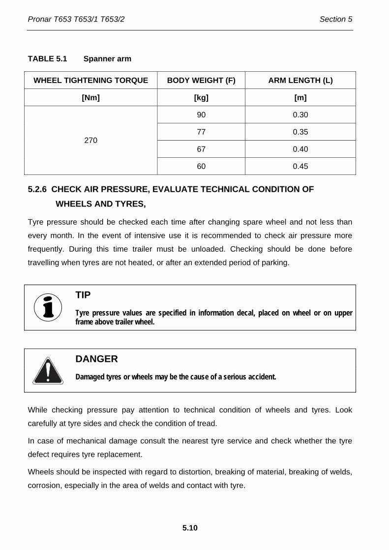
Pronar T653 T653/1 T653/2 Section 5
5.10
TABLE 5.1 Spanner arm
WHEEL TIGHTENING TORQUE BODY WEIGHT (F) ARM LENGTH (L)
[Nm] [kg] [m]
90 0.30
77 0.35
67 0.40 270
60 0.45
5.2.6 CHECK AIR PRESSURE, EVALUATE TECHNICAL CONDITION OF WHEELS AND TYRES,
Tyre pressure should be checked each time after changing spare wheel and not less than
every month. In the event of intensive use it is recommended to check air pressure more
frequently. During this time trailer must be unloaded. Checking should be done before
travelling when tyres are not heated, or after an extended period of parking.
TIP
Tyre pressure values are specified in information decal, placed on wheel or on upper frame above trailer wheel.
DANGER
Damaged tyres or wheels may be the cause of a serious accident.
While checking pressure pay attention to technical condition of wheels and tyres. Look
carefully at tyre sides and check the condition of tread.
In case of mechanical damage consult the nearest tyre service and check whether the tyre
defect requires tyre replacement.
Wheels should be inspected with regard to distortion, breaking of material, breaking of welds,
corrosion, especially in the area of welds and contact with tyre.

Section 5 Pronar T653 T653/1 T653/2
5.11
Technical condition and appropriate maintenance significantly extends the life of these
elements and ensures appropriate level of safety to trailer users.
Checking tyre pressure and steel rims: • every 1 month of use,
• if needed.
5.2.7 MECHANICAL BRAKES ADJUSTMENT,
During use of trailer abrasive friction covering of brake drums is subject to wear. Piston
stroke extends, and exceeding braking force limiting value declines.
Adjustment must be made when:
• piston stroke amounts to 2/3 of maximum stroke,
• expansion levers are not set in parallel to each other during braking,
• repairs are made to braking system.
Trailer wheels must brake simultaneously. Brakes adjustment involves changing the setting
of the expander arm (1) (FIGURE 5.4), in relation to expander shaft (2).
Required service actions
Dismount cylinder fork mounted to expander arm (1).
Dismantle expander ring (4) and washer (3).
Mark position of expander arm (1) with regard to the shaft (2).
Dismantle arm and set it in the appropriate position.
in direction (A), if braking is too early,
in direction (B), if breaking is too late.
Position washer and expander ring. Check if elements are correctly
positioned.

Pronar T653 T653/1 T653/2 Section 5
5.12
FIGURE 5.4 Adjustment of axle mechanical brakes
(1) expander arm, (2) expander shaft, (3) washer, (4) expander ring
Adjustment should be conducted separately for each wheel. Expander arm (1) should be
moved by one notch in chosen direction. If the extent of cylinder action is still incorrect, move
the lever again. After proper brake adjustment, at full braking the axle shaft expander should
create an angle of 90° with the cylinder piston, and the stroke should amount to approximately
half the length of the total stroke of the piston. After brake release expander arms may not be
supported on any structural elements, because too little withdrawal of a piston ram may
cause abrasion of brake shoes in drum and result in overheating trailer brakes. Expander
arms, placed on one axle, must be positioned in parallel with regard to each other at full
braking. If this is not so, adjust the position of the lever, which has the longer stroke.
During dismantling of cylinder fork remember or mark the original setting of the cylinder fork
pin. The mounting position is selected by the Manufacturer and may not be changed.
A
B
123
4
180150
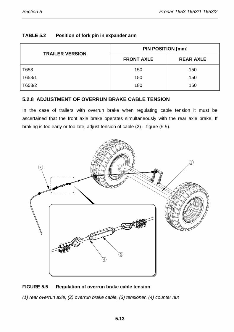
Section 5 Pronar T653 T653/1 T653/2
5.13
TABLE 5.2 Position of fork pin in expander arm
PIN POSITION [mm] TRAILER VERSION.
FRONT AXLE REAR AXLE
T653 T653/1 T653/2
150 150 180
150 150 150
5.2.8 ADJUSTMENT OF OVERRUN BRAKE CABLE TENSION
In the case of trailers with overrun brake when regulating cable tension it must be
ascertained that the front axle brake operates simultaneously with the rear axle brake. If
braking is too early or too late, adjust tension of cable (2) – figure (5.5).
FIGURE 5.5 Regulation of overrun brake cable tension
(1) rear overrun axle, (2) overrun brake cable, (3) tensioner, (4) counter nut
12
34

Pronar T653 T653/1 T653/2 Section 5
5.14
Required service actions
Loosen counter nut (4) of tensioner.
Adjust cable length (2)
Tighten cable (2), if rear axle brake operates after front axle brake.
Loosen cable (2), if rear axle brake operates before front axle brake.
Tighten nut (4), check brake action.
If problem continues repeat all actions.
Checking and adjustment of main brake: • every 12 months,
• if needed.
Brake repairs, changes of brake linings etc. may be only undertaken in authorised service
points. Making unauthorised repairs and modifications by the user voids the guarantee.
Among the service operations, which may be performed by the trailer user, there is only
brake adjustment by changing the setting of expander arms.
5.2.9 CHANGE OF PARKING BRAKE CABLE AND ADJUSTMENT OF CABLE TENSION.
Proper operation of the parking brake is dependent on the effectiveness of the rear axle
brake and the correct brake cable tension.
Change parking brake cable
Hitch trailer to tractor. Park trailer and tractor on level surface.
Place securing wedges under trailer rear wheel.
Loosen nut (4) of cable clamps.
Dismantle cable (2).
Lubricate parking brake mechanism and pins of cable guide rollers.
Install new cable, adjust cable tension.
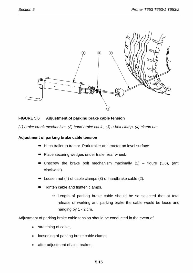
Section 5 Pronar T653 T653/1 T653/2
5.15
FIGURE 5.6 Adjustment of parking brake cable tension
(1) brake crank mechanism, (2) hand brake cable, (3) u-bolt clamp, (4) clamp nut
Adjustment of parking brake cable tension
Hitch trailer to tractor. Park trailer and tractor on level surface.
Place securing wedges under trailer rear wheel.
Unscrew the brake bolt mechanism maximally (1) – figure (5.6), (anti
clockwise).
Loosen nut (4) of cable clamps (3) of handbrake cable (2).
Tighten cable and tighten clamps.
Length of parking brake cable should be so selected that at total
release of working and parking brake the cable would be loose and
hanging by 1 - 2 cm.
Adjustment of parking brake cable tension should be conducted in the event of:
• stretching of cable,
• loosening of parking brake cable clamps
• after adjustment of axle brakes,
21 3
4

Pronar T653 T653/1 T653/2 Section 5
5.16
• after repairs to axle brake system,
• after repairs in parking brake system.
Before commencing adjustment make certain that the main break is correctly regulated and
is functioning properly.
Adjustment of parking brake (in trailer version with overrun brake), is unnecessary if the main
brake (overrun) operates properly.
Checking and adjustment of parking brake: • every 12 months,
• if needed.
5.3 PNEUMATIC SYSTEM OPERATION
5.3.1 PRELIMINARY INFORMATION
Work connected with the repair, change or regeneration of system components (brake
cylinders, conduits, control valve, braking force regulator etc.) should be entrusted to
specialist establishments, having the appropriate technology and qualifications for this type of
work.
The duties of the operator connected with the pneumatic system include:
• inspecting and checking air tightness of pneumatic system.
• cleaning the air filter (filters),
• draining water from air tank,
• cleaning drain valve,
• cleaning and maintaining pneumatic conduit connections,
DANGER
Do NOT use the trailer when brake system is unreliable.

Section 5 Pronar T653 T653/1 T653/2
5.17
5.3.2 INSPECTING AND CHECKING AIR TIGHTNESS OF PNEUMATIC SYSTEM.
Checking hydraulic system tightness
Hitch trailer to tractor.
Immobilise tractor and trailer with parking brake. Place securing wedges under
trailer rear wheel.
Start tractor in order to supplement air in trailer brake system tank.
In single conduit systems air pressure should amount to approx. 5.8
bar.
In double conduit systems air pressure should amount to approx. 8
bar.
Turn off tractor ignition.
Check system components by releasing brake pedal in tractor.
Give particular attention to conduit connections and brake cylinders.
Repeat system check with depressed tractor brake pedal.
The help of a second person is required.
In the event of the appearance of leaks, compressed air will reach places of damage on the
exterior, with a characteristic hiss. Lack of system tightness may be exposed by covering
checked elements with washing fluid or other foaming preparations, which will not react
aggressively with system components. It is recommended to supply preparations
commercially available designed to facilitate discovering air leaks. Damaged components
should be replaced or repaired. If the leaks appear in connections, the user may tighten the
connections. If air continues to escape replace connection component or seal.
Check system tightness • after travelling the first 1,000 km,
• each time after making repairs or changing system components,
• annually.

Pronar T653 T653/1 T653/2 Section 5
5.18
Visual assessment of system
During tightness inspection attention should additionally be given to technical condition and
degree of cleanness of the system components. Contact of pneumatic conduit seals etc. with
oil, grease, petrol etc. may cause damage and accelerate the ageing process. Bent conduits,
permanently deformed, cut or worn should be replaced.
Visual assessment of system • Conduct inspection of system at the same time as when checking tightness.
IMPORTANT!
Repair, exchange or regeneration of pneumatic system components may only be performed in a specialised workshop.
5.3.3 CLEANING THE AIR FILTERS
Depending on trailer working conditions, but not less than once in three months, take out and
clean air filter inserts, which are placed in pneumatic system connection conduits. Inserts are
used many times and are not subject to changing unless they are mechanically damaged.
DANGER
Before proceeding to dismantle filter, reduce pressure in supply conduit. While disengaging filter slide gate, hold cover with other hand. Stand away from filter cover vertical direction.
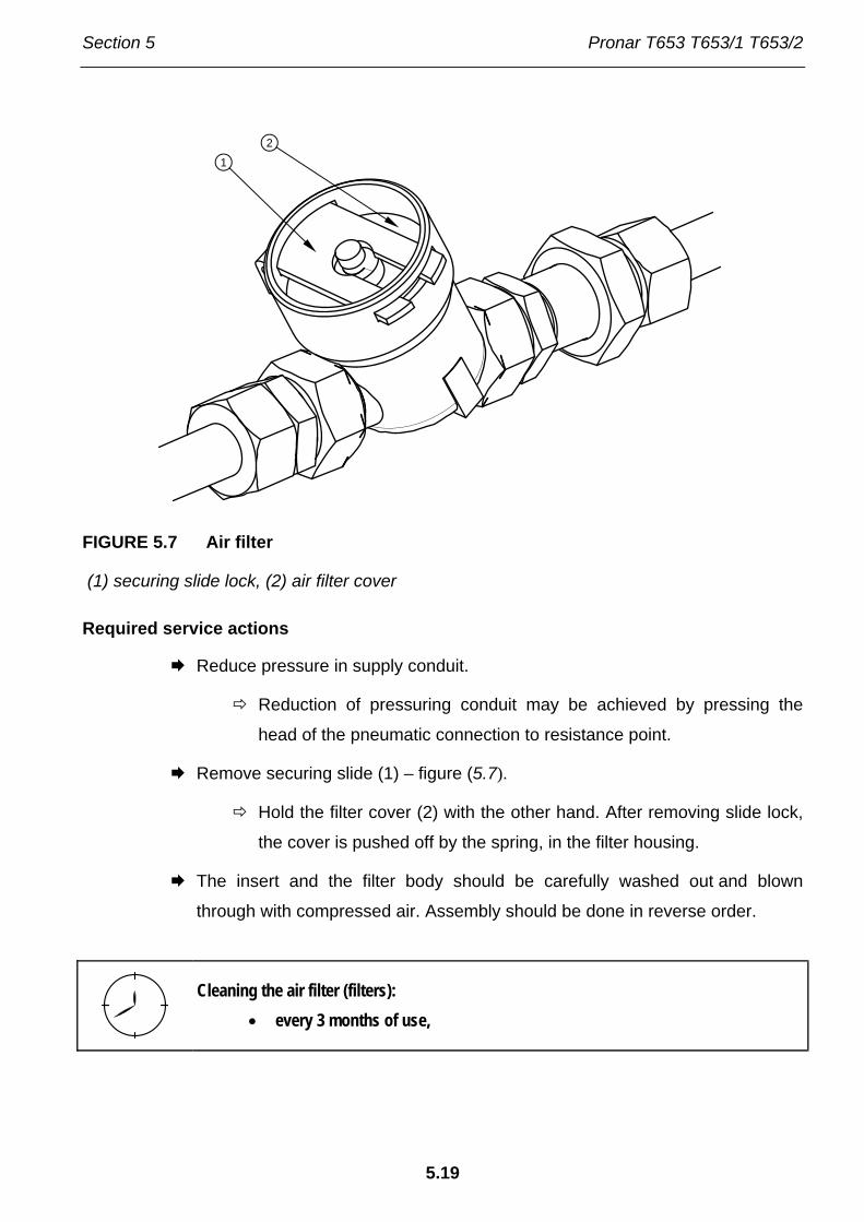
Section 5 Pronar T653 T653/1 T653/2
5.19
FIGURE 5.7 Air filter
(1) securing slide lock, (2) air filter cover
Required service actions
Reduce pressure in supply conduit.
Reduction of pressuring conduit may be achieved by pressing the
head of the pneumatic connection to resistance point.
Remove securing slide (1) – figure (5.7).
Hold the filter cover (2) with the other hand. After removing slide lock,
the cover is pushed off by the spring, in the filter housing.
The insert and the filter body should be carefully washed out and blown
through with compressed air. Assembly should be done in reverse order.
Cleaning the air filter (filters): • every 3 months of use,
1
2

Pronar T653 T653/1 T653/2 Section 5
5.20
5.3.4 DRAINING WATER FROM AIR TANK
FIGURE 5.8 Draining water from air tank
(1) drain valve, (2) air tank,
Required service actions
Open drain valve (1) placed in lower part of tank (2) - tank is placed in rear
part of turntable frame
The compressed air in the tank causes the removal of water to the
exterior.
After release valve pin should automatically close and stop airflow from tank.
In the event, that the valve pin resists returning to its setting, then the
whole drain valve must be unscrewed and cleaned, or replaced (if it is
damaged) - see section 5.3.5.
Draining water from air tank: • every seven days of use.
12

Section 5 Pronar T653 T653/1 T653/2
5.21
5.3.5 CLEANING DRAIN VALVE
DANGER
Before dismantling drain valve release air from tank.
Required service actions
Reduce pressure in air tank.
Reduction of pressure in tank is achieved by tilting the drain valve
mandrel.
Unscrew valve.
Clean valve, purge with compressed air.
Change copper seal.
Screw in valve, fill air tank, and check tank tightness.
Cleaning valve: • every 12 months (before winter period).
5.3.6 CLEANING AND MAINTAINING PNEUMATIC CONDUIT CONNECTIONS AND PNEUMATIC SOCKETS,
DANGER
Unreliable and dirty trailer connections may cause unreliability and faulty functioning of braking system.
Damaged connection body or connection socket to second trailer should be replaced. In
event of damage to cover or seal, change these elements for new reliable elements. Contact
of pneumatic connector seals with oils, grease, petrol etc. may cause damage and accelerate
ageing process.

Pronar T653 T653/1 T653/2 Section 5
5.22
If the trailer is unhitched from the tractor, contact should be protected by cover or placed in its
designated socket. Before the winter period it is recommended to preserve the seal with
special preparations (e.g. silicon grease for rubber elements).
Each time before connection of the machine inspect technical condition and cleanness of
contacts and sockets in tractor. If necessary clean or repair tractor socket.
Inspect trailer connections: • connection should be inspected every time before connecting trailer to
tractor or second trailer.
5.4 HYDRAULIC SYSTEM OPERATION
5.4.1 PRELIMINARY INFORMATION
Work connected with the repair, change or regeneration of hydraulic system components
(tipping cylinder, valves etc.) should be entrusted to specialist establishments, having the
appropriate technology and qualifications for this type of work.
The duties of the operator connected with the hydraulic system include:
• inspecting and checking air tightness of pneumatic system.
• Checking technical conditions of hydraulic connections.
DANGER
Do NOT tip trailer with unreliable hydraulic tipping system. Do NOT use the trailer if hydraulic brake system is unreliable.
5.4.2 CHECKING HYDRAULIC SYSTEM TIGHTNESS
Required service actions
Hitch trailer to tractor.
Connect all hydraulic system conduits according to service instructions.

Section 5 Pronar T653 T653/1 T653/2
5.23
Clean connections and cylinders (tipping cylinder and possibly hydraulic brake
cylinders).
Conduct test tipping of load box sideways and backwards.
Press tractor brake pedal several times
If trailer is equipped with hydraulic brake system.
Check tightness of hydraulic system, inspect cylinders and hydraulic conduits.
In the event of confirmation of oil on hydraulic ram cylinder bodies ascertain origin of leak.
Inspect hydraulic seals when ram cylinder is completely extended. Minimum leaks are
permissible with symptoms of "sweating", however in the event of noticing leaks in the form
of "droplets" stop using the trailer until faults are remedied. If unreliability is evident in brake
cylinders do NOT use trailer with damaged system until faults are remedied.
Checking tightness: • After a week of use
• every 12 months of use.
5.4.3 CHECKING TECHNICAL CONDITION OF HYDRAULIC CONNECTIONS AND SOCKETS.
Hydraulic connections and sockets designed for connection with second trailer must be in
good working condition and kept clean. Each time before connecting check if socket in tractor
or connection of second trailer are maintained in good working condition. Tractor and trailer
hydraulic systems are sensitive to the presence of permanent contamination, which may
cause damage to precision system components (contamination may cause scratching of
hydraulic valves, abrasion of piston surfaces etc.)
Inspection of hydraulic connections and sockets: • connection should be inspected every time before connecting trailer to
tractor or second trailer.

Pronar T653 T653/1 T653/2 Section 5
5.24
5.4.4 CHANGE OF HYDRAULIC CONDUITS
Hydraulic conduits must be changed every 4 years regardless of their technical condition.
This should be entrusted to specialised workshops.
Change of hydraulic conduits: • every 4 years,
5.5 OPERATION OF ELECTRICAL SYSTEM AND WARNING ELEMENTS
5.5.1 PRELIMINARY INFORMATION
Work connected with the repair, change or regeneration of electrical system components
should be entrusted to specialist establishments, having the appropriate technology and
qualifications for this type of work.
The duties of the user are limited to:
• technical inspection of electrical and reflective light system,
• Changing bulbs
IMPORTANT!
Do NOT travel with unreliable lighting system. Damaged lamp lenses, and burned-out bulbs must be replaced immediately before travelling. Lost or damaged reflective lights must be replaced.
Required service actions
Hitch trailer to tractor with appropriate connection lead.
Check if the connection lead is reliable. Check connection sockets in
tractor and trailer.
Check completeness and technical condition of trailer lights.
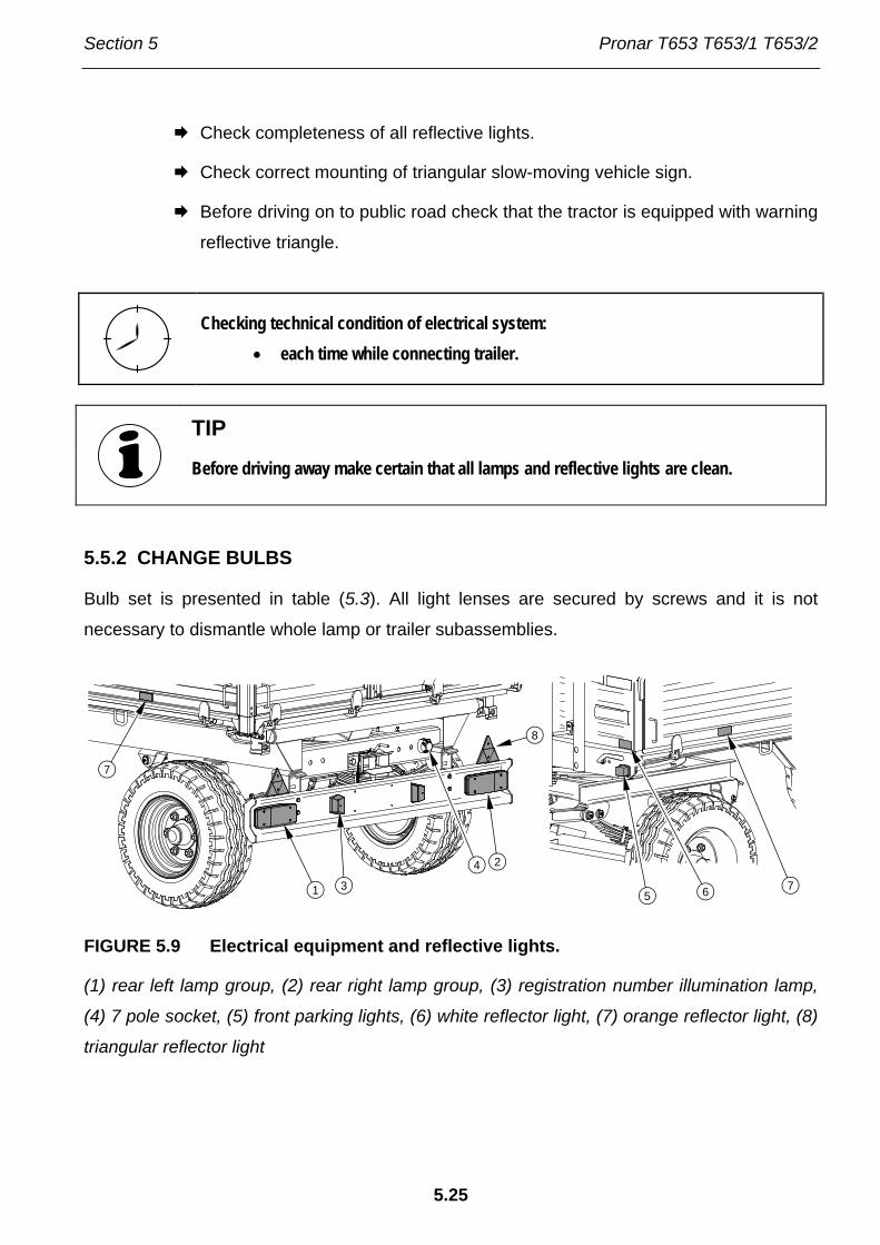
Section 5 Pronar T653 T653/1 T653/2
5.25
Check completeness of all reflective lights.
Check correct mounting of triangular slow-moving vehicle sign.
Before driving on to public road check that the tractor is equipped with warning
reflective triangle.
Checking technical condition of electrical system: • each time while connecting trailer.
TIP
Before driving away make certain that all lamps and reflective lights are clean.
5.5.2 CHANGE BULBS
Bulb set is presented in table (5.3). All light lenses are secured by screws and it is not
necessary to dismantle whole lamp or trailer subassemblies.
FIGURE 5.9 Electrical equipment and reflective lights.
(1) rear left lamp group, (2) rear right lamp group, (3) registration number illumination lamp,
(4) 7 pole socket, (5) front parking lights, (6) white reflector light, (7) orange reflector light, (8)
triangular reflector light
7
8
1
2
3
4
5 6
7
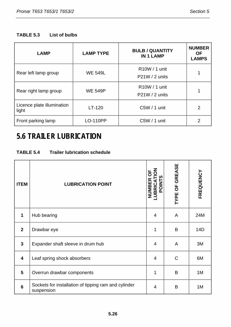
Pronar T653 T653/1 T653/2 Section 5
5.26
TABLE 5.3 List of bulbs
LAMP LAMP TYPE BULB / QUANTITY IN 1 LAMP
NUMBER OF
LAMPS
Rear left lamp group WE 549L R10W / 1 unit P21W / 2 units
1
Rear right lamp group WE 549P R10W / 1 unit P21W / 2 units
1
Licence plate illumination light LT-120 C5W / 1 unit 2
Front parking lamp LO-110PP C5W / 1 unit 2
5.6 TRAILER LUBRICATION
TABLE 5.4 Trailer lubrication schedule
ITEM LUBRICATION POINT
NU
MB
ER O
F LU
BR
ICA
TIO
N
POIN
TS
TYPE
OF
GR
EASE
FREQ
UEN
CY
1 Hub bearing 4 A 24M
2 Drawbar eye 1 B 14D
3 Expander shaft sleeve in drum hub 4 A 3M
4 Leaf spring shock absorbers 4 C 6M
5 Overrun drawbar components 1 B 1M
6 Sockets for installation of tipping ram and cylinder suspension
4 B 1M

Section 5 Pronar T653 T653/1 T653/2
5.27
ITEM LUBRICATION POINT
NU
MB
ER O
F LU
BR
ICA
TIO
N
POIN
TS
TYPE
OF
GR
EASE
FREQ
UEN
CY
7 Tipping ram cylinder ball bearing 1 B 3M
8 Parking brake mechanism 1 A 6M
9 Parking brake guide roller pins (1) 1 A 6M
10 Leaf spring absorber sliding surfaces 4 A 3M
11 Absorber spring pins 4 A 3M
12 Drawbar pins 2 A 3M
13 Turntable 2 A 24M
14 Articulated joints and sockets for installation of load box.
4 B 2M
15 Side extension lug 10 A 1M
16 Linking cable release mechanism lever pin 4 D 6M
17 Slide gate guides 2 D 1M
18 Slide gate pull shaft pins 6 D 1M
19 Wall pins and locks 8 A 1M
Greasing periods – M months, D – days
(1) – not shown in figure
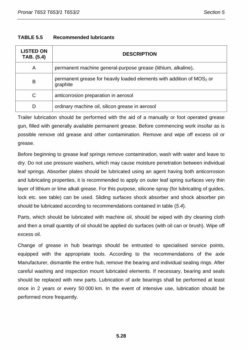
Pronar T653 T653/1 T653/2 Section 5
5.28
TABLE 5.5 Recommended lubricants
LISTED ON TAB. (5.4) DESCRIPTION
A permanent machine general-purpose grease (lithium, alkaline),
B permanent grease for heavily loaded elements with addition of MOS2 or graphite
C anticorrosion preparation in aerosol
D ordinary machine oil, silicon grease in aerosol
Trailer lubrication should be performed with the aid of a manually or foot operated grease
gun, filled with generally available permanent grease. Before commencing work insofar as is
possible remove old grease and other contamination. Remove and wipe off excess oil or
grease.
Before beginning to grease leaf springs remove contamination, wash with water and leave to
dry. Do not use pressure washers, which may cause moisture penetration between individual
leaf springs. Absorber plates should be lubricated using an agent having both anticorrosion
and lubricating properties, it is recommended to apply on outer leaf spring surfaces very thin
layer of lithium or lime alkali grease. For this purpose, silicone spray (for lubricating of guides,
lock etc. see table) can be used. Sliding surfaces shock absorber and shock absorber pin
should be lubricated according to recommendations contained in table (5.4).
Parts, which should be lubricated with machine oil, should be wiped with dry cleaning cloth
and then a small quantity of oil should be applied do surfaces (with oil can or brush). Wipe off
excess oil.
Change of grease in hub bearings should be entrusted to specialised service points,
equipped with the appropriate tools. According to the recommendations of the axle
Manufacturer, dismantle the entire hub, remove the bearing and individual sealing rings. After
careful washing and inspection mount lubricated elements. If necessary, bearing and seals
should be replaced with new parts. Lubrication of axle bearings shall be performed at least
once in 2 years or every 50 000 km. In the event of intensive use, lubrication should be
performed more frequently.

Section 5 Pronar T653 T653/1 T653/2
5.29
FIGURE 5.10 Trailer's lubrication points, part 1
1M1M
1M
3M
6M
24M
1M
2M
6M
3M
2M
24M
14D
1
2
68
12
13
14
15
16
7
19
14
1M5

Pronar T653 T653/1 T653/2 Section 5
5.30
FIGURE 5.11 Trailer's lubrication points, part 2
3M
1M
3M
6M3M
18 18
1717
18
10
11
34

Section 5 Pronar T653 T653/1 T653/2
5.31
Empty grease or oil containers should be disposed of according to the recommendations of
the lubricant Manufacturer.
During trailer use the user is obliged to observe lubrication instructions according to attached lubrication schedule.
5.7 CONSUMABLES
5.7.1 HYDRAULIC OIL
Always adhere to the principle that the oil in the trailer hydraulic system and in the tractor
hydraulic system are the same type. In the event of application of different types of oil make
certain that both hydraulic substances may be mixed together. Application of different oil
types may cause damage to trailer or tractor. In a new machine system is filled with L HL32
Lotos hydraulic oil.
TABLE 5.6 L-HL 32 Lotos hydraulic oil characteristics
ITEM NAME UNIT VALUE
1 ISO 3448VG viscosity classification - 32
2 Kinematic viscosity at 40°C mm2/s 28.8 – 35.2
3 ISO 6743/99 quality classification - HL
4 DIN 51502 quality classification - HL
5 Ignition temperature C 230
In the event of necessity of changing hydraulic oil for another oil, check the recommendations
of the oil manufacturer very carefully. If it is recommended to flush the system with the
appropriate preparation, then comply with these recommendations. Attention should be
given, so that chemical substances used for this purpose do not damage the materials of the
hydraulic system. During normal trailer use change of hydraulic oil is not necessary, but if
required, this operation should be entrusted to a specialist service point.
The oil applied because of its composition is not classified as a dangerous substance,
however long-term action on the skin or eyes may cause irritation. In the event of contact of

Pronar T653 T653/1 T653/2 Section 5
5.32
oil with skin wash the place of contact with water and soap. Do not apply organic solvents
(petrol, kerosene). Contaminated clothing should be changed to prevent access of oil to skin.
In the event of contact of oil with eye, rinse with large quantity of water and in the event of the
occurrence of irritation consultant a doctor. Hydraulic oil in normal conditions is not harmful to
the respiratory tract. A hazard only occurs when oil is strongly atomised (oil vapour), or in the
case of fire during which toxic compounds may be released. Oil fires should be quenched
with the use of carbon dioxide, foam or extinguisher steam. Do not use water to quench oil
fires.
5.7.2 RECOMMENDED GREASE
For parts under great load it is recommended to apply lithium grease with molybdenum
disulphide (MOS2) or graphite additive. In the case of less loaded sub-assemblies the
application of general purpose machine greases is recommended, which contain
anticorrosion additive and are resistant to being washed away by water to a considerable
degree. Similar characteristics should typify aerosol preparations (Silicon greases and
anticorrosive lubricant substances).
Before starting to use greases acquaint oneself with the content off the information leaflet for
the chosen product. Particularly relevant are safety rules and handling procedures for given
lubricant product and waste utilisation (used containers, contaminated rags etc). Information
leaflet (material safety data sheet) should be kept together with grease.
5.8 CLEANING TRAILER
Trailer should be clean depending on requirements and before longer idle periods (e.g.
before winter period). Before using pressure washer the user is obliged to acquaint himself
with the operating principles and recommendations concerning safe use of this equipment.
Trailer cleaning guidelines
• Before washing trailer open all sides and extensions. Carefully clean load remains
from the load box (sweep out or blow out with compressed air), especially where
sides and extensions join and.
• To clean trailer only use clean running water or water with a cleaning detergent
additive with neutral pH.

Section 5 Pronar T653 T653/1 T653/2
5.33
• Using pressure washer increases washing effectiveness, but particular care must
be taken during work. During washing washer nozzle may not be closer than 50
cm from the surface being cleaned.
• Water temperature shall not exceed 55°C.
• Do not direct water stream directly at system and equipment elements of trailer
i.e. control valve, braking force regulator, brake cylinders, hydraulic cylinders,
pneumatic, electric and hydraulic plugs, lights, electrical connections, information
and warning decals, identification plates, conduit connections, leaf springs and
trailer lubrication points etc. Great water jet pressure may damage these
elements.
• For cleaning and maintenance of plastic coated surface it is recommended to use
clean water or special preparations designed for this purpose.
• Do not apply organic solvents, preparations of unknown origin or other
substances, which may cause damage to lacquered, rubber or plastic surfaces. In
the event of doubt it is recommended to make a test on an unseen surface area.
• Surfaces smeared with oil or grease should be cleaned by application of benzene
or other degreasing agents and then washed with clean water with added
detergent. Comply with recommendations of the Manufacturer.
DANGER
Carefully read the instructions for application of washing detergents and maintenance preparations. While washing with detergents wear appropriate protective clothing and goggles protecting against splashing.
• Washing detergent should be kept in original containers, optionally in replacement
containers, but very clearly marked. Preparations may not be stored in food and
drink containers.
• Care for the cleanness of elastic conduits and seals. The plastic from which these
elements are made may be susceptible to organic substances and some
detergents. As a result of long-term reaction of some substances, the ageing
process may be accelerated and risk of damage increased. Rubber elements

Pronar T653 T653/1 T653/2 Section 5
5.34
should be maintained with the aid of special preparations after previous thorough
washing.
• After finishing washing wait until trailer is dry and then grease all inspection points
according to recommendations. Remove excess oil or grease with a dry cloth.
• Observe environmental protection principles and wash trailer in a place
designated for such purpose.
• Washing and drying trailer must take place at temperatures above 0°C.
• After washing and drying trailer should be greased at all control points regardless
of last lubrication period.
5.9 STORAGE
• Trailer should be kept in closed or roofed building.
• If the machine will not be used for a long time, it is essential to protect it from
adverse weather, especially rust and accelerated tyre deterioration. During this
time trailer must be unloaded. Trailer should be very carefully washed and dried.
• Corroded places should be cleaned of rust, degreased and protected using
undercoat paint and then painted with surface paint according to colour scheme.
• In the event of prolonged work stoppage, it is essential to lubricate all elements
regardless of the period of the last lubrication process.
• Wheel rims and tyres should be carefully washed and dried. During longer
storage of unused trailer it is recommended that every 2 to 3 weeks the machine
may be moved a bit so that the place of contact of tyres with ground is changed.
So that tyres are not deformed and maintain proper geometry. Also tyre pressure
should be inspected from time to time, and if necessary pressure should be
increased to appropriate value.
• If trailer is equipped with tarpaulin it should be carefully washed and dried. If
possible clean tarpaulin should be stored unrolled, otherwise carefully roll it not
causing crushing and breaking of material.

Section 5 Pronar T653 T653/1 T653/2
5.35
5.10 TIGHTENING TORQUE FOR NUT AND BOLT CONNECTIONS
Unless other tightening parameters are given, during maintenance repair work apply
appropriate torque to tightening nut and bolt connections. Recommended tightening torque of
most frequently applied nut and bolt connections are given in table below. Given values apply
to non greased steel bolts.
TABLE 5.7 Tightening torque for nut and bolt connections
5.8(1) 8.8(1) 10.9(1) THREAD METRIC Md [Nm]
M10 37 49 72
M12 64 85 125
M14 100 135 200
M16 160 210 310
M20 300 425 610
M24 530 730 1 050
M27 820 1 150 1 650
M30 1 050 1 450 2 100
(1) – resistance class according to DIN ISO 898 standard
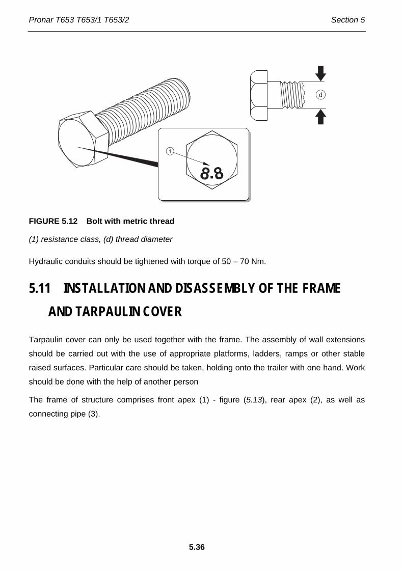
Pronar T653 T653/1 T653/2 Section 5
5.36
FIGURE 5.12 Bolt with metric thread
(1) resistance class, (d) thread diameter
Hydraulic conduits should be tightened with torque of 50 – 70 Nm.
5.11 INSTALLATION AND DISASSEMBLY OF THE FRAME AND TARPAULIN COVER
Tarpaulin cover can only be used together with the frame. The assembly of wall extensions
should be carried out with the use of appropriate platforms, ladders, ramps or other stable
raised surfaces. Particular care should be taken, holding onto the trailer with one hand. Work
should be done with the help of another person
The frame of structure comprises front apex (1) - figure (5.13), rear apex (2), as well as
connecting pipe (3).
d
1
8.8
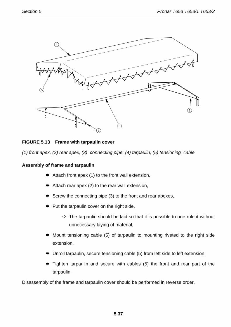
Section 5 Pronar T653 T653/1 T653/2
5.37
FIGURE 5.13 Frame with tarpaulin cover
(1) front apex, (2) rear apex, (3) connecting pipe, (4) tarpaulin, (5) tensioning cable
Assembly of frame and tarpaulin
Attach front apex (1) to the front wall extension,
Attach rear apex (2) to the rear wall extension,
Screw the connecting pipe (3) to the front and rear apexes,
Put the tarpaulin cover on the right side,
The tarpaulin should be laid so that it is possible to one role it without
unnecessary laying of material,
Mount tensioning cable (5) of tarpaulin to mounting riveted to the right side
extension,
Unroll tarpaulin, secure tensioning cable (5) from left side to left extension,
Tighten tarpaulin and secure with cables (5) the front and rear part of the
tarpaulin.
Disassembly of the frame and tarpaulin cover should be performed in reverse order.
1
2
3
4
5

Pronar T653 T653/1 T653/2 Section 5
5.38
DANGER
Assembly and disassembly of the frame should be carried out with the use of appropriate platforms, ladders or when standing on a ramp. These tools must be in good condition to fully protect the persons working on them against falling. Work should be performed by at least two persons. Exercise caution when working.
5.12 INSTALLATION AND DISASSEMBLY OF EXTENSION WALLS
DANGER
Assembly and disassembly of wall extensions should be carried out with the use of appropriate platforms, ladders or when standing on a ramp. These tools must be in good condition to fully protect the persons working on them against falling. Work should be performed by at least two persons. Exercise caution when working.
Extension mounting
Secure rear extension stakes to rear side stakes.
Install front wall extension.
Install rear wall extension.
Install side wall extensions.
First place upper pins of extension in appropriate rear stake locks and
front walls, and after that secure base of extensions with the aid of pin
lugs to upper part of side walls.
Screw in extension ladder to the front wall.
Disassembly of wall extensions should be performed in reverse order.

Section 5 Pronar T653 T653/1 T653/2
5.39
5.13 ADJUSTMENT OF DRAWBAR POSITION
FIGURE 5.14 Adjustment of drawbar position
(1) tension spring, (2) tensioner
Adjustment of drawbar position is achieved by changing the links of the tensioning bolt
(2) - (internally threaded sleeve nut) The spring tension (1) is not changed by this operation.
The spring is designed solely for maintaining the set drawbar height. In many upper transport
hitch solutions of tractors it is possible to adjust its height to the hitch of the machine.
Therefore it is recommended to adjust the drawbar and the tractor hitching in such a way, so
that the drawbar would be set in the horizontal position or with a slight incline upwards toward
the tractor.
5.14 TROUBLESHOOTING
TABLE 5.8 Troubleshooting
FAULT CAUSE REMEDY
Brake system pneumatic conduits not connected
Connect brake conduits (applies to pneumatic systems) Problem with moving off
Applied parking brake Release parking brake.
12

Pronar T653 T653/1 T653/2 Section 5
5.40
FAULT CAUSE REMEDY
Damaged pneumatic system connection conduits Replace.
Leaking connections Tighten, replace washers or seal set, replace conduits.
Damage control valve or brake force regulator Check valve, repair or replace.
Excessive slack in bearings Check slack and regulate if needed
Damaged bearing Replace bearing Noise in axle hubs
Damaged hub parts Replace
Poor reliability of braking system
Insufficient pressure in system
Check pressure on tractor pressure gauge, wait till compressor fills tank to required pressure. Damaged air compressor in tractor Repair or replace. Damaged brake valve in tractor. Repair or replace. Leaking system conduits or connections. Check system for tightness.
Incorrect main or parking brake adjustment Regulate setting of expander armsExcessive heating of axle
hubs Worn brake linings Change brake shoes
Improper hydraulic oil viscosity
Check oil quality, make sure that the oil in both machines is at the same type. If necessary change oil in tractor or in trailer
Incorrect hydraulic system operation
Insufficient tractor hydraulic pump output, tractor hydraulic pump is damaged.
Check tractor hydraulic pump.

Section 5 Pronar T653 T653/1 T653/2
5.41
FAULT CAUSE REMEDY
Damaged or contaminated ram cylinder
Check cylinder ram piston (bending, corrosion), check ram cylinder for tightness (piston seal), in case of need repair or replace ram cylinder.
Excessive cylinder ram loading
Check mechanism controlled by ram cylinder for mechanical damage
Damaged hydraulic conduits
Check and ascertain that hydraulic conduits are tight, not fractured and properly tightened. If necessary replace or tighten.

Pronar T653 T653/1 T653/2 Section 5
5.42

NOTES
……………………………………………………………………………………………………………
……………………………………………………………………………………………………………
……………………………………………………………………………………………………………
……………………………………………………………………………………………………………
……………………………………………………………………………………………………………
……………………………………………………………………………………………………………
……………………………………………………………………………………………………………
……………………………………………………………………………………………………………
……………………………………………………………………………………………………………
……………………………………………………………………………………………………………
……………………………………………………………………………………………………………
……………………………………………………………………………………………………………
……………………………………………………………………………………………………………
……………………………………………………………………………………………………………
……………………………………………………………………………………………………………
……………………………………………………………………………………………………………
……………………………………………………………………………………………………………
……………………………………………………………………………………………………………
……………………………………………………………………………………………………………
……………………………………………………………………………………………………………
……………………………………………………………………………………………………………
……………………………………………………………………………………………………………
……………………………………………………………………………………………………………
……………………………………………………………………………………………………………

……………………………………………………………………………………………………………
……………………………………………………………………………………………………………
……………………………………………………………………………………………………………
……………………………………………………………………………………………………………
……………………………………………………………………………………………………………
……………………………………………………………………………………………………………
……………………………………………………………………………………………………………
……………………………………………………………………………………………………………
……………………………………………………………………………………………………………
……………………………………………………………………………………………………………
……………………………………………………………………………………………………………
……………………………………………………………………………………………………………
……………………………………………………………………………………………………………
……………………………………………………………………………………………………………
……………………………………………………………………………………………………………
……………………………………………………………………………………………………………
……………………………………………………………………………………………………………
……………………………………………………………………………………………………………
……………………………………………………………………………………………………………
……………………………………………………………………………………………………………
……………………………………………………………………………………………………………
……………………………………………………………………………………………………………
……………………………………………………………………………………………………………
……………………………………………………………………………………………………………
……………………………………………………………………………………………………………
……………………………………………………………………………………………………………
……………………………………………………………………………………………………………

ANNEX A
Tyre dimensions
TRAILER VERSION AXLE FRONT / REAR
T653 10.0/75-15.3 122 A8 (1)
T653/1 11.5/80-15.3 130 A8 (1)
14.0/65-16 134 A8 (2)
T653/2 11.5/80-15.3 134 A8 (1)
14.0/65-16 134 A8 (2)
T653/2 WITH OVERRUN BRAKE 11.5/80-15.3 134 A8 (1)
14.0/65-16 134 A8 (2)
(1) - wheel disc 9.00x15.3"
(2) - wheel disc 11x16" ET=-20