Embed Size (px)
Citation preview

-AD-AlES 765 LAES FIELD AZORES POL PIER FIELD INVESTIGATIONS AND 1.02RECONNENDATIONS(U) NAVAL FACILITIES ENGINEERING CONNANDMASNIOTON DC CHESAPEAKE.. C CHERN ET AL. NAR ?6
UNCLASSIFIED CHES/NRYFAC-FPO-1-?8C6) F/0 13/2 UL
mhEEEEmohmhhhEI
I fflfflf..ffl~lfMEf

1.0~ ~ ~ ~ 1 '121L
U2 112.
36(j2/
M ICROCOPY PR '' f Iii N ffST CHAT
.t-j-. - r-y --~ -. -- - --------- - -
FPO-2 FPO7806
*D\1 DTlCELE.CTEDMAR 19
IV
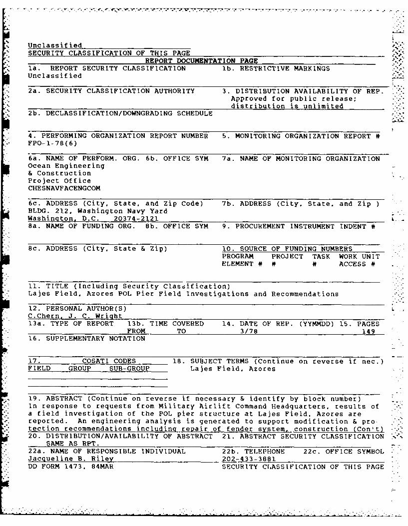
LAJES FIELD, AZORESP01 PIERFIELD INVESTIGATIONS ANDRECOMMENDATIONSr " BON 1 8TAfE~ffJjr A
CmmLi AAWOYed fGI Pubhoj ej0 q__jDistzibuti11 Uklirzljso
FPO- 1-78 (6)MARCH 1978 a
Ref. .
150
EAN ENGINEERING AND CONSTRUCTION PROJECT OFFICE:SAPEAKE DIVISIONV/AL FACILITIES ENGINEERING COMMAND
V:ASHINGTON, D. C. 203740b -7 ' * 0 0
.''
UnclassifiedSECURITY CLASSIFICATION OF THIS PAGE
REPORT DOCUMENTATION PAGEla. REPORT SECURITY CLASSIFICATION lb. RESTRICTIVE MARKINGSUnclassified
2a. SECURITY CLASSIFICATION AUTHORITY 3. DISTRIBUTION AVAILABILITY OF REP.Approved for public release;distribution is unlimited
2b. DECLASSIFICATION/DOWNGRADING SCHEDULE
4. PERFORMING ORGANIZATION REPORT NUMBER 5. MONITORING ORGANIZATION REPORT 4FPO-I-78(6)
6a. NAME OF PERFORM. ORG. 6b. OFFICE SYM 7a. NAME OF MONITORING ORGANIZATIONOcean Engineering& ConstructionProject OfficeCHESNAVFACENGCOM
6c. ADDRESS (City. State. and Zip Code) 7b. ADDRESS (City. State. and Zip )BLDG. 212. Washington Navy YardWashington, D.C. 20374-2121Ba. NAME OF FUNDING ORG. 8b. OFFICE SYM 9. PROCUREMENT INSTRUMENT INDENT 4
8c. ADDRESS (City. State & Zip) 10. SOURCE OF FUNDING NUMBERSPROGRAM PROJECT TASK WORK UNITELEMENT # ## ACCESS #
11. TITLE (Including Security Classification)Lajes Field, Azores POL Pier Field Investigations and Recommendations
12. PERSONAL AUTHOR(S)C.Chern, J. C. Wright13a. TYPE OF REPORT 13b. TIME COVERED 14. DATE OF REP. (YYMMDD) 15. PAGES
FROM TO 3/78 14916. SUPPLEMENTARY NOTATION
17. COSATI CODES 18. SUBJECT TERMS (Continue on reverse if nec.)FIELD GROUP SUB-GROUP Lajes Field, Azores
19. ABSTRACT (Continue on reverse if necessary & identify by block number)In response to requests from Military Airlift Command Headquarters, results ofa field investigation of the POL pier structure at Lajes Field. Azores arereported. An engineering analysis is generated to support modification & pro-tection recommendations including repair of fender system, construction (Con't)20. DISTRIBUTION/AVAILABILITY OF ABSTRACT 21. ABSTRACT SECURITY CLASSIFICATION
SAME AS RPT.22a. NAME OF RESPONSIBLE INDIVIDUAL 22b. TELEPHONE 22c. OFFICE SYMBOLJacgueline B. Riley 202-433-3881DD FORM 1473. 84MAR SECURITY CLASSIFICATION OF THIS PAGE
-o/' ",I OF v
DEPARTMENT OF THE NAVY "
CHESAPEAKE DIVISION
NAVAL FACILITIES ENGINEERING COMMAND
BUILDING 57, WASHINGTON NAVY YARD
WASHINGTON, D.C. 20374 IN REPLV REFER TO.
* FPO-.lIP:cgw.
r~~ -4F. "-CF.
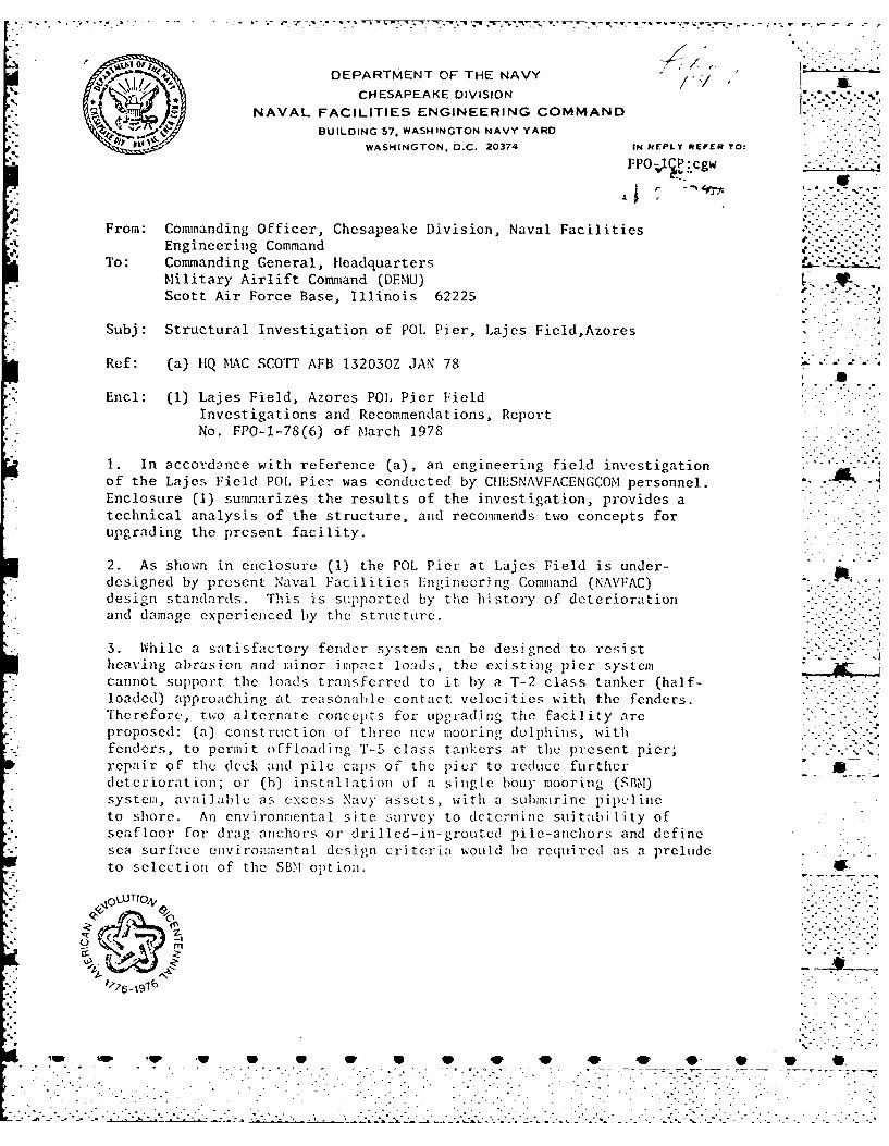
From: Commanding Officer, Chesapeake Division, Naval FacilitiesEngineering Command
To: Commanding General, HeadquartersMilitary Airlift Command (DEMU)Scott Air Force Base, Illinois 62225
Subj: Structural Investigation of POL Pier, Lajes Field,Azores
Ref: (a) 11Q MAC SCOTT AFB 132030Z JAN 78
End: (1) Lajes Field, Azores POL Pier FieldInvestigations and Recommendations, ReportNo. FPO-1-78(6) of March 1978
1. In accordance with reference (a), an engineering field investigationof the Lajes Field PO[, Pier was conducted by CfHESNAVFACENGCOM personnel.Enclosure (1) summarizes the results of the investigation, provides atechnical analysis of the structure, and recommends two concepts forupgrading the present facility.
2. As shown in enclosure (1) the POL Pier at Lajes Field is under-designed by present Naval Facilities Engineering Command (NAVFAC)design standards. This is supported by the history of deteriorationand damage experienced by the structure.
3. While a satisfactory fender system can be designed to resistheaving abrasion and imiinor impact loads, the existing pier systemcannot support the loads transferred to it by a T-2 class tanker (half-loaded) approaching at reasonable contact velocities with the fenders.Therefore, two alternate concepts for uipgrading the facility areproposed: (a) construction of three new mooring dolphins, withfenders, to permit offloading "i"-5 class tankers at the present pier; .. :- " -repair of the deck and pile caps of the pier to reduce furthcr "deterioration; or (b) installation of a single bouy mooring (SBM)system, available as excess Navy' assets, with a submarine pipclincto shore. An environmental site survey to determine suitability ofseafloor for drag anchors or drilled-in-grouted pile-anchors and definesea surface environmental design criteria woould be required as a prelude . ...to selection of the SBM option.
. pUTI-0,
0 0
WW 4W 4F W 1WU ~ 0 0

FPO-lCP:cgw
Subj: Structural Investigation of POL Pier, Lajes Field, Azores
4. Although firm cost estimates are unavailable wi-h thisinvestigation, it appears that even with the basic S9,1 systemavailable as excess, the cost of an installed SBM system would ~.be approximately three times that of the new dolphin and fender Vsystem. Other factors must also be considered such as periodicdredging, harbor pilot fees, and operational commitments forfixed or removable facilities.
5. This command is available to provide further consultation,design, site surveys, or construction support on a reimbursablebasis. Discussion of subsequent efforts or questions may bedirected to LT J1. C. h.right, (Codc FPO-lC-P) at Antovon 288-3881.. -
By d r~ction
Copy to:CERC (Attn: J. Eckert) -1 w/encl21st AF/LG I w/encl160Sth AB;%/CUS(DE) - 3 wfencl
NAVFAC (064) -1 w/enclNAVFAC (PC-2) -w/cncl
CINCLANFFLT (.1413) -w/o encl
2
"P qp 0 0 40 ** W ..

.. . . . .. . . . . . . ..................... ..
. . f o~ . . ob
.* j - . . . . .
-- FPO-1-78-(6)
C. -CHoO.° N
LT. C. W
LAJES FIELD, AZORES
POL PIER COMMANDFIELD INVESTIGATIONS ANDROJECTOFF
RECOMMENDATIONS
C. CHERNU LT J. C. WRIGHT
MARCH 1978
CHESAPEAKE DIVISION- ~~NAVAL FACILITIES ENGINEERING COMMAND ...
" OCEAN ENGINEERING AND CONSTRUCTION PROJECT OFFICE" '("" "" ~WASHINGTON NAVY YARD ((]-: -! UNDER JOB ORDER NO. 946997
. . -; ; --. . - .- . - . . a.t - -.. . .- -. - . . - *.- -; - - T . .. . . ..

ABSTRACT
In response to requests from Military Airlift Command Headquarters, 4
results of a field investigation of the POL pier structure at Lajes Field,Azores are reported. An engineering analysis is generated to supportmodification and protection recommendations including repair of fender............system, construction of additional mooring dolphins, or installation of
a tingle buoy mooring system.
ACA
a
By
Av'S iit oe
C~iaUo
LusLin
~ '* * *~ # SCIF
.. . .r ..~ . . .r .
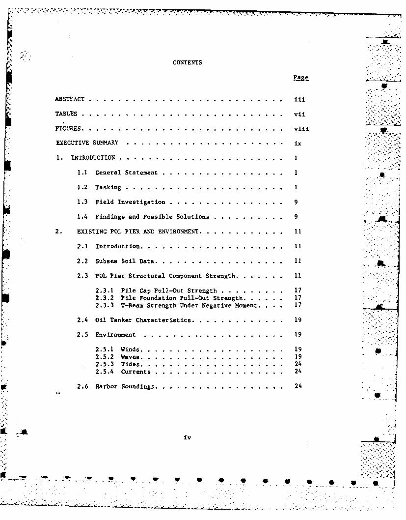
CONTENTS
Paste
ABSTACT .ii .........
*TABLES .. ............................ vii
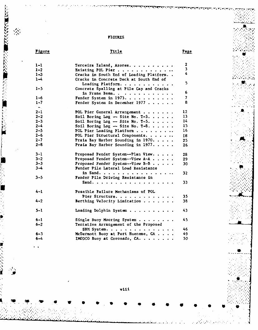
*FIGURES .. .. .. .. .. .. .. .. .. .. .. .. .. . .viii
EXECUTIVE SUMMARY ...................... i
* 1. INTRODUCTION.................. . . ... . . .. .. .. ....
1.1 General Statement....... ...... . . .. .. .. .. ... 1
1.2 Tasking.................. . . .... ... .. .. .. ....
1.3 Field Investigation .. ..... ........... 9
1.4 Findings and Possible Solutions. ........ ... 9
2. EXISTING POL PIER AND ENVIRONMENT .. ........ .... 11
*2.1 Introduction. .. ................... 11
2.2 Subsea Soil Data. .. ................. 11
2.3 POL Pier Structural Component Strength .. .... ... 11
2.3.1 Pile Cap Pull-Out Strength. ........... 172.3.2 Pile Foundation Pull-Out Strength .. ... ... 172.3.3 T-Beam. Strength Under Negative Moment .. . . 17
2.4 Oil Tanker Characteristics .. .......... ... 19
2.5 Environment ........... ............ 19
2.5.1 Winds .. ........ ............ 192.5.2 Waves .. .......... .......... 192.5.3 Tides .. ....... ............. 242.5.4 Currents. ........ ........... 24
3'2.6 Harbor Soundings .. ........... ....... 24
iv
' ~ l '4w l* V P ~ * . .
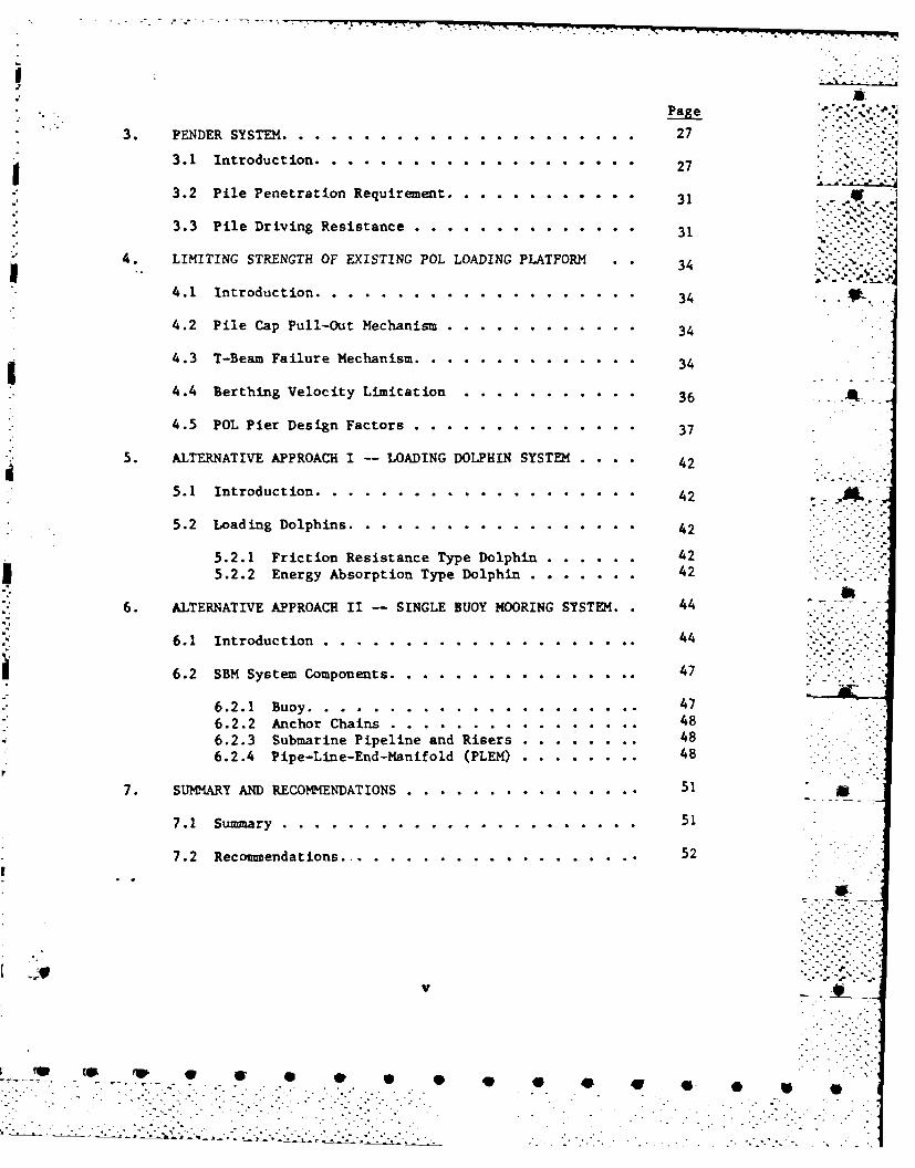
3. FENDER SYSTEM. .. ...................... 27
3.1 introduction............ . .. . .. .. .. .. .... 2 27-i3.2 Pile Penetration Requirement........ .. .. .. ..... 3
3.3 Pile Driving Resistance .. ............... 31
4. LIMITING STRENGTH OF EXISTING POL LOADING PLATFORM .34
4.1 Introduction. .. .................... 34
4.2 Pile Cap Pull-Out Mechanism......... .. .. .. ..... 3
4.3 T-Beam Failure Mechanism..... .. . .. .. .. .. .... 3
4.4 Berthing Velocity Limitation .. ............ 36
4.5 POL Pier Design Factors. .. .............. 37
5. ALTERNATIVE APPROACH I -- LOADING DOLPHIN SYSTEM .... 42
5.1 Introduction. .. .................... 42 i5.2 Loading Dolphins .. .. ................. 42
5.2.1 Friction Resistance Type Dolphin. .. ...... 42
55.2.2 Energy Absorption Type Dolphin. .. ....... 42
6. ALTERNATIVE APPROACH II -- SINGLE BUOY MOORING SYSTEM. 44
6.1 Introduction .. ..................... 44
6.2 SEM System Components .. .. ............... 47
6.2.1 Buoy .. .. .................... 476.2.2 Anchor Chains .. ................ 486.2.3 Submarine Pipeline and Risers. ... ....... 486.2.4 Pipe-Line-End-Manifold (PLEM). .......... 48
7. SUMMARY AND RECOMMENDATIONS. .... ................5
7.1 Summary. .. ...................... 51
7.2 Recomendations ... .. ................ 52
V
__ 0. lip 4 * SL
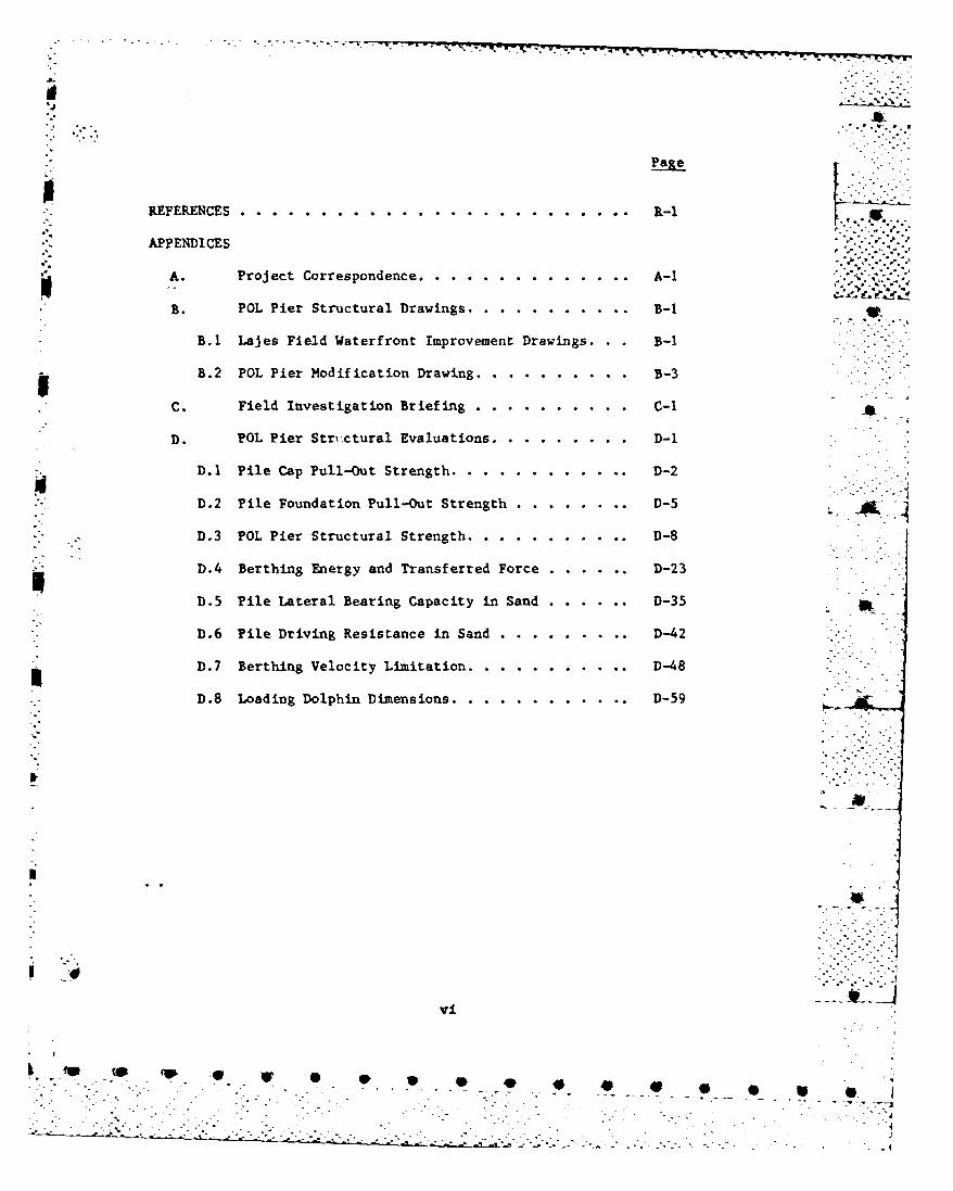
SREFERENCES .. .............. ...........- 1
APPENDICES p-
A. Project Correspondence .. .. ............ A-i
B. POL Pier Structural Drawings.. .. ......... B-1
B.1 Lajes Field Waterfront Improvement Drawings. . B-i
B.2 POL Pier Modification Drawing. .. ........ 3
C. Field Investigation Briefing. .. ......... C-1
D. POL Pier Stri.ctural Evaluations .. .. ....... D-1
D.1 Pile Cap Pull-Out Strength .. .. ...........- 2
D.2 Pile Foundation Pull-Out Strength. .. ........- 5
D.3 POL Pier Structural Strength .. .. ..........-8
D.4 Berthing Energy and Transferred Force. .. ......- 23
D.5 Pile Lateral Bearing Capacity in Sand. .. ......- 35
D.6 Pile Driving Resistance in Sand. .. ........ D-42
D.7 Berthing Velocity Limitation .. .. ......... D-48
-*D.8 Loading Dolphin Dimensions .. .. ...........- 59
IVi
.. 7 -4
TABLES
Table Title Page
2-1 Characteristics of United StatesNavy Oilers. .. .. ............ 20
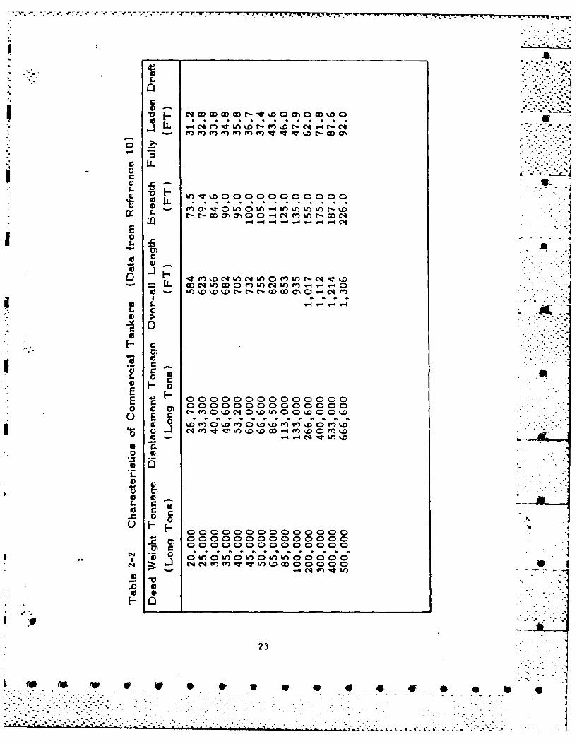
2-2 Characteristics of CommercialTankers ... .. .............. 23
4-1 POL Pier Design Factors. .. .. ....... 39
Vii x
'SW 4p is0V0 4 V
LJ I
FIGURES
FiueTitle Page U
1-1 Terceira Island, Azores. . .. .. .-. .... . . 21-2 Existing POL Pier ..... ............ .. 31-3 Cracks in South End of Loading Platform. 41-4 Cracks in Concrete Deck at South End ofLoading Platform . . ." .- . . . i
1-5 Concrete Spalling at Pile Cap and Cracksin Frame Beam... ......... . 6
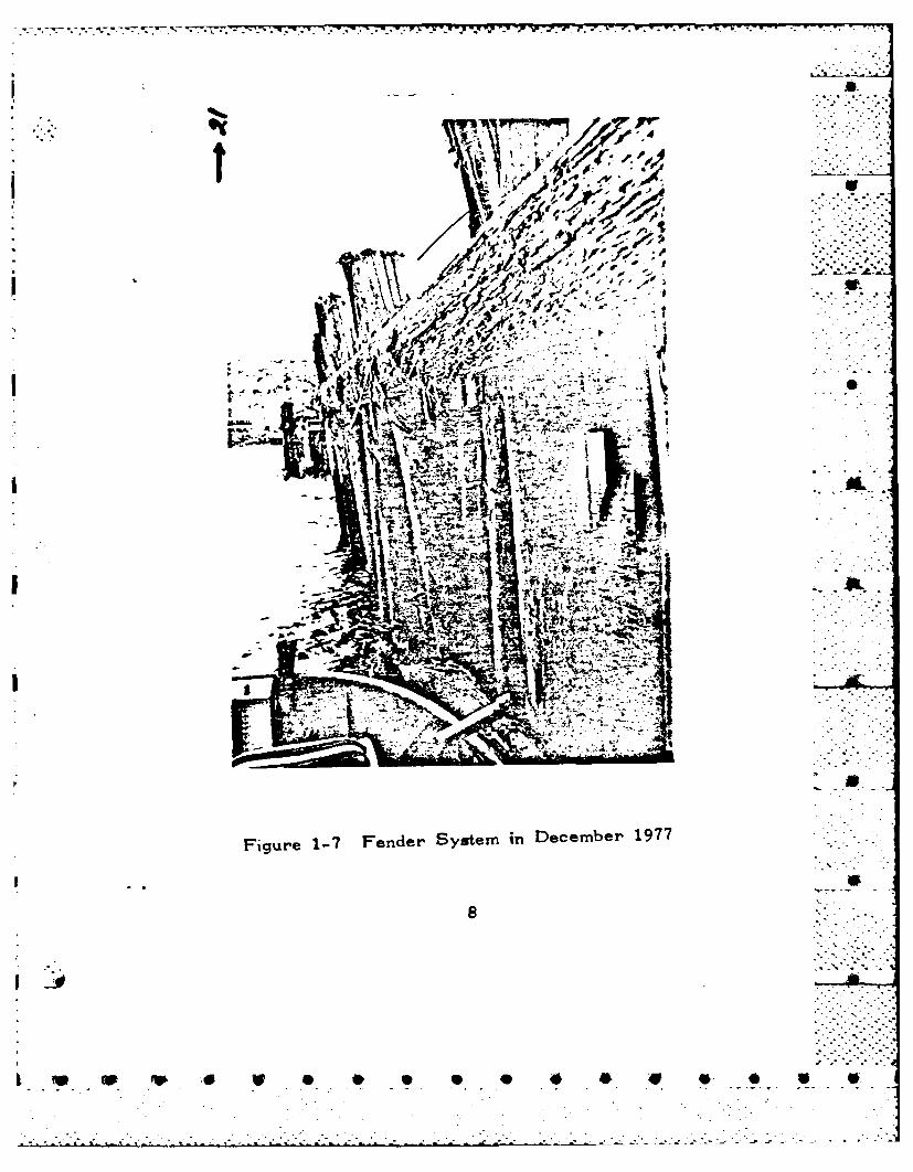
1-6 Fender System in 1973 ................. 7....71-7 Fender System in December 1977 ...... 8
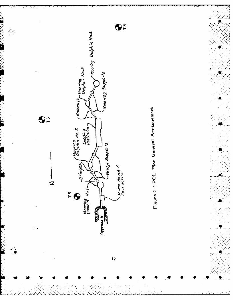
2-1 POL Pier General Arrangement ....... ... 12 W - -2-2 Soil Boring Log - Site No. T-3 .... ... 132-3 Soil Boring Log - Site No. T-5 ...... 14
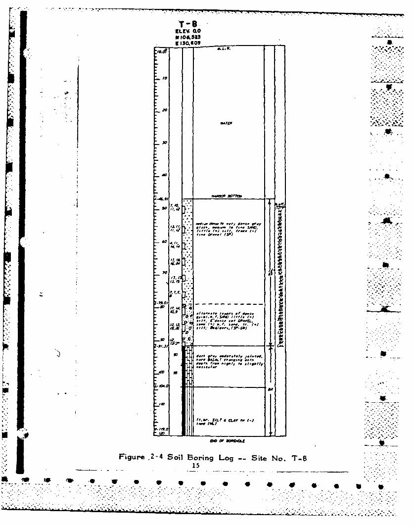
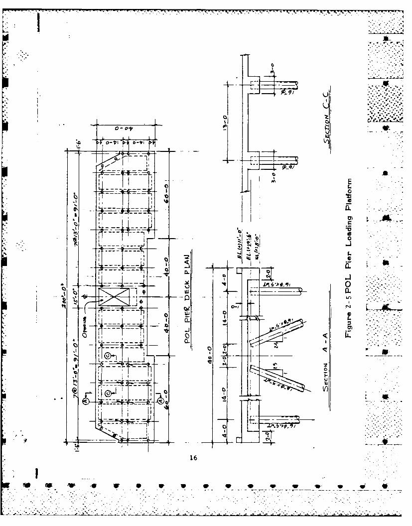
2-4 Soil Boring Log - Site No. T-8 ... ...... 152-5 POL Pier Loading Platform ... ......... 162-6 POL Pier Structural Components .......... 182-7 Praia Bay Harbor Sounding in 1970. . ..... 252-8 Praia Bay Harbor Sounding in 1977 .. .. . .. 26
3-1 Proposed Fender System--Plan View. .. . . . 283-2 Proposed Fender System--View A-A .. ..... 293-3 Proposed Fender System--View B-B .. ..... 303-4 Fender Pile Lateral Load Resistance
in Sand. ................. 323-5 Fender Pile Driving Resistance in
Sand... ..... ............... .. .. 33
4-1 Possible Failure Mechanisms of POLPier Structure. ............ 35
4-2 Berthing Velocity Limitation . . . . . . . 38
5-1 Loading Dolphin System ........... . 43
6-1 Single Buoy Mooring System ............ 456-2 Tentative Arrangement of the Proposed
SBM System .... .............. ... 466-3 McDermott Buoy at Port Hueneme, CA . . .. 496-4 IMODCO Buoy at Coronado, CA .......... ... 50 . -
viii
o ,w° . o .4. '
... ... ... .................. -..L ."' " ".'

EXECUTIVE SUMM..ARY
This report is in response to the tasking of the Military Airlift CommandHeadquarters (MACHQ) for engineering assistance to the Civil Engineering .. 'Squadron (CES) on the POL pier at Lajes Field, Terceira Island, Azores.The task includes:
9 A field investigation of the POL pier structure,
e A technical evaluation and analysis of the existingsituation,
* A report of recommendations for modification of theexisting POL pier structure to accommodate up to40,000 DWT tankers.
LT J.C. Wright and Dr. C. Chern of the Ocean Engineering and Construction
Project Office (CODE FPO-1), Chesapeake Division, Naval Facilities Engi-neering Command (CRESNAVFACENGCOM), carried out the field investigation
between 31 January to 3 February 1978. A briefing of the results of thefield investigation was given at the Command level on 3 February 1978 at
Lajes Field. The findings on the POL pier structure were:
o The original fender system has deteriorated due tooperational damage and biological attack. Repair
and maintenance has been carried out frequently andat considerable cost.
e The spalling concrete around the pile caps and cracksalong the center line of the concrete deck at the southbent of the POL loading platform were caused by forcesin excess of the strength of the structural components. -
A new fender system was proposed with the objective of transferring theberthing energy and the impact force from the mooring ships to the loadingplatform. The fender system will consist of wooden fender piles, continuousinner wales and chocks, fender boards and cylindrical rubber cushions. Thesystem will be fixed at the bottom to the seafloor and at the top to the
loading platform.
The theoretical analysis of the ultimate strength of the existing POLloading platform structure was performed. The results of the analysis
.revealed that:
e The platform structure does not possess sufficientlateral load resistance capacity to berth 40,000 DWTtankers under normal operatini conditions.
ix _ .
ff~4 ,1' 40 0 0

A.
*.The pile cap pull-out mechanism is the first stage
failure mechanism of the platform structure under alateral force at the concrete deck level. The pilecap pull-out mechanism will not of itself cause the
structure to collapse, but will induce a subsequentfailure mechanism to the structure.
e The tensile yielding of the top reinforcing bars ofthe effective concrete T-beam section will occur followingthe pile cap pull-out action. The continuous yielding ofthe top reinforcing bars is the second stage failure
mechanism of the structure. It will cause the concrete
deck to crack along the center line of the platform andeventually induce the collapse of the structure. Thelateral force which causes the tensile yielding of theconcrete T-beam is thus the ultimate strength of the
structure.
In view of the structural strength of the existing loading platform inconjunction with the persisting sediment accumulation in the Praia Bayharbor, two alternative approaches are discussed. One of the alternatives
is the loading dolphin system which will require the construction of three .dolphins to divert the ship impact loads from the pier structure. This
plan will, however, inherit the harbor silting problem as it has been.
The other alternative is the installation of a single buoy mooring (SBM)system outside the breakwater. The SBM system will consist of a circularbuoy, submarine pipe line, underbuoy and floating hoses. The advantagesof this system are:
o A deep sea terminal for many sizes of tankers
o A flexible system which can be quickly removed andrelocated
* Reduces or eliminates the harbor entry pilotage and tugassistance Costs
*Eliminates the dredging inside the existing harbor.
Finally, the following actions are recommended:
(a) Fender System
o Detailed design of the new fender system should be initiated.The system shall be designed for T-2 class vessels.
(b) Loading Platform Structure
e Epoxy injection or cement grouting to the concrete
spalling around the pile caps and cracks in the concretedeck should be performed
0 lip 4P. °
... .. . . " " ' ' 7 ---. " - .----- . . . - - -. - -. . . .- , ..-.

a
- A feasibility study should be initiated to considerthe future operational and economical requirements ofthe POL system. The study shall include, but not be .- '...-limited to the following approaches:
--modification of the existing loading platform structure
-construction of a loading dolphin system .4-..
--installation of a SBM system
4i V
'~ V S * , . * . 9 0 . ,.
. . . " ,
CHAPTER 1. INTRODUCTION
. -, . - . .%
1.1 General Statement
The POL Pier Structure described hereinafter was constructed in early 1963on the northern edge of the Praia Bay, Terceira Island, Azores, Portugal.Praia Bay is located in the eastern seaward side of the island as shown in .figure 1-1. The bay is a crescent shape surrounded by a clean sand beach JW_along its shore line. A breakwater extending southward was also constructed -
on the eastern side of the pier to protect the POL facilities from directexposure to the open sea. Figure 1-2 is the bird's-eye view of the existingPOL pier. The loading platform, shown in the center portion of the pier,is 200 feet long by 40 feet wide supported by 16" diameter steel pilings.The main function of the pier is to transfer JP-4 and diesel fuel.
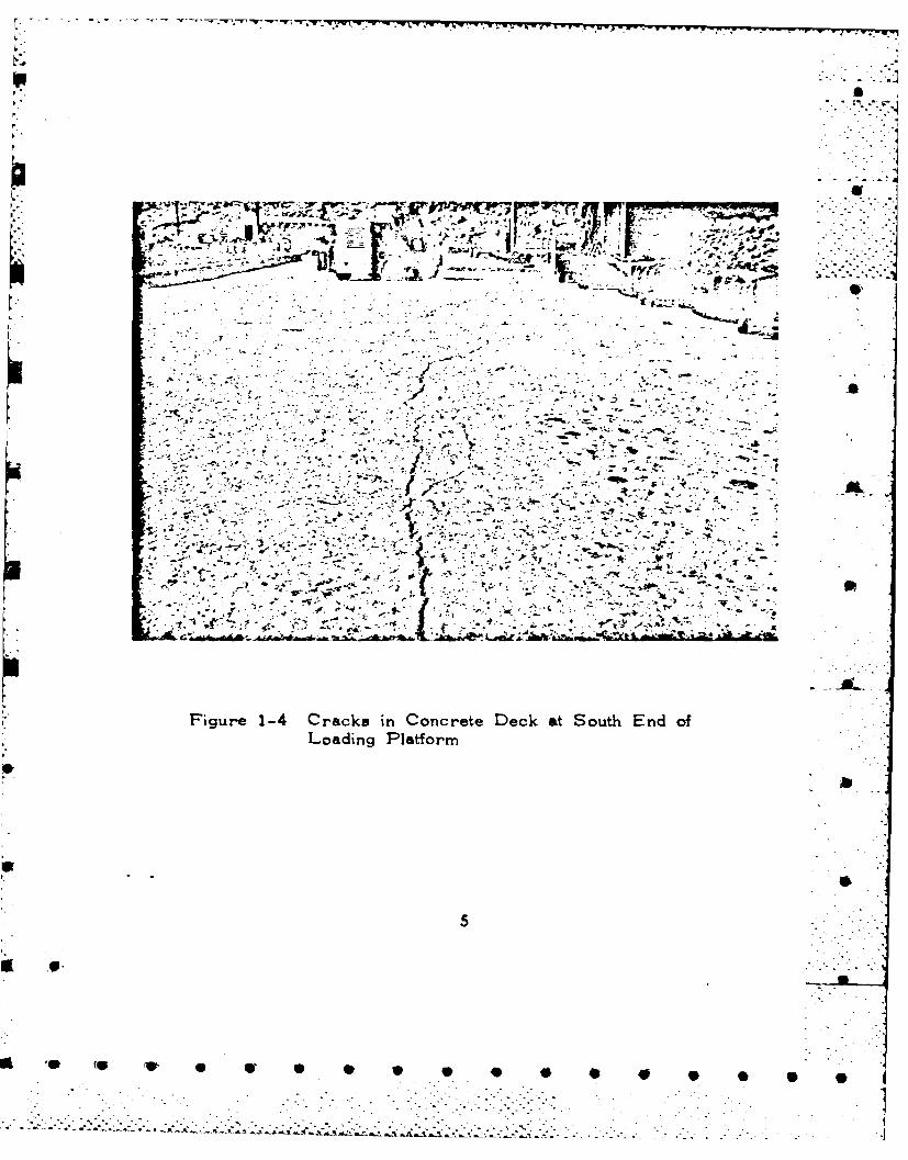
According to the documented records, the pier has deteriorated since itsoriginal construction (see Appendix A of this report). The deteriorationof the pier resulted in the spalling of the concrete around the pile caps -*
and cracking of the concrete deck of the loading platform. Figures 1-3 . . ..-to 1-5 illustrate typical damages of the pier structural components.
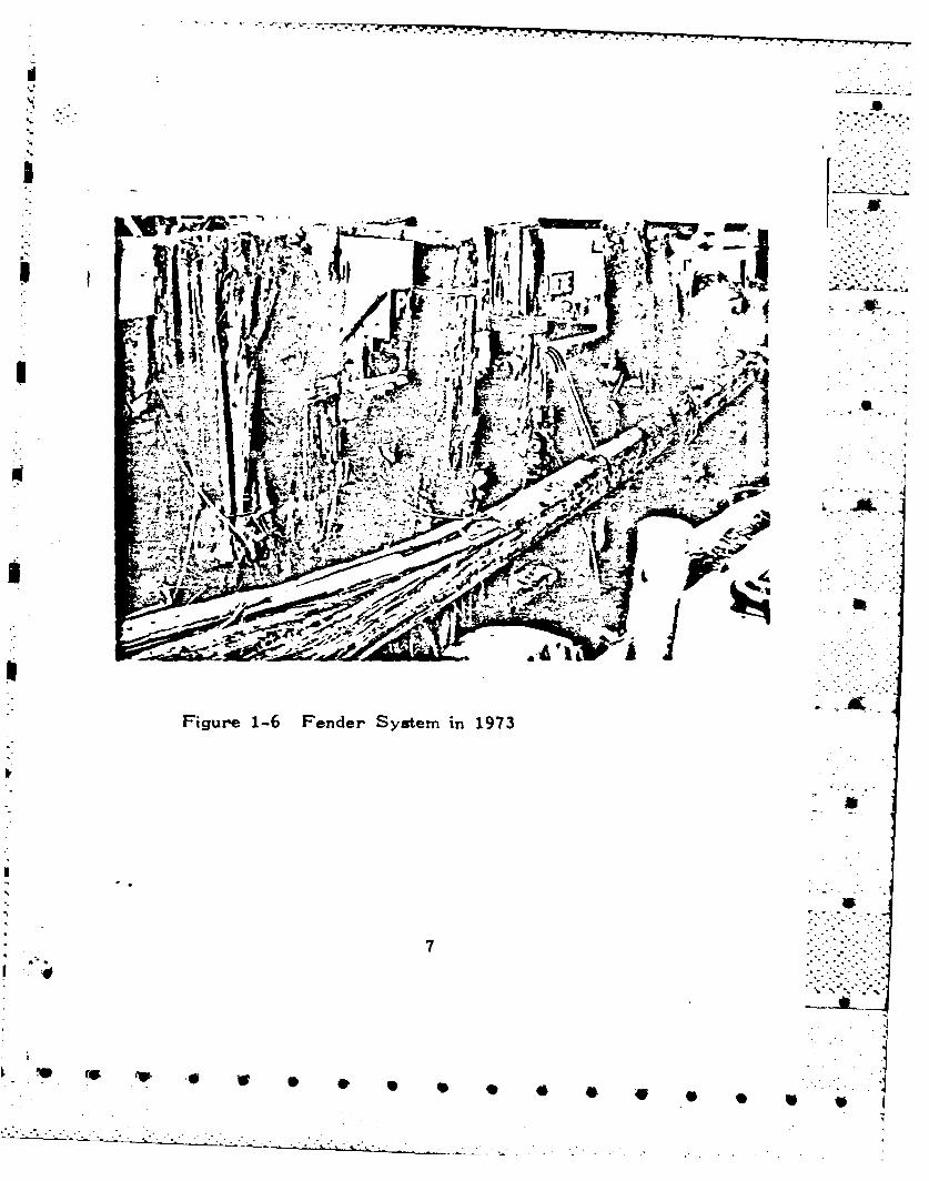
Deterioration of the pier also includes general biological attack andoperational damage to the protective fender system. Figures 1-6 and 1-7show conditions of the fender system in 1973 and late 1977, respectively.A substantial improvement in the appearance of the fender system has beenachieved. However, repair and maintenance of the fender system bas becomea continuous requirement.
Compounded by the high maintenance costs, inordinate consumption of man-power at the Civil Engineering Squadron (CES) and the possibility of majordamage occurring to the pier structure or to ships, the Commanding General -
at Lajes Field requested the Military Airlift Command Headquarters (MACHQ) - - -for engineering assistance.
1.2 Tasking
The Ocean Engineering and Construction Project Office (Code FPO-I),-Chesapeake Division, Naval Facilities Engineering Command (CHESNAVFACENGCOM)was tasked by MACHQ to carry out the engineering assistance to the CES atLajes Field. The missions of the tasking were as follows:
.0 ,- -N
-. ~ -- - ~ -~ .• - .2 .* .A *,-. .

LaTo -N
-r -
- ~ -. .~Ila
VI - 14 Xj
TS AL
of
* Z I.

7FlI
* -io
II
544

44V
* r~ o- at
- ~ X _ ,~0
1 '-4 a.
Figre1-3-
a~ w 9 0 4
AA
~ ~ - '7
joJ
fai ,
Figure~~~~~~~~ 1-4 Crcsi ocrt ekaSuhEdo
Loain Pltfr
.. , ~ ~ &.r ~ ~ -'5
40 4p

- jr
t4. v~Z2*I" 4-I -'.AL-~ i~ ~4m ~ en.-
C- N..?.~
4 7A-. . ->.* C.%*~ V cc
if's.
"~)tVIA.
Figure 1-5 Concrete Spalling at Pile Cap and Cracks in* Frame Beam
or
6 i i
%Mi
3 -~®r
~ rL-Lir 1-6~' FedrSse n17 IA
2'7
1 6o
7--1 ps7-.J ~ W.7V'-
AA
bd .
Figure 1-? Fender System in December 1977
1~~~ 4 *. . 4P 0 0 v

* An on-site visit by a marine structural engineer
e A technical evaluation and analysis of the existingsituation
* A report of recommendations showing what structural ... ,modifications must be made to the pier in order toaccommodate POL and cargo ships of the 40,000 ton size.
The tasking message and the financial support information to this missionare included in Appendix A of this report. " '
1.3 Field Investigation
In responding to the MACHQ tasking, an FPO-1 engineering team, consistingof LT J.C. Wright and Dr. C. Chern, visited the POL pier site during theperiod of January 31 to February 3, 1978. The objectives of the teamvisit were to: f
" obtain design and operational data of the pier structure;
e inspect the damages of the structural components;
" inspect the existing fendering system; and
" diving inspection of the pilings.
The list of the pier structure drawings is shown in Appendix B of thisreport.
1.4 Findings and Possible Solutions
The findings of the POL pier inspection are as follows:
(a) Spalling of the pile caps and cracking of the concrete deckon the south bent of the loading platform were due to lateral loadsapplied in excess of the component strengths.
(b) Original fender system has deteriorated. The pile componentsare replaced at highly uneconomical frequencies.
(c) The POL pier appears to be an excellent vertical load carryingstructure, similar in design to a bridge. However, the pier does notpossess sufficient bracing to resist lateral load induced by ship berthingmotion.
The possible solution to item (a) above is to apply cement or epoxy grouting
to the cracks. Pressure grouting will not increase the strength of thestructure but will protect the exposed reinforcing bars and the steel pilesurfaces from environmental corrosion.
9'

A new fender system consisted of fender piles with cylindrical rubberfenders is suggested for the possible solution to item (b) above. Itis noted that the principle function of the fender system is to preventminor impact and heaving abrasion damage to the ship and/or the pierduring mooring. The fender system will be designed only to transfer theforces from the berthing ship to the pier structure. Hence, the new fendersystem will not reinforce or increase the strength of the pier.
The possible solutions to item (c) above constitute the major portion ofthis report. The suggested plans are:
e Loading Dolphin Approach - The plan calls for the constructionof three loading dolphins in front of the loading platform toresist the impact force from berthing ships. Thus, the
pier structure will be free from direct impact of larger 4
size ships.
* SBM System Approach - The plan calls for the installationof a single buoy mooring (SBH) system outside the break-water. The ships will moor to the SBM and then transferthe liquid fuel shoreward through submarine pipe lines.In this system, the oil tanker will not use the existingPOL pier.
The briefing at the Command level at Lajes Field following the investigationis documented in Appendix C of this report.
I 10
A00q* * , * * * * *_
,-4 •" .. -

- - -- rr-- .......~- .
CHAPTER 2. EXISTING POL PIER AND ENVIRONMENT
2.1 Introduction
The POL pier consists of a loading platform, four mooring dolphins, traffic Sbridges, and walkways. Figure 2-1 illustrates the general arrangement ofthe pier system. The bridges to the north of the loading platform are 12feet wide and are designed for HS20-44 truck loading in accordance withAASHO specification (See Appendix B.1 File No. 7571-5782 of this report).The walkways to the south of the loading platform are 5 feet wide and - --.are designed to carry 100 psf uniform live loads. The supports to thebridges and walkways are all 12 3/4" 0 x 1/2" WT steel piles penetratingapproximately 40 feet into the seafloor.
Mooring dolphin No. 1 is supported by a steel sheet piling cofferdam withstone backfill and mooring dolphins Nos. 2 to 4 and the loading platformare supported by a series of 16" 0 x 1/2" WT steel pipe pilings. Both •the dolphins and loading platform are designed for T-2 class tanker mooringsat 65 MPH wind conditions.
Fixed wooden pile fender systems are attached to the loading platform andmooring dolphin No. 4. The original fender system has deteriorated andthe replacement of wood fender pilings has become a continuous operation.
2.2 Subsea Soil Data
Subsea soil data in the vicinity of the POL pier site are available(See Appendix B.1, File N. 7571-5783 of this report). Figures 2-2 to2-4 depict the boring logs of sites Nos. T-3, T-5 and T-8. The approximate Slocations of the boring sites Nos. T-3, T-5 and T-8 are shown in figure 2-1.
The seafloor materials in the vicinity of the pier site are composed ofa black volcanic sand with a high shell content which gives it a "salt andpepper" appearance. Based on the results of mechanical analyses of samplestaken from boring sites, the materials along the shore and immediate off-shore area generally consist of a well-sorted sand with the mediam diametergrain size falling predominantly in the range of fine sand.
The sand layer is approximately 40 feet deep. Hard basalt lies thereunder.
2.3 POL Pier Structural Component Strength
The loading platform is the prime structure of the POL pier system. Theplatform consists of a concrete deck 200 feet long by 40 feet wide supportedby a series of 16" 0 x 1/2" WT steel pipe pilings. The plan view of the-concrete deck and the cross-section of the platform are shown in figure 2-5.The wooden fender system is attached to the shipward face of the 60-foot Ssections on both ends of the concrete deck.
The structural component strengths calculated in this section are thebasic factors defining the ultimate strength of the loading platform under
41
= --• . ,_ ' " " . ."° "" • " -'• , . - . . .- " . '." - " . .
IQ-~
* ~IC
-
ION)
r ,"b
L-C-
0 .C
-.. 4
12
1 "
...-.
- .
..
"

T-3ELEV 0.0if l0T, 260E 131, 064
JV
Av'
soas. ors toasof
1313 9
,J.I?
Aw. I'
s ~ . tr c a W
sw?.al
r bO. ly~* 810.d to~ V. AI I
Fiur 22 oi Boig LogI~ 9Site No -
13
fe w. v V w 0 6 0 40 4 4 4* 0 0 6 0

T-5FLEV. 0.0" 107616 .,C 130-36
tMW
41• j
* ..
1r4 5 .- ---, . ".. isso SOW) P. .l"r pp" "?
0 to P . Ij5d4 I1
.3fr.-" -
.. . C-,.',Pf . P
J.j /o *M,,A pry .~ F* SACV A SILt
.. 10
. r
1, -a.." f e OW 1V. IlPt. f.)
Figure 2-3 Soil Boring Log -- Site No. T-5
14 7
W 0 0 0 4 V M- , a*,__ I. _ _ _.*
_;.. ! co iP. . . . . . --. . -• •
T-8ILMV 0.0N 10,5239 130 6 09
f?
toL _
JV~
"WI,'h. indvw e f4ry S.#C* aWJ./f. $AV.. .-"1).
it,. If" . "1s s.- _ff ... f.37fe# -
.60.
* dl
ity & ~1...SAVDO f I f t (.1IfI P. rd..). r GRAVLM
J~f-j .. 8*,' . . ?.)
it. doIN
OevfA fr.. AI9AIy ff zl,pA fly
110
/ta.SIt. A CLJV Pr 1.1
Figure .2-4 S oil Boring Log -- Site No. T-815
Q V.
0- o
r~ 'i-IL
Q SO 0
91 Ln
j
14.
160
0 w p 0 I H e
..- v.._.-.--.-
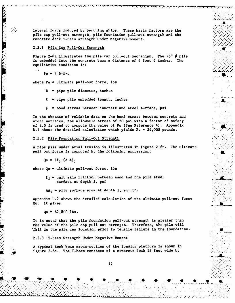
lateral loads induced by berthing ships. These basic factors are thepile cap pull-out strength, pile foundation pull-out strength and theconcrete deck T-beam strength under negative moment.
2.3.1 Pile Cap Pull-Out Strength w
Figure 2-6a illustrates the pile cap pull-out mechanism. The 16" 0 pileis embedded into the concrete beam a distance of 1 foot 6 inches. Theequilibrium condition is: ."".''
Pu A 7 DL''P
where Pu ultimate pull-out force, lbs
D - pipe pile diameter, inches
L - pipe pile embedded length, inches
bond stress between concrete and steel surface, psi
In the absence of reliable data on the bond stress between concrete and " -
steel surfaces, the allowable stress of 20 psi with a factor of safetyof 2.0 is used to compute the value of Pu (See Reference 4). Appendix
* D.1 shows the detailed calculation which yields Pu -36,000 pounds.
.'- 2.3.2 Pile Foundation Pull-Out Strength
A pipe pile under axial tension is illustrated in figure 2-6b. The ultimatepull out force is computed by the following expression: .
Qu Efi (A A)i
where Qu ultimate pull-out force, lbs
fi unit skin friction between sand and the pile steel -. - "surface at depth i, psf
AAi - pile surface area at depth i, sq. ft.
Appendix D.2 shows the detailed calculation of the ultimate pull-out force -.-
Qu. It gives
Qu - 62,800 lbs.
It is noted that the pile foundation pull-out strength is greater thanthe value of the pile cap pull-out strength. Therefore, the pile will"*ail in the pile cap location prior to tensile failure in the foundation.
2.3.3 T-Beam Strength Under Negative Moment
, . A typical deck beam cross-section of the loading platform is shown in5 -figure 2-6c. The T-beam consists of a concrete deck 13 feet wide by
17
W4. WW- W .-. . . ..- , , . .
.*a ,- . '::':I .. m.., ,t '.._,. 1I+"..." "."* *"iiI >*: ',, ; . .."f"""""" •"" '-.•. .-.. ."., . .-" .

* .. *I * .
-- nI . . . .
I- 'IL I ... w--4 -
. .. *-, o
------ j-U - -I *-'
1' .=" -- . z". .4
; ""T ® .0a., 0, I .. •
if- ,.- - " "- " .'. '.- ..
.. s i''." .'. .-.'' A
-° ' 11 7XA o°I U- % % -.
i'" I ".i. '. °
".-I...
[.--- _ . .. . . . .. . . . . ; ,. -- -- -.- . . ..... ... . . -C.0
["-. ,.",," .'. .. "- ." . .'" "" . " '.' .".-'. . ' . . ' . .- " - "- ' .' " . r" • " " 3["..',.'-,'-."-".~~C V1"" -" . ".•". . - -- ..t-'.-,..' -',. .'...,-. ' ." ..' " . .-'.. --" .. . . .. . . . .
• " % V' ' '
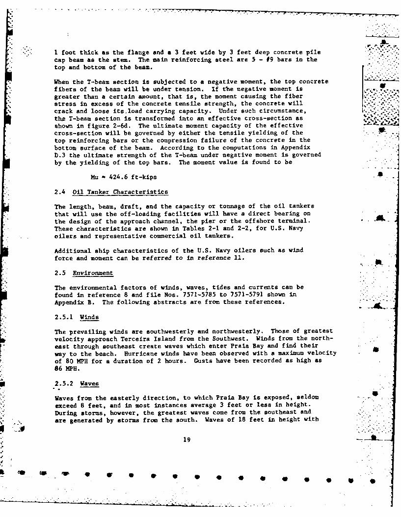
I foot thick as the flange and a 3 feet wide by 3 feet deep concrete pilecap beam as the stem. The main reinforcing steel are 5 - #9 bars in the
., top and bottom of the beam. [When the T-beam section is subjected to a negative moment, the top concrete "fibers of the beam will be under tension. If the negative moment is . ...
greater than a certain amount, that is, the moment causing the fiberstress in excess of the concrete tensile strength, the concrete willcrack and loose its.load carrying capacity. Under such circumstance, ,....-the T-beam section is transformed into an effective cross-section as .__.__shown in figure 2-6d. The ultimate moment capacity of the effectivecross-section will be governed by either the tensile yielding of the . -
top reinforcing bars or the compression failure of the concrete in thebottom surf 'ace of the beam. According to the computations in AppendixD.3 the ultimate strength of the T-beam under negative moment is governedby the yielding of the top bars. The moment value is found to be
Mu - 424.6 ft-kips -a
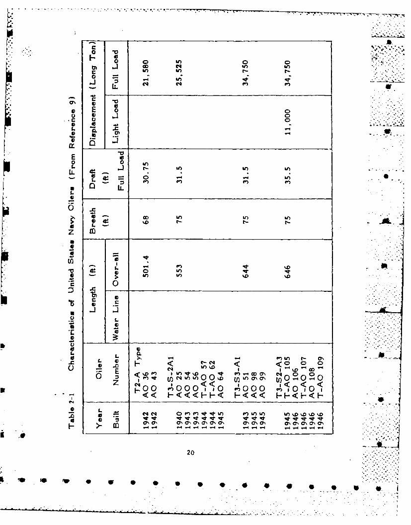
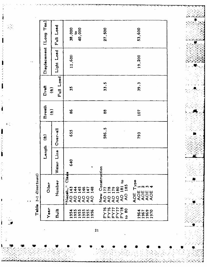
2.4 Oil Tanker Characteristics
The length, beam, draft, and the capacity or tonnage of the oil tankersthat will use the off-loading facilities will have a direct bearing onthe design of the approach channel, the pier or the offshore terminal.These characteristics are shown in Tables 2-1 and 2-2, for U.S. Navy
- . oilers and representative commercial oil tankers.
Additional ship characteristics of the U.S. Navy oilers such as windforce and moment can be referred to in reference 11.
2.5 Environment
The environmental factors of winds, waves, tides and currents can befound in reference 8 and file Nos. 7571-5785 to 7571-5791 shown inAppendix B. The following abstracts are from these references.
2.5.1 Winds
The prevailing winds are southwesterly and northwesterly. Those of greatestvelocity approach Terceira Island from the Southwest. Winds from the north-east through southeast create waves which enter Praia Bay and find theirway to the beach. Hurricane winds have been observed with a maximum velocity -
of 80 MPH for a duration of 2 hours. Gusts have been recorded as high as86 MPH.
U 2.5.2 Waves
Waves from the easterly direction, to which Praia Bay is exposed, seldom - ""
exceed 8 feet, and in most instances average 3 feet or less in height.During storms, however, the greatest waves come from the southeast and
*:'- are generated by storms from the south. Waves of 18 feet in height with - "
19
.4F
tn OD 04 f)0
LLC
Sn%0 4
oo 0O U
IL Ln
CI C4 <
0n Ur CU, %nL UnCI 0 40 1
qt S. q t c ~ON aNON cl Na s NCNcsaU. - - - - 4 T4 v. 4 V- - -
02
o~ r~
c oo 0
E 00C
o 4 0
o LL'
CID t-0. .COD
0
4))
-E t4vv -t t o F
0-0000 00000 00
z
4.121
(w (W fo 4P

0 V
I---. 0
go 0
o.
0- - ',-.. -
00 . .... f.
0 • ° ,- .°,0
.- •- .- .
LiL
ID
L .. .. ,
In
LO C4
0 ' :
0
00000 06) 0 .
< <<<<<<< -cIE'oo00000000 U.)PI,,
w '
" .- ~~~~ ~O a -0 , CYN C" l O O CY N O (7 , a % .. .'"7.-N- .
1- V-4 --
- - - -- - - - ...-V .- "-" " -. ' - " - " ". " - "
o LL
'43SL
L) .~ .. .
m N 4t 0 O 0 W) -4 U) O -) -l -
-4 - 9-4 "q-4 .- f -4 -4 C4~
E3 0
*C
0 - m % -nN k 0 g r-4C* L 00 C-4 LO4 OD4 0- M O-$7 I
LO W D% -c C P 4e
0 E* -0 -----
-4 CC 4tL
. Or
o *o00~0u')0000O0000
Im c
v 0 0 4
*1~rr~ . r. -- r r r r' ----- .r. - ,
the period of 9 to 11 seconds were recorded during winter of 1955 at the,-'
old breakwater in Praia Bay. The duration of these 18-foot waves wasapproximately 12 hours. Information on storm waves indicates that waveheights at the new breakwater during the storm of December 1962 wereestimated to have reached a maximum of 25 feet. The wind velocity during .this storm was of 25 to 40 knots east winds. v
2.5.3 Tides
Tides in Praia Bay are semidiurnal with a mean range of 3.7 feet, and aspring range of 4.9 feet. Highest high water is 5.0 feet above mean lowwater and lowest low water is 1.7 feet below mean low water. -
Strong east winds tend to increase the tidal height in Praia Bay, whilestrong west winds will tend to reduce it. Information on the frequencyand amplitude of storm tides are not available.
2.5.4 Currents
Current measurements were performed inside Praia Bay. The resultsindicate that there is a clockwise rotation of water in the northernsection of the bay. The currents are relatively constant with depthand no appreciable change in direction with depth. Current velocitiesinside the bay vary from 0.00 to 0.80 knots with the maximum velocityto the southeast end of the bay.
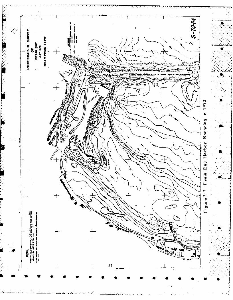
2.6 Harbor Soundings
The harbor soundings in the vicinity of the POL pier are shown in figures2-7 and 2-8 which were surveyed in 1970 and 1977, respectively. A directcomparison of the seafloor elevation at a specific location can not beobtained from these two sounding diagrams. However, an approximate 300feet wide by 35 feet deep approach channel to the POL pier appears tobe properly maintained throughout this period.
. .. " ._
": . @ -- '.--',
24
-- I. -
FA~
4,,-r S*1
4 -III -
1 16'
4 a -~JR
.........
~~~~~~~~~~~ - r:o~*.* '~.~-~ ,--
. ~ - . . - -
* I 25
40 40 4

an~~~~ or .'-,'., H/, Is w
=a Or MW T+ t .cpAur 1
MIELa -C/NAtr- OR MAR1161
•AD
,
.1 _ _ _ _ _ _ _"__4
XF
__ _ __ _ __ _ _ __ _ __ _ _ p"1 .
K-.- ..
22
* S
Figure 2-8 Praia Bay Harbor Sounding in 1977 -",-* 26 5
-. - *--.----- - -.-. ..... ... - . ~- - - - - -...
CHAPTER 3. FENDER SYST"'
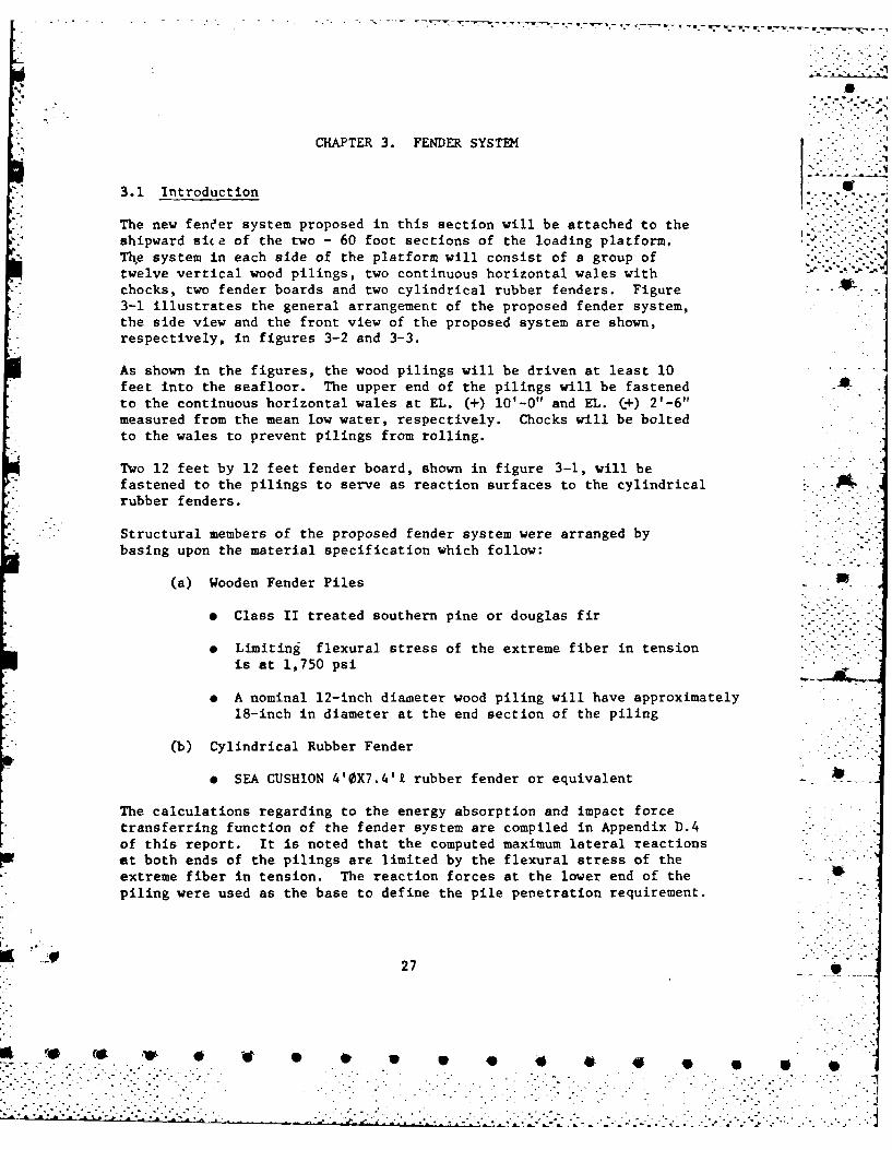
3.1 Introduction
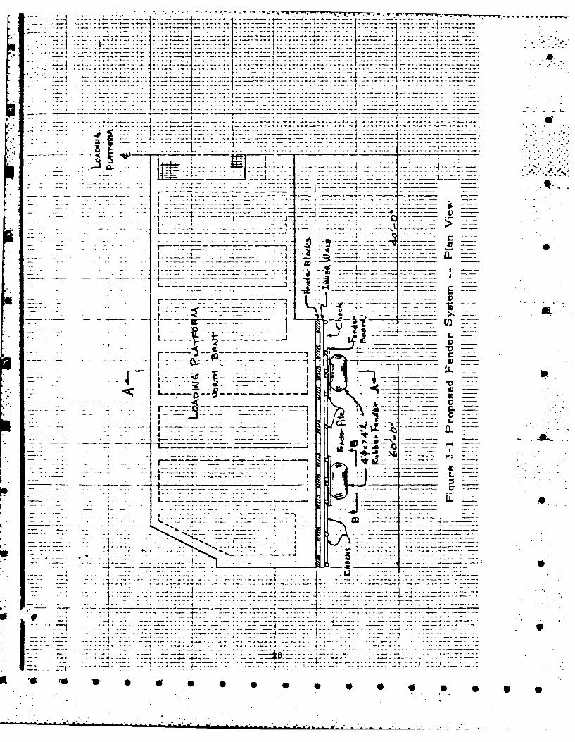
The new fen'er system proposed in this section will be attached to theshipward sice of the two - 60 foot sections of the loading platform,The system in each side of the platform will consist of a group oftwelve vertical wood pilings, two continuous horizontal wales with ""chocks, two fender boards and two cylindrical rubber fenders. Figure -
3-1 illustrates the general arrangement of the proposed fender system,the side view and the front view of the proposed system are shown,respectively, in figures 3-2 and 3-3.
As shown in the figures, the wood pilings will be driven at least 10feet into the seafloor. The upper end of the pilings will be fastenedto the continuous horizontal wales at EL. (+) 10'-0" and EL. (+) 2'-6"measured from the mean low water, respectively. Chocks will be boltedto the wales to prevent pilings from rolling.
Two 12 feet by 12 feet fender board, shown in figure 3-1, will befastened to the pilings to serve as reaction surfaces to the cylindricalrubber fenders.
Structural members of the proposed fender system were arranged bybasing upon the material specification which follow:
(a) Wooden Fender Piles
* Class II treated southern pine or douglas fir
e Limiting flexural stress of the extreme fiber in tensionis at 1,750 psi
* A nominal 12-inch diameter wood piling will have approximately
18-inch in diameter at the end section of the piling
(b) Cylindrical Rubber Fender
* SEA CUSHION 4'0X7.4't rubber fender or equivalent
The calculations regarding to the energy absorption and impact forcetransferring function of the fender system are compiled in Appendix D.4of this report. It is noted that the computed maximum lateral reactionsat both ends of the pilings are limited by the flexural stress of theextreme fiber in tension. The reaction forces at the lower end of thepiling were used as the base to define the pile penetration requirement.
27
'iJ 4. (0 * i . . . * * * * * * *
-: , . ,,, .. , .. ,,. .. . ... .... _. :" -.i~ ~i 2 .iii,. .j ::.,;2;.:. . ;?, .:..i: ... :: ,--.-...- --.- - . .*.,..-
, ~~~~~~~~ .... _..... .. ..... . . .. .. ... ..
... 7 --- .--.-.--.--.-. ----
--.. . . ... ..5 ] . . t .... . . ..:-. . ..-.. .. .. . ... .. .
- AL
. -- --- --- --- - - -
.. . .. .* :: "'2 ' ... . i:2 7? l . .. i " -- . . . ... . . .
. . - -- ... . . . .. . .. .. . - : - . - _-C-._ - . r -- _-- . - --- -- 'I -- ---- _0... .
.... ... I -4 ' -:+-:--:- -- ;--: 1 ~---" '-'-"-
- t.:- :' - -2: - - " "- -1 7 __
!i-71. 1- __- - - "L
._ - - . - . . , :: . .-- - _- .- __----. __ -i- . . . 27- I_ _ _ D-1 - :: . : : .. .. .- ,- * -- . .i ,- -. .. .. .. . ' <-: i-, "7Z L
... ... L... J -u . . . ..
..... - - - 12 1Z7" - 0 _ _--7:
- -. - . r 7 --, . ._..- -. .. ..... - :: --... . --- ': -- -: ' I!: _-__ - W :--
- *. . • - 4 . . "- . . . . . . ... . ...- - -". ..- : -- - .... . ........ __..... I - - .---.-- I
. .. , - - - - = - - - _ " ._ _ .___.__ ._-
• ] 2 -,**::- i i -. ... .... .. .
- -:4 2. *- . ;:--: : - , .. .-.. . . .. ..- ; - :: - -. :--- - .- :- ".. .. .- .. . .. .. .. .. . . . .,...... J .....tU : : . . .I-. . . . . ...... .
.. ... } ............. ...... ........ .................... ....: . . . : : . : :: : : : , : : : : : : : : : :: : : : : : : : ::: : : : : : : : : : : : :: : : : : : : : : : : : : : :" - • i -i : : : : . : : , : : : : :: : ::: : : : : : : : : : : : : : : : :: : : : : : ::. : : : : ; : : : .. : :.
. = _= =:= .;= ==.;"=T-=- =- - == = === -: _=,= : ===.= = == : :: - .-
• _* r , * *- _*-* :*

-l W -7T .- -- . -r-% .- W-.--
77 Z:,-7 :7
-~ .z..4. J.~e 7- -
-47- -- I
_ _ _ _ _ : -_0
- 0-
CL1
-:7
-~ ~J...........
F'gu' -2 rpsd1edr ytm-Ve -
z; j~UUZ.t7~i~j7--...~ 4i~lJ~iiL~ -- . :
* I I . . - ..-.--.-.-. 7-
Fi ure Proposed7 Fender~7Z Syte Vie A
*4 4 S P S S 0 0 0 S S

7:17
-4-.
w.4t.4A4t+) --IA
E--t
_7 _ 4-
.
------ ----. . . ._____~-7 7t- . - '- .~
7.
-4.
* Figure 3-3 Proposed Fender System -- View B-B __
:771
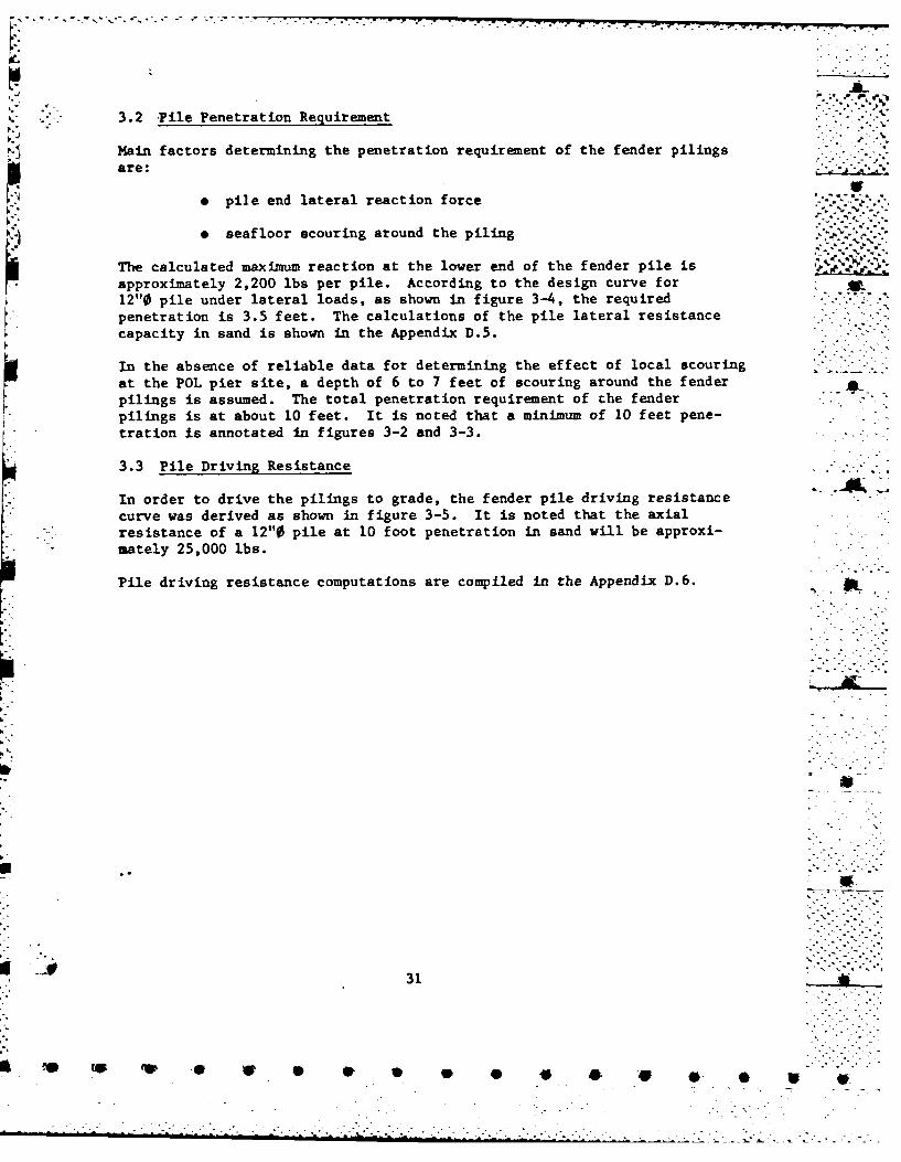
3.2 Pile Penetration Requirement
Main factors determining the penetration requirement of the fender pilingsare:
- pile end lateral reaction force
. seafloor scouring around the piling
The calculated maximum reaction at the lower end of the fender pile isapproximately 2,200 lbs per pile. According to the design curve for12"0 pile under lateral loads, as shown in figure 3-4, the requiredpenetration is 3.5 feet. The calculations of the pile lateral resistancecapacity in sand is shown in the Appendix D.5.
In the absence of reliable data for determining the effect of local scouringat the POL pier site, a depth of 6 to 7 feet of scouring around the fender -pilings is assumed. The total penetration requirement of the fenderpilings is at about 10 feet. It is noted that a minimum of 10 feet pene-tration is annotated in figures 3-2 and 3-3.
3.3 Pile Driving Resistance
In order to drive the pilings to grade, the fender pile driving resistancecurve was derived as shown in figure 3-5. It is noted that the axialresistance of a 12"0 pile at 10 foot penetration in sand will be approxi-mately 25,000 lbs.
Pile driving resistance computations are compiled in the Appendix D.6.
31
0 .4P
.. .. ... . .. . .. . . . . .. . . .. .. . .... , .

U)
Z
IV /0
0 0
U)S)
4..q6
-j IID<
J
.000
2 C2
qF N

DRIVING RESISTANCE IN SAND(12" 0 Nominal Diameter)
(KIPS)
0 5 10 15 20 25 30a. . 0
IL-2
Uwz
3
05nUj
COi
z0
-7
w 9
10
Figure 3-5 Fender Pile Driving Resistance in Sand
33
F.4 w4

CHAPTER LIMITING STRENGTH OF EXISTINGPOL LOADING PLATFORM
4.1 Introduction
The structural strength of the existing POL loading platform is evaluated " '-'in this section. In the process of structural analysis, the platformstructure is approximated by a series of plane frames spaced evenly alongthe longitudinal axis of the platform. The plane frame structure consistsof a horizontal concrete T-beam and four steel pipe columns. Two exteriorcolumns are vertical and two interior columns are inclined at 2.5 to 1slope in an opposite direction. The four columns are embedded into theT-beam stem. Section A-A in figure 2-5 illustrates the beam-to-columnconnection of the plane frame. The four columns are assumed pinned atthe mud-line. A horizontal load is applied to the frame at the concretedeck level.
4.2 Pile Cap Pull-Out Mechanism
When the horizontal load P1 is gradually applied to the plane frame,the structure will deflect accordingly in the direction of the appliedload. An exaggerated deformed shape of the plane frame is shown in figure4-1a. Due to the deflections of the two interior columns are in theopposite direction, the concrete T-beam will be forced into a double-curvature deformation. As shown in this figure, the critical conditionis at point C (or C') where the concrete T-beam is under positive momentand the steel pipe column is under tension. The maximum pull-out resistanceof the column is 36,000 lbs (see § 2.3.2). The corresponding strength ofthe horizontal load P1 is found to be
P1 - 27,000 lbs.
The structural analysis of the plane frame failed by the pile cap pull-out mechanism is included in Appendix D.3.
4.3 T-Beam Failure Mechanism
After the pile cap has been pulled out, the concrete T-beam will transform
into a single curvature deformed shape, as shown in figure 4-1b. Undersuch circumstance, the concrete T-beam at point D location will be subjectedto a negative moment. It is noted that the negative moment capacity of theT-beam is 424.6 ft-kips as discussed previously in 12.3.3.
The horizontal force P2 , limited by the tensile yielding of the T-beamstrength is
P2 39,400 lbs.
Appendix D.3 also compiles the structural analysis of this case.
I.
34
- . , "7 --

.*......... I.
AL.
iL
CC)o
355
-w *-J 0 w

-7 - MR "- -. -_ -2
4.4 Berthing Velocity Limitation
The possible failure mechanism of the POL pier due to the impact loadsof the berthing ships may be sumarized as follows:4 (a) Fender System 6
9 Fender pile bending failure
e Lateral load resistance failure at the lowerend of the piling
() Loading Platform Structure
* Pile Cap pull-out failure
o Tensile yielding of the concrete T-beam undernegative moment
In order to prevent the above mentioned failure mechanisms from occurring tothe POL pier structure, the limiting berthing velocity of ships is derived.
The kinetic energy for ship to jetty or quay service is calculated fromthe following relationship: L.-, :'
CB W V2
2g
where E - the kinetic energy absorbed by the pier system A
CB = berthing coefficient, 0.5 (see references 6 and 11)
V = berthing velocity
g - gravitational acceleration
W -Wa + Wb
Wa - added mass tonnage
Wb - actual displacement tonnage at the time of berthingoperation
In most cases, the added mass tonnage can be approximated as 60% of theactual displacement tonnage, or
Wa = 0.6 Wb
36
-"-.L. '-. .. ... ."-__ ____ _ - i -. 4_ -- , ..-
7 - -- F -a- • .- ,-
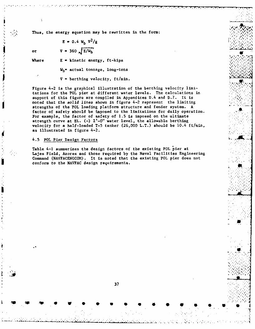
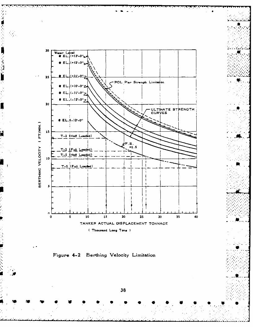
Thus, the energy equation may be rewritten in the form:
E -0.4 Wb V2/g
or V -360 FE/h
Where E kinetic energy, ft-kips
Wb- actual tonnage, long-tons -.-
V - berthing velocity, ft/min.
Figure 4-2 is the graphical illustration of the berthing velocity limi-tations for the POL pier at different water levels. The calculations insupport of this figure are compiled in Appendices D.4 and D.7. It isnoted that the solid lines shown in figure 4-2 represent the limitingstrengths of the POL loading platform structure and fender system. Afactor of safety should be imposed to the limitations for daily operation.For example, the factor of safety of 1.5 is imposed on the ultimatestrength curve at EL. (-) 2'-0" water level, the allowable berthingvelocity for a half-loaded T-5 tanker (26,000 L.T.) should be 10.4 ft/min,as illustrated in figure 4-2.
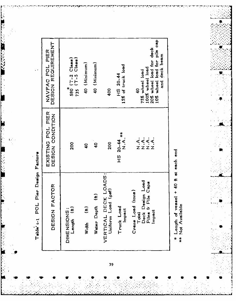
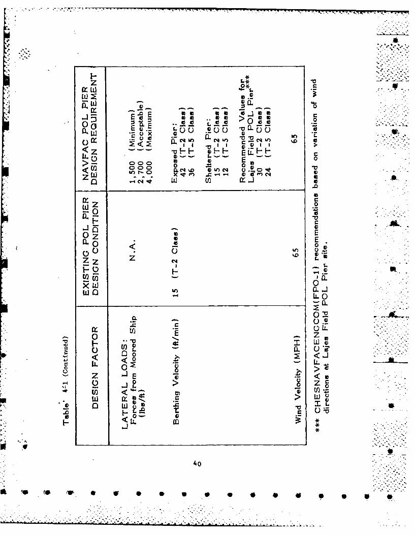
4.5 POL Pier Design Factors - .
Table 4-1 summarizes the design factors of the existing POL pier at" - Lajes Field, Azores and those required by the Naval Facilities Engineering
Command (NAVFACENGCOM). It is noted that the existing POL pier does notconform to the NAVFAC design requirements.
IL
. * -,-
37
- .. -P .
30
POL Pier Stre.ngth Limti on
0 EL;()1ol ~N
T-EL (-)2 -0ad Z.
EL. -)10
Is
LTouan T-2~ Haf oo.d
FiT-2 4F-2 Berhig elciy imtio
T- al ode)I
138
L . .. . * *
* 06
zF
0.9 E
-.J 0 L
0 - 0 00-
I I IC -
<~~- -. C . 777,c
LL L C 0 0 0 X..>p co 0
wz-o
0 Z00
Z cl Cq oz Z ZZ
ix CL* WQ 0
01 0)
*~ Os
0.uz 0 u-
E- 0-o < L -0
z
0 J :3 J- 00w
93
nw V W 0 0 to *p * ,
'II.
z3 z >
-a x.
4.0 0.- '0
000 o )>U 000 0 ::t 0
<~ EO C14v C. %)O 4)A)c
0, LI ti) 0
0 Z0
U)
02
=00
0 < 06)0 >
IZ 4)
LIIJ
04
a, 4

I.-1
.- V -
P0
F.- U
00 0 -Y
L.. 0
4.4.. L. 0L C
u0 < zs.LO 00 Z r
L 0
ON 440~
z it
F- tz 0
X 4)0.
ul EL
It-_
:2 Z-* 0J- 4
441
's~~ F- C) L * * *
0 . . .
- - ... .- ,- . A.....>. -ix

" . . - -.- SJ. .- :. . .w L -j-Jnp- -..- .-r.r.r - .- r r .r .-.. b ... . .......
CHAPTER 5. ALTERNATIVE APPROACH I--LOADING DOLPHIN SYSTEM
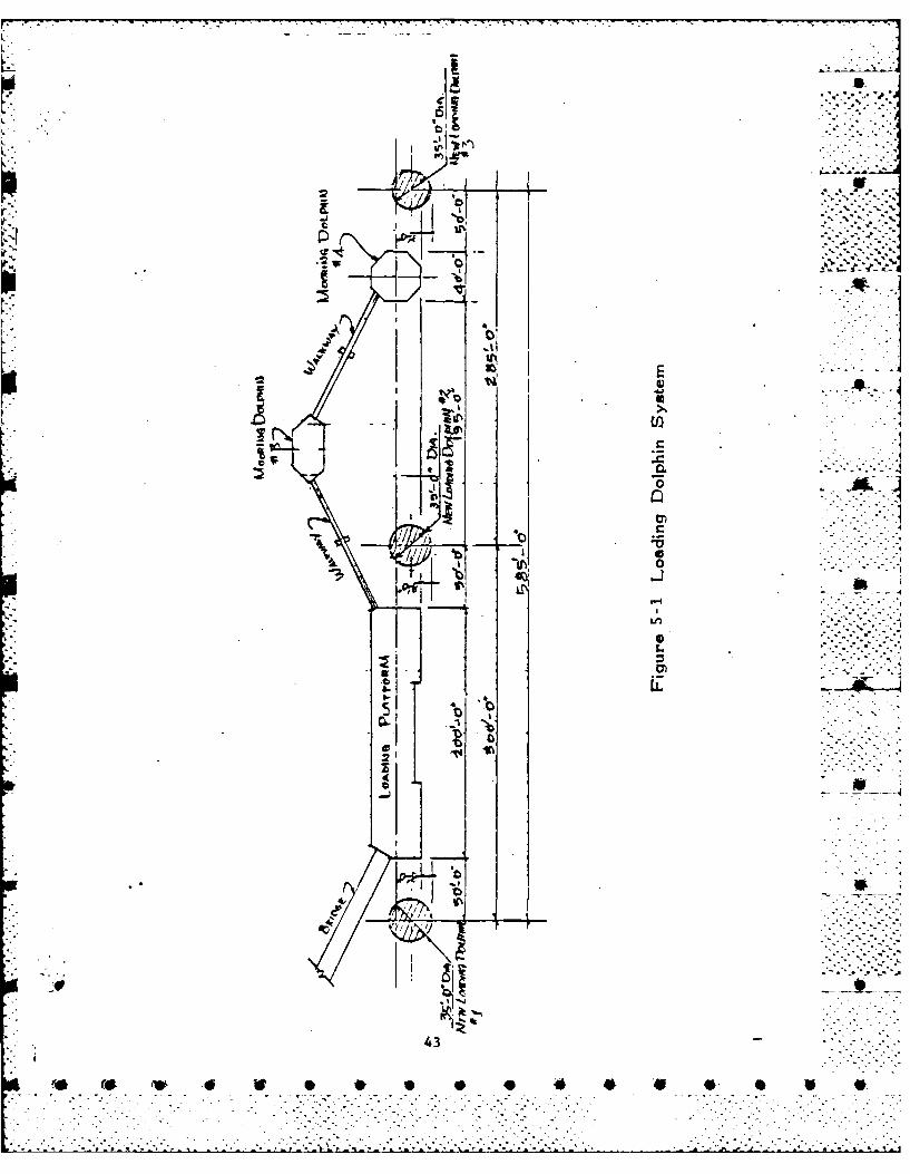
5.1 Introduction .
The main concept of the loading dolphin system is to construct three
lateral load-resistant dolphins to prevent the loading platform fromdirect contact with the berthing ships. Figure 5-1 depicts the proposedsystem. It is noted that the system shown in figure 5-1 is similar tothe POL Pier Modification originated by the Army Corps of Engineers, . -.New York District in June, 1966 (See Appendix B.2). The added dolphin(No. 3) is for the accommodation of the T-5 class tankers.
5.2 Loading Dolphins
Lateral load-resistant dolphins will be subjected to impact loads at 0water line level induced by the berthing ships. Hence, the functionsof the dolphins will be to resist the horizontal impact force and thecorresponding overturning moment. Depending on the methods of counter-balancing the applied loads, the following two types of dolphins may beconstructed in this system.
5.2.1 Friction Resistance Type Dolphins
Figure A-3 of Appendix C, illustrates the basic components of the frictionresistance type dolphins. Steel sheet pilings will first be driven to therock bed to form a cofferdam and then filled with stones. A huni fendersystem above the water level will be attached to the dolphin.
The horizontal load applied to the dolphin will be resisted by the frictionforce between the sand surfaces at the cofferdam base level. The over-turning moment will be counter-balanced by the gravity of the backfills.Appendix D.8 compiles the calculations of the approximate size of thedolphins for berthing T-5 class tankers. AL
5.2.2 Energy Absorption Type Dolphins
The energy absorption type dolphins are commonly constructed of steel H-shapes ' -or pipe piles to form a space frame to resist the lateral load and the over-turning moment. A typical profile of the dolphin is shown in figure A.4 ofAppendix C. As shown in this figure, the vertical member will be driventhrough the sand layer to penetrate into the bed rock. The penetration intothe bedrock will require drilling and grouting in the constuction process.Similiarly, an inclined member will also be installed to grade. These twomembers will then be connected at the top ends by means of a special linkingmechanism so that the vertical member will be subjected to bending only. Acompleted dolphin will consist of at least a pair of the frames shown infigure A.4 of Appendix C and a hung fender system.
42
- . • . . * *
B-I-
2& .1
.. ' ~...
A &
$
I)I .4.1
9U . U "-*1Ash U) -1
C:2
a ~.a *1IR~
1/ ~ C
~i1~ 0
lf~CL4t~ s-i
'-4
SS. . .. - .
* 0'1
.~ C
2' ~
(-J
''K4 '~1
43
~ ~ * V * . * * 4 * * * *
tAt., 2I~ 2
T~~~ 11 X-
CHAPTER 6. ALTERNATIVE APPROACH I,
--SINGLE BUOY MOORING SYSTEM
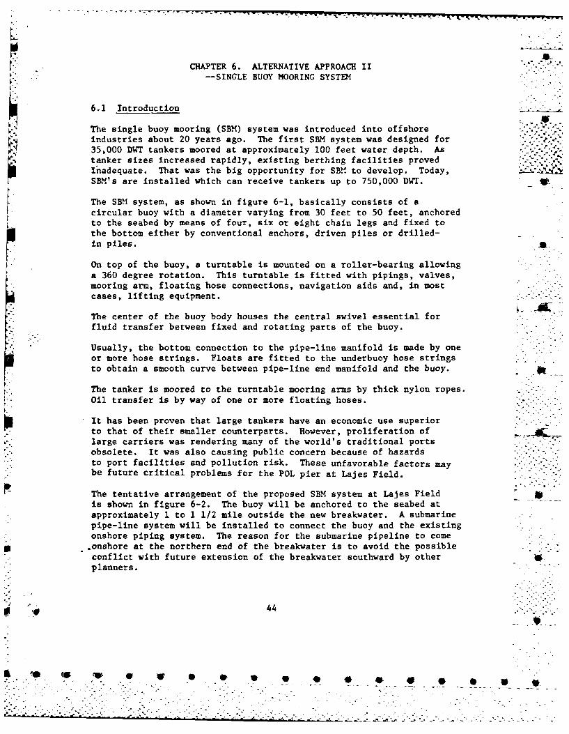
6.1 Introduction
The single buoy mooring (SBM) system was introduced into offshoreindustries about 20 years ago. The first SBM system was designed for35,000 DWT tankers moored at approximately 100 feet water depth. As
tanker sizes increased rapidly, existing berthing facilities provedInadequate. That was the big opportunity for SBM to develop. Today,SBM's are installed which can receive tankers up to 750,000 DWT.
The SBM system, as shown in figure 6-1, basically consists of acircular buoy with a diameter varying from 30 feet to 50 feet, anchoredto the seabed by means of four, six or eight chain legs and fixed tothe bottom either by conventional anchors, driven piles or drilled-in piles.
On top of the buoy, a turntable is mounted on a roller-bearing allowing
a 360 degree rotation. This turntable is fitted with pipings, valves,mooring arm, floating hose connections, navigation aids and, in mostcases, lifting equipment.
The center of the buoy body houses the central swivel essential forfluid transfer between fixed and rotating parts of the buoy.
Usually, the bottom connection to the pipe-line manifold is made by oneor more hose strings. Floats are fitted to the underbuoy hose stringsto obtain a smooth curve between pipe-line end manifold and the buoy.
The tanker is moored to the turntable mooring arms by thick nylon ropes.Oil transfer is by way of one or more floating hoses.
It has been proven that large tankers have an economic use superiorto that of their smaller counterparts. However, proliferation oflarge carriers was rendering many of the world's traditional portsobsolete. It was also causing public concern because of hazardsto port facilities and pollution risk. These unfavorable factors maybe future critical problems for the POL pier at Lajes Field.
The tentative arrangement of the proposed SBM system at Lajes Fieldis shown in figure 6-2. The buoy will be anchored to the seabed atapproximately 1 to 1 1/2 mile outside the new breakwater. A submarinepipe-line system will be installed to connect the buoy and the existingonshore piping system. The reason for the submarine pipeline to come.onshore at the northern end of the breakwater is to avoid the possibleconflict with future extension of the breakwater southward by other_planners.
S44 4
F . -g "i- ". i - . . * * **-.

SALd
C.,
CW,LL&1
LLI,
C, CD
co -A
9L.
0:-
Coo
Ml w
toJ C)
EZ
45
co -c K >>~--* =)-

~~~~~ -07*. ~ -. -
a i
?~4 VI ~ 3>I
1*
a- :
. 46
4-40 06

- Ar -' " -
The proposed Sal system will possess the following distinct features:
e A Deep Water Terminal
As the tanker is moored to the SBM system, the ship will have a stern - -swing radius of 1,500 feet where the water is at least 100 feet deep.The system also provides a 5,000 foot radius of tanker maneuveringarea at a minimum of 60 feet water depth.
e A Safe, Secure "Weathervane-Type" Mooring
, A tanker moored to an SBM terminal is secured with bow lines only and
is free to rotate around a 360-degree arc, like a weathervane, alwaysheading into the wind, sea and current. The tanker and terminal are notsubject to the environmental forces and contact imposed on a tanker . .
rigidly secured to a pier.
e A Flexible Installation
The SBM system can be installed at almost any point off any coastlineor in any navigable water. It can also be relocated should the needarise.
* Reduces or Eliminates Pilotage and Tug Costs
Tugs are not required for berthing vessels to an SBM system. Byeliminating conventional harbor entry and mooring arrangements, tankerhandling costs are reduced.
* Reduces or Eliminates Maintenance Costs on Existing POLPier
The operation of the existing POL pier at Lajes Field will involve
continuous efforts on the maintenance of the fender system, complicated...,.-."- and expensive modifications of the loading platform structure, and
expensive dredging of large amounts of sediment inside the harbor.By installing the SBM system, the maintenance costs on the existing
° POL pier will be reduced considerably.
6.2 SB System Components
6.2.1 Buoy
*The buoy is the core of the SEN system which keeps the whole structureafloat. A field trip was made by LT. Wright (FPO-I) to investigate , "
U ..he condition and availability of the Government owned buoy forpossible use in the SBM system at Lajes Field, Azores. The findingsare:
47
* 1@ ~ ~ * v . ,.*• *.* *,*.
.- " . . .. . *- * . 2 - 2 *- * .- - m ~ -*
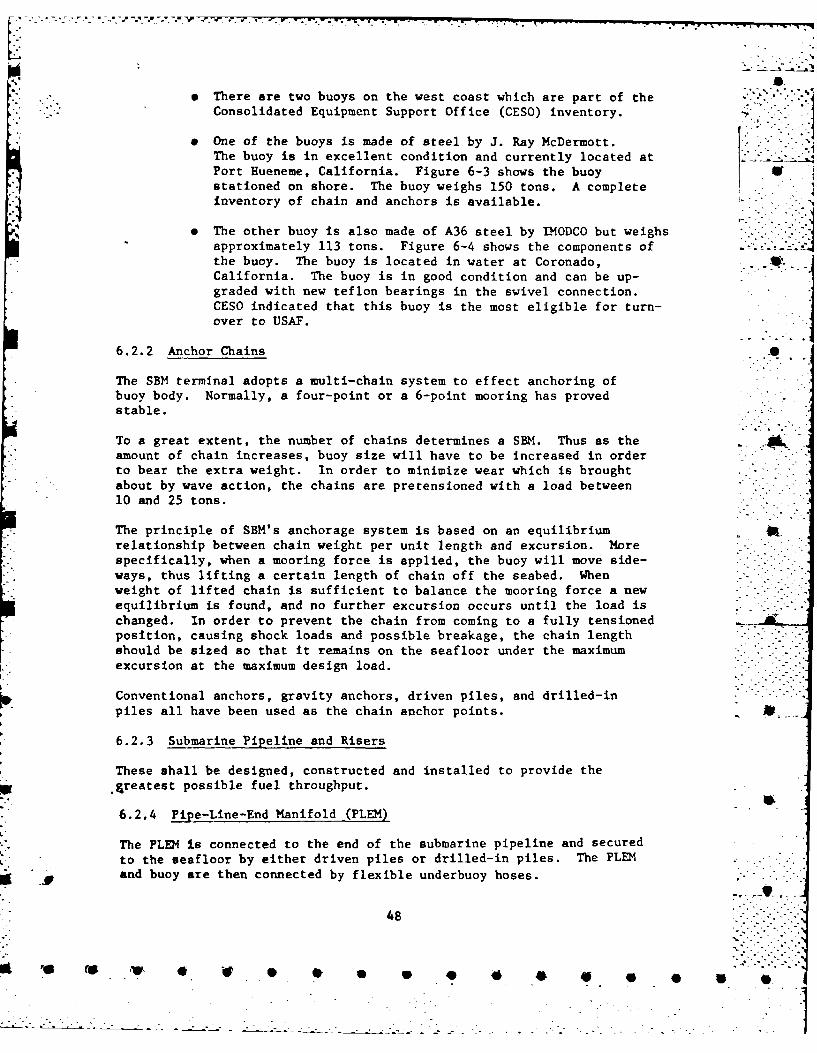
9 There are two buoys on the west coast which are part of theConsolidated Equipment Support Office (CESO) inventory.
* One of the buoys is made of steel by J. Ray McDermott.The buoy is in excellent condition and currently located atPort Hueneme, California. Figure 6-3 shows the buoy
stationed on shore. The buoy weighs 150 tons. A completeinventory of chain and anchors is available.
9 The other buoy is also made of A36 steel by IMODCO but weighsapproximately 113 tons. Figure 6-4 shows the components of .' 2_-4the buoy. The buoy is located in water at Coronado,California. The buoy is in good condition and can be up-graded with new teflon bearings in the swivel connection.CESO indicated that this buoy is the most eligible for turn-
over to USAF.
6.2.2 Anchor Chains S
The SBM terminal adopts a multi-chain system to effect anchoring ofbuoy body. Normally, a four-point or a 6-point mooring has provedstable.
To a great extent, the number of chains determines a SBM. Thus as theamount of chain increases, buoy size will have to be increased in orderto bear the extra weight. In order to minimize wear which is broughtabout by wave action, the chains are pretensioned with a load between10 and 25 tons.
The principle of SBM's anchorage system is based on an equilibriumrelationship between chain weight per unit length and excursion. Morespecifically, when a mooring force is applied, the buoy will move side-ways, thus lifting a certain length of chain off the seabed. Whenweight of lifted chain is sufficient to balance the mooring force a new
equilibrium is found, and no further excursion occurs until the load ischanged. In order to prevent the chain from coming to a fully tensionedposition, causing shock loads and possible breakage, the chain lengthshould be sized so that it remains on the seafloor under the maximumexcursion at the maximum design load.
Conventional anchors, gravity anchors, driven piles, and drilled-inpiles all have been used as the chain anchor points.
6.2.3 Submarine Pipeline and Risers
These shall be designed, constructed and installed to provide the.greatest possible fuel throughput.
6.2.4 Pipe-Line-End Manifold (PLEM)
The PLEM Is connected to the end of the submarine pipeline and secured
to the seafloor by either driven piles or drilled-in piles. The PLEM"g. . and buoy are then connected by flexible underbuoy hoses.
48
re - - ,

-.--. ... ..-- .-. . . .. -I---- -.]..
- .= .i<
, I
.. - - ' " - -" "-; ' :
--4," .
- , - . I. , .
1'A . .._ _ .t..#_. I
-- -.--- k . i -.
I I" ". • i.- $ E.
' " " " ' -' " " , ,, . ' , -. Ii
• -, "-" - - "

-a1£
I IL
* -U-L
K r*-D-
I VZ.*
II
500
Z -'p Y CHAPTER 7. SUMARY AND RECOMENDATIONS ":':- r
7. 1 Summary
The engineering evaluations of the POL pier fender system and loading-_ if
platform structure at Lajes Field, Terceira, Azores are summarized as
e A new fender system is needed to replace the original fendersystem which has deteriorated due ,to operational damage andbiological attack. A fixedwooden pile fender system withcylindrical rubber fenders will improve the energy and forcetransferring function of the POL pier system. However, anew fender system will contribute little to the reinforce-ment of the pier system in accomodating up to 40,000 DWTtanker operation.
e Spalling concrete around the pile caps in the south bentof the loading platform were due to the tensile force inthe piling in excess of the bond force between the pilesurface and the concrete. The pile cap pull-out mechanismrepresents the first stage failure of the platformstructure subjected to a lateral load applied at the concrete ALdeck level. The result of this failure will not causethe structure to collapse. However, the additional loadbeyond the first stage failure load will be transferredto the concrete deck beam and eventually will cause thebeam to fail.
e Cracks in the south bent concrete deck along the longitudinalaxis of the loading platform were caused by the negativemoment acting on the effective T-beam section of the concretedeck beam in the mid-span location. A continuous yeildingof the top reinforcing steel of the concrete deck is thesecond stage failure of the platform structure. The yieldstrength of the concrete T-beam under negative momentis the ultimate strength of the platform structure.
Epoxy or cement grouting of the concrete spalling andcracks will not increase or reinforce the strength of theexisting platform structure. However, the grouting willprevent the deck reinforcing bars and pile cap steel sur-faces from environmental corrosion.
e The existing platform structure does not possess sufficientlateral load resistance capacities for tankers in the40,000 DWT size to operate under normal berthing conditions.To increase the structural strength of the loading platform,the attention shall be in the preventation of the pile cap
.. pull-out mechanism and the reinforcement of the effectiveT-beam section of the concrete deck.
51
V e w . 0 9 , 0 4 * * * " ,
L . o
' One of the alternatives to a structural modification of -
the pier is the construction of three dolphins to divertthe ship berthing energy and force from the loading plat-form. This approach appears to require less initial capitalinvestment. However, the maintenance of a ship approachingchannel and the turning radius inside the harbor will becontinuous expensive operation.
* The Single Buoy Mooring (SBM) system approach is anotheralternative. The SBM system will require the installationof an off-loading buoy and submarine pipe line outsidethe breakwater. The systems requires a relatively highinitial capital investment. However, the convenience oftanker off-loading, accommodation of tankers up to 200,000 DWTsizes, and near trouble free maintenance of the system mayhave a long range benefit as compared with the others.
7.2 Recommendations . .
The recommendations for the future work on the POL pier system are:
(a) Fender System
* Design a new fender system to accomodate T-2 class tankersor C-2 class cargo vessels.
(b) Platform Structure
9 Repair spalling concrete and tension cracks with epoxyor cement grouting.
9 Conduct a feasibility study to consider the operationaland economical aspects of the POL system for tankers up ...to 40,000 DWT size and possibly up to 200,000 DWT sizes.The study shall include, but not be limited to, thefollowing approaches:
--reinforcing the existing platform structure--constructing a loading dolphin system--installing a SBM system
52
' . . * 0' 0 0 Ila 4 00 ** .* ~ ~ 40
-3 REFERENCES
1.De icgn & Construction of Porte & Marine Structures byA. Def. Quinn, 2nd Edition, McGraw-Hill Book Company,
2DEINMNA-Waterfront Operational Facilities,A
3.Foundation Engineering by Peck, Hanson and Thornburn,
JonWiley & Sons, 1953
4. Pannng. esiningandConstructing. -Fixed OfhrPlatforms. API RP 2A, 8th Edition, 1977
5. Reinforced -Concrete Design by C. K.Wang and C.CG. Salmon,International Textbook Company, 1969
6. SEA CUSHION MARINE FENDERS, SCTM-4(5-77),Seaward International, Inc., Virginia, 1977
7. Wood Engineering by C. Curfinkel, Southern ProductsAssociation, 1973
8. Silting and Erosion Control Study. Praia Say. TerceiraIsland. Azores , Preliminary Draft, Department of The Army,New York District, Corps of Engineers, December 1966
9. Jane's Fighting Ships 1975-1976 ,Edited by Capt. J. Moore, RN
1O.Tanker Registra, Compiled and published by H. Clarkson&Co. Ltd, London, England, 1976
11.DESIGN MANUAL- Harborand Coastal Facilities,6NACFAC DM-26, 1968
12.USS Steel-Sheet Piling, ADUSS 25-2369, 7th Printing,U.S. Steel, Pittsburgh, Pennsylvania
Reference-i
0 0l
APPENDIX A
Project Correspondence V
This section contains three messages:
* Request of Assistance on the Structural Evaluation
of the POL Pier (HQ MAC Scott AFB IL/DEN 132030Z Jan 78)
* Tasking Statement from MAC HQ
* Funding Information (1605 ABW Lajes FLD AZ 251430Z
Jan 78)
A-i
.0 4 4 •*

Fl. K~ MAC. SCOTT: AIM IL/DEDI tonXORUEBJHA/GiESNAVFACfl~1 AT-D II~jI 4'
rvCFO RSSAAXJ0'1DR 'MVFACEMCCM ALEXAthDRIK& 7 fCES 1 ~4JDLMAA/165 13U WAES FLD AZOiES/CCYDE. c
.SJ* STUCURA IVESIGTIO O PO PERTLAE PLPE 0A
IN PRAIA )IAM?3R. THlE CON1CRErE DECK AM) STRUC P04L C-RELE. ARZ cEPAL112r... 'THE FENDR SYS-1EM I WUD :S V ERTI CAL %400D PI 17 MS PDJACEN-rj'TO THE CONRTE PIER WHICHQ PRE COWNJALLY SLBJEC17ED TO D-MAGE.2. WE UND)ERSTAND YOU HAVE PERSONNEL 'WITH MARIZ STURALBZ~I~t3 EXPERTISE A0D AIRE UILLIhM 10 PROVIDE US WITH TECICALI
ASISTANCE ON AN ltta1EDIATE BASIS.- ACCORDXN3LY, REQUEST 11LE -41
PAGE 02 RUCtL1AA5551 U NO-AJSA. -' AN OND-SITE V ISIT BY A MIAR & SIRUXMURAL E rZI tZR.
B. A IMNICAL EVJA]JATI0N AMD AINALYSIS 0F THE EXISTI'r3 SITL-. .ATION.I... C. 'A REORT OF.REMNENATIONS SHOW)~IM3 bT1HAT STRJ'U~rAL10DIFICATIM~S MUST_3 BE MADE TO THE PIER 1IN ORDZR TO ACW=0ATE.
FOLI AND CARGO SRIPS OF THE 020) TON SIZE.3. REQUES THE ABOVE TECH1NIC&t ASSISTANCE BE FROVIDED AT THEEARLEST POSSI.31.Z TItiE.l ASSWIN3 YOU CAN FULFILL THE REQUMSSCOKIAINED IN PARA 2 ASVE7', WE ILLu NMGX ARRANr,3EiE1 rS TO HAVE OUPM4R. 'CJEISSERT (AUTO 638-3067/2740) 14EFT WITH1- YOUR PEPRESENrATIVFE01 SITE. YOU S~tOV'JLD 14A.% E ALL TO AMD FRa~ tZF'v^RTAT!ON A.R~r3t-ENTS FOR YOJf? PEPRESE-1ATIVE. AREA CLZAR.4CE 5.<CYJLE) BE O3TA~iiZED
i~USAF FO-REIG14 OERANCZE GUID-E. ON EASE VD) ACW.IMDATIONS tREAVAILABLE..4, IT IS OUR UMESANDIM3 T1{4T CHARGES FOR THL !kZVZ R;EQUESTEI)*SMVICE FOR A PERIOD OF UP TO TWO WEES WILL BE ON A REt UR2SPBLEDSis AIND MiLL. tLT EXCEED $5,VCZ& ACCORDIMGLY, THE16'55 P3'4 AT LAJES WILL -ISSUE A MIILITARY It DZPjRTthE.tiA. PUR~CHASEEQUEST- (MIPR) IN THIS M4QUN WR*EN PLAtr-S ARE FlPR\4.
FOR 1605: WE WILL FURNISH THE3E FUMDS TO YOLR Ht)S.Er13 2 G 3 0 Z JAN '78 DO
0 t651
A -
-. DEPARTMENT OF THE AIR FORCE- HEADQUARTERS 1605t AIR BASE WING (WAC) -~I APO NEW YORK 09406
SDr
S BLC? Praia Port POL Pier V
ML.C/DE
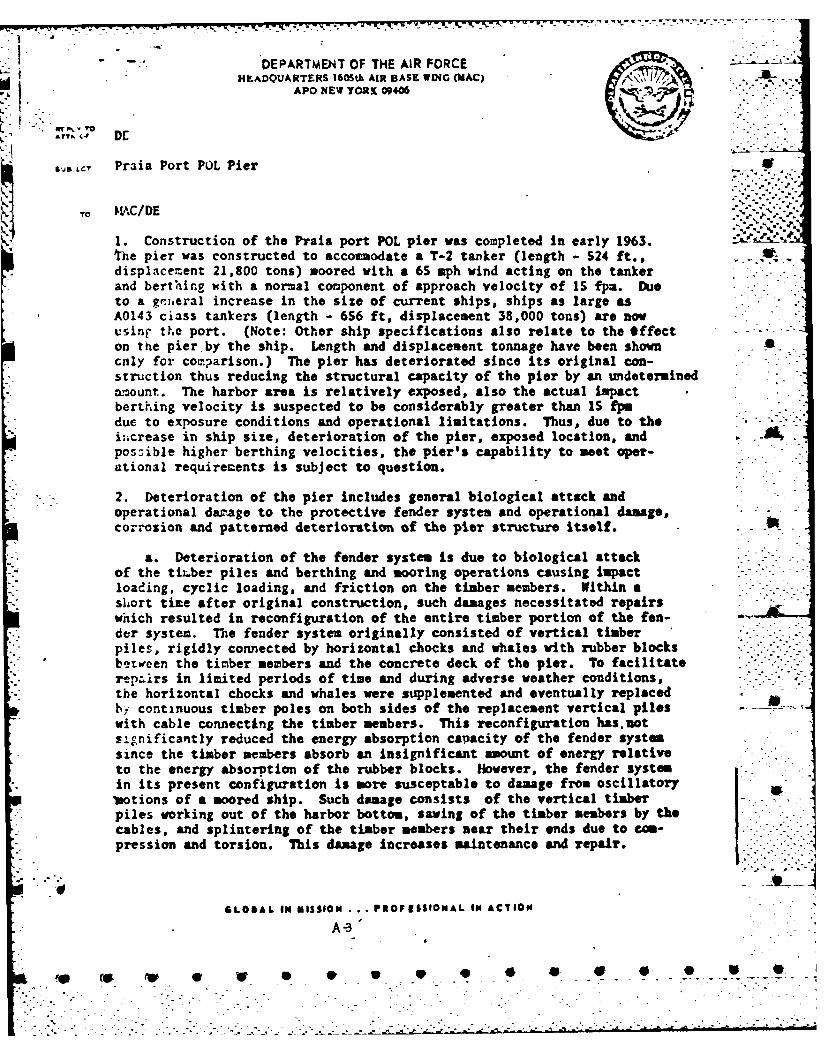
1. Construction of the Praia port POL pier was completed in early 1963. -
The pier was constructed to acco modate a T-2 tanker (length - 524 ft.,displacement 21,800 tons) moored with a 65 mph wind acting on the tankerand berthing with a normal component of approach velocity of IS fpa. Dueto a gr ,eral increase in the size of current ships, ships as large asA0143 ciass tankers (length - 656 ft, displacement 38,000 tons) are nowvsinr the port. (Note: Other ship specifications also relate to the *ffecton the pier by the ship. Length and displacement tonnage have been showncnly for comarison.) The pier has deteriorated since its original con-struction thus reducing the structural capacity of the pier by an undeterminedanmount. The harbor area is relatively exposed, also the actual impactberthing velocity is suspected to be considerably greater than IS fp.due to exposure conditions and operational limitations. Thus, due to thei;,crease in ship size, deterioration of the pier, exposed location, andpossible higher berthing velocities, the pier's capability to meet oper-ational requirecents is subject to question.
2. Deterioration of the pier includes general biological attack and*operational dazage to the protective fender system and operational damage,
corrosion and patterned deterioration of the pier structure itself.
a. Deterioration of the fender system is due to biological attackof the tizber piles and berthing and mooring operations causing impactloading, cyclic loading, and friction on the timber members. Within ashort time after original construction, such damages necessitated repairswhich resulted in reconfiguration of the entire timber portion of the fen-der system. The fender system originally consisted of vertical timberpiles, rigidly connected by horizontal chocks and whales with rubber blocks * . *
between the timber members and the concrete deck of the pier. To facilitate --
repairs in limited periods of time and during adverse weather conditions,the horizontal chocks and whales were supplemented and eventually replacedby continuous timber poles on both sides of the replacement vertical piles - - ___"_
with cable connecting the timber members. This reconfiguration hasunotsignificantly reduced the energy absorption capacity of the fender systemsince the timber members absorb an insignificant amount of energy relativeto the energy absorption of the rubber blocks. However, the fender systemin its present configuration is more susceptable to damage from oscillatoryvotions of a moored ship. Such damage consists of the vertical timberpiles working out of the harbor bottom, sawing of the timber members by thecables, and splintering of the timber members near their ends due to com-pression and torsion. This damage increases maintenance and repair. I.
SLOBAL IN MISSION . .. PROFESSIONAL IN ACTION"
V . " "

b. Deterioration of the pier structure consists of: limited corrosionof the steel piles which support the pier, structural cracks in the concretedeck and concrete beams which have resulted from at least one major accidentalship impact, corrosion of reinforcing in the concrete deck and concrete beamsdue to the cracks and marine atmosphere, and patterned spawling of the concretearound the ship-side center pile of each bent in the south section of the S
loading platform. Each component of this deterioration may have reduced thecapability of the pier to withstand loads imposed by berthing or moored ships.Additionally, the patterned spawling indicates a possible over-stressing ofthe pier, which in view of the increased size of ships utilizing the pier, ishighly probable.
S
3. Repair of the fender system has become a continuous operation. Fifteento forty timber piles are used each year depending on weather conditions andharbor operations. Forty new timber piles arrived at Praia Harbor on 28 Nov 77.Tnsee are being used to replace significantly rotted and damaged timberme bers. Approximately 25 of the piles are needed now and the remainder willbe used as re;uired. Each pile costs $6S0,00. An average of 1250 MH per year Shas been expended each year for the past three years. This equates to theequivalent of a complete fender system (timber portion) replacement on anaverage of every three years.
4. Repair and maintenance to the pier structure now underway consists ofAZ 77-0080, Corrosion Cortrol POL Pier; AZ 77-0079, Replace Floodlights andKLi.ndrails POL Pier; and AZ 76-0031, Install Anode Beds. Projects AZ 76-0031and AZ 77-0079 will prevent corrosion of the supporting steel piles whichwill prevent further structural deterioration of the steel piles.
5. My engineering staff has been tasked to study the possibility of install-ing a new' fender system which will reduce maintenance and increase the energyabsorption capacity of the fender system to a level ¢omensurate with presentoperations. However, an extensive structural analysis of the pier is requiredto determine the capacity of the pier structure. I question whether the pierstructure has the capability to meet present operational requirements evenwith a new, irproved fender system. This evaluation is required imediatelydue to extremely high maintenance costs, the impact on Civil Engineering,and the possibility of major damage occurring to the pier structure or toships. The pier is critical to the U. S. Forces, Azores operations.
6. Additionally, as a matter of information, the Portuguese Government isplanning extensive construction in the Praia Harbor area, including thepossibility during a second phase of construction of extending the pier. - .
Plans indicate initial construction will begin in late 1978, although wehave nothing that would suggest that this date would be met.
7. For the present, we are requesting your support in obtaining engineeringassistance to evaluate the structural capacity of the Praia Port POL Pier,inclusive of its fender system. The evaluation will require expertise in 5marine structural engineering.
A -14
K.]
-
K: -YS. .Me attached photographs, narrative of the photographs, and drawingof the pier further describe the existing conditions.
* RIcHARD T. DRURY, Brig Gen, USAF 3 AtchCommander 1. Narrative of Photographs
2. Photographs (24 ea)3. Drawing 88-01-03, *-
Sheet 19 of 38 w/cowinents
Cy to: MWTNTrGERotterdam, NetherlandsAPO Now York 09159
:0
,.~~A 0.~ 0 ~ * S 9 * 4 . .. . . V if
--_ 'S -. - ..
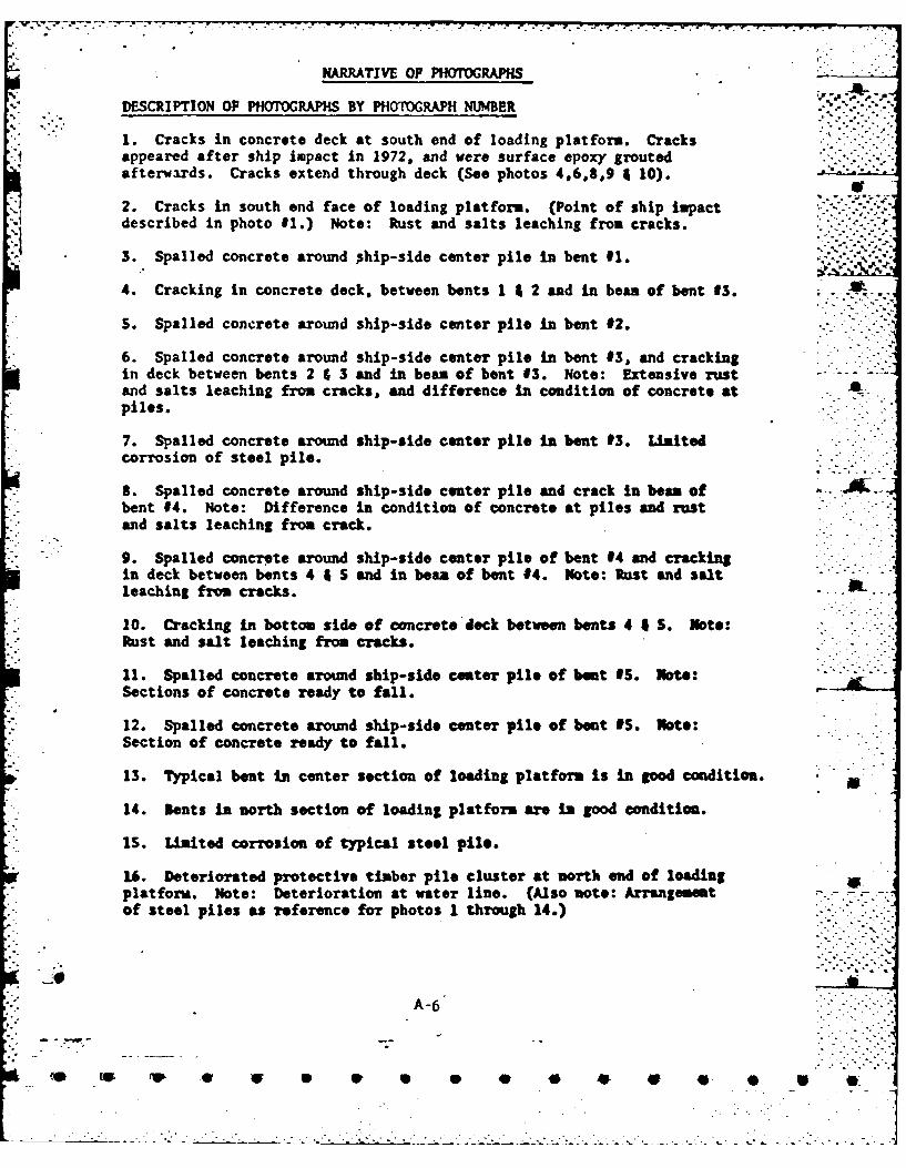
NARRATIVE OP PHOTOGRAPHS
DESCRIPTION OF PHOTOGRAPHS BY PHOTOGRAPH NUMBER
1. Cracks in concrete deck at south end of loading platform. Cracksappeared after ship impact in 1972, and were surface epoxy groutedafterwards. Cracks extend through deck (See photos 4,6,8,9 4 10).
2. Cracks in south end face of loading platform. (Point of ship impactdescribed in photo 91.) Note: Rust and salts leaching from cracks.
3. Spalled concrete around phip-side center pile in bent #I. *.
4. Cracking in concrete deck, between bents 1 4 2 and in bean of bent 03.
S. Spalled concrete around ship-side center pile in bent #2.
6. Spalled concrete around ship-side center pile in bent #3, and cracking .in deck between bents 2 & 3 and in bean of bent #3. Note: Extensive rustand salts leaching frm cracks, and difference in condition of concrete atpiles.
7. Spalled concrete aroud ship-side center pile in bent 3. Liitedcorrosion of steel pile.
S. Spalled concrete around ship-side center pile and crack in bean ofbent #4. Note: Difference in condition of concrete at piles and rustand salts leaching from crack.
9. Spalled concrete around ship-side center pile of bent #4 and crackingin deck between bents 4 A S and in bean of bent #4. Note: Rust and saltleaching from cracks.
10. Cracking in bottom side of concrete deck between bents 4 *S. Note:Rust and salt leaching from cracks.
11. Spalled concrete around ship-side cster pile of bent 9S. Note:Sections of concrete ready to fall.
12. Spalled concrete around ship-side center pile of bent #S. Note:Section of concrete ready to fall.
13. Typical bent in center section of loading platform is in good condition. AD
14. Bents in north section of loading platform are i good condition.
15. Limited corrosion of typical steel pile.
16. Deteriorated protective timber pile cluster at north end of loadingplatform. Note: Deterioration at water line. (Also note: Arrangementof steel piles as reference for photos 1 through 14.)
A-6
* ( W V " S .0 0 * * 4 F * *;2; ." ".-." " " ... - ..' i ? -

.317. Sane as photo #16 -closer view.
18. Deteriorated protective timber pile cluster at south end of loadingplatform. Note: Deterioration at water line. (Also note: Cracking andspalling of concrete described in photos 2 3 $ and arrangement of steelpiles as reference for photos I thorugh 14.)
19. Same as photo #18 -closer view.
20. Present configuration of fender system along loading platform.
21. Same as photo #20 - side view. Note: Cable used for connectingtimber members.
22. Deteriorated and disconnected fender tie back chains used in originalconfiguration of fender system.
23. Sawing of horizontal timber member by cable movement and splintered -
ends of vertical piles.
24. Fenders on south mooring dolphin. Note: Closest face of mooringdolphin is still protected with original construction fender system (thisis tho only remaining portion of the original fender system). . -
IrI
, . +- - q~
~*I. -*.
KcJTES ON PHOGRAPHS:
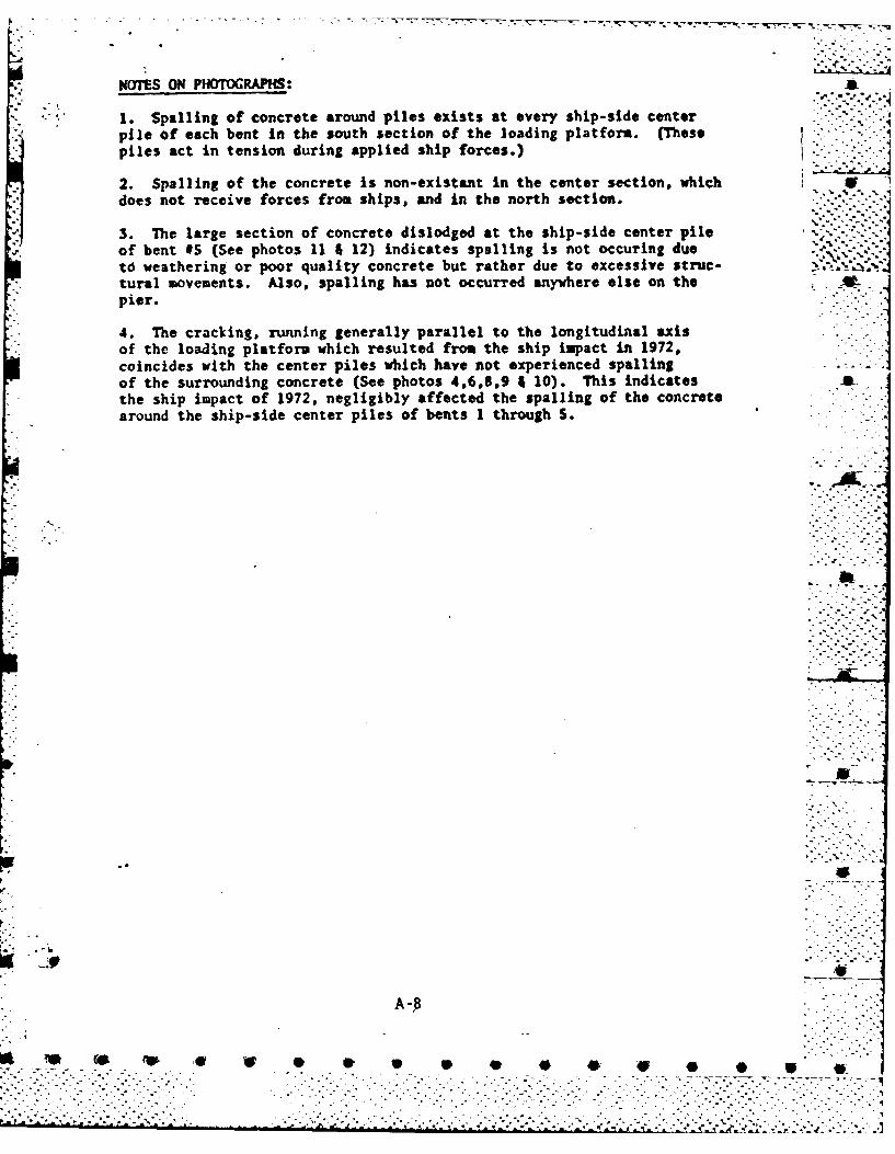
1. Spalling of concrete around piles exists at every ship-side center ~ c-~:pile of each bent In the south section of the loading platform. (Thesepiles act in tension during applied ship forces.)
*2. Spalling of the concrete is non-existant in the center section, which fdoes not receive forces from ships, and in the north sction. ' '
3. The large section of concrete dislodged at the ship-side center pileof bent #S (See photos 11 4 12) indicates spalling is not occuring duet6 weathering or poor quality concrete but rather due to excessive struc- .%4
* tural movements. Also, spalling has not occurred anywhere else on the* pier.
4. The cracking, running generally parallel to the longitudinal axisof the loading platform which resulted from the ship impact in 1972,coincides with the center piles which have not experienced spallingof the surrounding concrete (See photos 4,6,8,9 4 10). This indicatesthe ship impact of 1972, negligibly affected the spalling of the concretearound the ship-side center piles of bents 1 through S.
A -
.~~~~ 4P V~** . . . . . . . . .. ~
-J
CODE ?~ T
SNNGZCHJA017 00 n
RTIUZYLJ'i RUDLAAA6581 025 1525-LUJUt--R'UEBJHA.
R 251430Z JAN 78 CHESDIV (A)-IM1605 AW LAJES FLD AZACR -- ATO RUEBJH,/CESMVFA CEAGC WASH DC iA ",IWO RUCMAA/HQ MAC SCOTT AFB IL/ACBC
RJLSSAWCOYDR VFACENGN M ALEXANDRIA VARTCBSAA/CINOLANT NDRVA/J413
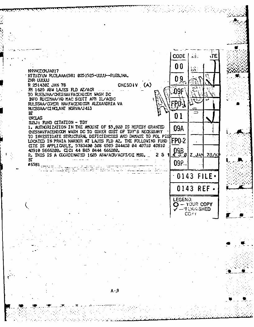
WCLAS01a.rJ: RND CITATION - TDY1. AUTHORIZATION IN THE AMt1CNT OF" $5,00 IS IERE'Y GRANTED 9A*OiEVFACENooI WASH DC TO OER OST OF TDYrS iSS Y- - 0TO INVESTIGATE STRUCnRAL DEFICIENCIES AND DAWL.GE TO POL PI --
LOCATED IN PRAIA HARBOR AT LAJES FLD AZ. THE FOLLOWII FUNi FPO-2CITE IS APPLICABLE, 578340 3 6505 24442Z 04 40710 40810403910 S66620., CIC: 44 865 0444 666200. .V-R2. THIS IS A OORDINATED 1605 A3W/ACR/ACFT/DE M. 2 5 1 -Zj- Z.JA. / r
i .. . .... ...... . ..- ;- -.-: 0--- ..: - * --
.0143 FILE,
0143 REF•LEGEND:
, O-- YOUR COPYV -- U SHED
A -'.
A-"""' "-
I e t _ .. . - -- - -- --- -- - -. -- +
|:~~~~~~~~~~~~~~~~~. .. . .. . . . . .......... / ::i:-. :. _ :.... . -.- ,.,-..-_....,.............
-" -;-, -.-."-
APPENDIX B
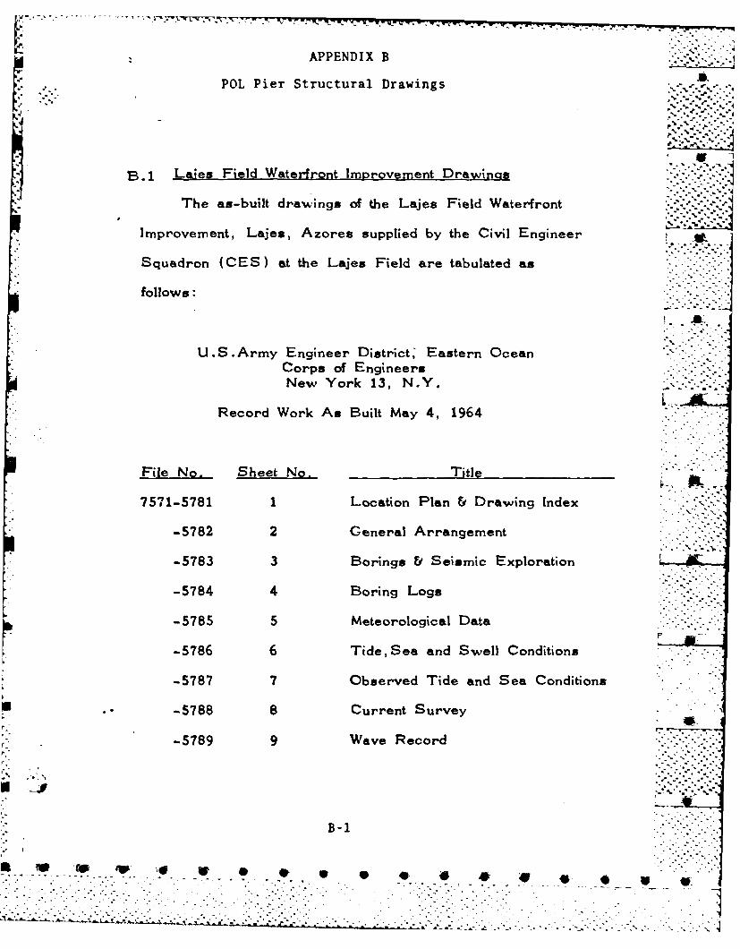
POL Pier Structural Drawings
B1 Lajes Field Waterfront Improvement Drawings
The as-built drawings of the Lajes Field Water-front
Improvement, Lajes, Azores supplied by the Civil Engineer
Squadron (CES) at the Lajes Field are tabulated as
follows:
U.S.Arny Engineer District' Eastern OceanCorps of EngineersNew York 13, N. Y.
Record Work As Built May 4, 1964
File No. Sheet No. Title
7571-5781 1 Location Plan &Drawing Index
-5782 2 General Arrangement
\ ; -.%.-
-5783 3 Borings & Seismic Exploration
-5784 4 Boring Logs
-5785 5 Meteorological Data
-5786 6 Tide, Sea and Swell Conditions
-5787 7 Observed Tide and Sea Conditions
-5788 8 Current Survey
-5789 9 Wave Record
• " , -J..-,
B-1
Ne Yok 3 NY""0 ,q .pReodWokA uitM4, 494-"' '

Ae.
File No. Sheet No. Title
7571-5790 10 Refraction Diagrams
-5791 11 Refraction and Diffraction Diagrams
• ,° -° .o --- a%
-5799 19 POL Pier-General Arrangement
-5800 20 POL Pier-Bridges & Walkways
-5801 21 POL Pier-Pump House & Foundation .
-5802 22 POL Pier-Loading Platform -.
-5803 23 POL Pier-Concrete Details _
-5804 24 POL Pier-Mooring Dolphins Nos.1&2
-5805 25 POL Pier-Mooring Dolphins Nos.3&4and Walkway Supports
F -5806 26 POL Pier-Miscellaneous Details
B -2
W 4' * 4 -0 0 9

B.2 POL Pier Modification Drawn
CES of the Lajes Field supplied the following
drawing relative to the POL Pier modification*
U.S.Arny Engineer District, New YorkCorps of EngineersNew York 3, N.Y.
30 June 1966
No Sheet No.Til
-- -- Proposed Modification to POL Pier
B-3
~. ( ~w w . . . . * * * 4F
APPENDIX C
Field Investigation Briefing
The notes documented herein are those presented to
the officers at the command level in the Lajes Field on -
3 February 1978.
C-1-
qr 0 0 40

7-,m
POL Pier Field Investigation Briefing
Place: Lajes Field
Time: 0900 (Local Time) -s. .
Date: 3 Feb 1978 :-Attendant:
Base Vice Commander Col. Bobby Massingill (AF)Head Engineering &Design Lt. Col. Larry EnglandDeputy Lt. Col. Al Meyers
Lt. Scott Fehseke
TTU Commander Lt. Col. John Telfer (Army)Deputy Lt. Col. Walls
J-4 Lt. Col. BentleyLCDR.Allen Hill (Navy)
LG Lt. Col. Rodenheiser
MAC HQ Les Weissert
FPO-1 LT. James WrightC. Chern
C-2

-',,,'V X-X 4-- 1-.
LAJES FIELD
POL PIER INVESTIGATION
Ocean Engineering & Construction Project OfficeChesapeake Division
Naval Facilities Engineering CommandWashington, D.C. 20374
2 February 1978
C-3
0E 4W is # 0 w
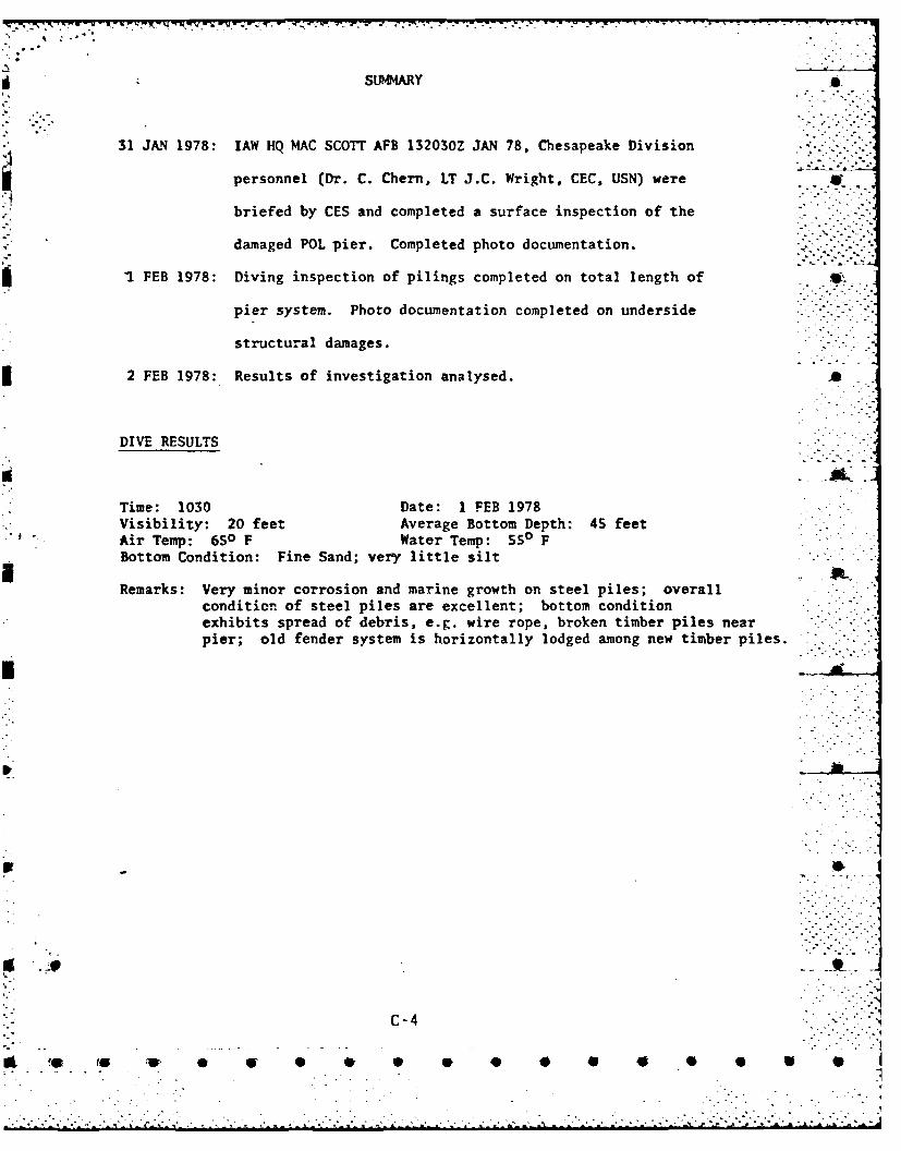
SUMMARY
31 JAN 1978: lAW HQ MAC SCOTT AFB 132030Z JAN 78, Chesapeake Division
personnel (Dr. C. Chern, LT J.C. Wright, CEC, USN) were ,
briefed by CES and completed a surface inspection of the
damaged POL pier. Completed photo documentation. ..-.
1 FEB 1978: Diving inspection of pilings completed on total length of
pier system. Photo documentation completed on underside
structural damages.
2 FEB 1978: Results of investigation analysed. ja
DIVE RESULTS
Time: 1030 Date: 1 FEB 1978Visibility: 20 feet Average Bottom Depth: 45 feetAir Temp: 650 F Water Temp: 50O FBottom Condition: Fine Sand; very little silt
Remarks: Very minor corrosion and marine growth on steel piles; overallconditicn of steel piles are excellent; bottom conditionexhibits spread of debris, e.g. wire rope, broken timber piles nearpier; old fender system is horizontally lodged among new timber piles.
.- .
C-4
to la- e or s' 9 0 4 0 40 40 0 0 0 0
.. . . . . . . . . . . . . . . . . . . . . . . . . . .

PROBIBI STAIMENT LConcrete pile cap on many interior steel piles has broken away
- due to horizontal loads applied in excess of design loads.
*Wood pile fendering system is easily damaged and components arebeing replaced at highly uneconomical frequencies.
C-5
'S~1 40 W- S V S S* .
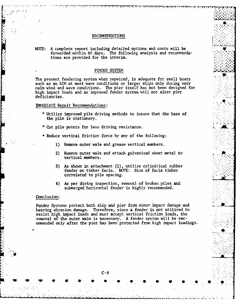
.... .- - .-v .. % .- "r.
"*~ -,fJ,
RECCI NENDATIONS
NOTE: A complete report including detailed options and costs will beforwarded within 60 days. The following analysis and recommenda-tions are provided for the interim.
FENDER SYSTEM '.-"-"
The present fendering system when repaired, is adequate for small boatssuch as an LD1 at most wave conditions or larger ships only during verycalm wind and wave conditions. The pier itself has not been designed forhigh impact loads and an improved fender system will not alter pierdeficiencies.
DVEDIATE Repair Reconmendations:
* Utilize improved pile driving methods to insure that the base of
the pile is stationary.
Cut pile points for less driving resistance.
-Reduce vertical friction force by any of the following:
1) Remove outer wale and grease vertical members.
2) Remove outer wale and attach galvanized sheet metal to "vertical members.
3) As shown in attachment (1), utilize cylindrical rubberfender on timber facia. NOTE: Size of facia timbercorrelated to pile spacing.
4) As per diving inspection, removal of broken piles andsubmerged horizontal fender is highly recommended.
Conclusion:
Fender Systems protect both ship and pier from minor impact damage and ..heaving abrasion damage. Therefore, since a fender is not utilized toresist high impact loads and must accept vertical friction loads, theremoval of the outer wale is necessary. A fender system will be rec-ommended only after the pier has been protected from high impact loadings.
C-6
'@- -, -.0 P .-

...* PIER MODIFICATIONS
Attachment (2) - Docking for T-2 and T-5 Class Tankersfe
* Existing pier utilized for small craft only. . i• Construction of two or three dolphins for use when docking
T-2 class or T-5 class tankers.
* Dolphins provide protection to the pier from any directhorizontal loads. Typical dolphin systems are shown inattachments (3) and (4).
Construction of dolphins would make the pier inaccessible for POL or Icargo transfer for an estimated 30 to 60 days. Therefore, a temporarysubmarine pipeline can be constructed as shown in Attachment (5) for
POL transfer.
* Some dredging may be required.
Attachment (6) - POL Transfer Utilizing SHM System
* Single Buoy Mooring (S"{) system is alternative to dolphinconstruction.
4, POL transfer from tankers up to 200,000 MT.
* Cost of new SEM system is estimated at $10 million.
* Existing POL pier utilized for small draft only.
NOTE: A third option consists of strengthing the existing POL pier torsist heavy impact loads. Costs would include structural modifications,heavy fendering system and dredging. This is not a recmmended approachat this time.
C-7
.-.9- 0 4 =

rOr
rLA
h..D Js~u~z0 e
2 AitA
X 0
UZ ~ - S S
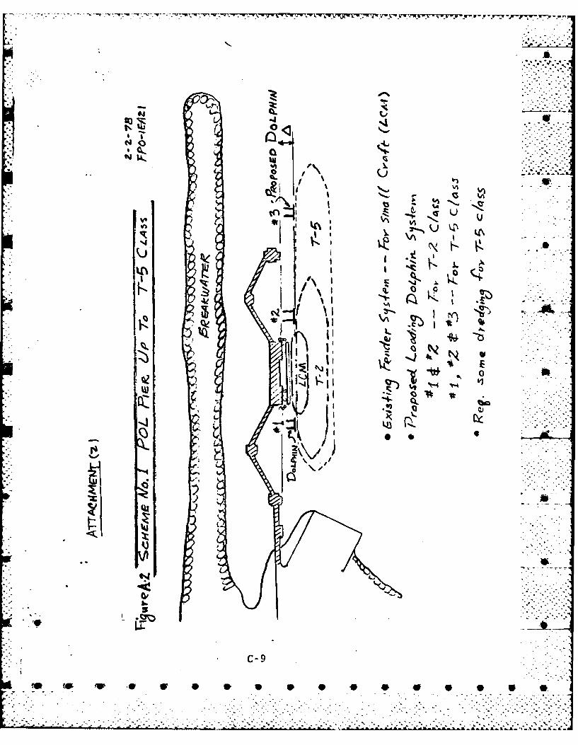
.4 "
-1
• , , ,aS
:'I.: -- : .
STI
"- . C-9
0 . 4P .p .9 -
.. . . .. , . . - .:.:. .: .: : .' , .. :-. .... ::- % 4,- -L . - . .. , : . - . . .. . . - .- . . . .---.- . . ." " •° ""-_L . '., .. , "-,,"_ "-2 .. '.:',- .. ". "."-'-':-""-::-" '---'-''.'- -'¢S.'_..-'-''---.' '.; ~r'. c. L .E .';. z .Z..Z "X £
".,,. .o
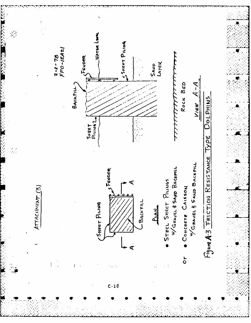
p - ww- ~ - . - -. . -T -. .
lu -S
2 w
ci-a
wI 2>
400
0
> U)
J V
MCj1('

w 7-'. ' .i
cc C
2 L LG I *
( 2 .~in
CE w
IL) -p2
0 2y
-11
0 40 4

oO~coITjt~c 2 l
- (0ZS
T''U
IV-
I- ii
. C-12

qt*
ViV
Ic-
SIMI
*-. h A
APPENDIX D
PLPier Structural Evaluation
Th is section compiles the engineering calculations on6
the structural components related to the ultimate strength of
.the existing pier structure and the operating limitations of the
proposed new fender system.
D-1
D. 1 Pile Cap Pull-Out Strength
In the absence of reliable data on the bond stress between
the pile surface and the concrete cap, the allowable stress of
20 psi from reference 4 is used to compute the pile allowable
pull-out force. The ultimate pull-out force is then obtained by
multiplying a factor of safety of 2.0 to the allowable pull-out
force. It is noted that the factor of safety of 2.0 is selectedAL
by common practice under such circumstance (Ref .4).
D- 2
if@ to~ 1W 4P. * * * *
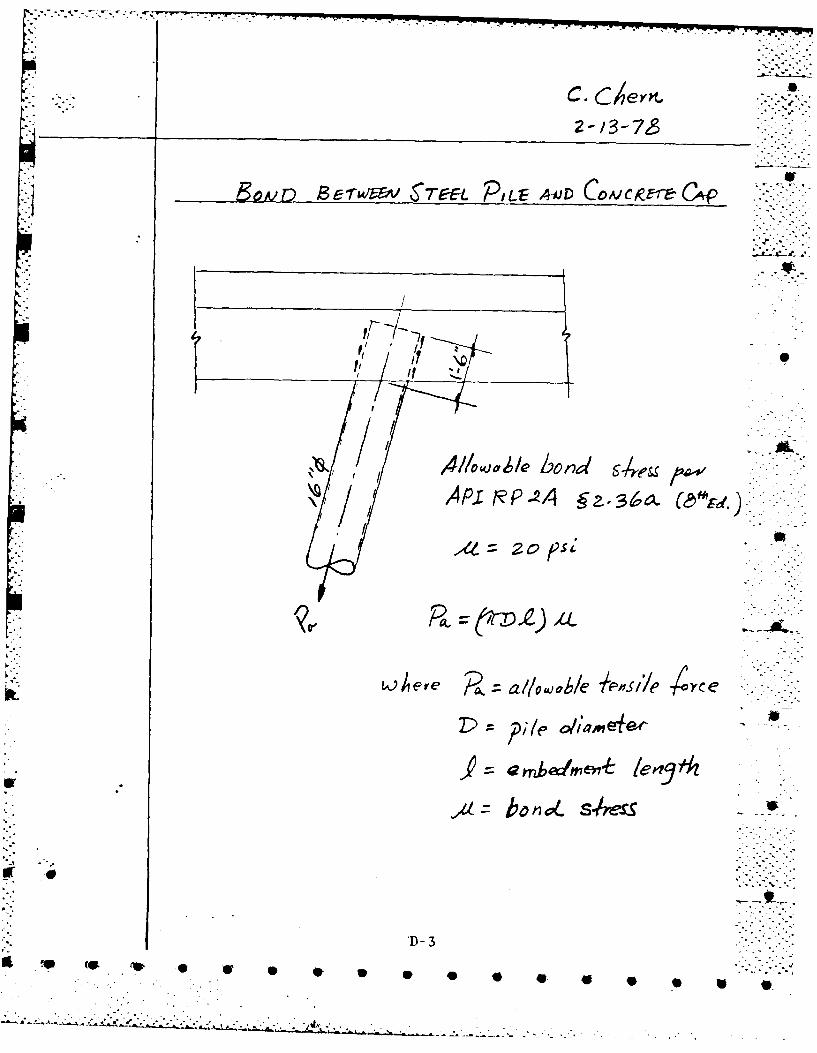
2 -13-7
govp BwFA 7EEL PILE AMiD CDVC-kEre~ CW#
Ar NP-2A gz.36a.(9~.
LOhere all c/owaol/e r&'sslie YoC e
dboni VL s/S-b
'D- 3
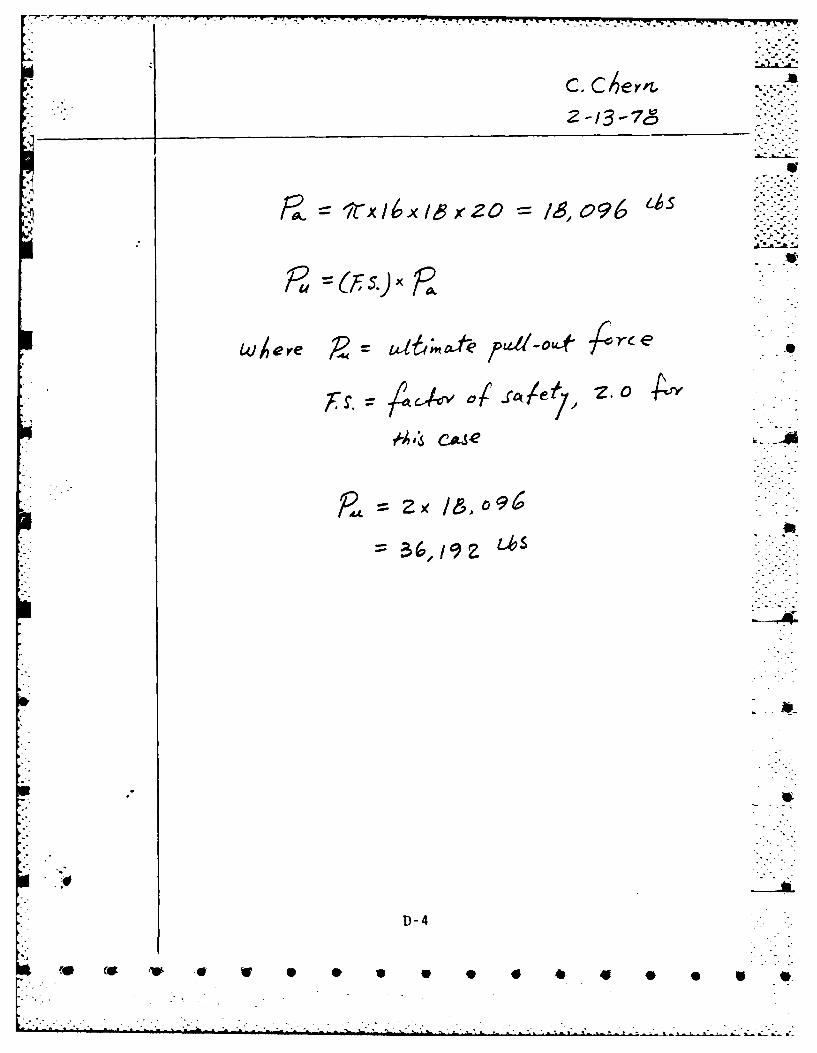
SIrx16x1,exzo 16,096LS~o~ev ,~ tbnt2tE 1 pb ubt 7Dr-
r/A~fvoftie?;iZ.O0 4Y
D -4
C.'V F.. - S 4.0"4 * 0.

RO-RI65 765 LWES FIELD AZORES POL PIER FIELD INVESTIOATIONS AND 2
RECONNENDATIONS(U) NAVAL FACILITIES ENGINEERING COMM ANDNASNINGTON DC CHESAPEAKE.. C CHERN ET AL. MR 78
INCLSSIFIED CHES N AVF ACFP - FPO-±-?B6FG1/I2 UL
.hohERhh6hh
m~h~mmhmu

- -
13.2.
(
/
11.
L IJ -
1111L2 .4
11'1-1-L6
MICROCOPY RF~flIUTIflN Tf-t CHART
I .
...
I
.1
*.~.'S. ..

.° ,,"A. % , _--
D.2 Pile Foundation Pull-out Strength
The ultimate pull-out strength of the 16" 0 steel pipe pile
in sand is computed in this section. In the computations, it is
assumed that the pile pull-out resistance is contributed solely _______-
from the friction between the pile embeded surface and the
neighboring sand.
Clean sand characteristics are used in the computations.
Pile penetration is 40 feet below mud-line.
L-- W.' ,. 4.i:
D-5
i, S S , V * . * o * * * * * ","4

c cerkt
P/LE C44ITY r-oI AxIAL. PLOI LA 4- 'i
AJ RrRPPA ?.zA 15 t4n1
wAere u~, 6uJ -o 1e D; e pa tu1 ce2 drae - a
As~ side 5,,,- face area /;/,/
Lihere Ik t ~,e4o p/e./ ?tI
or 4n9 e o$'SvOl/ /ic 1 ,/ wd
de yree., .30* -14 ceoSp
D-6
IU to 'Wp S 40 4 4* 0 9 W
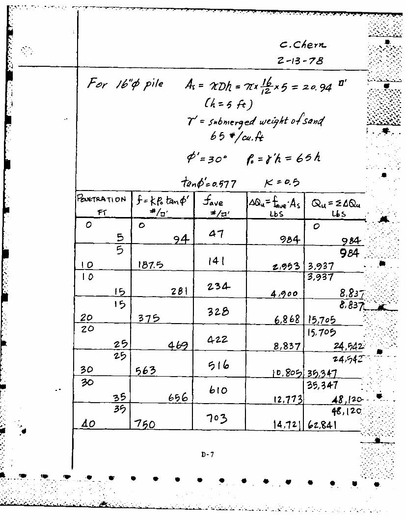
9001 -- o-677
94 9 S4.
15 5,0
___1__17
48,1-2o7 __ __ _
Ao I) 0
5. 14
____ ___Z8I .'-7dhF N3"2~
-. .-.-.. '. .- './'.'.-
D. 3 POL Pier Structural Strenith
The structural component failures and the corresponding I
lateral load resisting capacities of the pier are evaluated in
this section. The possible structural component failures are: 7
e pile cap pull-out
pile foundation pull-out
e concrete frame beam failure by tension yielding.
The lateral load causing the pile cap pull-out is found
to be the lowest failure load of the pier structure (27 kips
per loading frame). Subsequent increase in the lateral load
application will cause the concrete frame beam to fail at the
mid-span location by tension yielding of the top surface
reinforcing bars. The ultimate lateral load resistance per
frame is approximately at 39 kips.
J
D-8
".- - ' -..A 7-...-....-. -- -.
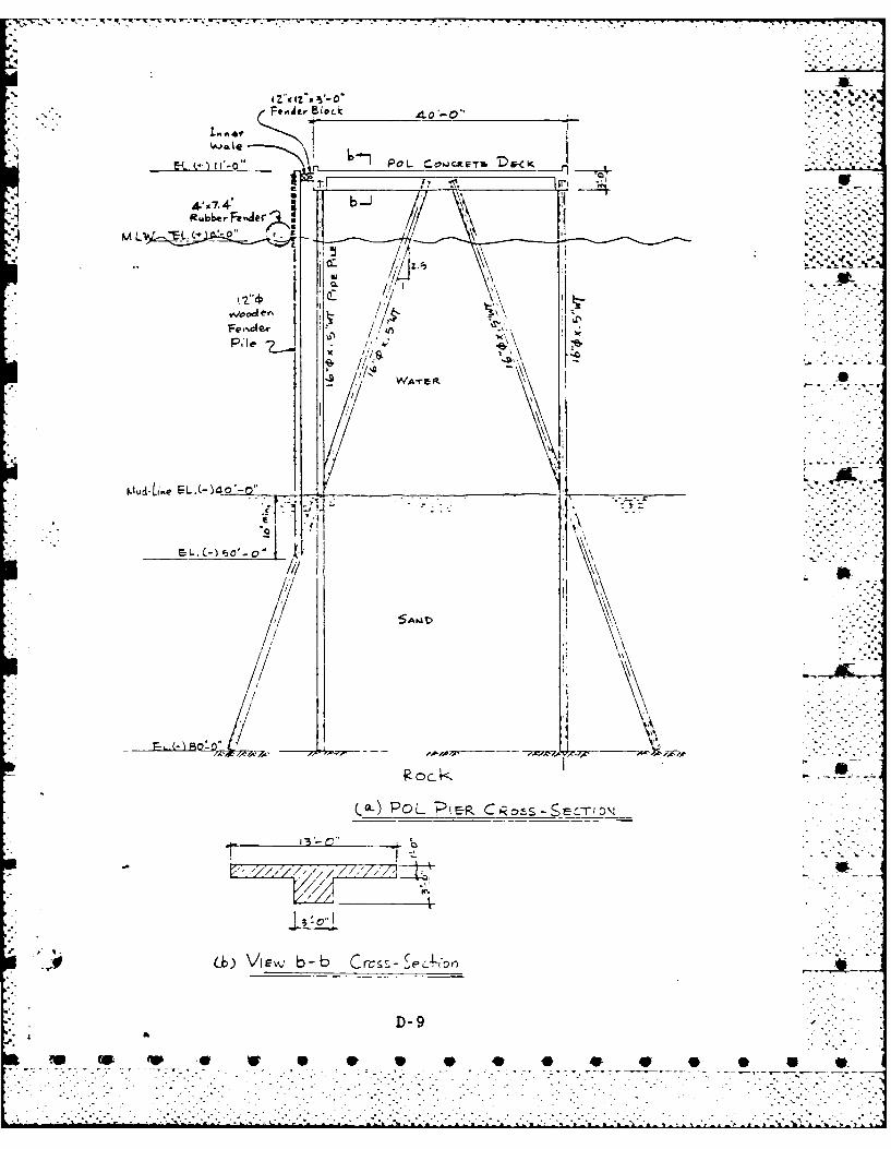
40,0
t.)I*- o CCW'JCLT. 'D&.<K .. .-
WA e f
oua-L~ meI-A-4
(a-) R ?OL 'Pi- CRs -cLrio,
D-9
0F W
/1
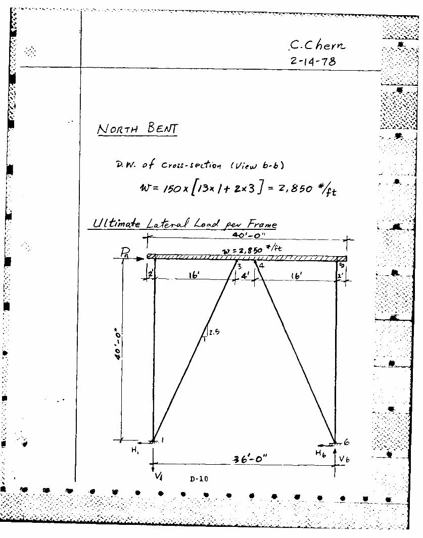
_______ _2-i1-78
/VVZ.4BEI
150. x -fZx
*4 t
Za&,- romV .%01.. A
-S.~P IO?-- Be4Tr /vxx. *
~~).W4 IrvOS-P'~I L'eu.
V ,Oc/~/~ZcT28o4
U~bne Af-i~JL.'~ ~e~ Frae 6
V D-10
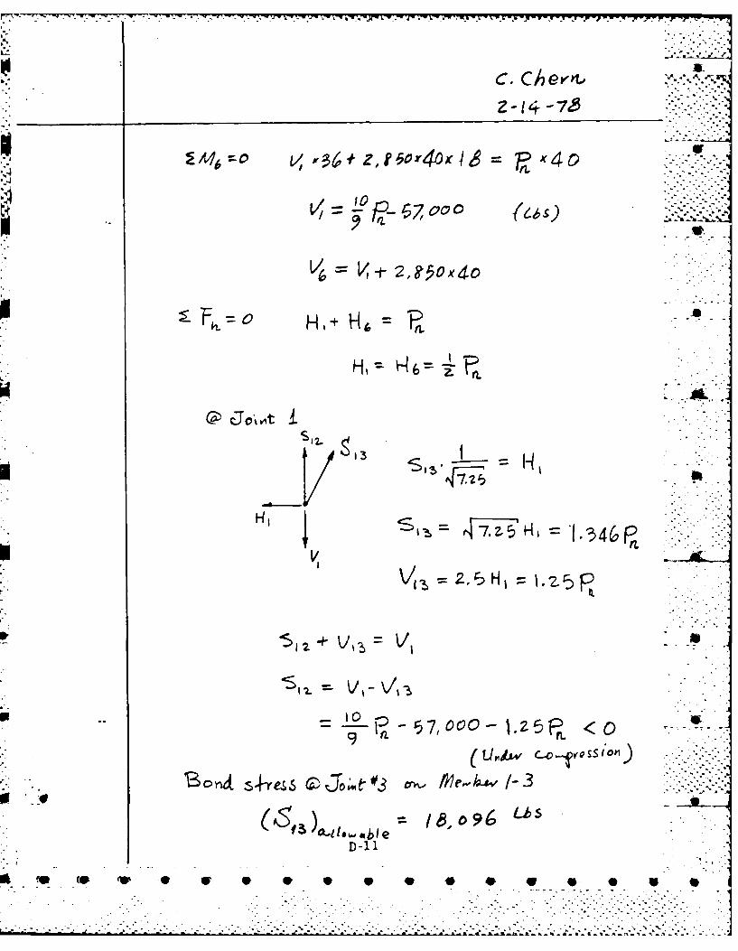
C. Che-' SINZ.... ,7,
474I
9.
Cjo/i3 1-3
D-11
wJ F v oos (fa """"
-, . . .* .. . -- . -...- - ..
S-. -* ----~~z" -. --- 2,-. - . . . . .. . . . . . . . . . . . . . . . . . . .. ..
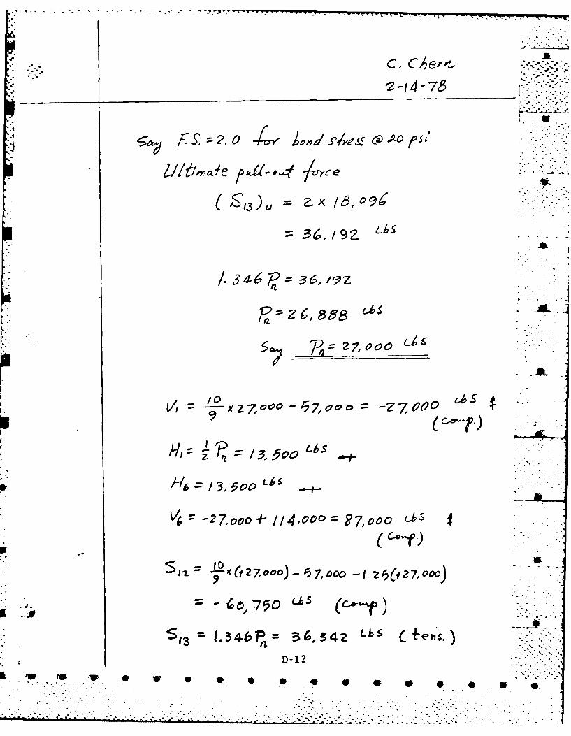
' " 4*2 -14 --73
f2.O A~ 4,6 A p"
.A
/. 346 = 36,9z
P121
=6 2-7,oo) , o 7, o o o s
- °x .-7 oo 7,o- 7.,
LLbs
H = /3.0c' Ls
V: --- 7',ooo+./114,oooZ T7, ooo LI's %
$,D # Ctz,o-Jt 7,000 -I z &2,ooo) ... -
D-12
I ' "" p '-u - *"'"' * *'- - . -
... ........ -.... .. ..... . •. -.. • ..... - •- ..-- -'- ' " ' " " m""" "" ' ' % ""* "." " " "" " "-"" " - """ "" " '".*

~' 2-14-76
t -7, =o 34,,740b
260 C.0
97,00oo
27,000* 42 5 /t
s (4-)Tension
13100 N04e- Ie4Ctz;-toyces 1s5X
D-13
'S~~ 4DW *

.. ....A
C. C/er.. .
4--'- 0"
6 0-..- ..............
Ii Vt. \ .
D/-.
D-14

t4-723
V, 36+ ,8504006& f.,4O-9 --. Ps.5::7, :
"V i14 So x 4--.-..o$I:L =V'I
VI= --s- a, £5o x4.o <--.:
_ Ps S 7,l oO+ /14,0009
= -9 Ps-I-"s 7 oo .P:- :7::-:
5 V
w . %
P.5.
,. I)D-15

40"'" . ~~C e,,4'-"...
PS. Z, 0- .t
*4I
r-10 + s .ia-,4 -700,, 7~ -r-
9::::= .-Z o 4,oo o ;,-Lbs)
D- 16
-. D -1 6

.19
'-- ~~ ~6 tz 39 P - 75 7:::--::-.
15R 6-77 5
to 3,7 Lbs
-7 -7,0 0 (7,44
9 Z'
4 -P Ps 4=0,0 (- - ,
~~ #x~~D7O7,~O 744Lb-M L
°|!
' 0ie3,ePI b 3cs.
r "
-:-.."..-I.:8-. , tg. = . -9 P -.. - -- ,. o :.,. .

C- 7-10 iA/ I/A/ D VF&6A Tivg MoMFE-T
V-to
-JewA~~aiv~ o' gheslmce
FD- 18
F. 'VA p-I x~ j 50 ,
-Ff C ..
Fc rlA -S
. L 3 .L Id-
...... ...... ......
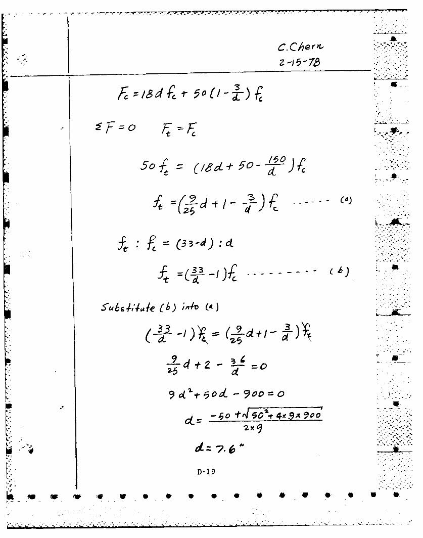
C.C Cer&--1, - 76 ..
5Or, (id?50 4x-9 9
=(3:ct:
D--9
91--0'--90L.O
50 L- -o f5o4 """"
.... . :::I LD-1-9".%a'

:1 ~C.C/e?
33 - / 0-
77.6
~~OX360O, gooo
7a.6
6*Z*
Al: o~oo ,g o
(fx v*X D-70 -5 6M /c 0
r.F x

• C.C,-ei..i.-. 1 1
C. CA r,"' ""
" __Z-15-7& "" .7"""
,, p, ,.-...-0
,4z4 ( o -46ooo0
P.5b
- A ..-
$4 ." i~,i~x .3,3 5"7 - -
99--.- -- --7 -:'
5oa=2-5X369,3-57- -79 o .
-- /- " - s ( . . .).:.:< :: :D - 2-"-1 .'-
0 0 0 4P V .0 o1 W

(-t) 7ThnSiOP '-
D-22
_ .. ~. r * u * * * ** .
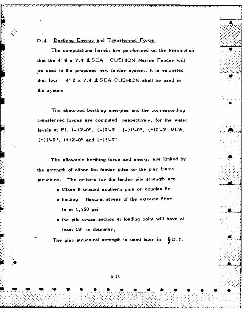
N.
*2 ". -. '.-..-.'.. .
D.4 Berthing Energy and Transferred Force
The computations herein are pe rformed on the assumption
that the 4' 0 x 7.4' LSEA CUSHION Marine Fender will
be used in the proposed new fender system. It is esfimatedeV
that four 4 0 x 7.4 SEA CUSHION shall be used in
the system
The absorbed berthing energies and the corresponding
transferred forces are computed, respectively, for the water
levels at EL.(-)31-0", (-)2'-01, (-)1'-0", (+)0'-0" MLW,
(+)1'-0", (+)2'-0" and (+)3'-0".
The allowable berthing force and energy are limited by
the strength of either the fender piles or the pier frame
structure. The criteria for the fender pile strength are:
e Class II treated southern pine or douglas fir
o limiting flexural stress of the extreme fiber
is at 1,750 psi _
e the pile cross section at loading point will have at
least 18" in diameter.
The pier structural strength is used later in D.7. -
D-23
qw "w qP .W 0 is V O * 4 - -
...."............ ....". ." .'.-"" ."- "% -'j.s"°. .. ." " . . ',' s" -'-"s% -" ".. . .. "-"-".". "." '."." -
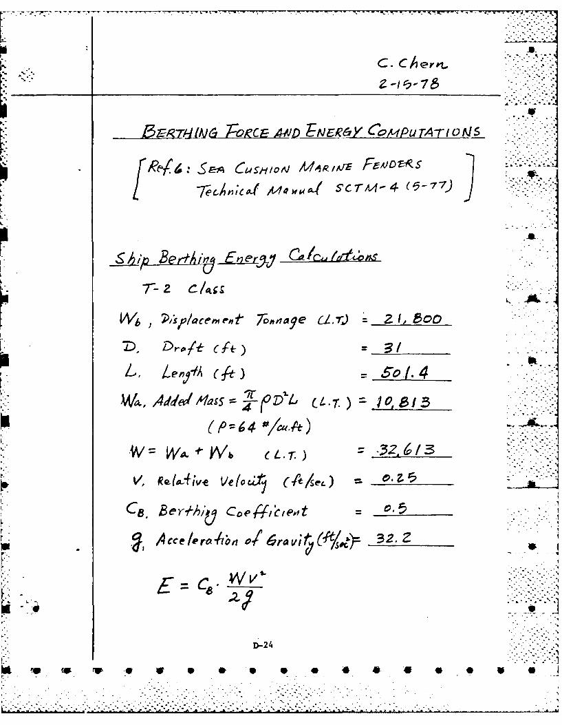
C. CAer.?.
A.
WaK Aw0d ,tqa-( sc l-4(5
Vca-
A~ cc e/le r n vi*r ;t 2
E~CWv
D-24
qp w

* C ,
J'It,- /47-
36 "- 4
Use Sec.s (4~~AA -"-, 7 7,)Ca46,OC~l4~
En eW~ 4isorpi-z = s
Aead4 Force =
D -25
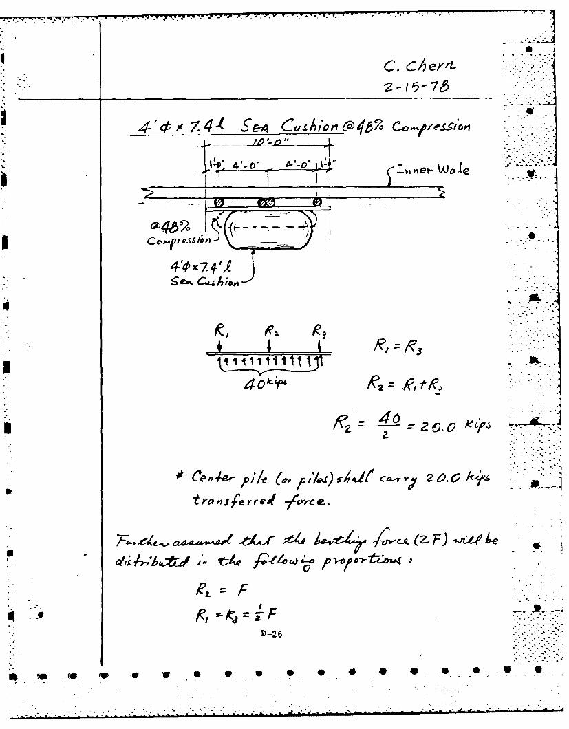
TVV
j 11 4- -00 l'
'4 -
k,9
* /?= -~~ = 0.0 ~pk
treanserred 7 4-rrce.
- ~ a44~~~ ~e~;e4 jo-1A 4 -cx (2- 4)~t i
c~l; A'iAtd'A~4f/e4~ )v~de 4
D-26
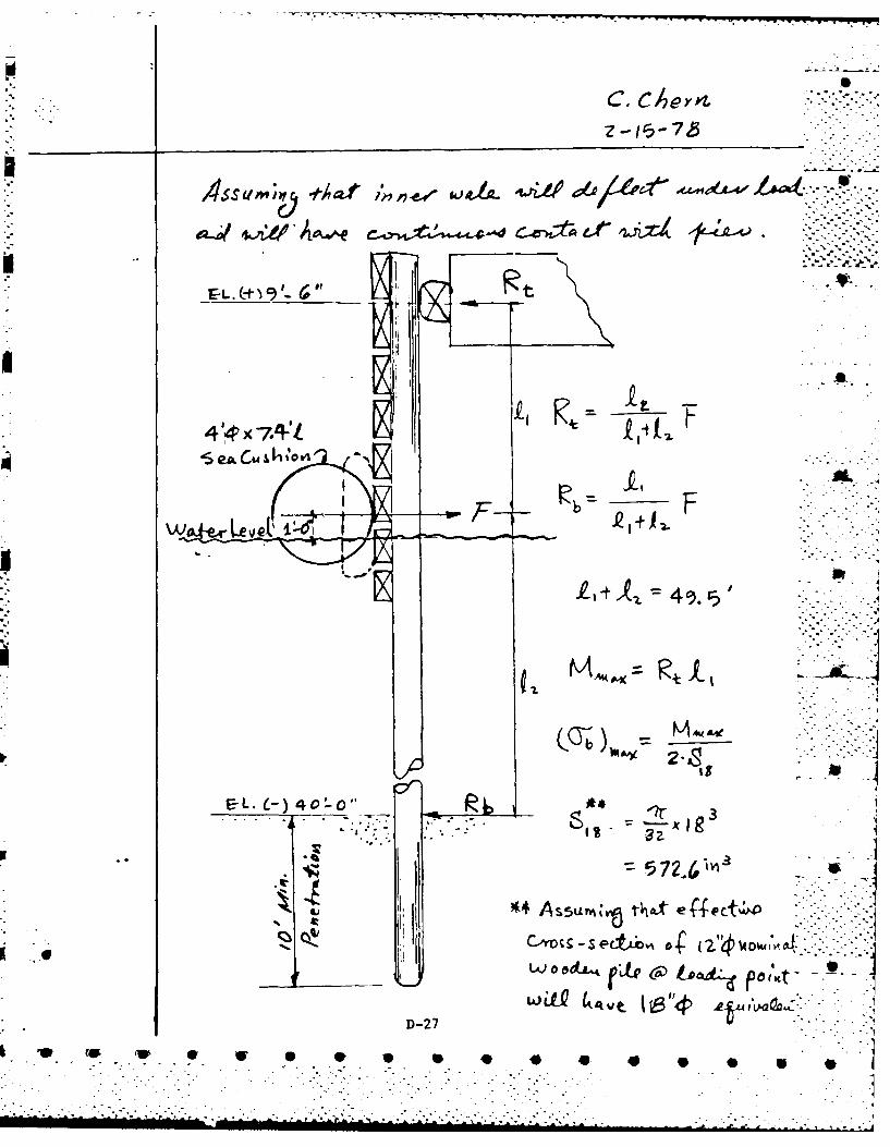
C. C/~er4
4sImI -*.--t to,
AL j
E-L.Li L-) 4c).0 57~
.e ~~~~C'-eti4(ou
L&)LQ &'~e~ S"#k~A~L19.
D-27
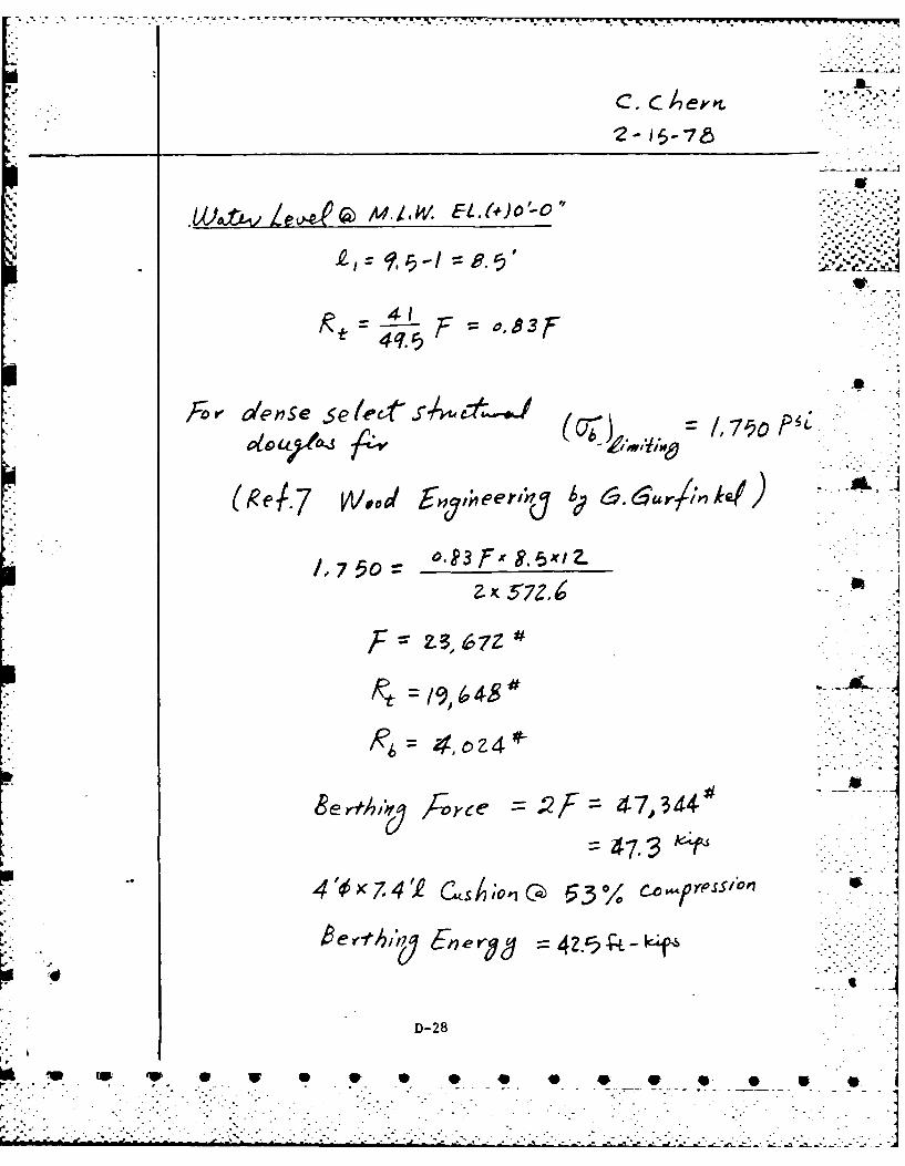
C. bb'.
tv2-~ eS7
For dlense selefskata-
F2, 4 7,67Z4
4O74T asA;oG 5301 fc4pt7S P
e rfhl 7 gne r 42.Cf. -L-k~f4
D-28a

,.~C c.-o
.. Z - I . -L 7 8 :-":"-"-
1-5 -765v- - -
Wo6.e-cLe,.,d g[E.(#) i '-c' :::- :-
i,4Z
--1.4 t f . 4 .
= o 8SF 7.S/Z r.:
76,5
) /.7 /97
420, x 7 C.
8erg-Ai., Fore ro2f yZ294 7= . k;pS
D-29
IP 40:.: 4P. 4.-
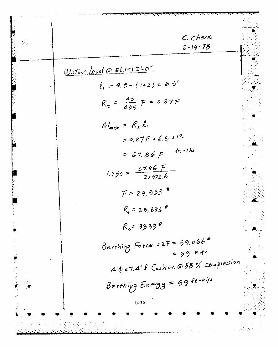
C. cen
F o87F
F x
i&t 11Li
7 z ft.X6~ x2
ID V\ cL ~ w
kS
2IrZ.
D-2930
v~

5-'5 787 o
{AJiA L~~G ~.C)3OM
II~ 4,9 '(3
R 3.
Berf~l Tvce6950iwcB9F ij
6
44~ 7." 4z F ? l cl,, e o
En ero k 2F.
D-31Z.
~4 M4

V..7
7A-fT I VL
K--
8ed~~~ii-s F~c Z 4,o
Al--"N
In /
17 J5 7 9-.-- r - ..---

U~o~k~rLe vet EL,(-) Z'-C 0' ...
131) 54 'oF. -
i': ." % ".% .'. .,
4 4 .- ,C, ... .'
or "3 .., 4 5 c o----
.- 2 -, -7 - -S.ii~~ii
3 e .0 EX tOh> i
Llmo D-33
::.S7Z.f
............:,
• ...: = e .7 "F"
---o - .
.-..-..
.. -. . -

:' C. C__ er4t i'".; "
,,. b'd(U t~ Levd L C)'.'"-. . -
= ."
:- IXA, ,1,= R1 J,&-c-
-- 76
F-. ~~~~ ~ 0 --7.7 7 F 1¢ Z.
.Rb:L 4. ,3.-.-
0--7~ 7F x- 11, x I
Bed,5 = 106. 26 2
' . .x - 2. &
;:.- = 14,g5Z 2 2-"
12 [ b " 4 , -3 " -3 AL" " "
P beyfkh,no ForVce -ZF 3- 7,7Z 0
4'4> 7. 41. u s i lo o 4 6 Co-..,F,,ess (o r
• - ~D-34 ". ,
a. --V -1 *. . - ..C.
D. 5 Pile Lateral Bearing Caipacitv in Sand
The lateral bearing capacity of the 12"1 0 nominal wooden
pile is evaluated in this section. The results will provide *
information on the fender pile penetration requirements.
7--
D-..3 5
........................
.- Z ** :
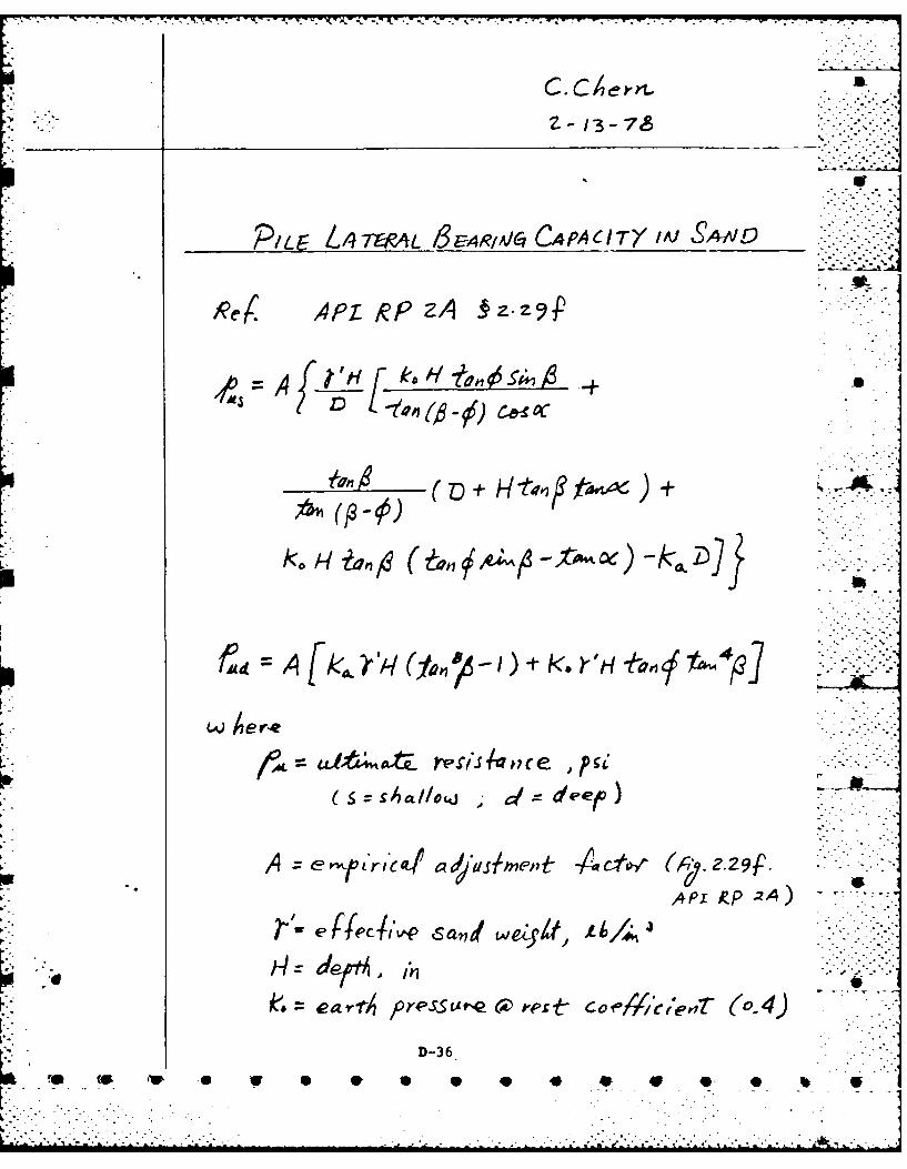
PILE 4ThPA~L /3EARI~jo C.4pACITXMJ &AAID
Re APT-pz RP -z-
4 A fLH[
A J~L k,'s1nc +, -ha44"
* H~de~o~,deep
ks. c ar Pp~sute 6D ,'es coe#enrA (o.4)
D-36

-~~ ~ ~~ ~~ -7 73rrr .- J W * .. ~ 2j
L? le
.4On
A F L
17 -. .- - .
9~3 21 tbl# .7 -
4 441~I 6z. 0 i9qz

C. C#4ern.
-~1 -7.
f ~ ~ ~ ~ V.q . x0
12 x -
,.9z 2 (/4-Hx A.921x0.3/S
o.4(0.712 o,(a9&7-o. 1)
'1f~.0376 H7~ 4 4 /
+ 0. Z35H -52j7
0 0 313A/iH1CZ96 6H t 4o9 941
D-38
S.F
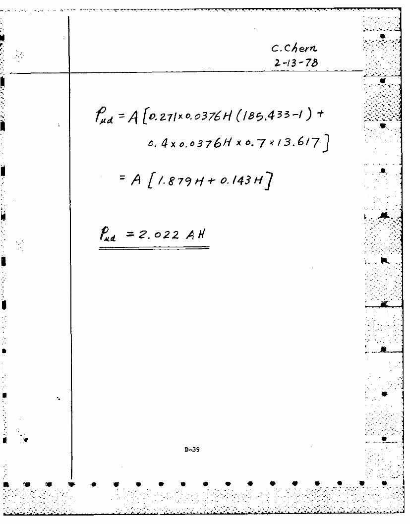
C C erf.
2.-13-7b~
Z.~ 7n10.0 oA 7,h ~33 -t
04x 0,0376H x 0.7- 1~ 3.6/73
-/1~ [&79/yHt--./143 H~]
PA 2.o22.A22
D,3
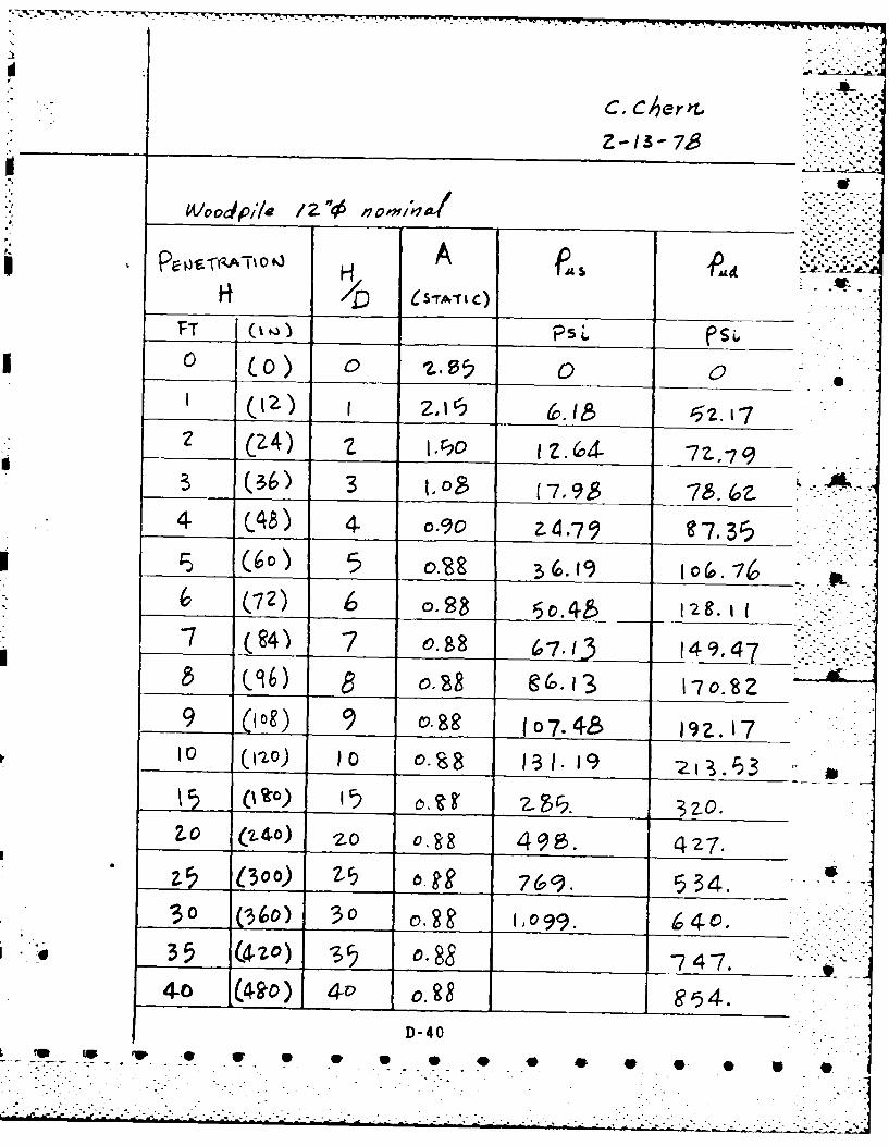
WVoodSpile 1Z2t-10
H A - -i"- n
• -
"_ _ _ __r_,_"s--A -- C)
FT__ ___ _ PsL __ __ __ _
0 00
__ _ (_6) 3 2(795-8.&4 _/8 4. ,"9 4.7" 7-3
-7 o.4 78 6-7-1 149,47& (96) 98 @(D.-'3 17.0.8 2
9 1o) 09 (74 19 Z. 17S (110) 10 0.s8 131. 19 Z "53
jj (.Co) 2. 32-0.ZO (Z4) Z 0r R 498. 427.
Z5j 000) __-_ 6. g 534.V3 (360) 30 , (7.9. 74.
35 (4,2o) S5 o.88 -_., _ 747 ,. .-
4-0 (4-90) 40 0.9_ __ .__ _7o.8_
D-409. r~ w * u * ) g * o 7. 1 . 7 '-_
• " .]-" .

C, CherrL
_FT____ LbS KiPS P
0 .4 r550.Z
____3,079 3,o79
/ t~.-6, 4-0 4-14
I~a 46 8, 46g 9i.-
11,
r. 0
6* Z64- .-.-
D. 6 Pile Driving Resistance in Sand hDriving resistance of the 12" 0 nominal fender pile isn
assumed to be the sum of the pile skin friction and the end
-point bearing capacities.
The results are used to estimate the pile driver (hammer)
requirements.
It
D-42
it 0 40 , 4

C. Cen.-14- 75 _
PILE D~iulJ/N Es Is TAA C-E /Ai 5 4l+&
4PI kipf'ZA 9g2.Zg
W here
A~=St-de sur-Acea-e. ip;e-f-
=unit e'-d beav4;,o, Cifaci-tj
7ross end a-rea-~ of ;I/eI
sand
LJ e -e c copffcer of4rde.'Ifrs'0. 74>y drAiei 0/'/e
330 A~5011Wq oil woode'i
D-43

C. cAern-&-
do 4 vC/eanH Sand.
I ~e UnL-t W Afkt rofIr-cod
A pi'/e pn? cc
(o. r2 x~ 4 0 2 600*
- . - '..-- . -44 .
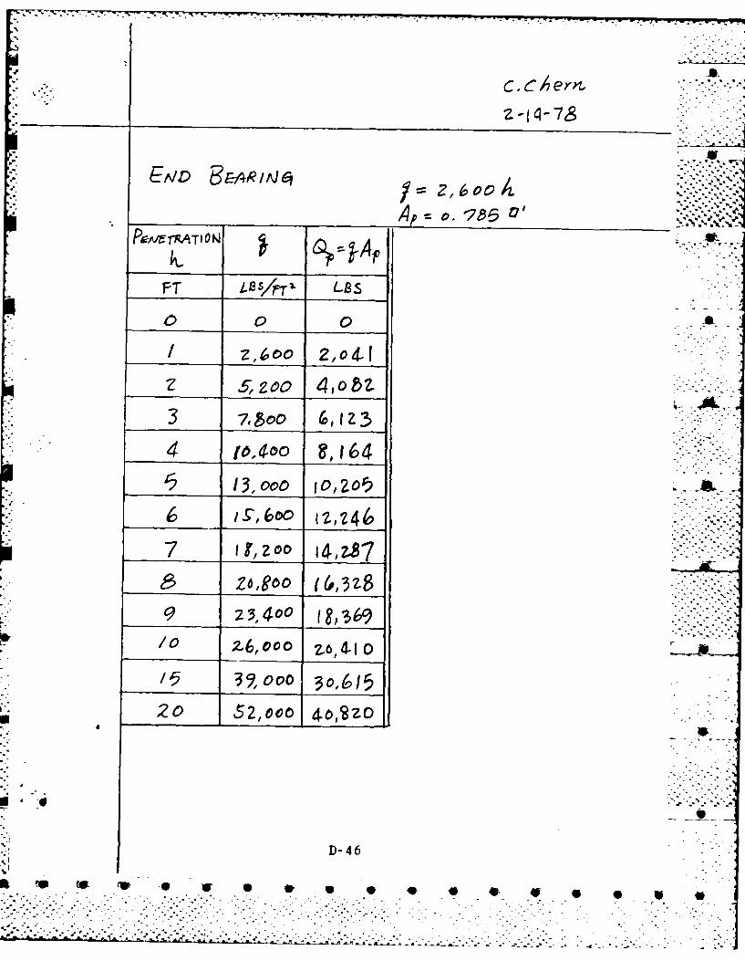
'7t
__ __ __Ap 17
FT OFTr. B
Z £zoo 4,o&2.
3 -/,boo ,IZ3
4 I1,04,0 ,i6r2 13,000 ol zor)
7, lzoo 14, 87
Z6,960 &
'9 273,400 (,b/0 ~ ~ 14 16oo 1to
"5 32,000 o(J
20 52,oco 4op2zo
D-46
0 40 4 I e,1.a ,
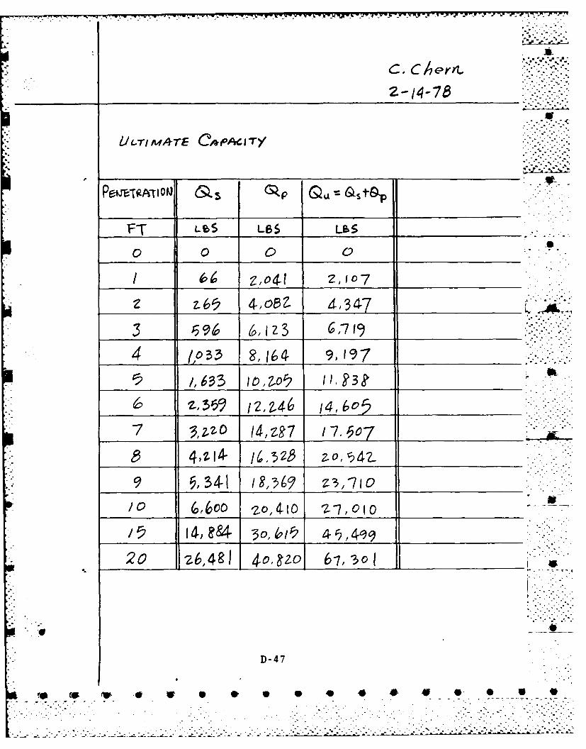
-. i,,.';.. -'- -,,3 .
.. ~C, Ch er."-.,"
________ 2-14-78
lU -r1 4'rE ,/#OACITY:
PqTF.T 10 (L S LBS &-S _________
/ _____ z~o4-l2,107_ _ _ _ _ _ _
4 ,3 14 91197 _ _ _ _ _ _
3,?- 1Z,41 __ __ __7
442.14- 1632 0, 5__ ____-
,34-1 18,69 z_" _/°,71
c,400 s.o10 'Z-7, 010
20 26,481 409ZO 6-7, 30.
D-47
, , . L.. '-.
-. ..- J..-o ~. ,.0 .o,.... .. - , _____o__ .... . ..____

. .<.> - '- .-
• 4 '. •• o. .
D.7 Berthna~ Velocity Limitation
The berthing velocity perpendicular to the pier is limited
by the berthing energy and transferred force computed previously
in the Appendix D.4. An additional constraint of the pier loading "!.. -
frame strength is then imposed at the upper limit of the berthing
velocity.
The berthing velocity is evaluated for various sizes of
tankers. The tonnage described in this section refers to the
actual tonnage of the tanker at the time of berthing operation.
- -.. -
D-48
, .. 4- 4* " ."
5 "- . ' "-'

C. CA~eryn- *~*
1* Z-j1 78
(Refs.IT 1,2,6,/i)o
W JAere -f- W4#1I
assumied 6o;1 o/ a~
= -CatL44 i~vovJje &t 0 ,~e k;)
4~~,-/Ae /0k
E,~l. 4 uJ(r E e hiv -- , 4 A -k+
D-49
lv~~~ (P 0v *4P * * * *
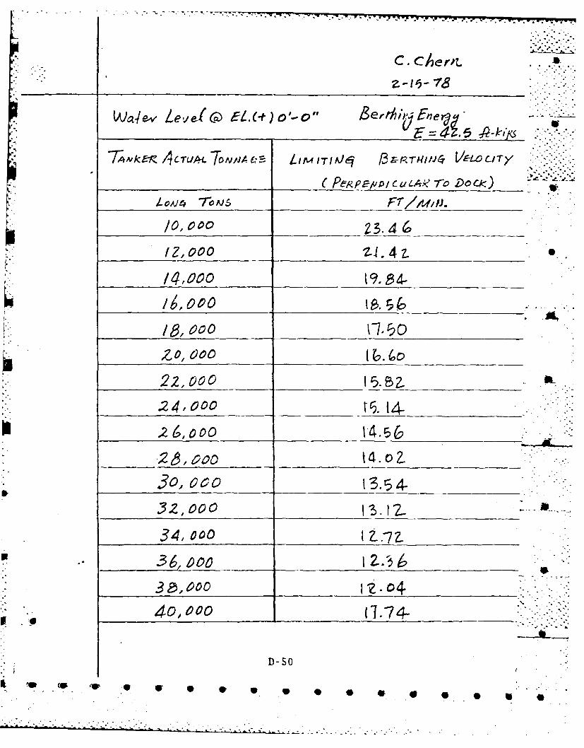
C.C~rt
7?4ANker 4ICTUALT1ONIA C LIM IT/IA)q /3-rr-Tq'in0 VELOCI/TY
/O~,coo ______Z3. 4
/0f,000 21.4 1
.24,000 _ _t9. 14-
/b, 00c0 C7.50__
652,000 B7,Z
24,900 1z4-
43o,,aoe;o t 3-574-
40140 1 .' 4-
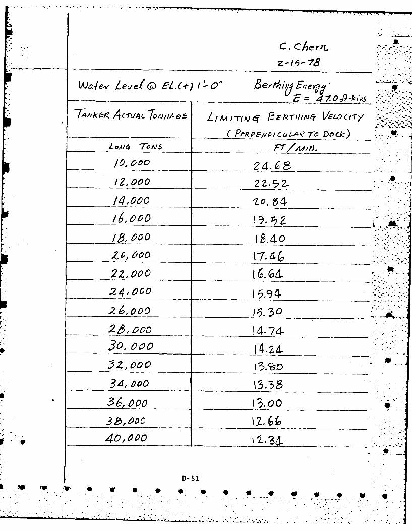
C. cerit.
C- pL,~e1A*'e-ro D 6csK)lt
/0, 000__
/,000 2Z b 4
__ _00_ __ _ (10 4-
2Z0, 000 1-7.4622,000 ______6d..24k 000 ~4:
K 6,000co
2 ,ao 14-74-
.34,000 _ _ _ _ _ _ _ _ _ _ _
36., ovo 13.00
40,002.3I
D-51.re Col.* * * * 9
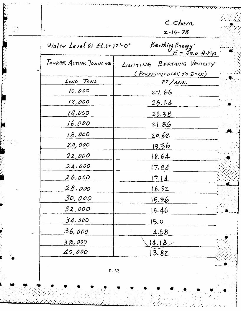
c Aerl.,
______1 -I-78
Wa~eI Leve-( c4 t5L(+) a'-o' ,ers~ Finey-v
(PeR P -rvo cuL 4,4kro D oc)
/0, 0O2-77. 66,
/Z, 000 Z1.
L9,000 f________86 ____
/lb, 000 zzZO,_6000_ _ _ _ _ _ _ _ _ _ _ _
22, 000 ~-
K:'24, 000 1784-
26000
34,00 __ _ _ __ _ _ __ _ _
w .. 36, 1-47 58
'40,000 3a
D-52
'e r~ w -e * , , *40*

t I
_______ Z -l' 78
7T,4kvE-r, /I TLjtl A d LIAAITIAe6y 13 - RTfI CY r- eC T y
(PERP ED r u.A*? -6 DO~k CJOA)4 7rOAIS
/,000 __ __2.1
/6,000 L 64D
Zo, 60007
22,000 __ _9.9(0__ __ _
.24,000 1___ _ __ __ 74_ __ _
26,o00 19.0o
___ _2_ __e__ 1734.
34, 000 1.4* 36000o - 4i)
30,400 14.88
D-S3
's ~ ~ ~ ~ f re 4b*~ ****

_____ __ ~I'~-78
b Y~(Aaj e.v Le~,c vL(- 5-o 0er thfhDFn e~.q .-
_____ _____ ___3 7= 3 0 -A-ktqS
/~' ~ - - __ _ _- -Z/. 90 _ _
0~ 600 __ __ __ __ __ __ _
.. 24OCO ___1447
.246 00 14.14,__ _ __ _ __ _ __ _
- ~ - 34 00 -.
34,00 00 I.
3__ __ ,000 _ __ 11Z4
40,0000 10.94.
D- 54
,. C ~ * U S 9 . . 9 9. 5
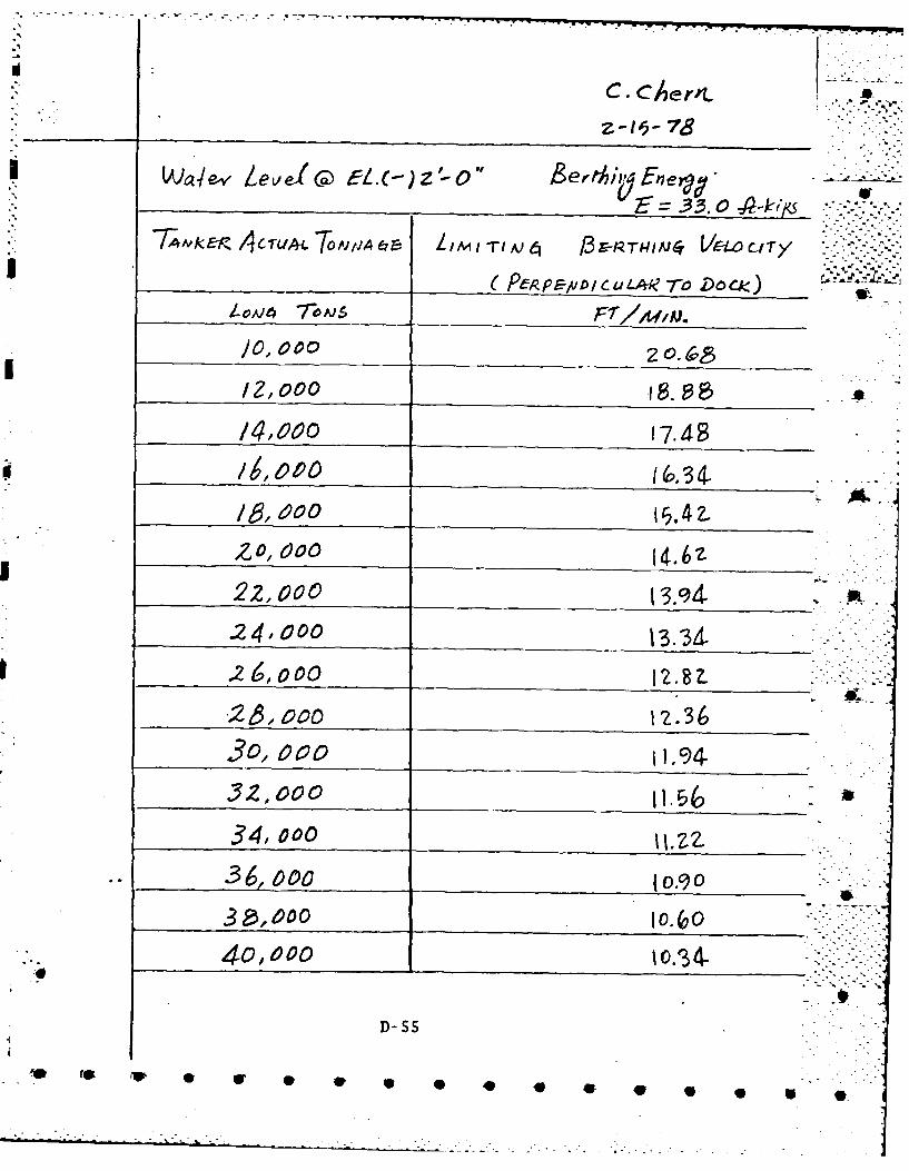
_____z z- 78
/0-3 0000
/Z.,000 1 E
1g, 00 1.4o20, 000I.~
22,000
.24k 000134
.26,ooo z.2~~ 0z 1.36
361000 0__ _ _ _ __ _ _ _ _ _
4 ,000 _ _ _ _ _ _ _ _ _ _ _ _
D- SS
*1w
V. f* ~ * 4 * * * * * S
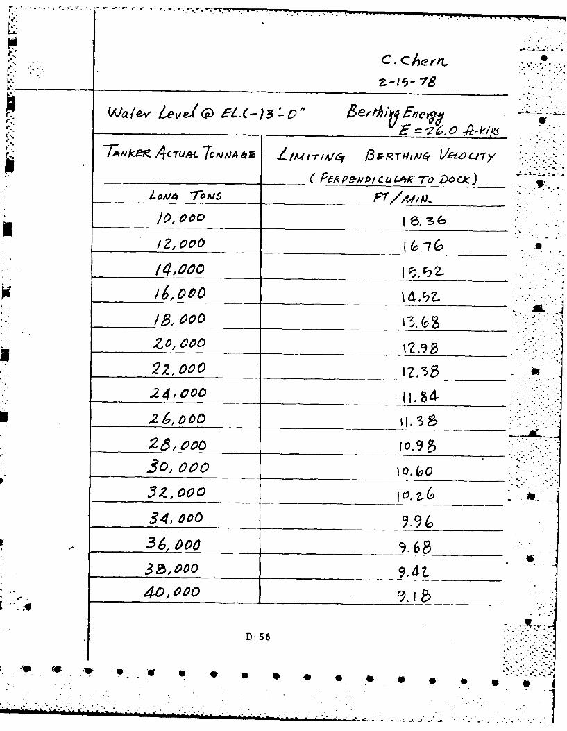
-r WC, " -Hrmjc-o cl
/0,1000__ _ _ _ S 3
/2,1000 1 2-S
/4 0 0 0 _ _ _ __ _ _ _ _ _ _
/6, 000
22,000R.24,000
-26,000og3o
~ 000 10.9
.32 ,000 _ _ _ _ _ _ _ _ _ _ _ _
34,00 9.9(036, ooo 96
3~,0009.4t.40, 000__ _ _ _ _ _ _ _ _ _ _
D- 56
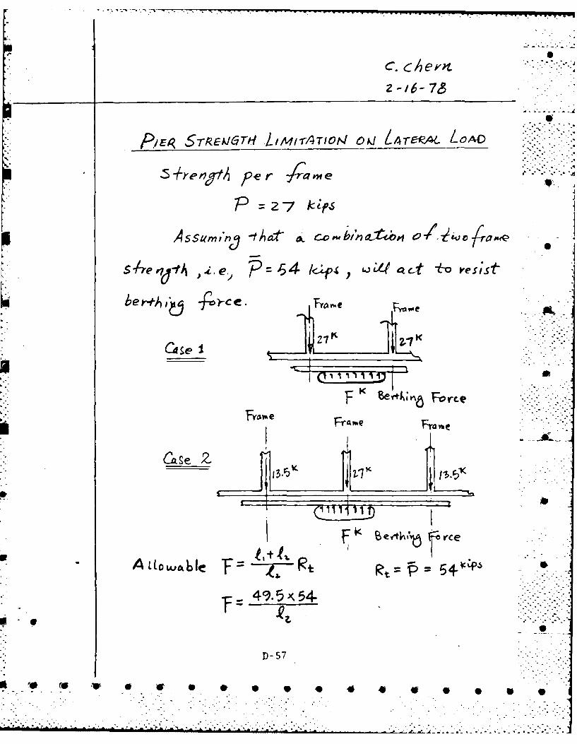
C. c ev' ' -z-16- 7&
rEP, 5TREX177GTH L1M1-rATOtr4 OJ ITA_ Lo .OAD
5-he n9 t per fI me
P =2 7 ktps
-tt° at co v o + j .4"
4e e . 4 -.p j ct-orss
t,,& ..k .-
D- 5 7 2'-4 .. . --
K Ft~ Fo rce
TheFramwe Fnv
Case Z
Fk eft"6~ rce
D- 57
-v * I 0 . 4.

-. 4.4
- F W W . - -- ".'- "Z -"-
a
_ _ _Z--16-78
/ e" Q , d. >el.0 )3 -O .. . .-
~~ .
4-4
44< 6 9. ,8 k1'
8ert/,;~ E, = 9 l-
a
U0 s0
D-58
-- '. . _ ._ . ,- ." . . .- 9 554

D.8 Loading Dolphin Dimensions
Overall dimensions of the friction resistance type dolphins
are evaluated herein. The parameters used in the calculations
are:
* T-5 tanker at 40,000 DWT
a Tanker approaching velocity perpendicular to the dolphin@ 24 ft/min.
* Dolphin will have
88 sheet piles type S32 (MP 102)
Diameter 351-011.
Height 90'-0" with 40'-0" penetration in sand
Rockfil @ 150 #/cu.ft (air weight) above mud-line
Sand @ 120 #/cu.ft (air weight)
* Hung Fender System
The results of the evaluation are: A
* Factor of safety against sliding - 5.0
* Factor of safety against overturning 2.6
D- 59
- f& t..L. -A.• p

C CerrL
3-14-7,6
7 g P/ er T- cass
Alt, Thqy7aeepeoe 7 ,Dnnqpi (L.7~ r 40,c'c
10 6
KI rAded.At 9/U.T.) = I,3 3
* ee V4vFAC D~M4~
c% /, AceXo6 ' 01 3kw (0.4/~X3.
Zx 32. Z
144c W2
0 0 (P 4F 4w 9

See MJVC ViM25
SECT;ON(W)ILLED CELLULAR PIER
f 4sAeetp jho e/e1o a4~2
d-=Fd/ E__ cri
Li~~ AererCj -
D-61
'S~~ (P 4W 0 S AW ' .
,, .Y'..... ...-.
SECT;ON .. .... '- .

- -- - S '. ~ '-,-----rr-em-
Ass dt P11 / t z 15i do(,ohh Pt (,ad wi
88dol dAeep/e AX4 At 3 A4'OL
*i-It o o - 4o~~i-4)4oxlL-4
p.~0 1 :X40; 76 00, #40264j .

cC6~errL
3 -1
CVQ-C
M LW. EtL. Ci)o0-o"
$D-6
41 )8O' 0 W

C.CAertL
3-15-78
~ Ad~n Jiyee ld,-n. e, Aqha .
44ro 4bd
Fivrm A PL PPIA ~2-2 7C(/{)
Se(A'c2i-p ovelqbuvyide4 lea v
X74 7/ x/~
-,742 Z#,/S0.FP
D- 64
'~~~~~ 4PU V~ 'U*0**** .*.

7,oa2A IAY~on 4. *eJIS#'aJce aotyoinst s//4t
~44
3,244 5.0
4-6
c Lev'Sn;l mo en 6 4,, 5 a-- * * ~ ..
~~~~~~~~~~4 9 10. i ~ ~ - - -
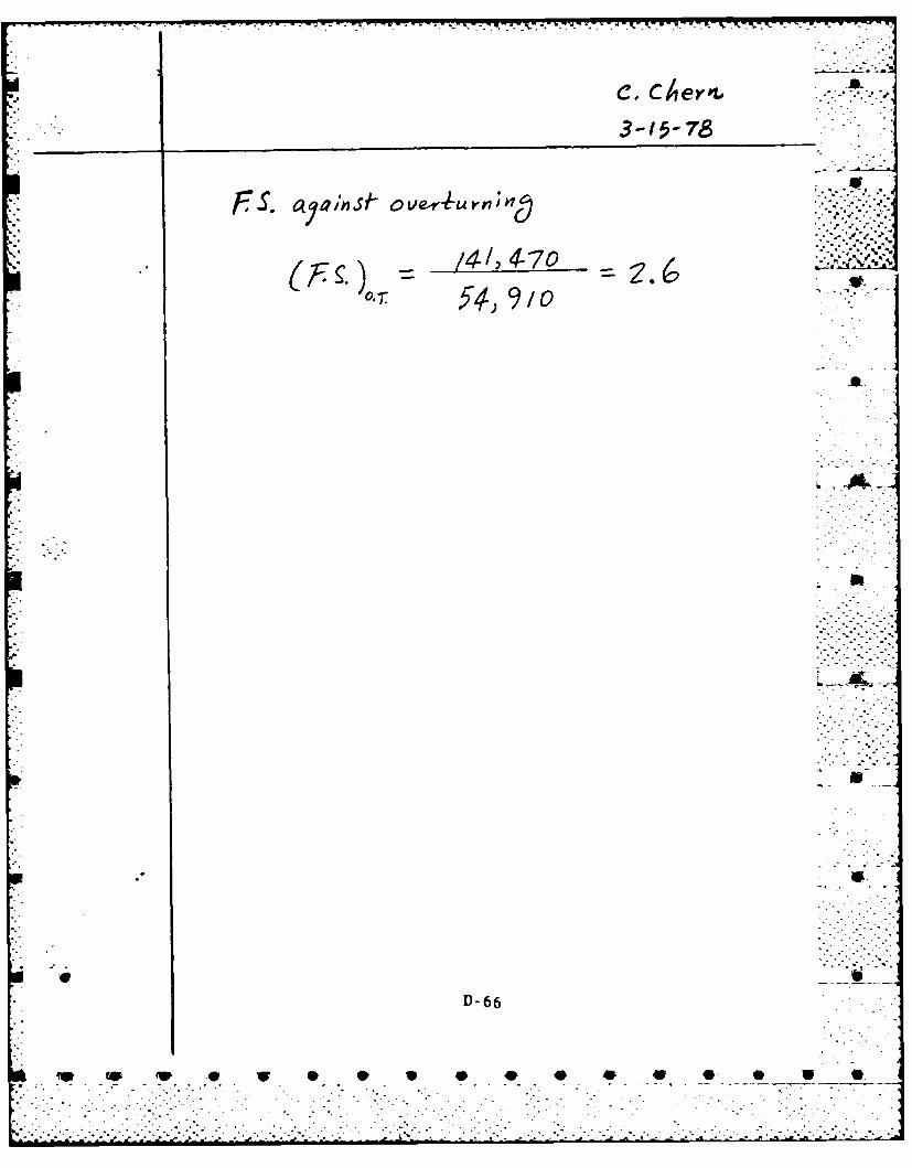
FPS. ovOnf ~Letun;na
14-* 4-, 0
3,4)910Af I
D-66
W~~~ 0 U 0*** 0 V

p I;,.
*'~1p.-.,
- LA
I,
(I K
L
&