Embed Size (px)
Citation preview

AYC-B7661 MIFARE Full-Finger Capacitive Biometric Reader/Controller Installation Manual

Copyright © 2014 by Rosslare. All rights reserved. This manual and the information contained herein are proprietary to ROSSLARE ENTERPRISES LIMITED and/or its related companies and/or subsidiaries’ (hereafter: "ROSSLARE"). Only ROSSLARE and its customers have the right to use the information.
No part of this manual may be re-produced or transmitted in any form or by any means, electronic or mechanical, for any purpose, without the express written permission of ROSSLARE.
ROSSLARE owns patents and patent applications, trademarks, copyrights, or other intellectual property rights covering the subject matter in this manual.
TEXTS, IMAGES, AND ILLUSTRATIONS INCLUDING THEIR ARRANGEMENT IN THIS DOCUMENT ARE SUBJECT TO THE PROTECTION OF COPYRIGHT LAWS AND OTHER LEGAL RIGHTS WORLDWIDE. THEIR USE, REPRODUCTION, AND TRANSMITTAL TO THIRD PARTIES WITHOUT EXPRESS WRITTEN PERMISSION MAY RESULT IN LEGAL PROCEEDINGS.
The furnishing of this manual to any party does not give that party or any third party any license to these patents, trademarks, copyrights or other intellectual property rights, except as expressly provided in any written agreement of ROSSLARE.
ROSSLARE reserves the right to revise and change this document at any time, without being obliged to announce such revisions or changes beforehand or after the fact.

Table of Contents
AYC-B7661 Installation Manual iii
Table of Contents
1. Introduction ................................................................ 8 1.1 Reader Features ...................................................................... 8 1.2 Controller Features .................................................................. 9 2. Technical Specifications ............................................ 10 3. Installation ................................................................ 12 3.1 Mounting Instructions ........................................................... 12 3.2 Wiring Instructions ................................................................ 14 3.2.1 Wiring the Unit as a Reader .......................................................... 14 3.2.2 Wiring the Unit as a Controller ..................................................... 15 4. Reader/Controller Configuration .............................. 19 4.1 Configuring the Unit ............................................................. 19 4.2 Configuration Procedure ....................................................... 19 5. Fingerprint Enrollment ............................................. 21 5.1 Enrollment in 1:N Mode ........................................................ 21 5.2 Enrollment in 1:1 Mode ......................................................... 23 5.3 Adding ID from a Card (Reader 1:N Mode) ............................. 25 6. Modes of Operation .................................................. 26 6.1 Boot Mode ........................................................................... 26 6.2 Configuration Mode .............................................................. 26 6.3 Standby Mode ...................................................................... 26 6.4 Read Mode ........................................................................... 27 6.4.1 Valid Card or Fingerprint Read ...................................................... 27 6.4.2 Invalid Card or Fingerprint Read.................................................... 28 6.5 Lockout Mode ...................................................................... 29

Table of Contents
iv AYC-B7661 Installation Manual
6.6 Factory Defaults .................................................................... 29 A. User Spreadsheet ...................................................... 30 B. Limited Warranty ...................................................... 32

List of Figures
AYC-B7661 Installation Manual v
List of Figures
Figure 1: AYC-B7661 – Mounting Orientations ............................................... 12 Figure 2: AYC-B7661 – Removing the Top Cover ............................................ 13 Figure 3: Wiring Layout for Reader Configuration ........................................... 14 Figure 4: Controller Wiring – Using a Dual-Relay Secure Application
Appurtenance .................................................................................. 17 Figure 5: Controller Wiring – Using the Internal Power .................................... 18 Figure 6: Controller Wiring – Using the External Power ................................... 18

List of Tables
vi AYC-B7661 Installation Manual
List of Tables
Table 1: Wiring the Reader to the Controller ................................................... 15 Table 2: Wiring the Unit as a Controller........................................................... 16

Notice and Disclaimer
AYC-B7661 Installation Manual vii
Notice and Disclaimer
This manual’s sole purpose is to assist installers and/or users in the safe and efficient installation and usage of the system and/or product described herein.
BEFORE ATTEMPTING TO INSTALL AND/OR USE THE SYSTEM, THE INSTALLER AND THE
USER MUST READ THIS MANUAL AND BECOME FAMILIAR WITH ALL SAFETY
REQUIREMENTS AND OPERATING PROCEDURES.
The system must not be used for purposes other than those for which it was designed.
The use of the software associated with the system and/or product, if applicable, is subject to the terms of the license provided as part of the purchase documents.
ROSSLARE exclusive warranty and liability is limited to the warranty and liability statement provided in an appendix at the end of this document.
This manual describes the maximum configuration of the system with the maximum number of functions, including future options. Therefore, not all functions described in this manual may be available in the specific system and/or product configuration you purchased.
Incorrect operation or installation, or failure of the user to effectively maintain the system, relieves the manufacturer (and seller) from all or any responsibility for consequent noncompliance, damage, or injury.
The text, images and graphics contained in the manual are for the purpose of illustration and reference only.
All data contained herein is subject to change without prior notice.
In no event shall manufacturer be liable for any special, direct, indirect, incidental, consequential, exemplary or punitive damages (including, without limitation, any and all damages from business interruption, loss of profits or revenue, cost of capital or loss of use of any property or capital or injury).
All graphics in this manual are for reference only, some deviation between the image(s) and the actual product may occur.
All wiring diagrams are intended for reference only, the photograph or graphic of the PCB(s) are intended for clearer illustration and understanding of the product and may differ from the actual PCB(s).

Introduction
8 AYC-B7661 Installation Manual
1. Introduction Rosslare’s AYC-B7661 MIFARE® Smart Card Fingerprint Capacitive Reader/Controller is a biometric fingerprint reader that is used with access control systems.
The AYC-B7661 reader uses a full-finger capacitive type biometric sensor to verify between fingerprint data and a biometric template stored in the unit (1:1 and 1:N modes). It accepts up to 107 users.
When used as a reader, the AYC-B7661 unit is compatible with most access controllers. These include the following Rosslare units: AC-015, AC-115, AC-020, AC-215, AC-225, AC-425, AC-525, and ExpansE™.
1.1 Reader Features
When using the AYC-B7661as a reader, it has the following features:
MIFARE card reading followed by fingerprint (in 1:1 mode)
Rosslare's algorithm for ID code derived from the fingerprint template (in 1:N mode)
Supports a back tamper sensor and a tamper output signal
Supports a Lockout feature for increased security
Compatible with MIFARE (ISO 14443A) 1K and 4K cards
Programmable data transmission formats
Programmable LED control and buzzer control inputs
Configuration cards created using Rosslare’s CP-R26 desktop fingerprint reader and card programmer
No PC is required for fingerprint enrollment. The unit uses cards to configure fingerprint templates.

Introduction
AYC-B7661 Installation Manual 9
1.2 Controller Features
If you connect the unit to a Rosslare PS-x25 secured power supply, it automatically functions as a controller.
When using the AYC-B7661as a controller, it includes the following features:
MIFARE card reading followed by fingerprint reading (in 1:1 mode)
Rosslare's algorithm for ID code derived from the fingerprint template (in 1:N mode)
The tamper output signal triggers the siren
Request to exit (REX) signal comes from the PS-x25 secured power supply
Pressing the REX unlocks the door that connects to output (PS-x25). The duration that the door is unlocked is configurable using the configuration card (1 to 99 seconds).
Bell feature is available with the PS-x25 secured power supply – Depends on the AUX input
Programmable door lock timer
Ability to enable or disable auxiliary input, output, and bell
No PC is required for fingerprint enrollment (unit uses cards to configure fingerprint templates)
REX input
Lock output
Aux input – This is the brown wire (LED control in Reader mode). The AUX input can either activate the AUX output for the time configured according to the Configuration card (1 to 99 sec) or activate the AUX output to toggle for every AUX input event. In addition, user can select the AUX input to activate the bell. The user can enable or disable all the AUX input features using the Configuration card.
Aux output – Depends on the AUX input
Technical Specifications
10 AYC-B7661 Installation Manual
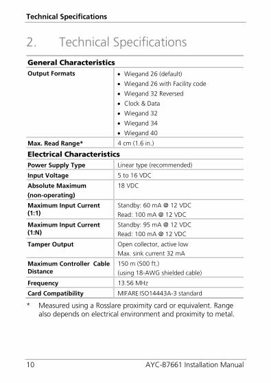
2. Technical Specifications
General Characteristics Output Formats • Wiegand 26 (default)
• Wiegand 26 with Facility code
• Wiegand 32 Reversed
• Clock & Data
• Wiegand 32
• Wiegand 34
• Wiegand 40
Max. Read Range* 4 cm (1.6 in.)
Electrical Characteristics Power Supply Type Linear type (recommended)
Input Voltage 5 to 16 VDC
Absolute Maximum
(non-operating)
18 VDC
Maximum Input Current (1:1)
Standby: 60 mA @ 12 VDC
Read: 100 mA @ 12 VDC
Maximum Input Current (1:N)
Standby: 95 mA @ 12 VDC
Read: 100 mA @ 12 VDC
Tamper Output Open collector, active low Max. sink current 32 mA
Maximum Controller Cable Distance
150 m (500 ft.) (using 18-AWG shielded cable)
Frequency 13.56 MHz
Card Compatibility MIFARE ISO14443A-3 standard
* Measured using a Rosslare proximity card or equivalent. Range also depends on electrical environment and proximity to metal.

Technical Specifications
AYC-B7661 Installation Manual 11
Environmental Characteristics Operating Temperature Range
-25°C to 60°C (-13°F to 140°F)
Operating Humidity Range 30% to 85% (non-condensing)
Physical Characteristics Dimensions (H x W x D) 100 x 54 x 42 mm (3.9 x 2.1 x 1.7 in.)
Weight 156 g (5.5 oz)

Installation
12 AYC-B7661 Installation Manual
3. Installation 3.1 Mounting Instructions
Use the supplied drilling template for finding and drilling the correct holes (Figure 1).
Figure 1: AYC-B7661 – Mounting Orientations
Be sure to protect the fingerprint sensor when the reader is mounted outside.
To mount the unit:
1. Determine an approximate surface location for the reader.
2. Peel off the back of the self-adhesive mounting label template and place it on the required mounting location.
3. Using the template as a guide, drill two holes (of the size indicated on the template) on the surface to mount the unit.
4. Insert the wall plugs into both mounting holes.
5. Drill a 10-mm (7/16”) hole for the cable. If the surface is metal, place a grommet or electrical tape around the edge of the hole.

Installation
AYC-B7661 Installation Manual 13
6. At the bottom of the unit’s case, unscrew and remove the security screw (see Figure 2), using the supplied security hex-key screwdriver.
Figure 2: AYC-B7661 – Removing the Top Cover
7. Carefully remove the snap-off front cover of the unit to reveal
two screw holes. 8. Insert the unit’s cable wire into the cable hole and move the unit
flush with the wall.
9. Using the two mounting screws, screw the unit to the wall through the two wall plugs.
10. Route the cable from the unit to the:
Controller – when configuring as a reader (Section 3.2.1)
PS-x25 power supply – when configuring as a controller (Section 3.2.2)

Installation
14 AYC-B7661 Installation Manual
The unit can also be mounted using strong epoxy glue. After application, firmly hold the unit in place until the glue dries.
11. Carefully re-attach the snap-off front cover of the unit and secure the case security screw at the bottom using the security hex key.
3.2 Wiring Instructions
3.2.1 Wiring the Unit as a Reader If you connect the unit to a standard access control unit, it automatically functions as a reader.
Figure 3: Wiring Layout for Reader Configuration
The AYC-B7661unit is connected with an 8-wire, 46-cm (18”) cable.
To connect the unit as a reader (to a controller):
1. Prepare the unit's cable by cutting the cable jacket back 3.2 cm (1¼”) and strip the wire 1.3 cm (½”).
2. Prepare the controller cable by cutting the cable jacket back 3.2 cm (1¼”) and strip the wire 1.3 cm (½”).
3. Splice the unit’s pigtail wires to the corresponding controller wires (Table 1) and cover each connection.

Installation
AYC-B7661 Installation Manual 15
Table 1: Wiring the Reader to the Controller
Color Wiring Black/Shield Ground
Red Vin
Green Data 0
White Data 1
Brown LED control
Purple Tamper
4. If the tamper output is being utilized, connect the purple wire to the correct input on the controller.
5. Trim and cover all conductors that are not used.
• The individual wires extending from the reader are color-coded according to the required Wiegand standard.
• When using a separate power supply for the reader, this supply and the controller’s power supply must have a common ground. A linear power supply is recommended.
• Attach the cable shield wire on the reader to an earth ground (best), or to a signal ground connection at the panel or power supply end of the cable. This configuration is best for shielding the reader cable from external interference.
3.2.2 Wiring the Unit as a Controller If you connect the unit to a Rosslare PS-x25 secured power supply, it automatically functions as a controller.
The AYC-B7661unit is connected with an 8-wire, 46-cm (18”) cable.
To connect the unit as a controller:
1. Prepare the unit's cable by cutting the cable jacket back 3.2 cm (1¼”) and strip the wire 1.3 cm (½”).
2. Prepare the PS-x25 secured power supply’s cable by cutting the cable jacket back 3.2 cm (1¼”) and strip the wire 1.3 cm (½”).

Installation
16 AYC-B7661 Installation Manual
3. Splice the controller pigtail wires to the corresponding PS-x25 secured power supply’s wires (see Table 2) and cover each connection.
Table 2: Wiring the Unit as a Controller
Controller Color Functionality Note
5~16 VDC Red +DC Input Wired to the PS-x25
Shield/ Ground Black Ground Wired to the PS-x25
C 1 White Communication Wired to the PS-x25
C 2 Green Communication Wired to the PS-x25
AUX. IN Brown Auxiliary Input Wired to input
Attach the cable shield wire on the unit to an earth ground (best). You can also attach it to a signal ground connection at the panel or power supply end of the cable. This configuration is best for shielding the controller cable from external interference.
4. Trim and cover all conductors not used.
5. To connect the unit to the desired power supply option, refer to the relevant wiring diagrams that follow.

Installation
AYC-B7661 Installation Manual 17
Figure 4 shows the wiring for the controller application using a dual-relay secure application appurtenance.
Figure 4: Controller Wiring – Using a Dual-Relay Secure Application Appurtenance

Installation
18 AYC-B7661 Installation Manual
Figure 5 shows the auxiliary output connection using the internal power.
Figure 5: Controller Wiring – Using the Internal Power
Figure 6 shows the auxiliary output connection using the external power.
Figure 6: Controller Wiring – Using the External Power

Reader/Controller Configuration
AYC-B7661 Installation Manual 19
4. Reader/Controller Configuration 4.1 Configuring the Unit
To provide the highest level of security, the reader is programmed to validate only MIFARE cards whose settings correspond to the Master card that is used to bring the reader into Configuration mode, where the following settings can be configured:
Card transfer format
MIFARE card Key A value
LED and buzzer control enable
Lock-out settings
Transmission of Card Serial Number (CSN) or card ID from dedicated sector
In addition, it is possible to browse between 1:1 and 1:N modes.
The Master and Configuration cards are configured using the Desktop Programmer (CP-R26). Refer to the CP-R26 Hardware and AS-B01 Software Manual for more details.
4.2 Configuration Procedure
The reader does not work until it is configured upon initial use. It is recommended to configure the reader one time only, following installation and its initial use. However, if needed, configuring the reader can be done anytime using the same procedure described below.
To configure the unit:
1. Present the Master card.
A short beep is generated and the two LEDs begin to blink in orange, as the reader goes into Configuration mode.
2. Within 30 seconds (while the reader is still in Configuration mode), present a valid Configuration card to the reader.

Reader/Controller Configuration
20 AYC-B7661 Installation Manual
If the configuration is valid, 3 short beeps are emitted, and both LEDs flash in green 3 times quickly together.
If the configuration is not valid, an error beep is generated. If the reader is being configured for the first time, the reader will not work until a successful configuration is performed.
If the reader is already in use, then following a failed configuration, the reader returns to Standby mode and continues to work with its previous configuration settings.

Fingerprint Enrollment
AYC-B7661 Installation Manual 21
5. Fingerprint Enrollment After configuring the unit, either as a reader or as a controller, you need to enroll fingerprints (1:N) or fingerprints and cards (1:1) into the unit.
For configuration and fingerprint enrollment, you need to use the following pre-configured cards:
Enroll
Add card
Delete
+1
+10
You need Rosslare's CP-R26 unit to generate these cards.
5.1 Enrollment in 1:N Mode
In 1:N mode, the unit identifies users according to their fingerprints only.
Before enrolling users, it is recommended to create a list of all users and their record number (see Appendix A). The unit accepts up to 107 users.
To enroll fingerprints:
1. For first time use, configure the reader as explained in Chapter 4.
2. When the reader is in Standby mode, present the Enroll card to the reader. Both LEDs flash orange.
The 'enroll', '+1','+10', 'add card', and 'delete' are the same for both the 1:1 and 1:N modes.

Fingerprint Enrollment
22 AYC-B7661 Installation Manual
3. Present the record number (+10 and +1) cards the number of times required to reach the desired record number, each time a card is presented the reader emits 1 beep.
For example, to enroll a fingerprint to record number 32, present the +10 card three times followed by the +1 card twice.
4. Present the Enroll card. The right LED flashes green and the left LED is off.
5. Ask users to place their finger on the capacitive sensor.
When it successfully identifies the fingerprint, the unit emits one short beep.
6. Ask users to place their finger on the unit’s sensor once more.
If valid, the unit emits three short beeps and the LEDs blink green. The user’s fingerprint template is then stored in the defined record within the unit.
If an enrollment error occurs, the unit emits an error tone and the LEDs turn red for about one second.
For people who cannot enroll their finger:
• In Reader mode, there is an option to use the reader with card only CSN or sector.
• In Controller mode, you can enroll a user card with the Add Card process (Section 5.3).
To delete enrolled fingerprints in 1:N mode:
1. When the reader is in Standby mode, present the Delete card to the reader.
Both LEDs flash orange.
2. Present the record number (+10 and +1) cards the number of times required to reach the desired record number.
Each time a card is presented the reader emits one beep.
For example, to enroll a fingerprint to record number 32 present the +10 card three times followed by the +1 card twice.

Fingerprint Enrollment
AYC-B7661 Installation Manual 23
3. Present the Delete card.
If valid, the unit emits three short beeps and the LEDs blink green. The users do not need to place their finger on the unit’s sensor.
If an error occurs, the unit emits an error tone and the LEDs turn red for about one second.
5.2 Enrollment in 1:1 Mode
In 1:1 mode, the unit identifies users according to their fingerprints and their user MIFARE smart cards.
Before enrolling users, it is recommended to create a list of all users and their record number (see Appendix A). The unit accepts up to 107 users.
To enroll cards and fingerprints:
1. For first time use, configure the reader as explained in Chapter 4.
2. When the reader is in standby mode, present the Enroll card to the unit.
Both LEDs flash orange.
3. Present the record number (+10 and +1) cards the number of times required to reach the desired record number.
Each time a card is presented the reader emits one beep.
For example, to enroll a fingerprint to record number 32 present the +10 card three times followed by the +1 card twice.
4. Present the Enroll card, and then present the user’s card.
The right LED flashes green and the left LED turns off. The unit emits a long beep.
5. Ask users to place their finger on the unit’s sensor once for first identification. When it successfully identifies the fingerprint, the unit emits one short beep.
6. Ask users to place their finger on the unit’s sensor once more.

Fingerprint Enrollment
24 AYC-B7661 Installation Manual
If valid, the unit emits three short beeps and the LEDs blink green. The user’s fingerprint template is then stored in the defined record within the unit.
If an enrollment error occurs, the unit emits an error tone and the LEDs turn red for about one second.
To delete enrolled users (fingerprint and user card) in 1:1 mode:
1. When the reader is in Standby mode, present the Delete card to the reader.
Both LEDs flash orange.
2. Present the record number (+10 and +1) cards the number of times required to reach the desired record number.
Each time a card is presented the reader emits one beep.
For example, to enroll a fingerprint to record number 32 present the +10 card three times followed by the +1 card twice.
3. Present the Delete card.
If valid, the unit emits three short beeps and the LEDs blink green. The users do not need to place their finger on the unit’s sensor.
If an error occurs, the unit emits an error tone and the LEDs turn red for about one second.
To add a user card to an ex isting fingerprint record:
1. When the reader is in Standby mode, present the Add card configuration card to the reader.
Both LEDs flash orange.
2. Present the record number (+10 and +1) cards the number of times required to reach the desired record number.
Each time a card is presented the reader emits one beep.
For example, to enroll a fingerprint to record number 32 present the +10 card three times followed by the +1 card twice.

Fingerprint Enrollment
AYC-B7661 Installation Manual 25
3. Present the Add card configuration card followed by the user’s card.
If valid, the unit emits three short beeps and the LEDs blink green. The user’s fingerprint template is then stored in the defined record within the unit.
If an enrollment error occurs, the unit emits an error tone and the LEDs turn red for about one second.
In 1:1 mode, up to two cards can be enrolled per user in each slot.
5.3 Adding ID from a Card (Reader 1:N Mode)
After normal enrollment, the ID code sent to the controller is based on the Rosslare's algorithm. However, you can link the user card's ID to the template. In this case, the user's ID is sent to the controller instead of the previous ID.
To add an ID from a user card:
1. Present the Add Card card.
Both LEDs flash orange.
2. To get to the desired record number, do one of the following:
Ask the users whose ID cards you wish to add to place the finger linked to each record number.
Present the record number (+10 and +1) cards the number of times required to reach the desired record number.
3. Present the Add card card.
4. Present the user’s card.
If valid, the unit emits three short beeps and the LEDs blink green. The user’s fingerprint template is then stored in the defined record within the unit.
If an error occurs because the ID from the user’s card already exists inside the unit's database, the unit emits an error tone and the LEDs turn red for about one second.

Modes of Operation
26 AYC-B7661 Installation Manual
6. Modes of Operation The AYC-B7661 has the following modes of operation:
Boot Mode (reset)
Configuration Mode
Standby Mode
Read Mode
Lockout Mode
Factory Defaults
6.1 Boot Mode
The reader enters Boot mode upon power up or upon restoration of power after a power failure where the loader runs separately from the main application. The Boot mode lasts for approximately three seconds, during which the red LEDs flash simultaneously.
6.2 Configuration Mode
Refer to Section 4.2 on how set the reader to Configuration mode.
The Configuration card is configured using the Desktop Reader (CP-R26) and the Card programmer and Fingerprint enrollment. Refer to the CP-R26 Hardware and AS-B01 Software Manual for more details.
6.3 Standby Mode
The reader enters Standby mode:
After the Boot (reset) and Configuration modes
After the Lockout mode period
After a successful card or fingerprint read
During Standby mode, the left red LED remains lit to indicate Standby mode and the reader is ready for normal use.

Modes of Operation
AYC-B7661 Installation Manual 27
6.4 Read Mode
Depending on the mode of operation configured, the unit behaves as follows:
1:N Mode
The unit recognizes user fingerprints enrolled in Standby mode. On a valid verification of the fingerprint template reading, it transfers the user ID to the controller.
1:1 Mode
The unit enters Read mode when users present a MIFARE card, followed by placing their finger. The card or fingerprint can have a valid or invalid value or match.
Following a validated card read, the right LED blinks green, indicating to users to place their finger on the unit’s sensor.
In either mode, for people who cannot enroll their finger, there is an option to use the reader with card only CSN or sector.
6.4.1 Valid Card or Fingerprint Read When card and/or fingerprint reads are valid, the following sequence occurs:
6.4.1.1 In 1:N Mode
1. While the unit is in Standby mode, users place their finger on the unit’s sensor.
When the unit finds a template match, it emits three short beeps and the two LEDs flash green.
2. The unit sends the data to the access controller, according to its configured transmission format.
The unit then re-enters Standby mode.
6.4.1.2 In 1:1 Mode
1. While the unit is in Standby mode, users present their MIFARE
smart card to the unit.

Modes of Operation
28 AYC-B7661 Installation Manual
2. The unit emits a short beep and the right green LED flashes. This shows that the unit is waiting a user to place a finger on the sensor.
3. The users place their finger on the fingerprint sensor. When the unit finds a match, it emits three short beeps and the two green LEDs to indicate success.
If the user does not place a finger within 10 seconds, the unit returns to Standby mode and the user must restart the identification procedure.
4. The unit sends the data to the access controller, according to its configured transmission format. The unit then re-enters Standby mode.
6.4.2 Invalid Card or Fingerprint Read An invalid card or fingerprint read can occur when:
There is an error in fingerprint presentation (for example, a user places the finger incorrectly)
There is a mismatch between the fingerprint and the template (for example, a user presents the wrong finger)
An invalid card read can occur when the card is not verified. When a card or fingerprint read is invalid, the following sequence occurs:
1. If the fingerprint is wrong or the card (in 1:1 mode) is invalid, the two LEDs turn red and the buzzer emits a long, low beep. The user can then re-attempt finger presentation.
2. Based on the Lockout mode configuration (Section 6.5), several invalid reads within 30 seconds puts the unit into Lockout mode.
If there are fewer than the preconfigured number of invalid card or fingerprint reads within 30 seconds, the unit enters Standby mode.

Modes of Operation
AYC-B7661 Installation Manual 29
In Reader mode, when using Rosslare’s controllers and AxTrax™ software, the unit sends specific messages when failures occur. The AxTrax™ software can handle the following messages:
• Fingerprint data reading from card failed
• Fingerprint reading failed
• Fingerprint capacitive sensor / card verification failed
6.5 Lockout Mode
The reader enters Lockout mode when there are a number of invalid card and/or finger reads within a 30-second period. During Lockout mode, the two LEDs flash red simultaneously for 1 minute. After 1 minute, the reader enters Standby mode.
The default number of invalid reads before the reader enters Lockout mode is 5. The number of invalid reads can be programmed to be 1-10.
The default duration of Lockout mode is 1 minute. The duration can be programmed to be 1-5 minutes.
6.6 Factory Defaults
Upon initial power up, the unit remains in Factory Default mode until valid Master and Configuration cards are presented.

Modes of Operation
30 AYC-B7661 Installation Manual
A. User Spreadsheet
User # User Name User # User Name
1. 55.
2. 56.
3. 57.
4. 58.
5. 59.
6. 60.
7. 61.
8 62.
9. 63
10. 64.
11. 65.
12. 66.
13. 67.
14. 68.
15. 69.
16. 70.
17. 71.
18. 72.
19. 73.

User Spreadsheet
AYC-B7661 Installation Manual 31
20. 74.
21. 75.
22. 76.
23. 77.
24. 78.
25. 79.
26. 80.

Limited Warranty
32 AYC-B7661 Installation Manual
B. Limited Warranty The full ROSSLARE Limited Warranty Statement is available in the Quick Links section on the ROSSLARE website at www.rosslaresecurity.com.
Rosslare considers any use of this product as agreement to the Warranty Terms even if you do not review them.

AYC-B7661
Asia Pacific, Middle East, Africa Rosslare Enterprises Ltd.
Kowloon Bay, Hong Kong
Tel: +852-2795-5630
Fax: +852-2795-1508
United States and Canada Rosslare Security Products, Inc.
Southlake, TX, USA
Toll Free: +1-866-632-1101
Local: +1-817-305-0006
Fax: +1-817-305-0069
Europe Rosslare Israel Ltd.
Rosh HaAyin, Israel
Tel: +972-3-938-6838
Fax: +972-3-938-6830
Latin America Rosslare Latin America
Buenos Aires, Argentina
Tel: +54-11-4001-3104
China Rosslare Electronics (Shenzhen) Ltd.
Shenzhen, China
Tel: +86-755-8610 6842
Fax: +86-755-8610 6101
India Rosslare Electronics India Pvt Ltd.
Tel/Fax: +91-20-40147830
Mobile: +91-9975768824
0706
-096
0394
+02


![Evs1a[Ntlu, Ayc,Myd]Rev.biblio](https://img.dokumen.tips/doc/110x75/563db93a550346aa9a9b4d42/evs1antlu-aycmydrevbiblio.jpg)