Embed Size (px)
Citation preview
SP
EC
SH
EE
T
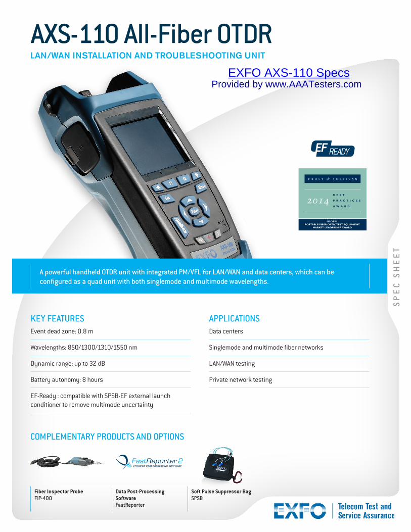
A powerful handheld OTDR unit with integrated PM/VFL for LAN/WAN and data centers, which can be configured as a quad unit with both singlemode and multimode wavelengths.
Fiber Inspector ProbeFIP-400
Data Post-Processing SoftwareFastReporter
Soft Pulse Suppressor BagSPSB
COMPLEMENTARY PRODUCTS AND OPTIONS
KEY FEATURESEvent dead zone: 0.8 m
Wavelengths: 850/1300/1310/1550 nm
Dynamic range: up to 32 dB
Battery autonomy: 8 hours
EF-Ready : compatible with SPSB-EF external launch conditioner to remove multimode uncertainty
APPLICATIONSData centers
Singlemode and multimode fiber networks
LAN/WAN testing
Private network testing
AXS-110 All-Fiber OTDRLAN/WAN INSTALLATION AND TROUBLESHOOTING UNIT
2014
GLOBALPORTABLE FIBER OPTIC TEST EQUIPMENT
MARKET LEADERSHIP AWARD
EXFO AXS-110 SpecsProvided by www.AAATesters.com

AXS-110 All-Fiber OTDR
TECHNICAL SPECIFICATIONS a
Wavelengths (nm) 850/1300/1310/1550
Dynamic range b (dB) 24/25/32/30
Pulse width (ns) Multimode: 5, 10, 30, 100, 275, 1000
Singlemode: 5, 10, 30, 100, 275, 1000, 2500, 10 000
Event dead zone c (m) 0.8
Attenuation dead zone c (m) 3.5/4.5/4/4.5
Linearity (dB/dB) ±0.03
Loss threshold (dB) 0.01
Loss resolution (dB) 0.01
Sampling resolution (m) Multimode: 0.08 to 2.5; singlemode: 0.08 to 5.0
Sampling points Up to 64 000
Distance uncertainty d (m) ±(0.75 + 0.0025 % x distance + sampling resolution)
Distance range (km) Multimode: 0.1 to 40; singlemode: 0.65 to 260
Typical real-time refresh (Hz) 4
Memory capacity 500 traces
Measurement time User-defined
Stable source output power e (dBm) Multimode: –3; singlemode: –2.5
Visual fault locator (optional)
Laser, 650 nm ± 10 nm CW typical Pout = 1.4 mW open beam
2
1
4
5
3
8 9
10
6
7
1 Infrared Printer Interface
2 OTDR Port | Multimode testing.
3 Power Meter Detector Port | Compatible with almost every connector on the market. Manually and efficiently perform power and loss testing. Accurately measure power up to 26 dBm.
4 OTDR Port | Singlemode testing.
5 VFL Port | Built-in 650 nm visual fault location on a universal 2.5 mm connector.
6 AC Adapter
7 RJ-45 | TCP/IP testing.
8 USB B | Data transfer using ActiveSync or remote control.
9 USB A | Data transfer using memory stick.
10 Fiber Inspection Probe Port
TROUBLESHOOTING OF HIGH-SPEED MULTIMODE NETWORKS WITH ENCIRCLED FLUX (PRELIMINARY)
Whether it’s for an expanding enterprise-class business or a large-volume data center, new high-speed data networks built with multimode fibers are running under tighter tolerances than ever before. In case of failure, intelligent and accurate test tools are needed to quickly find and fix the fault.
Multimode fibers are the trickiest links to test because the test results are highly dependent on each device’s output conditions. Troubleshooting with a different unit than the construction unit may mislead the technician or result in the inability to find the fault, creating longer network downtimes.
For multimode fibers, EXFO recommends using an external launch mode conditioner that is encircled flux (EF) compliant. The encircled flux standard (as recommended in TIA-568 via TIA-526-14-B and IEC 61280-4-1 Ed. 2.0) is a way of controlling the source launch conditions so that Tier-2 troubleshooting can be performed with maximum accuracy and consistency.
The use of an external EF-compliant device* such as the SPSB-EF-C30 will ensure a fast and easy way to fix faulty networks.* For more detailed information about encircled flux compliance, please read the encircled flux test solution specification sheet.
SPSB-EF-C30

EXFO is certified ISO 9001 and attests to the quality of these products. EXFO has made every effort to ensure that the information contained in this specification sheet is accurate. However, we accept no responsibility for any errors or omissions, and we reserve the right to modify design, characteristics and products at any time without obligation. Units of measurement in this document conform to SI standards and practices. In addition, all of EXFO’s manufactured products are compliant with the European Union’s WEEE directive. For more information, please visit www.EXFO.com/recycle. Contact EXFO for prices and availability or to obtain the phone number of your local EXFO distributor.
For the most recent version of this spec sheet, please go to the EXFO website at www.EXFO.com/specs.
In case of discrepancy, the Web version takes precedence over any printed literature.
EXFO Headquarters > Tel.: +1 418 683-0211 | Toll-free: +1 800 663-3936 (USA and Canada) | Fax: +1 418 683-2170 | [email protected] | www.EXFO.com
EXFO serves over 2000 customers in more than 100 countries. To find your local office contact details, please go to www.EXFO.com/contact.
AXS-110 All-Fiber OTDR
Notes
a. Refer to the example. First select the singlemode connector, and then the multimode connector or the live port connector.
b. Singlemode only.
c. Multimode only.
d. Mandatory with FP4S or FP4D.
SPAXS110.3AN © 2014 EXFO Inc. All rights reserved. 2008
Printed in Canada 14/07
ORDERING INFORMATION
ModelAXS-110-12CD = Dual-wavelength MM OTDR 850/1300 nm
(50/125 µm, 62.5/125 µm)AXS-110-12CD-23B = Four-wavelength MM/SM all-fiber OTDR 850/1300 nm
(50/125 µm, 62.5/125 µm) and 1310/1550 nm (9/125 µm)
Connector a
EA-EUI-28 = APC/DIN 47256 b
EA-EUI-89 = APC/FC, narrow key b
EA-EUI-91 = APC/SC b
EA-EUI-95 = APC/E-2000 b
EA-EUI-98 = APC/LC b
EI-EUI-28 = UPC/DIN 47256EI-EUI-76 = UPC/HMS-10/AGEI-EUI-89 = UPC/FC, narrow keyEI-EUI-90 = UPC/STEI-EUI-91 = UPC/SCEI-EUI-95 = UPC/E-2000EI-EUI-98 = UPC/LC c
Power meter00 = Without power meter PM2X = With GeX power meter
AXS-110-XX-XX-XX-XX-XX-XX-XX
Example: AXS-110-12CD-23B-EA-EUI-89-EI-EUI-95-PM2X-FOA-22-VFL-FP4S-SK1-SK2-SK3
Software summary kitSK1 = SmartKit including macrobending detection,
pass/fail and fault finderSK2 = IP testingSK3 = Fiber inspection probe software d
Probe option00 = Without probeFP4S = Inspection probe (400x) FP4D = Inspection probe (200x/400x)
VFL00 = Without visual fault locator VFL = With visual fault locator
Connector adapterFOA-12 = BiconicFOA-14 = D4, D4/PCFOA-16 = SMA/906FOA-22 = FC, FC (PC/SPC/UPC/APC), NEC-D3FOA-28 = DIN 47256 (LSA): DIN 47256 (PC/APC)FOA-32 = ST, ST (PC/SPC/UPC)FOA-54 = SC (PC/SPC/UPC/APC)FOA-78 = Radiall ECFOA-96B = E-2000/APCFOA-98 = LCFOA-99 = MU
Notes
a All specifications valid at 23 °C ± 2 °C (73.4 °F ± 3.6 °F) with an FC/PC connector, unless otherwise specified.
b. Typical dynamic range with longest pulse and three-minute averaging at SNR = 1. Multimode dynamic range is specified for 62.5 µm fiber; a 3 dB reduction is seen when testing 50 µm fiber. AXS-110-12CD-23B is 21/22/37/35. Singlemode dynamic range is unaffected by 50 µm fiber (different port).
c. Typical dead zone for multimode reflectance below –35 dB and singlemode reflectance below –45 dB, using shortest pulse.
d. Does not include uncertainty due to fiber index.
e. Typical output power is given at 1300 nm for multimode output and 1550 nm for singlemode output.
f. At 23 ºC ± 1 ºC, 1550 nm and with FC connector. With OTDR in idle mode, battery operated.
g. For ±0.05 dB, from 18 ºC to 28 ºC.
OPTIONAL POWER METER f
Calibrated wavelengths (nm)
850, 1270, 1290, 1310, 1330, 1350, 1370, 1390, 1410, 1430, 1450, 1470, 1490, 1510, 1530, 1550, 1570, 1590, 1610, 1625
Power range (dBm) 26 to –64 (GeX 2 mm)
Uncertainty ±5 % ± 0.4 nW (up to 5 dBm)
Display resolution (dB)
0.01 (–54 dBm to Pmax) 0.1 (–54 dBm to –64 dBm) 1 (–64 dBm to min)
Automatic offset nulling range g Maximum power to —38 dBm
Tone detection (Hz) 270/1000/2000
GENERAL SPECIFICATIONSSize (H x W x D) 250 mm x 125 mm x 75 mm (9 7/8 in x 4 15/16 in x 3 in)
Weight 1 kg (2.2 lb)
Temperature operating –18 °C to 50 °C (14 °F to 122 °F)
storage –40 °C to 70 °C (–40 °F to 158 °F)
Relative humidity 0 % to 95 % non-condensing
PowerLi-ion batteries; 8 hours of continuous operation as per Bellcore TR-NWT-001138
Warranty (years) 1
LASER SAFETY