Embed Size (px)
Citation preview

Revision 3 September 20, 2017
Individual chapters of the Kalsi Seals Handbook are periodically updated. To determine if a newer revision of this chapter exists, please visit www.kalsi.com/seal-handbook.htm.
NOTICE: The information in this chapter is provided under the terms and conditions of the Offer of Sale, Disclaimer, and other notices provided in the front matter of this handbook.
Document 3377 © 2014 Kalsi Engineering, Inc. All rights reserved.
Kalsi Seals Handbook
Chapter D17
Axially force balanced, laterally floating backup rings

Axially force balanced, laterally floating backup rings Chapter D17 Page 1
Contact Kalsi Engineering Search this handbook
1. Introduction
One factor that sets Kalsi Engineering apart from other seal companies is our ability to
provide detailed seal implementation advice, based on decades of mechanical design and
seal testing experience. This enables our customers to take a systems approach to design,
achieving maximum rotary seal performance.
Over the years, Kalsi Engineering has conducted research to determine the best ways
to employ Kalsi Seals in high pressure sealing applications that involve runout,
misalignment, and pressure-induced component deformation. The result has been a series
of mechanical improvements,1,2,3,4 culminating in the patented5 floating backup ring
arrangements that are described in this chapter. These backup ring arrangements are
axially force balanced, and radially pressure balanced. These features allow the smallest
practical extrusion gap to be used, while accommodating shaft runout and misalignment.
By minimizing the extrusion gap, the rotary seals can seal higher pressures for longer
periods of time.
Licensing and technical assistance
The floating backup ring arrangements are applicable to many different types of
equipment, including rotating control devices, oilfield washpipe assemblies, hydraulic
swivels, etc. Contact Kalsi Engineering to obtain technical assistance and discuss
licensing options, which can range from a per-unit royalty to incorporating the royalty into
the seal price.
2. Description of the problem
Rotary seals are sometimes used to retain high lubricant within a housing by sealing
the clearance between the housing and a bearing-guided rotatable shaft. The clearance is
often referred to as the extrusion gap. High pressure, combined with eccentric shaft motion,
is a significant challenge for any rotary seal. The seal can withstand higher pressure if the
extrusion gap clearance between the housing and the shaft is small, but the clearance must
be large enough to accommodate the full potential range of shaft misalignment, runout, and
load-related deflection. Inadequate clearance between the housing and the shaft results in
1 U.S. Patent 5,195,754, March 23, 1993, Laterally translating seal carrier for a drilling mud motor sealed
bearing assembly.
2 U.S. Patent 6,007,105, December 28, 1999, Swivel seal assembly.
3 U.S. Patent 6,227,547, May 8, 2001, High pressure rotary shaft sealing mechanism.
4 U.S. Patent 9,316,319, April 19, 2016, Pressure-balanced floating seal housing assembly and method.
5 U.S. Patent 9,429,238, August 30, 2016, Dynamic backup ring assembly (other patents pending).

Axially force balanced, laterally floating backup rings Chapter D17 Page 2
Contact Kalsi Engineering Search this handbook
metal-to-metal contact. This can produce seal-damaging heat, and damage the shaft and
housing in ways that destroy the rotary seal.
High pressure expands the housing, which produces additional shaft misalignment and
runout by increasing the mounting clearance of the bearings. The expansion also increases
extrusion gap clearance.
The rotary seal is prone to extrusion damage at the extrusion gap, and motional wear at
the sliding interface. Pressure extrudes seal material into the extrusion gap, and this
material is nibbled away by cyclic runout-related stress. Friction at the sliding interface
heats the seal and reduces its modulus, which makes it less extrusion resistant.
3. Overview of the floating backup ring arrangement
Figure 1 shows the key aspects of the preferred floating backup ring design, which is
located axially by a simple stacked housing arrangement. The bulkhead and retainer
housings are clamped together with a circular pattern of bolts that is not shown.
The backup ring has a journal bearing type fit with the rotary shaft, and is prevented
from rotating with the shaft by a radially oriented anti-rotation pin. The journal bearing fit
defines the extrusion gap clearance for the Kalsi-brand rotary seal, and causes the backup
ring to align on the shaft. The journal bearing region is lubricated by the hydrodynamic
pumping related leakage of the Kalsi Seal.
The high pressure of the lubricant, acting over the sealed area on one side of the backup
ring, produces a first axial force that acts on the backup ring. In Figure 1, the sealed area is
defined by the rotary seal and a face-type sliding seal.
The high pressure is conducted through the backup ring, allowing it to act over the
sealed area of the face-type force balancing seals that are shown in Figure 1. This produces
a second axial force that acts on the backup ring in a direction that is opposite to the first
axial force. Because the sealed areas are substantially equal, the first and second axial
forces are substantially equal, and the net axial thrust on the backup ring is negligible. This
axial force balance situation leaves the backup ring free to translate laterally to
accommodate shaft eccentricity resulting from misalignment, dynamic runout, and lateral
deflection.
The bulkhead housing defines clearances that accommodate lateral translation of the
shaft and the backup ring. Radial overlap between the backup ring and the bulkhead
housing prevents the lateral translation from exposing the face-type seal grooves.

Axially force balanced, laterally floating backup rings Chapter D17 Page 3
Contact Kalsi Engineering Search this handbook
The backup ring is located axially by a pocket created by the oppositely facing
shoulders of the bulkhead and retainer housings. This pocket is sized to be only a few
thousands of an inch longer than the backup ring, assuring minimal face type extrusion gap
clearances at the three face-type extrusion gaps.
The backup ring is separate from the bulkhead and retainer housings, so it is immune
from pressure-related expansion. This helps to minimize the extrusion gap clearance
between the backup ring and the shaft.
The high-pressure rotary seal is compressed between the shaft and a thin axial extension
of the floating backup ring. By being mounted in this manner, the seal is substantially
isolated from compression changes related to shaft runout.
The hydraulic forces that act axially on the backup ring are radially offset, which
imparts a cross-sectional twisting action on the backup ring. The axial location of the rotary
seal within the backup ring provides a radially outwardly acting countervailing force that
controls the cross-sectional twisting action.6
Smaller diameter backup rings can be constructed of entirely of a suitable copper-based
bearing alloy. Larger diameter backup rings should be constructed primarily of steel, with
a bearing alloy liner, to minimize pressure-related deformation and differential thermal
expansion and contraction.
Plastic backup rings for extreme pressure sealing
Figure 2 is an enlargement of Figure 1 that shows the 712-Series plastic backup rings7
that are used in extreme high pressure rotary sealing to bridge the gap between the floating
backup ring and the housings that locate the backup ring axially. These plastic backup rings
also provide a significant reduction in friction, which makes it easier for the metal backup
ring to follow lateral shaft motion.
An outboard rotary seal option
If desired, a low-pressure rotary seal can be mounted outboard of the floating backup
ring, to protect the journal bearing of the backup ring from environmental contaminants,
and to retain lubricant for the journal bearing. This lubricant can be circulated outboard of
the backup ring for improved shaft cooling. If the high-pressure rotary seal has a high
hydrodynamic pumping related leak rate, the outboard low pressure seal can serve as a
leakage collection seal, allowing the leakage to be conducted back to a lubricant reservoir.
6 U.S. Patent Application 20160356382, "High Pressure Dynamic Sealing Arrangement".
7 The plastic backup rings are patent pending.

Axially force balanced, laterally floating backup rings Chapter D17 Page 4
Contact Kalsi Engineering Search this handbook
Pressure staging
Pressure staging (Handbook Chapter D18) is the term for dividing fluid pressure among
more than one rotary seal, to handle higher differential pressure. For example, with two
pressure stages, the lubricant for the inboard, first stage Kalsi Seal is at pressure P1, while
the lubricant between the first and second stage Kalsi Seals is at P1/2. In such an
arrangement, the first and second stage seals each retain a pressure differential equal to
P1/2. Any desired number of pressure stages may be used.
When pressure staging is used, the annular region between the backup ring and the
bulkhead is vented to the pressure that is present in the journal bearing region of the backup
ring. This creates a radial pressure balance situation, so that the backup ring is largely
immune from pressure-related radial deformation.
4. Using a pair of Kalsi Seals to retain a non-lubricating fluid
Figure 3 shows how to use a pair of Kalsi-brand rotary seals to retain a high-pressure
fluid that is not a lubricant. As with the Figure 1 arrangement, in Figure 2, the housings are
clamped together with a circular pattern of bolts that is not shown.
A partitioning seal is mounted in a partially balanced seal carrier (Chapter D16) and
separates a high-pressure fluid (such as oilfield drilling fluid) from the seal lubricant. The
partially balanced seal carrier has a journal bearing type relationship with the shaft, and
translates laterally to accommodate shaft eccentricity resulting from misalignment,
dynamic runout, and lateral deflection. This protects the partitioning seal from compression
changes that would otherwise occur due to shaft eccentricity.
The seal lubricant is pressurized to a value that is somewhat greater than the pressure
of the high-pressure fluid by a lubricant supply (not shown). For information on lubricant
supplies, see Chapter D11.
The pressure-retaining seal is mounted in a floating backup ring, and retains the
pressurized seal lubricant. The floating backup ring and the partially balanced seal carrier
are both located axially by the outer housings. The partially balanced seal carrier serves as
a removable gland wall for the pressure-retaining seal.

Axially force balanced, laterally floating backup rings Chapter D17 Page 5
Contact Kalsi Engineering Search this handbook
Figure 1
A floating backup ring arrangement for higher levels of runout and misalignment
In this stacked housing arrangement, the backup ring allows for the smallest practical extrusion gap for the Kalsi Seal, for maximum high pressure extrusion resistance. The Kalsi Seal is isolated from runout-related compression changes by being mounted within an extension of the floating backup ring.

Axially force balanced, laterally floating backup rings Chapter D17 Page 6
Contact Kalsi Engineering Search this handbook
Figure 2
Enlargement showing plastic backup rings
The plastic backup rings are used in extreme high pressure rotary sealing, to prevent extrusion damage to the face-type O-rings that define the pressure areas. The plastic backup rings also dramatically reduce friction, which reduces the load on the journal bearing of the metal backup ring.

Axially force balanced, laterally floating backup rings Chapter D17 Page 7
Contact Kalsi Engineering Search this handbook
Figure 3
Using two Kalsi-brand rotary seals to retain a non-lubricating process fluid
In this arrangement, one Kalsi Seal separates a non-lubricating process fluid from the pressurized seal lubricant, and another Kalsi Seal retains the pressurized lubricant.

Axially force balanced, laterally floating backup rings Chapter D17 Page 8
Contact Kalsi Engineering Search this handbook
5. A floating backup ring for small diameters and minimal eccentricity
Figure 4 shows a floating backup ring for relatively small diameter applications having
little eccentricity. As with Figure 1, in Figure 4 a metal backup ring is retained within and
located axially by a stacked housing assembly that includes bulkhead and retainer housings.
The stacked housing assembly is held together by a circle of bolts that are not shown.
Unlike Figure 1, the rotary seal is compressed between the retainer housing and the shaft,
and bridges the gap between the bulkhead and retainer housings.
The principal advantage of the Figure 4 arrangement is that it is radially compact. The
principal disadvantages, compared to the Figure 1 arrangement, are:
• The inability to easily counteract cross-sectional twisting of the mental backup ring,
which becomes more critical as shaft diameter increases.
• Shaft runout and misalignment cause compression variation of the rotary seal, which
means the arrangement can only tolerate modest levels of shaft eccentricity.
• The interface between the bulkhead and retainer housings is sealed by the rotary seal,
at a location where the rotary seal is typically formed of elastomer. This makes the
arrangement less capable of handling extreme pressure, compared to one that utilizes
a face sealing O-ring and a plastic backup ring to seal the interface between the
bulkhead and retainer housings.
• Lubricant pressure must be conveyed between the bulkhead and retainer housings to
reach the sealed region between the force balancing seals. (The required cross-drilled
holes fit between the bolts that secure the bulkhead and retainer housings together.
Despite these comparative disadvantages, the Figure 4 arrangement is useful in certain
applications, such as small diameter hydraulic swivels, where shaft eccentricity is low and
compactness is a virtue.

Axially force balanced, laterally floating backup rings Chapter D17 Page 9
Contact Kalsi Engineering Search this handbook
Figure 4
A floating backup ring arrangement for smaller levels of runout and misalignment
In this stacked housing arrangement, a metal backup ring is axially force balanced, and free to float laterally to follow misalignment and runout of the rotary shaft. Because misalignment and runout affect the compression of the Kalsi Seal, this arrangement is best suited for applications with relatively small levels of misalignment and runout, such as high pressure hydraulic swivels.
6. Determining pressure capacity through testing
The pressure capacity of Kalsi Seals implemented in a stacked assembly with the
floating backup ring is dependent on the combination of operating conditions. The most
accurate way to determine the pressure capacity of the floating backup ring sealing system
is to evaluate it in the actual equipment at intended conditions. If laboratory testing is to be
used for determining pressure capacity, the test setup should be designed to reasonably
simulate the expected thermal conditions, thermal system response, and mechanical
dynamics expected in operation. For example, if the equipment has active cooling, design
the test fixture with active cooling. Several tests of laterally floating backup rings are
summarized below. The tests include both plastic lined seals and seals constructed entirely
of elastomer.

Axially force balanced, laterally floating backup rings Chapter D17 Page 10
Contact Kalsi Engineering Search this handbook
Testing for high pressure swivel conditions
We have tested -303 extra wide plastic lined Kalsi Seals (PN 682-5-303) at pressures
and speeds directed at simulating the operating conditions of oilfield coaxial mud swivels
and side entry cement swivels. A pair of seals were tested for 1,000 hours on a floating
washpipe with 7,500 to 7,800 psi (51.71 to 53.78 MPa) lubricant pressure and a surface
speed of 252 ft/minute (1.28 m/s). This surface speed is equal to 200 rpm on a 4.875”
(123.83mm) OD washpipe. The seal lubricant was an ISO 150 viscosity grade synthetic
hydrocarbon lubricant, and was maintained at a temperature of 130°F (54.44°C). The seal
test fixture is shown in Figure 5.
The seals were in excellent condition at the conclusion of the 1,000 hour test (Figure
6), and could have kept running for much longer. A conventional washpipe packing only
lasts a few hours under such extreme conditions, and an entire set may only last a day or
two.
A pair of dual durometer Kalsi Seals (PN 655-4-114) have been tested at 5,000 psi
lubricant pressure for 40 days on a shaft rotating at 252 feet/minute with 0.01” dynamic
runout using an ISO 320 VG lubricant maintained at 130F. The shaft seals were in good
condition at the conclusion of the 950 hour test and could have continued running for much
longer.
Figure 5
7,500 psi rotary seal test fixture
The 1,000 hour, 7,500 to 7,800 psi test of plastic lined Kalsi Seals was performed in this washpipe-based test fixture. The washpipe was guided by radially pressure balanced backup rings. The rotary seals were in excellent condition after the test.
Axially force balanced, laterally floating backup rings Chapter D17 Page 11
Contact Kalsi Engineering Search this handbook
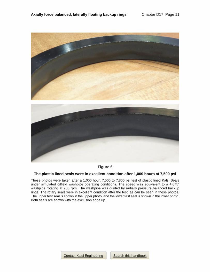
Figure 6
The plastic lined seals were in excellent condition after 1,000 hours at 7,500 psi
These photos were taken after a 1,000 hour, 7,500 to 7,800 psi test of plastic lined Kalsi Seals under simulated oilfield washpipe operating conditions. The speed was equivalent to a 4.875” washpipe rotating at 200 rpm. The washpipe was guided by radially pressure balanced backup rings. The rotary seals were in excellent condition after the test, as can be seen in these photos. The upper test seal is shown in the upper photo, and the lower test seal is shown in the lower photo. Both seals are shown with the exclusion edge up.

Axially force balanced, laterally floating backup rings Chapter D17 Page 12
Contact Kalsi Engineering Search this handbook
Testing for RCD sealing conditions in a 2.75” fixture
We have completed 200 and 300 hour tests of -303 extra wide plastic lined Kalsi Seals
mounted in a floating backup ring assembly simulating the extrusion gap clearance that is
obtainable in an oilfield rotary control device (RCD).
The seals were tested with 3,000 psi (20.68 MPa) lubricant pressure and 0.010”
(0.25mm) dynamic shaft runout, FIM. The speed was 750 rpm on a 2.75” (69.85mm) shaft,
which is equivalent to 200 rpm on a 10.375” (263.53mm) shaft. At 750 rpm, however, the
2.75” test fixture subjects the rotary seals to 3.75 times more runout cycles, compared to a
10.375” shaft at 200 rpm. The seals were tested with an ISO 150 viscosity grade synthetic
lubricant that was maintained at 200°F (93.33°C).
Testing 4.50” seals at ~10,000 psi with floating backup rings
A pair of 4.50” (114.30 mm) PN 682-7-318 Type F seals supported by floating backup
rings were tested for 6.5 hours at 24 rpm with a lubricant pressure of 9,800 psi (67.57
MPa). The test was designed to replicate the operating conditions of an oilfield cementing
swivel. The seal lubricant was an ISO 68 viscosity grade synthetic lubricant. Because of
the interfacial lubrication provided by the Kalsi Seals, the bulk lubricant temperature did
not exceed 96°F (35.6°C), and the seals were in excellent condition after the test.