Embed Size (px)
Citation preview

AWS 900 V4 SOFTWAREOWNER’S MANUAL

Page 2 AWS 900 V4 Software
Solid State LogicBegbroke, Oxford, England OX5 1RU • +44 (0)1865 842300
320 West 46th Street, 2nd Floor, New York, NY 10036, USA • +1 (1) 212 315 11113700 Wilshire Blvd, Suite 720, Los Angeles, CA 90010, USA • +1 (1) 213 249 92293-55-14 Sendagaya, Shibuya-Ku, Tokyo 151-0051, Japan • +81 (0)3 5474 1144
7 bis, rue de la Victoire, le Blanc Mesnil, Paris 93150, France • +33 (0)1 48 67 84 85Via Timavo 34, 20124 Milano, Italy • +39 (0)39 2328 094
Visit SSL at http://www.solidstatelogic.com
82BA1M0SB
© Solid State LogicAll Rights reserved under International and Pan-American Copyright Conventions
Solid State Logic, SSL, AWS 900, AWS 900+ SE, AWS 924, AWS 948and Total Recall are trademarks of Solid State Logic
All other trademarks are the property of their respective owners
No part of this publication may be reproduced in any form orby any means, whether mechanical or electronic, without thewritten permission of Solid State Logic, Oxford, England
Initial release March 2011
As research and development is a continual process, Solid State Logic reserves the rightto change the features and specifications described herein without notice or obligation.
E&OE

AWS 900 V4 Software Page 3
IMPORTANT INFORMATIONThis section contains definitions, warnings, and practical information necessary to ensure a safe working environment. Pleasetake time to read this section before installing or using your AWS. Please do not dispose of these instructions.
Graphic SymbolsThe following symbols may be used in this section and elsewhere in this manual:
General Hazard (refer to User or Service Instructions for details)
Electrical Hazard
General Safety• Read these instructions.
• Keep these instructions.
• Heed all warnings.
• Follow all instructions.
• Do not use this apparatus near water.
• Do not expose this apparatus to rain or moisture.
• Clean only with dry cloth.
• Do not block any ventilation openings. Install in accordance with the manufacturer’s instructions.
• Do not install near any heat sources such as radiators, heat registers, stoves or other apparatus (including amplifiers)that produce heat.
• Ensure that this apparatus is positioned on a secure level surface.
• Ensure that no strain is placed on the cables connecting to this apparatus. Ensure also that such cables are not placedwhere they can be stepped on, pinched, pulled or tripped over in any way.
• Refer all servicing to qualified personnel. Servicing is required when the apparatus has been damaged in any way, suchas power-supply cord or plug is damaged, liquid has been spilled or objects have fallen into the apparatus, the apparatushas been exposed to rain or moisture, does not operate normally or has been dropped.
• Adjustments or alterations to this apparatus may affect the performance such that safety and/or international compliancestandards may no longer be met.
• This apparatus is equipped with a headphone socket – excessive sound pressure from earphones and headphones cancause hearing loss.
• This apparatus is designed for use solely by engineers and competent operators skilled in the use of professional audioequipment.
Caution
The AWS console is too heavy for one person to lift. If covers or panels are removed for any reason, sharp
edges may be present on exposed metalwork.
To reduce the risk of fire or electric shock, do not expose this apparatus to rain or moisture.
To reduce the risk of electric shock, do not perform any servicing unless you are qualified to do so.
Introduction

Power Safety
• This apparatus includes a universal power supply; approved and certified for operation in this apparatus.
• An external disconnect device is required for this apparatus. The appliance coupler is a suitable disconnect device.
• The appliance coupler shall remain readily operable.
• Use only the Solid State Logic provided power cords. Use of any other power cord is not covered by your warrantyand may cause fire or explosion.
• The power cord must be earthed and precautions should be made so that the grounding is not defeated.
• Do not defeat the safety purpose of the polarised or grounding-type plugs fitted to the power cords. A polarised plughas two blades with one wider than the other. A grounding type plug has two blades and a third grounding prong. Thewide blade or the third prong are provided for your safety. If the provided plug does not fit into your outlet, consult anelectrician for replacement of the obsolete outlet.
• To ensure safe operation of this apparatus, connect only to an ac. power source that contains a protective earthing (PE)conductor. This apparatus is designed for connection to single phase supplies with the neutral conductor at earthpotential – category TN or TT – and is fitted with a protective fuse in the live conductor only. This apparatus is notdesigned for use with live and neutral connections reversed or where the neutral conductor is not at earth potential(IT supplies). This apparatus should not be connected to a power system that switches open the return (neutral) leadwhen the return lead also functions as the protective earth (PE).
• An external over-current protection device is required to protect the wiring to this apparatus which must be installedaccording to current wiring regulations. In certain countries this function is supplied by use of a fused plug. In other casesa fused spur or circuit breaker should be used according to local practice.
• If an extension power cable or adaptor is used, ensure that the total power rating of the power cable and/or adaptor isnot exceeded.
• Unplug this apparatus during an electrical storm or when unused for long periods of time.
• Do not operate this apparatus whilst it is covered or boxed in any way.
• To reduce the risk of electric shock, do not perform any servicing unless you are qualified to do so.
• Disconnect the power cord before removing any panels. The power switch alone does not provide adequate isolationfor service access.
• Do not permit anyone to remove panels or covers from this apparatus, other than qualified service personnel.
• Do not permit anyone other than qualified service personnel to operate this apparatus unless all panels and covers arein place.
Page 4 AWS 900 V4 Software
Introduction

AWS 900 V4 Software Page 5
Caution
When installing or servicing any item of SSL equipment with power applied, when cover panels are removed:
HAZARDOUS CONDITIONS CAN EXIST!
These hazards include: • High energy stored in capacitors
• High currents available from DC power busses
• Hot component surfaces
• High voltages
To reduce the risk of fire, replace internal fuses only with identical type and rating.
FCC NoticeThis equipment has been tested and found to comply with the limits for a Class A digital device, pursuant to part 15 of the
FCC Rules. These limits are designed to provide reasonable protection against harmful interference when the equipmentis used in a commercial environment. This equipment generates, uses, and can radiate radio frequency energy and, if notinstalled and used in accordance with the instruction manual, may cause harmful interference to radio communications.Operation of this equipment in a residential area is likely to cause harmful interference in which case the user will berequired to correct the interference at his own expense.
Disposal of WEEE by Users in the European UnionThe symbol shown here is on the product or on its packaging, which indicates that this product must not bedisposed of with other waste. Instead, it is the user’s responsibility to dispose of their waste equipment by handingit over to a designated collection point for recycling of waste electrical and electronic equipment. The separatecollection and recycling of your waste equipment at the time of disposal will help to conserve natural resourcesand ensure that it is recycled in a manner that protects human health and the environment. For more information
about where you can drop off your waste equipment for recycling, please contact your local city office, your household wastedisposal service or where you purchased the product.
Standards ConformanceThis apparatus fully conforms with the current protection requirements of the European community councildirectives on EMC and LVD.
Introduction
This page is intentionally blank
Page 6 AWS 900 V4 Software
Introduction

AWS 900 V4 Software Page 7
MANUAL CONTENTS
Important Information 3Graphic Symbols 3General Safety 3Caution 3Power Safety 4Caution 5FCC Notice 5Disposal of WEEE by Users in the European Union 5Standards Conformance 5
Manual Contents 7
Introduction 9Introduction to the AWS V4 Software 9Console Software Installation 9DAW Connection 10
AWS900 V4 Tutorial 11Introduction 11900 Channel Strip 13Centre Section 15
Console Operations 19Introduction 19Communications 21Console Setup Menu 22
DAW Control 25Introduction 25Configuring DAW Layers 27A-FADA Analogue Automation 29HUI and MCU Common Features 31Pro Tools HUI Control Guide 33HUI Plug-In Control 45Additional HUI Displays 48HUI Automation 51MCU (Mackie Control) Emulation 53
Total Recall 67Selecting TR Setups 68Matching the Console to the TR 69Additional TR Functions 72Total Recall via Logectivity 73
Introduction

Automation 75Automation Management via the Remote 76Operation 77Join and Revise 81Selecting Protection 83Automation Options 85Automation Setup Options 88Fader Links 89Pro Tools Setup Notes 90MIDI SysEx Load 93
The Remote Browser 95Introduction 95Connecting the Remote to the Console 96The Projects Tab 98The Mixes Tab 100The Total Recall Tab 101The Channels Tab 102The Externals Tab 103The About Tab 104
Page 8 AWS 900 V4 Software

AWS 900 V4 Software Page 9
INTRODUCTION
INTRODUCTION TO THE AWS V4 SOFTWARELaunched in 2004, the AWS (Analogue Workstation System) reinvented the professional production console by combiningclassic SSL Superanalogue™ console technology with comprehensive DAW control hardware in a single work surface.Over 550 consoles later the AWS is now used by leading international recording artists, producers and engineers and hasshaped expectations for session workflow within today’s and indeed tomorrow’s production environments.
Designed for mid scale commercial recording and production facilities, the AWS features a compact 24 fader frame. TheAWS delivers pristine SuperAnalogue™ mixing, 24 ultra-clean SSL SuperAnalogue mic pre’s, classic SSL dual curve EQ onevery channel, two assignable SSL Dynamics, legendary Stereo Buss Compressor, TotalRecall™ and full 5.1 monitoring. Inaddition to on board classic SSL Automation, both models also feature the revolutionary new A-FADA mode wheremotorised analogue faders follow DAW Automation data.
The AWS also features Ethernet connectivity for streamlined hardware control of your Digital Audio Workstation, deliveringelegant, ergonomic physical control over your entire studio environment with dedicated heavy duty DAW transport, V-Potmultifunction encoders with position indicating LED’s, Digital Scribble Strips, DAW fader mode, global and channel routingcontrol and built-in TFT display for advanced plug-in editing. Project Session Management is kept simple through SSL’sproprietary Logictivity interface.
The AWS is an SSL SuperAnalogue™ console, featuring the audio performance specifications that have established thebenchmarks by which other manufacturers are measured. Exceptionally low THD, noise floor & crosstalk levels keep youraudio absolutely pristine, while our legendary headroom carries every nuance of your audio and allows engineers to mix‘hotter’ without distortion.
While the AWS offers a powerful large format analogue console feature set within a compact console design, it also goesfurther than any other analogue console by integrating seamlessly into a DAW-based facility by incorporating hands-oncontrol of important recording, routing, mixing, and editing functions in all major DAW applications including Pro Tools™,Logic Audio™, Nuendo™, Sonar™ and many others.
Now, once again, the AWS console series is enhanced by a significant software release. You will find many new featuresincluding:
• A-FADA, analogue fader accesses DAW Automation
• Enhanced Logectivity remote browser
• “SET” Function allows a selection of channels to be changed in unison
• Enhanced EFX system
• “Show Links” in automation system
• Improved DAW support for dual work stations
• Advanced Talkback system
• “Solo Boost” and “Isolated AFL” features
CONSOLE SOFTWARE INSTALLATIONPlease refer to the software installation instructions provided with your software upgrade package.
Introduction

DAW CONNECTIONThe AWS console communicates with a DAW directly via Ethernet or via three MIDI ports. To use the Ethernet option athird party ipMIDI software driver must be installed on the DAW computer. Registered owners can download this fromthe SSL website: www.update.solidstatelogic.com. Using these methods of communication allows the AWS to beused with a wide variety of DAW applications on a wide variety of platforms. The AWS uses Mackie control or a ‘HUI’compatible protocol, and so any DAW program that can be configured to use three HUI devices can access the full powerof the AWS.
Please refer to your DAW manual for details on how to configure the DAW application for AWS under Mackie or HUIcontrol.
OverviewIn normal operation the AWS uses an Ethernet connection for DAW control and the SSL AWS Remote for sessionmanagement. The next section describes how to download and install the ipMIDI driver and AWS Remote on Macintoshand PC.
Optionally the AWS can use a standard MIDI connection between the AWS console and your DAW using a multi port MIDIinterface. In this mode only one DAW layer can be configured. The console communicates with the DAW via the MIDI portslocated on the rear of the console – details are provided at the end of this section.
Installing the ipMIDI driver and AWS RemoteDownload on to your workstation computer either the AWS900SE_Mac_Support.dmg disk image (Macintosh) or theAWSxxx.zip file (Windows). These contain the AWS Remote and ipMIDI applications and the latest version of the installationinstructions:
www.update.solidstatelogic.com/support/consoles/aws/downloads.asp
System Requirements for your workstation computer: AWS Remote is a Java application. It will run under Java Version 5or higher. ipMIDI is compatible with Windows 2000 (maximum 9 MIDI ports), XP, Vista and Windows 7, and MacintoshOS X 10.4 upwards.
Software Installation (Macintosh)
Mount the AWS900SE_Mac_Support.dmg disk image and open it.
AWS Remote: Double-click on the AWS Remote application to install.
ipMIDI: Double click on the ipMIDI.pkg file to run the installation program. Note that you will be asked to log out and inagain once you have completed the installation. Once you have logged back in open Audio MIDI Setup, select the MIDI taband double click on the ipMIDI icon. Set the number of MIDI ports to 10 in the resulting pop-up.
If you are upgrading an older copy of ipMIDI you must uninstall it before running the installer. To uninstall ipMIDI simplydelete: </Library/Audio/MIDI Drivers/ipMIDIDriver.bundle>. You should empty the Trash after deletingthe bundle file before running the installer.
Page 10 AWS 900 V4 Software
Introduction

AWS 900 V4 Software Page 11
Software Installation (PC)
Open the AWS900SE_Win_Support.zip archive.
AWS Remote: Double click on AWSRemote.exe to install the program.
ipMIDI: Run the setupipmidi_1.8.exe application (note that the last part of the name may change depending on the versionyou are installing) by double clicking on it. Note that you will have to restart the computer at the end of the setup process.Once the computer has restarted right click on the ipMIDI icon in the task bar and set the number of MIDI ports to 10 inthe resulting pop-up.
If you are upgrading an older copy of ipMIDI you must uninstall it (using Add/Remove programs) before running the installer.
Introduction

Page 12 AWS 900 V4 Software
Introduction
This page is intentionally blank
AWS 900 V4 Software Page 13
AWS 900 V4 TUTORIAL
INTRODUCTIONThis tutorial aims to provide an operational overview of the AWS console, highlighting the ways in which it is differentfrom other consoles with which operators may be familiar.
The tutorial provides an overview of typical studio configurations, mode selection and both the channel strip and CentreSection controls.
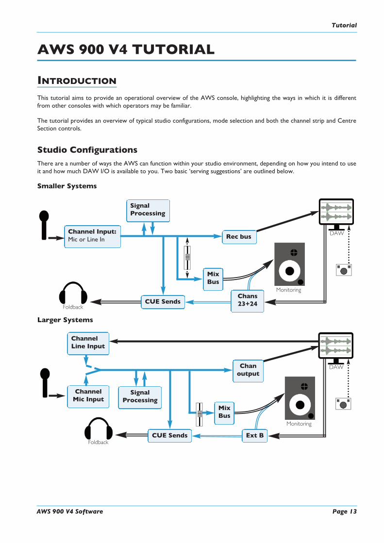
Studio ConfigurationsThere are a number of ways the AWS can function within your studio environment, depending on how you intend to useit and how much DAW I/O is available to you. Two basic ‘serving suggestions’ are outlined below.
Smaller Systems
Larger Systems
DAW
ChannelMic Input
CUE Sends Ext B
Monitoring
Chanoutput
SignalProcessing
ChannelLine Input
Foldback
MixBus
DAWChannel Input:Mic or Line In
CUE Sends
Monitoring
Foldback
Rec bus
SignalProcessing
MixBus
Chans23+24
Tutorial
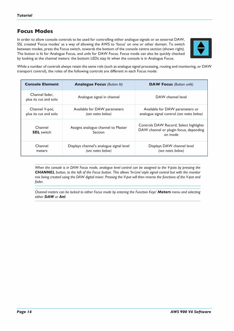
Focus ModesIn order to allow console controls to be used for controlling either analogue signals or an external DAW,SSL created ‘Focus modes’ as a way of allowing the AWS to ‘focus’ on one or other domain. To switchbetween modes, press the Focus switch, towards the bottom of the console centre section (shown right).The button is lit for Analogue Focus, and unlit for DAW Focus. Focus mode can also be quickly checkedby looking at the channel meters: the bottom LEDs stay lit when the console is in Analogue Focus.
While a number of controls always retain the same role (such as analogue signal processing, routing and monitoring, or DAWtransport control), the roles of the following controls are different in each Focus mode:
When the console is in DAW Focus mode, analogue level control can be assigned to the V-pots by pressing theCHANNEL button, to the left of the Focus button. This allows ‘In-Line’-style signal control but with the monitormix being created using the DAW digital mixer. Pressing the V-pot will then reverse the functions of the V-pot andfader.
Channel meters can be locked to either Focus mode by entering the Function Keys’Meters menu and selectingeither DAW or Anl.
Console Element Analogue Focus (Button lit) DAW Focus (Button unlit)
Channel fader,plus its cut and solo
Analogue signal in channel DAW channel level
Channel V-pot,plus its cut and solo
Available for DAW parameters(see notes below)
Available for DAW parameters oranalogue signal control (see notes below)
ChannelSEL switch
Assigns analogue channel to MasterSection
Controls DAW Record, Select highlightsDAW channel or plugin focus, depending
on mode
Channelmeters
Displays channel’s analogue signal level(see notes below)
Displays DAW channel level(see notes below)
Page 14 AWS 900 V4 Software
Tutorial

AWS 900 V4 Software Page 15
900 CHANNEL STRIP
Input configurationSelect the Mic or Line input by pressing FLIP and adjust the input gain using theappropriate gain pot. The signal level is shown in the meter bridge above the channel.
Signal ProcessingDynamicsAny channel can make use of the two compressor/gate modules housed within the AWScentre section. Press the 1 or 2 button at the bottom of the meter bridge to insert oneof them into the channel path.
Dynamics cannot be assigned if they are already being used by another channel.
The IN button at the bottom of the compressor/gate module switches it into circuit.
Filter and EQThe filter and EQ are both switched in using the EQ IN switch. Turn the HPF pot upfrom minimum to activate the filter – the EQ IN goes from red to green to indicate thatthe filter is active.
The EQ has four bands, each with a gain control pot labelled ‘dB’ and frequency control,and the mid bands have Q control. Press the HF and LF bands’ BELL buttons to switchfrom shelf to bell shape.
Insert PointTo switch the channel insert into circuit, press the INS IN switch in the centre of theEQ section. Press PRE to place it before the EQ in the processing chain.
RoutingCue, FX and EFX SendsTo activate the Cue or FX sends, press on its gain pot and turn up the gain. The Stereo Cue signal isnormally sourced pre-fader – to move it to after the fader, press POST. The stereo cue also has a pancontrol.
There are two stereo cue busses and four FX busses. Each channel can feed one of the stereo cue bussesand two of the FX busses (FX1 or 3, FX2 or 4). Any send can instead control the EFX system, which usesauxiliary sends to control the level of the channel’s feed to the track busses or direct output – use theCUE B, FX3, FX4 and EFX switches to select between sends.
Bus Routing
To route channels to the Record and Mix busses, press the REC and/orMIX switch to the right of thechannel pan pot.
Use the eight numbered switches immediately underneath the channel meters (shown above right) toroute to the track busses. By default, signals are sent post-fader. To source the send pre-fader or post pan-control, press the PRE or PAN switches beneath the track bus selection switches.
Tutorial

Channel PanningThe pan pot towards the bottom of the channel strip is used to adjust the stereo position of signals being sent to the Recordand Mix busses, as well as to the Track busses when they are functioning in stereo.
Level, Cuts and SolosThe channel fader controls the channel send to the Rec and Mix busses, as well as any other sends which are operating post-fader. Use the CUT and SOLO switches below the digital display to mute or solo the signal assigned to the fader.
Cue, FX and EFX SendsThe area below the EQ controls the channel’s send to the console’s two stereo cue busses and four FX busses. Each channelcan feed one of stereo cue busses and two of the FX busses (FX1 or 3, FX2 or 4). Alternatively, the send controls for oneof the busses can be assigned to the EFX system, which enables greater routing flexibility from the AWS channels byemploying redundant auxiliary sends to control the level of the channel’s feed to the track busses or direct output.
To activate the Cue or FX sends, press on its gain pot (the ON LED to the pot’s right will light) and turn up the gain. TheStereo Cue signal is normally sourced pre-fader – to move it to after the fader, press POST.
The stereo cue’s blue pan pot can be used to pan the channel send to the stereo bus.
By default, CUE A, FX1 and FX2 are active. To switch from CUE A to CUE B, FX1 to FX3 or FX2 toFX4, press the CUE B, FX3 and FX4 switches beside the relevant gain pot.
To use any bus send control to feed the EFX system, press the EFX button beside the relevant gain pot.That gain pot will now allow you to adjust the level being sent to any active track busses or, if the EFXCFunction key is active, the channel direct output.
The EFX LED will light to indicate that EFX is active, and the DIRECT PRE/EFX LED lights greento indicate that the channel output has been assigned to the EFX.
When the SET Function key is selected, pressing any in-channel non-latching switches (such as an FX activation switch)will cause that switch to activate in all selected channels
Only one auxiliary send control from each channel may feed the EFX system.
Page 16 AWS 900 V4 Software
Tutorial

AWS 900 V4 Software Page 17
Direct OutputBy default, the channel direct output is sourced post-fader. To source it pre-fader, press theDIRECT PRE/EFX switch,located above the CUE ST gain pot.
Direct Outputs and EFXThe EFX system allows redundant auxiliary send controls to be used to control the channel’s send to the direct output. Toemploy EFX for any channel, select the auxiliary send control which is least likely to be needed in the channel (Stereo Cue,FX1 or FX2), and assign it to the EFX system:
Press the EFX button beside the gain pot. The EFX LED will light and the selected gain pot will now control allow you toadjust the Channel output level.
Press the EFXC Function key to switch the channel’s EFX send from the Track bus to the Channel output. TheDIRECT PRE/EFX LED in the channel strip lights green to indicate that the channel output has been assigned to theEFX.
Note also that only one auxiliary send control from each channel may feed the EFX system – if a second auxiliary sendis assigned to EFX within the same channel, it will replace the originally assigned auxiliary.
Track Bus RoutingChannel signals can be routed to the track busses using the eight numbered switches immediatelyunderneath the channel meters. By default, signals are sent post-fader. To source the send pre-fader orpost pan-control, press the PRE or PAN switches beneath the track bus selection switches. When thesource is post-pan, the odd-numbered track busses receive the left component, and the even-numberedbusses receive the right component.
Note that the Track busses are designed for external tracking and not for internal sub-grouping – theycannot be routed to the Mix and Rec busses.
Track Busses and EFX:The EFX system allows redundant auxiliary send controls to be used to control the channel’s send to theTrack busses. To employ EFX for any channel, select the auxiliary send control which is least likely to beneeded in the channel (Stereo Cue, FX1 or FX2), and assign it to the EFX system:
Press the EFX button beside the gain pot. The EFX LED will light. Check that the EFXC Function key isnot pressed as this employs the EFX on the direct channel output not the track busses.The selected gainpot will now allow you to adjust the level being sent to any active track busses.
Note that only one auxiliary send control from each channel may feed the EFX system – if a second auxiliary send isassigned to EFX within the same channel, it will replace the originally assigned auxiliary.
Tutorial

CENTRE SECTION
Adjusting the Mix and Record BussesTo assign control of the Record and/or Mix busses to the master fader, hold down the buttonat the base of the RECORD orMIX columns of the bussing matrix next to the fader, andpress the button in the row labelled FADER. Now move the master fader to adjust the buslevel.
Creating a Monitor MixPress MIX in the MON SRC buttons monitor source buttons on the Monitor ControlPanel and ensure that the CUT button is inactive. Adjust the monitor level using the mainmonitor level pot.
Creating Foldback MixesFoldback mixes can be quickly created using the Foldback section of the centre section.
Select sources using the buttons down the right-hand side. TheMIX pots control level for the sources totheir right. There is also an overall LEVEL control.
Using the FX ReturnsExternal FX processing such as reverbs and delays can be connected to the console’s four FX send busses.FX unit outputs can be returned back into the AWS via the four Stereo Return inputs in the console centresection. These can be routed to either of the foldback mixers, and to the record and mix busses.
Using TalkbackThe talkback controls are located to the right of the shuttle wheel. Press SLATE to sendtalkback to the Mix, Rec and Track busses, press FB A or B to send it to the foldbacks, orpress TB ALL to send it to all outputs. The black pots above the TFT screen controlcommunications levels.
‘In-line’ RecordingSelecting CHANNEL on the Master Control Panel while in DAW Focus will allow you to control the input levels fromthe channel rotary encoders and the DAWmix from the channel faders. Pushing the Channel Rotary Encoder will swap theencoder and fader, which allows some faders to control input level and others to control the DAWmonitor mix, mimickingthe operation of an in-line console.
Page 18 AWS 900 V4 Software
Tutorial

AWS 900 V4 Software Page 19
CONSOLE OPERATIONS
INTRODUCTIONThe console’s centre section is used to control the console busses, dynamics, monitoring and overall configuration as wellas providing access to a number of DAW control elements.
Power Supply IndicatorsBeneath the VU meters, on the main control surface, you will find a row of four LEDs that display the current state of powerrails within the console. The ±15 Volt and the +4 Volt supplies are for analogue audio and logic circuitry respectively. The+12 Volt supply provides power for the faders and some relays. All LEDs should be lit whenever the console is poweredup. If any are unlit, please call your technical department! If you don’t have one, please refer to the maintenance informationin the appendices of this manual.
Function KeysA number of console elements are configured using the Function keys, locatedin the top right quarter of the monitor panel. The top row of buttons assign asubset of softkeys to the lower row of buttons. The display indicates thefunction assigned to the lower row. Frequently, the lower softkeys are alsosubmenus, opening up a further set of softkeys in the lower row of buttons.
When none of the upper row of keys are selected, the following functions are applied to the lower softkeys:
ALL Activates the SEL key on all channel strips.
SET Groups the controls of all channels with their SEL key activated. With SET enabled, pressing any momentaryswitch on any selected channel will cause the switch action to be replicated across all selected channels.
0dB Sets selected faders to 0dB
EFXC (Only available when EFX is active) Switches the channel’s EFX send from the Track bus to the Channeloutput. The DIRECT PRE/EFX LED in the channel strip lights green to indicate that the channel outputhas been assigned to the EFX.
Operation

COMMUNICATIONSThe main communications controls (talkback etc.) are located tothe right of the shuttle wheel at the bottom of the console (seeleft).
There is a built-in talkback microphone ( ) located in theutilities section above the TFT screen.Level controls for the communications are found here (see right).
Note that a gain control for the talkback mic preamp is provided on the connector panel adjacentto the external talkback output jack. An external talkback mic may be connected to the console’stalkback distribution circuitry via an XLR on the connector panel. When using this facility, turn the console mic preampgain to minimum unless you want the console mic to contribute to the talkback system.
The SLATE button interrupts the Record, Mix and Track bus outputs with talkback. The utilities sectionSlate pot controls the level of the talkback mic feed to these busses.
The F/B A and F/B B buttons inject talkback onto Foldback outputs A and B respectively, after the leveland cut controls. The utilities section TB to Foldback pot controls the level of the talkback mic feed tothe Foldbacks.
Note that the TB to FB option in the Setup menu defines whether talkback sums with or replaces the normalfoldback signal. (See below)
The EXT T/B button injects talkback to the external talkback send, via a 6.35mm jack on the connectorpanel. Talkback Out controls this level.
An external ‘listen’ mic signal can be connected via an XLR on the centre section connector panel, and isusually placed in the recording area. The LISTEN button injects this mic signal onto the Mini A loudspeakerfeeds, and dims the main loudspeakers. The LISTEN pot controls the mic level.
The circuitry features SSL’s legendary listen mic compressor, the sound of which is much loved by manyexperienced SSL users, and so the connector panel provides a post compressor output jack – ‘Listen MicOut’.
Note that the SLATE button cuts the monitors, and the other talkback buttons dim the monitors.
RED LIGHT provides an isolated contact closure for hooking up to a studio red light via an external relaybox. This function can be fired from a GPI input.
TB ALL feeds the talkback mic to the foldback sends and the external talkback output.
Note: The talkback switch functions are all duplicated on the Talkback/GPIO connector on the rear of the console asare the monitor CUT and DIM switches.
6
5
4
3
2
1
7
1
2
4
36
5 14
7
23
Page 20 AWS 900 V4 Software
Operation

AWS 900 V4 Software Page 21
Communications Setup OptionsFurther Talkback, Listen and Red Light communication options are accessed via the TFT screen. The 16 boxes at the baseof the screen indicate the functions assigned to the 16 buttons in two rows of eight below the screen. Press the SSL button,followed byMisc > Setup and locate the following options in the list:
Talkback switches are: Select the operation of the talkback buttons: Momentary / Latching / Auto(Play) / Auto (Record).
Listen switch is: Select the operation of the Listen buttons: Latching / Auto (Play) / Auto(Record).
Red light switch is: Select the operation of the Red Light switch: Manual / Auto (Play) / Auto(Record).
TB switches disable Listen: This allows the Listen function to be switched off when talkback is activated,thus avoiding feedback problems.
TB to FB: (Sums / Replaces) When assigning talkback to foldbacks, this option defineswhether talkback sums with or replaces the normal foldback signal.
The ‘Auto’ modes inhibit the Talkback and/or Listen switches when the transport Play or Record tally is lit. Selecting redlight to one of ‘Auto’ modes makes it follow the Play or Record tally.
OscillatorThe ‘oscillator’ is in fact a comprehensive tone and pink noise generator. It is located above the TFT screen, containscontrols for frequency, level and routing of tone or pink noise to the Mix, Record and Track bus outputs and to the monitoroutputs for use in monitor calibration.
OSC ON activates the oscillator output (surprise, surprise!). It’s good practice to turn theoscillator off when recording, to prevent any accidental routing to desk outputs.
PINK ON switches the output from tone to pink noise. Note that the pink noise level canonly be adjusted using the Pink ‘Cal’ preset.
LEVEL This pot adjusts the level of the tone generator from -25dBu to +20dBu. Whenfully anticlockwise, a preset ‘Cal’ level is selected which can be calibrated usingthe multi-turn presets located below the level control; a red LED lights to showwhen the level control is in the calibrated position.
FREQ This rotary switch provides six preset frequencies.
The oscillator may be routed to the TRACK busses, theMIX bus and the REC bus (individually or simultaneously) usingthe switches to the right of the LEVEL pot.. The oscillator output is also available on an XLR on the centre sectionconnector panel.
Operation

CONSOLE SETUP MENU
The centre section TFT screen provides access to a setup menu that holds a number of useful console-related items. SelectSSL followed byMisc and then Setup.
To change a setting, use the left hand V-pot ( ) to select the item, then press the V-pot to enter adjustment mode.Turn the V-pot to the desired setting and press it a second time to save the setting.
The Setup options are described over the following pages.
1
Misc
Setup
SSL
(blank)
(blank) Restart
1
Page 22 AWS 900 V4 Software
Operation

AWS 900 V4 Software Page 23
OperationOperation
AutomationGlide frames: Sets the ramp time in frames for the automation SNAP mode. (range 0 - 255)
Rollback threshold frames: Sets the number of consecutive frames that the system needs to see todetermine if a Rollback has taken place. The range is 2 - 10; the default is 2.Increase as required if a Rollback occurs when you stop the timecode master.
In Mix show: When using the automation, you have a choice of what is displayed on theconsole’s channel scribble strips (and below the Group and Master faderlevels in the Centre Section TFT screen). The choices are:
Automation Mode: displays the status of the faders – Auto, Safe or Manual;
Channel names in Mix running: displays the channel names once Execute ispressed in automation,
Channel names: displays the channels names regardless.
Latched Match and Play (ON/OFF) Normally Match and Play are automatically deselected after a Cutswitch is operated. This option latches the Match or Play function untildeselected manually.
TalkbackTalkback switches are: Select the operation of the talkback buttons: Momentary / Latching / Auto
(Play) / Auto (Record).
Listen switch is: Select the operation of the Listen buttons: Latching / Auto (Play) / Auto(Record).
Red light switch is: Select the operation of the Red Light: Manual / Auto (Play) / Auto (Record).
TB switches disable Listen: This allows the Listen function to be switched off when talkback is activated,thus avoiding feedback problems.
TB to FB: (Sums / Replaces) When assigning talkback to foldbacks, this option defineswhether talkback sums with or replaces the normal foldback signal.
Monitor SectionMonitor Gain Display: The calibration of the main monitor Gain pot and display can be set to one
of three industry-standard monitoring modes: Music (Off to 11) / Film (Offto 95dB) / Gain (Off to 0dB)
Monitor Set CAL level: When in Film mode, adjust the calibrated listening level: 70 - 90 (dB).
SeeMonitor Level Display and Calibrated listening level for more details of these options
Solo Gain boost: Automatically increases the monitor level when a SOLO or AFL is activated(Range: 0-10dB).
Isolated channels AFL on solo: Set solo-isolated channels to automatically solo in AFL (ON/OFF).

Desk SetupInput Cut Enable: If set ON, the channel strip CUT button will cut prefade sends, ie. Aux and
CHOP sends (ON / OFF).
Analogue Meter Scaling: Set the analogue level corresponding to 0dBfs on the console meters. (Range18, 20, 22, 24 dBu).
DAW setupDAW setup parameters can be found later in this manual.
Desk settingsScribble Strip Brightness: Use this to adjust the channel scribble strip brightness (range: 1-6)
Turn Off Display After: Shuts off the TFT display after a predetermined time: 30 mins to 5 hours in30 minute increments.
The scribble-strip displays can be turned off by turning the control pot clockwise (beyond 8 or 6) to ‘Off’.
This feature is dependent on your scribble strip type and will not be available on original 900 consoles.
On occasion, when changing the status of some of the above functions, you will be prompted to reboot your AWS console.It is possible to do this without reaching the Power switch at the rear of the console through the addition of a soft menuRESTART. When you select this you will be prompted to CONFIRM and your console will reboot.
Page 24 AWS 900 V4 Software
Operation

AWS 900 V4 Software Page 25
DAW CONTROL
INTRODUCTIONWhen connected to a Digital Audio Workstation which supports either the HUI or Mackie Control Universal (MCU)protocols, the AWS becomes a powerful digital work surface controller, giving direct access to the most important controlswithin the DAW. The console faders can be used to control the workstation faders and sends, the 24 channel V-pots canbe used to control pans, sends and I/O functions and the Master Control Panel and plug-in controller provide easy accessto a range of other parameters.
Provided the Logictivity option has been enabled the AWS can control two DAWs simultaneously from two virtual ‘layers’.
For an up to date list of compatible DAW applications please go to the AWS support pages at http://www.solidstatelogic.com- Pro Tools and a number of other DAWs support the HUI protocol.
- Many other DAWs, including Logic Audio, Sonar, Nuendo and Digital Performer, support the MCU protocol.
Please refer to the controller documentation that came with your DAW
A-FADAA-FADA (Analogue Fader Accesses DAW Automation), is an innovative new way of combining the convenience of DAWautomation with the audio qualities of analogue mixing by using DAW track automation to control the analogue faders.
DAW Controller Features Summary• Direct access to all major DAW mixing, editing and automation parameters
• Direct control of plug-in settings
• Integral colour TFT display with dedicated control keys
• High resolution rotary encoder (V-pot) in every channel provides control of DAW pans, sends and I/O routing
• High quality motorised faders to write/replay level moves in your DAW
• Simple switching between console layer and DAW control layer
• Full remote control implementation
• Operation independent of platform or application
• DAW control of analogue faders using A-FADA
DAW Control

Focus ModesIn order to allow console controls to be used to control either analogue signals or an external DAW, SSLcreated ‘Focus modes’ as a way of allowing the AWS to ‘focus’ on one or other domain. To switch betweenmodes, press the Focus switch, towards the bottom of the console centre section (shown right). Thebutton is lit for Analogue Focus, and unlit for DAW Focus. Focus mode can also be quickly checked bylooking at the channel meters: the bottom LEDs stay lit when the console is in Analogue Focus.
While a number of controls always retain the same role (such as analogue signal processing, routing and monitoring, or DAWtransport control), the roles of the following controls are different in each Focus mode:
When the console is in DAW Focus mode, analogue level control of stereo channels can be assigned to the V-pots bypressing the CHANNEL switch, to the left of the Focus button. This allows ‘In-Line’-style signal control but with themonitor mix being created using the DAW digital mixer. Pressing the V-pot will then cause the functions of the V-potand fader to be swapped.
Channel meters can be locked to either Focus mode by entering the Function Keys’Meters menu and selecting eitherDAW or Anl.
This section of the manual assumes that the console is in DAW Focus mode.
Console Element Analogue Focus (Button lit) DAW Focus (Button unlit)
Channel faders,plus its cuts and solos
Analogue signal in channel DAW channel level
Channel V-pots,plus its cuts and solos
In-line: Secondary path level; Stereo: BalanceOr DAW params (see notes below)
Available for DAW parameters oranalogue signal control (see notes below)
ChannelSEL switch
Assigns analogue channel to Master SectionHighlights DAW channel, track arm or
plug-in select
Channelmeters
Displays channel’s analogue signal level(see notes below)
Displays DAW channel level(see notes below)
Page 26 AWS 900 V4 Software
DAW Control

AWS 900 V4 Software Page 27
CONFIGURING DAW LAYERS
DAW LayersThe AWS can connect to two DAWs simultaneously which are controlled from the two virtual ‘layers’. Control operationsperformed on the AWS control surface will then affect whichever DAW is assigned to the currently selected layer. To selectwhich DAW is assigned to each layer go to SSL >Misc > Setup on your console and select the following:
MIDI Connects via: Network. Note that only one DAW layer is available when using the standardMIDI ports.
DAW 1: Protools HUI / Logic / Logic Handshake / Nuendo / Digital Performer / Sonar
DAW 2: Protools HUI / Logic / Logic Handshake / Nuendo / Digital Performer / Sonar/ None
If ‘None’ is selected for DAW 2, Menu entries related to DAW 2 will not appear.
Transport lock layer: Select the master DAW layer for transport control between DAW 1, DAW2 or Off.
First physical channel DAW 1: Select the console channel number that is controlling the first track numberon DAW 1.(When DAW 2 is assigned, there is a First physical channel DAW 2:menu entry.)
Channel Count DAW 1: Select the total number of channels dedicated to DAW control (8-24 in stepsof 8).(When DAW 2 is assigned, there is a Channel Count DAW 2: menuentry.)
Single Layer: Assign both DAWs to a single layer (ON/OFF).
Can only be set to ON if the two DAW layers are assigned to different channels.
After making these changes the console should be restarted.
Setup ipMIDI ports 1, 2 and 3 as the MIDI controller ports within the Primary DAW and ipMIDI ports 4, 5 and 6 as theMIDI controller ports within the Secondary DAW. See the end of Section 4 for more details as to the setup of each specificDAW.
When the desk is in DAW Focus, the console’s controls will only affect the DAW on the current layer. There are two waysto select which DAW layer is being controlled:
- In the TFT screen, activate SSL then press Daw and choose either DAW1 or DAW2.
- Press theMISC Function Key and choose either DAW1 or DAW2.
The transport controls can be locked to one layer using the Setup menu’s Transport lock layer entry – see above.
DAW Control

Communication with your DAWThe AWS connects to your chosen DAW via three MIDI ports at the rear of the console or via MIDI over Ethernet. EachAWS DAW layer emulates three HUI or MCU controllers. The HUI and Mackie Control (MCU) protocol are widelysupported by DAW manufacturers.
Refer to your DAW manual for information on how to configure your software. Once configured and connected,communication with the DAW will be initialised, and the level of the AWS channel faders, rotary controls and masterfunctions will be set to match the DAW controls (provided you are in DAW Focus mode and have the right DAW layerenabled).
When using your DAW without the AWS, you should remove the AWS from the MIDI controllers section of your DAW(please see the information specific to your DAW).
Logic HandshakingLogic Audio uses a challenge - response system to automatically detect connected controllers when it boots up. This featurecan be enabled by selecting ‘Logic Handshake’ when choosing the protocol type in SSL > Misc > Setup. Selecting anyother MCU protocol will disable this feature.
Page 28 AWS 900 V4 Software
DAW Control

AWS 900 V4 Software Page 29
A-FADA ANALOGUE AUTOMATIONA-FADA (Analogue Fader Accesses DAW Automation) is an innovative new way of integrating your DAW automationsystem with the audio qualities of analogue mixing by using DAW track automation to control the analogue faders and cutfunctions, opening up a wide range of possibilities for creativity and convenience in mix automation.
Operationally, A-FADA should quickly become intuitive to anyone who is familiar with their DAW automation system.With this in mind, the descriptions below provide enough information to get you going and solve the immediate challenges,but the rest is up to you.
A-FADA is enabled in the TFT screen by selecting SSL followed by Daw, and then selecting DF 1 or DF 2 (A-FADAcontrol from DAW Layer 1 or Layer 2). Alternatively, press the MISC button in the Function keys, and select DF 1 orDF 2 (A-FADA control from DAW Layer 1 or Layer 2).
Note that if only one DAW option is available, you have only set up one DAW layer in the console screen’s SSL >Misc> Setup menu.
The console’s analogue faders are controlled by the automation information from those DAW tracks assigned to channels1-24. The automation data is applied to the signal path assigned to the fader, regardless of whether it is mono or stereo. InInline Mix or Track and Analogue Focus mode the channel V-pot will control the secondary signal path but will not writeautomation to the DAW, allowing more audio channels to be passed through the console on mix-down if required. InDAW focus the channel V-pot controls the selected DAW parameter.
Once A-FADA mode has been enabled the console faders will control the 24 corresponding DAW faders and the faderposition signal from the DAW will control the console fader positions and analogue gain, regardless of the selected Focusmode.
In Analogue Focus the channel cut switches control the analogue cuts directly, and in DAW Focus they are controlled viathe DAW. This allows channels to be quickly muted without writing automation by selecting Analogue Focus.
The console solo switches are connected to the analogue signal path in both Focus modes.
In order to lock console channels to the same DAW track (and thus automation), Channel/Bank scrolling is disabled in A-FADA mode.
If you now play the DAW automation or move an on-screen fader, you will see the analogue faders move – these movementsare affecting the analogue signal levels within the AWS.
SnapThe Snap function, located within the Misc Function keys and within the TFT screen’s DAW menu, takes a snapshot ofthe console analogue fader positions when A-FADA mode is enabled. Pressing the Snap switch will move the faders to thestored positions, allowing the analogue balance to be restored and written to the DAW automation.
DAW Control

Setup GuidelinesWhen moving the faders, there is a good chance that you will be affecting the track output from the DAW and the channeloutput within the AWS simultaneously, thus duplicating all of the level changes – an effect which is probably unwanted.
There are a number of potential solutions to this duplication:
Solution 3: Use a dedicated DAW for analogue automationUse two DAW layers, one for your audio and one for your automation. This will require you to have two DAWs runningon either the same or two separate computers, and to enable both DAW layers within the console screen’s SSL >Misc> Setup menu.
A variation on this is possible with Logic, which allows two (or more) controllers to be configured. This allows one layerto be used as a normal DAW controller and the second to be locked to 24 dedicated automation tracks.
Micro-automation (such as the removal of undesirable transients) could be performed on the original audio tracks withinthe DAW by entering DAW Focus mode and scrolling to those tracks.
Solution 2: Create additional DAW tracks
This second option allows automation to be written independently for analogue and DAW channels.
Create 24 blank DAW tracks, and bank to appear on console channels 1-24. Select A-FADA.
If you have automation you wish to re-use, copy it from the audio tracks and paste it to the blank tracks you have justcreated. You will then need to either disable or delete the automation from the original tracks.
If the automation is deleted rather than disabled, micro-automation (such as the removal of undesirable transients) canbe performed on the original audio tracks within the DAW by temporarily disabling A-FADA and scrolling to thosetracks.
Note that MIDI tracks should not normally be used as the fader position is displayed as a controller value (0-127)rather than in dB.
Solution 1: Use pre-fade outputsThis first option would be suitable if you wish to replicate the DAW automation in the analogue domain:
Route DAW tracks from pre-fader to the appropriate analogue outputs. In Pro Tools this can be done using a prefaderaux send and setting the aux gain to 0dB. In Logic route an aux send to a different bus on each channel then route theaux sends to the appropriate analogue outputs. De-assign the track outputs to avoid summing pre and post fade signals.Within the DAW, fader movements will now only affect the Master bus and any other post-fader sends.
This also allows the creation of post fade aux sends within both the AWS and the DAW, providing some interestingcreative options.
Page 30 AWS 900 V4 Software
DAW Control
AWS 900 V4 Software Page 31
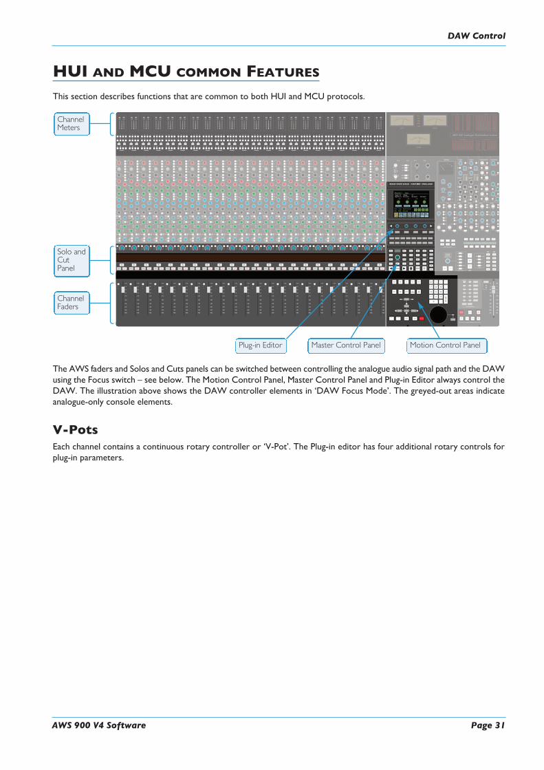
HUI AND MCU COMMON FEATURESThis section describes functions that are common to both HUI and MCU protocols.
The AWS faders and Solos and Cuts panels can be switched between controlling the analogue audio signal path and the DAWusing the Focus switch – see below. The Motion Control Panel, Master Control Panel and Plug-in Editor always control theDAW. The illustration above shows the DAW controller elements in ‘DAW Focus Mode’. The greyed-out areas indicateanalogue-only console elements.
V-PotsEach channel contains a continuous rotary controller or ‘V-Pot’. The Plug-in editor has four additional rotary controls forplug-in parameters.
ChannelFaders
ChannelMeters
Solo andCutPanel
Plug-in Editor Master Control Panel Motion Control Panel
DAW Control

The Master Control PanelThe Master Control Panel includes a mixture of master functions and modifier keys for control of a DAW. The layoutshown below is for HUI. Alternative layouts for the various MCU implementations are included later in this manual.
Channel Banking ControlsThe AWS console has 24 touch sensitive moving faders, however, if the DAW session has more faders than this, the AWScan ‘bank flip’ its faders to control any number of virtual faders within the DAW.
To flip the 24 console faders to the next set of 24 DAW faders, press the right bank button. To flip back to the previous24 faders press the left bank button. Any number of virtual faders can be controlled from the AWS using the bankingbuttons.
To scroll the faders one at a time, press the CHANNEL button (located between the two banking arrow buttons) followedby the left or right banking buttons; the CHANNEL button will light to indicate it is in ‘Channel’ mode. Press theCHANNEL button once more to switch back to ‘Bank’ mode.
6
12
3 4
5
6
9
7
8 11 12
13
10
Page 32 AWS 900 V4 Software
DAW Control

AWS 900 V4 Software Page 33
PRO TOOLS HUI CONTROL GUIDEThis section describes functionality on Digidesign’s Pro Tools 8 and above. The functionality of other packages will dependon their implementation of the HUI protocol.
DAWWindow ButtonsThis group of keys provides instant access to the various windows within the DAW. Press them once to display or hide therelevant menu.
ALT Opens or closes the floating window for the currently selected plug-in.
STATUS Opens or closes the Session Setup window.
TRANS Opens or closes the Transport window.
MEM Opens or closes the Memory Locations window.
MIX and EDIT Brings the window to the foreground. The active window’s button will light.
DAWUtility ButtonsThis group of four buttons provide shortcuts to useful functions in the DAW.
SAVE will light when unsaved data is present. It flashes when pressed once – press again to Save the session, or press ESCto cancel.
TheUNDO button will light if undo is available and flash if redo is available – press it to Undo the last function. PressALT+SHIFT+UNDO to Redo the last function.
ENTER duplicates the function of the Enter key on the computer keyboard.
ESC(ape) duplicates the function of the HUI F8 key and cancels on-screen dialogues.
Modifier ButtonsThese buttons modify the function of other buttons. Their function is detailed in the relevant sections of the manual.
OPTION typically changes the function of a single button to affect all similar buttons. For example, holding it down andpressing a channel CUT button will cut all DAW channels. It is a direct equivalent of the Macintosh Command key.
SHIFT allows selection of multiple objects or controls. It is a direct equivalent of the computer keyboard Shift key.
10
9
13
12
3 4
5
6
9
7
8 11 12
13
10
DAW Control

ALT increases the resolution of rotary controls and inverts switch selections when held down. It is a direct equivalent ofthe Macintosh keyboard Option key.
CTRL disengages grouping when held down. It is a direct equivalent of the Macintosh keyboard Ctrl key.
The Default ButtonFaders, pans and sends can be reset to their default values using the DEFAULT button:
Resetting PansSelect the PAN button on the Master Control Panel, and all 24 V-pots become pan controls. Hold theDEFAULT buttonwhile pressing the V-pot on the channel you wish to reset. Hold downOPTION and pressDEFAULT to perform a resetacross all pans.
Resetting FadersHold the DEFAULT button while pressing the SEL button on the channel you wish to reset. Hold downOPTION andpress DEFAULT to perform a reset across all faders.
Resetting SendsSelect the SEND button on the Master Control Panel. Turn the Master V-pot to scroll through the list of available sends.Hold the DEFAULT button while pressing the channel V-pot on the channel you want to reset. Hold down OPTIONand press DEFAULT to perform a reset across all sends.
Resetting Plug-insHold the DEFAULT button and press COMPARE (the Plug-In Editor function). The plug-in default value is either thefactory setting or user setting determined within the DAW.
7
Page 34 AWS 900 V4 Software
DAW Control

AWS 900 V4 Software Page 35
Channel FunctionsIn DAW focus mode the channel meters, faders and part or all of the Solo and Cuts tile control the DAW and display itsstatus.
DAW MetersWhen in DAW focus mode, the 24 stereo channel meters indicate the level of the DAWsignal path. Mono tracks are displayed on the left meter only. When a signal reaches 0dBFs,
the corresponding OVER tally will light to indicate that the DAW signal level hasclipped.
These meters duplicate the function of meters within your DAW, and show the sameinformation. The meters also follow DAW pre or post fader meter settings, as set withinthe DAW.
OVER tallies can be reset using the F1 function in the Fkys softkey menu
Status IndicatorsThe meter shows the status of the corresponding DAW track.
REC flashes when the track is in record ready and lights when the track is in record.
EDIT indicates that the track is selected for editing with the plug-in controller.
Multi-channel Metering (TDM Systems Only)Multi-channel metering can be displayed by pressing OPTION + SOLO on a selected multi-channel track. The next twostereo meters are used to show the additional information. Normal metering functionality resumes after deselecting the Solofunction.
Channel FaderThe channel fader can control any virtual DAW fader including Channel, Master, AuxiliaryMIDI tracks or Instrument tracks. The calibration of the fader will depend upon the DAW(please refer to your DAW manual for more details). Pressing ALT will display the gain ofthe DAW fader on the fader scribble strip when you move the fader.
Fader GroupingChannel faders will follow any grouping enabled within your DAW. Faders can be disengagedfrom a fader group simply by holding down the CTRL button or by touching one fader ina group while adjusting another fader’s level. Relative fader levels are maintained uponrelease of the fader.
31
30
32
3433
30
32
31
33 34
DAW Control

Channel Solo and Cut TileChannel V-pot
Each channel has a continuous controller (the V-pot). This can be used to control Send levels andPanning, and to assign Input, Output and Send routing.
The V-pot includes a push switch that is used (depending on the centre section mode) to selectsends to be pre or post fade, to mute sends and to confirm I/O selections.
Solo and Cut SwitchesTwo sets of SOLO and CUT buttons are provided on each channel. The upper set is associatedwith the signal path controlled by the channel V-pot and the lower set with the signal path underfader control. Thus in Analogue Focus mode and with CHANNEL mode selected the lower setof buttons control the analogue path and the upper the DAW channels. Changing to DAW Focusreverses this.
When a DAW solo is active the cut buttons on the other channels flash.
Holding down OPTION and pressing a channel SOLO/CUT button will select/deselect thatfunction across all channels. If channels are already soloed then this will turn off all solo buttons,making this a quick way to clear solos.
Solo IsolateHolding down ALT and pressing a channel SOLO will put a channel into Solo Isolate mode. This mode prevents thatchannel from being cut when a SOLO is activated on another channel. This is particularly useful for FX return tracks.
Channel Select ButtonThe channel SEL button can function as a channel select button, a track record enable or a plug-in edit enable button,depending on the mode selected on the Master Control panel.
Scribble Strip DisplaysWhen an AWS channel fader is controlling a DAW fader level, the channel scribble strip will indicate a four characterversion of the DAW channel name. When controlling the analogue channel it displays the number of the fader, eg ‘Fader23’.
The scribble strip can also display other information such as: Automation status, Grouping information, Monitor information,Input/Output routing, Send routing, Send Pre/Post information, fader level display and Pan position.
The V-pot scribble strip displays the DAW channel name or analogue fader number in CHANNEL mode or the selectedfunction (Pan, ASGN etc) in other modes.
14 18
17
16 19
16
15
14
18
17
19
16
15
Page 36 AWS 900 V4 Software
DAW Control

AWS 900 V4 Software Page 37
DAW Control
Channel SEL Button – Track Arming/Edit/Select
The function of the channel SEL ( ) button depends on the mode selected on the centre section RDY, EDIT andSEL keys on the Master Control Panel.
Record Ready ModeIf RDY is selected all 24 channel SEL buttons become Record Ready buttons. Pressing a channelSEL button puts the DAW track into Record Ready (provided that the DAW track has an inputrouted). The REC tally above the meter flashes to show that the track is in ready.
Ready AllTrack arming can be set or cleared across all channels by using the master RDY ALL button. Thisbutton flashes if any DAW tracks are in Record Ready. Pressing this switch while it is flashing willclear all track arming.
Record SafeTo put a DAW track into Record Safe (so it cannot be put in to Ready) hold downALT and pressthe channel SEL button. Hold downALT+OPTION then press any SEL button to set all tracksto Record Safe.
Edit ModeWith EDIT mode selected the channel SEL button can have a number of functions:
This function will only work for the first 8 DAW channels in Pro Tools V6.4 and above.
Provided BYPASS ( ) is off pressing one of the channel SEL buttons assigns the plug-in editor to that channel. TheEDIT tally on that channel will light to confirm that this is the edit channel.
A double press on the SEL button will select the first plug-in in that channel for editing. Successive double presses will selectthe next plug-in in that channel.
Selecting BYPASS ( ) on the Master Control Panel changes the channel SEL buttons to Bypass buttons. Pressing achannel SEL switch will bypass all plug-ins on that channel. The channel EDIT flag will light to show that all plug-ins arebypassed.
4
4
5
12
16
15
14
18
17
19
16
5
17
1
2
3 4
5
6
9
7
8 11 12
13
10
5

Select ModeAll 24 channel SEL buttons become track select buttons. They perform the same function as clicking with the mouse on achannel in the DAW.
A double click on a SEL button will open the channel naming pop-up for that channel.
Multiple channels can be selected by holding down the SHIFT button while selecting further SEL buttons or by holdingdown the first SEL button you pressed while you select more channels. Note that this last method only works withinblocks of channels corresponding to a single HUI interface.
Hold down OPTION and press any SEL button to select all channels.
Hold down ALT and press any SEL button to invert the state of all select buttons.
Working with the Channel V-potsThe channel V-pots can control DAW channel pan, Send (Aux) levels and pan, routing assignment and analogue audio levels.Each V-pot also has a switch which is activated by pushing down on the V-pot.
The channel V-pot function is selected on the Master Control Panel by the Master Send V-pot ( ) and six associated
buttons ( ).
The scribble strip above the channel V-pots shows which function is currently selected. A further two buttons (PRE/POST
andMUTE, ) change the function of the V-pot push switches.
Pan ModeSelect PAN mode and the channel V-pots become pan controls for the DAW. The V-pot scribble strip displays ‘Pan’.
Pressing the PAN button on the Master Control Panel a second time (it flashes in this mode) allows you to access a secondpan control for stereo channels according to your DAW configuration. The V-pot scribble strip displays ‘Pan R’ in thismode.
Press the PAN button again to return to normal pan mode.
When panned centrally a red LED appears just beneath the channel V-pot.
Holding down ALT displays a pan’s numeric value on the channel scribble strip when you adjust the control.
Channel ModeSelect CHANNEL mode and the channel V-pots control the analogue gain of the channel strip. The V-pot scribble stripwill display the analogue fader number (eg ‘Fader 12’).
Switching to Analogue Focus mode will swap the analogue gain and the DAW gain between V-pot and channel fader.Individual channels can be swapped by pressing the channel V-pot.
Send ModeSelect SEND mode on the Master Control Panel and the V-pots become level controls for any sends or aux send levels withinthe DAW.
The Master Send V-pot ( ) selects which of the available sends (A-E or 1-5) is being controlled by the channel V-pots.The selected send is shown in the display window above the Master Send V-pot (and on the channel V-pot scribble strip).
The channel V-pot scribble strips show the name of the currently selected send. Turning a channel V-pot will alter the levelof the selected send from that channel. Holding down the ALT button allows you to make fine adjustments to the gain.
2
1
1
1
4
1 3
2
5
Page 38 AWS 900 V4 Software
DAW Control
AWS 900 V4 Software Page 39
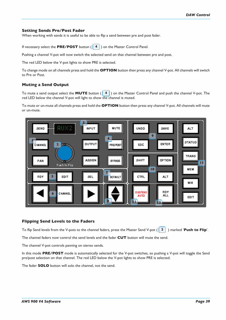
Setting Sends Pre/Post FaderWhen working with sends it is useful to be able to flip a send between pre and post fader.
If necessary select the PRE/POST button ( ) on the Master Control Panel.
Pushing a channel V-pot will now switch the selected send on that channel between pre and post.
The red LED below the V-pot lights to show PRE is selected.
To change mode on all channels press and hold theOPTION button then press any channel V-pot. All channels will switchto Pre or Post.
Muting a Send Output
To mute a send output select the MUTE button ( ) on the Master Control Panel and push the channel V-pot. Thered LED below the channel V-pot will light to show the channel is muted.
To mute or un-mute all channels press and hold theOPTION button then press any channel V-pot. All channels will muteor un-mute.
Flipping Send Levels to the Faders
To flip Send levels from the V-pots to the channel faders, press the Master Send V-pot ( ) marked ‘Push to Flip’.
The channel faders now control the send levels and the fader CUT button will mute the send.
The channel V-pot controls panning on stereo sends.
In this mode PRE/POST mode is automatically selected for the V-pot switches, so pushing a V-pot will toggle the Sendpre/post selection on that channel. The red LED below the V-pot lights to show PRE is selected.
The fader SOLO button will solo the channel, not the send.
2
12
3
4
5
6
9
7
8 11 12
13
10
4
4
DAW Control

Input, Output and Send RoutingThe channel V-pots can also be used to assign signals to inputs, outputs and aux sends of your DAW mixer:
Viewing Input, Output and Send RoutingThe Input, Output or Send routing for all DAW channels can be displayed on the channel scribble strip by holding down
the INPUT, OUTPUT or SEND button ( ) on the Master Control Panel. The Master Send V-pot can be used toselect which of the available sends you wish to display.
Setting Input, Output and Send RoutingTo make or change an Input, Output or Send assignment:
1. Select ASSIGN+ INPUT / OUTPUT or SEND on the Master Control Panel.
When using SEND, select which send you wish to change from the available send slots using the Master Send V-pot..
2. The V-pot scribble strip will now read ASGN and the fader scribble strip will indicate the current routing for theDAW channel.
3. Turn a channel V-pot to scroll through a list of available DAW inputs or outputs (names are derived from the DAWI/O settings not the AWS). The list will appear in the channel scribble strip. The red LED below the V-pot will flash.
4. Push the V-pot knob to select the current assignment; the red LED will become solid and a ‘>’ symbol will appear infront of the assigned signal (for example, ‘>Out3-4’).
5. Press theASSIGN button once more to exit assign mode. This will also commit any changes made that have not beenconfirmed by pressing the V-pot.
6. Pressing ESC at any time will abort the assignment process.
Assigning Signals to Multiple ChannelsHolding down OPTION then pressing any channel V-pot will assign that channel’s input to all channels.
Holding down SHIFT+OPTION will assign that channel’s input to all selected channels. Select SEL mode on the MasterControl Panel then press the SEL buttons on the channels you wish to route to.
Holding down OPTION and ALT then pressing a channel V-pot will incrementally route that channel’s input to allchannels. For example, selecting input 1 as the input to channel 9, then holding downOPTION and ALT before pressingthe channel 9 V-pot will route input 1 to channel 9, input 2 to channel 10, input 3 to channel 11 and so on across the entireDAW.
Holding down SHIFT+OPTION+ALT will incrementally route that channel’s input to all selected channels. Select SELmode on the Master Control Panel then press the SEL buttons on the channels you wish to route to.
Assigning a Channel to Multiple OutputsHold the CTRL button and select another output. The currently assigned output will have a ‘>’ symbol before it (forexample, ‘>Out3-4’), and other added outputs will have a ‘+’ (for example ‘+Out5-6’) until you assign it.
In the scribble strip, an ‘@’ symbol indicates that an item is inactive (ie routed but muted). The ‘$’ symbol indicates thatmore than one output is assigned, and at least one of those is inactive.
3
Page 40 AWS 900 V4 Software
DAW Control

AWS 900 V4 Software Page 41
Motion Control Panel
Transport ControlsDedicated transport controls are provided for direct control over your DAW:
ON LINE* Puts the DAW on line for synchronisation.
LOOP* Toggles Loop mode on/off (hold down CTRL for Loop Record mode).
Q PUNCH* Toggles Quickpunch recording status on/off for your DAW.
PRE* Toggles the pre-roll function for your DAW. See next page for setting Pre roll time.
POST* Toggles the post -roll function for your DAW. See next page for setting Post roll time.
*The status of these functions is shown in the transport section of the TFT screen.
IN Captures the current DAW position as the Start edit time.
OUT Captures the current DAW position as the End edit time.
RTZ (Return-To-Zero) Returns the playback cursor to the Session start time.
END Moves the playback cursor to the end of the Session.
REWIND Holding down this button will rewind the DAW (increment depends upon Display mode).
FAST FORWARD Holding down this button will fast forward the DAW.
STOP Stops playback or recording.
PLAY Depending on the HUI DAW settings commences playback from the current cursor positionor the last locate point, depending on DAW settings.
RECORD Engages DAW recording for currently armed tracks.
Other useful transport modesHalf-speed Playback SHIFT + PLAY
Abort Current Record Pass SHIFT + STOP
Cycle through Record Modes (Normal, Quickpunch, TrackPunch, Loop) CTRL + RECORD
Cycle through Machine Control Masters (accessible via the transport window) CTRL + ONLINE
Link or Unlink the Edit and Timelines SHIFT + Back slash (/)
20 22
20
27 25 26
28
21
2422
23
DAW Control

Setting Pre and Post RollHold down ALT and press the PRE or POST button to highlight the left hand numeric field of the pre-roll or post-rolltime window. The time is displayed on the console TFT screen in place of the DAW position. The selected numeric fieldwill flash. Use the navigation left/right arrow keys to select a different numeric field if required, then enter a value on thenumeric keypad or use the Up/Down arrow keys to increase or decrease the selected field.
Press ENTER to confirm the time.
The CLR button on the numeric keypad can be used to clear the selected time.
Setting start (In) and end (Out) TimesHold downALT and press the IN orOUT button to highlight the left hand numeric field of the start or end time window.The time is displayed on the AWS TFT screen in place of the DAW position. The selected numeric field will flash. Use thenavigation left/right arrow keys to select a different numeric field if required, then enter a value on the numeric keypad oruse the Up/Down arrow keys to increase or decrease the selected field.
Press ENTER to confirm the time.
The CLR button on the numeric keypad can be used to clear the selected time.
AuditionThis function allows the IN, OUT, PRE and POST points to be checked.
Select the AUD button then press either the PRE, IN, OUT, or POST button. Press the AUD button again to cancelthe function.
When Audition mode is selected the transport section of the TFT screen displays audition in place of the Pre and Postindicators.
PRE Plays from the pre-roll point to the selection start point
IN Plays from the selection start point for the post-roll time
OUT Plays from the end point less the pre-roll time to the end point
POST Plays from the selection end point for the post-roll time
ALT+OPTION+PRE or IN Plays from the selection start point less the pre-roll time to the selectionstart time plus the post-roll time
ALT+OPTION+POST or OUT Plays from the selection end point to the selection end point plus post-rolltime.
AWS Footswitch ControlThe AWS has two ¼" jack footswitch connectors on the rear of the console. These are intended for hands-free access toessential transport functions:
Footswitch Control One: Either plays or stops the DAW. Holding down SHIFT will abort a recordingif in record, or initiate half-speed playback if stopped.
Footswitch Control Two: Used to activate or deactivate Record mode. Holding CTRL while pressingthe foot switch will cycle through record modes.
20
20
20
Page 42 AWS 900 V4 Software
DAW Control

AWS 900 V4 Software Page 43
Zoom, Navigation and Selection ModesThe Motion Control panel has a section with four arrow keys and a ZOOM/SEL button that toggles the selection of threeavailable modes: Navigation Edit, Zoom and Select.
Navigation Mode (Neither Zoom nor Select lit)In this mode the arrow keys can be used to select a region or regions in certain DAWs.
The left and right arrows will snap to region/clip boundaries. The up/down arrow keys move the cursor to the track aboveor below respectively. Holding down the SHIFT modifier button will allow a selection to be extended in any direction.Holding the OPTION button allows the current selection point to be centred on the screen.
Holding CTRL+ Up/Down/Left/Right arrow button allows you to change and extend the region/clip selection. HoldingSHIFT also includes either the previous or next region.
Zoom Mode (Both Zoom and Select lit)The arrow keys now become horizontal and vertical zoom controls for the edit/arrange window on your DAW.
Fixed edit/arrange zoom settings can be saved or recalled from the AWS numeric keypad:To save a zoom setting – press SHIFT + numeric keypad numberTo recall a zoom setting – press OPTION + numeric keypad number
Select Mode (Both Zoom and Select Flashing)Currently this function is not supported in Pro Tools.
Scrolling Within a WindowTo page scroll within a currently selected window (ie. Mix/Mixer or Edit/Arrange) pressALT+ Left/Right/Up/Down arrowbutton to scroll one page in either direction. Holding down OPTION and ALT scrolls to the window boundary.
21
20
27 25 26
28
21
2422
23
DAW Control

Shuttle/Scrub WheelThe dual-concentric Shuttle/Scrub wheel has a spring-loaded outer ring and a continuously variable inner wheel forcontrolling DAW scrub and shuttle functions and for general timeline/clip navigation.
Navigation ModeWhen the inner wheel is rotated, a stream of Nudge Commands are sent to the DAW according to rotation direction andspeed. The playhead will step through the session timeline according the current nudge value. If a clip or MIDI note isselected, its position can be nudged via the wheel.
Shuttle ModeWhen the DAW is stopped, turning the outer rim activates shuttle mode. The outer rim will step through seven fixedshuttle speeds, while the inner controller provides continuously variable control of shuttle speed.
Scrub ModeSelect a region to scrub within your DAW. Press the SCRUB button next to the wheel. The inner wheel now becomesan analogue tape machine style scrub wheel for the DAW.
Using the Numeric Keypad to ShuttleIn Pro Tools, the numeric keypad can be used to control shuttle speed and direction. Engage Shuttle Mode via the outerrim. Hold down the CTRL button followed by a number on the numeric keypad that represents the shuttle speed. The+/- buttons control the direction of shuttle.
Exit from Scrub/Shuttle ModeTo exit from shuttle mode press either the STOP or ESC button. To exit from Scrub mode, deselect the SCRUB Keyor press either the STOP or ESC button.
Notes on Scrub and Shuttle Modes (PRO TOOLS HUI ONLY)The position at which the scrub/shuttle starts is derived from the current selection or timeline position. Scrub/Shuttle modecan commence from the selection end point by holding down the OPTION button before you grab the shuttle wheel.
Holding down the ALT button will increase the resolution of the scrub/shuttle wheel.
When scrub or shuttle is active, many DAW functions are suspended until you exit from scrub/shuttle mode.
The following functions are available:
• Fader control, solo and cut buttons
• Scrub/Shuttle wheel functions
• Transport controls
• Enter button (to create marker/cue events)
Numeric KeypadThe console’s numeric keypad replicates the numeric keypad on your DAW keyboard. The primary use for this keypad isfor saving and recalling Memory Locates and entering data values (please refer to your DAW manual for more details onkeypad uses).
Working with Markers/Memory LocationsTo Enter a Marker/Cue point – press ENTER.
To Recall a Marker/Cue point – press a number followed by the decimal point button (Numeric Keypad in Classic mode)or a decimal point followed by a number followed by the decimal point button (Numeric Keypad in Transport mode).
23
24
Page 44 AWS 900 V4 Software
DAW Control

AWS 900 V4 Software Page 45
HUI PLUG-IN CONTROL
Plug-In EditorAWS consoles come with a powerful Plug-in Editor located inthe console centre section. From here, plug-ins and hardwareinserts can be assigned, and plug-in parameters can be edited.
Plug-In Editor DisplayThe Plug-In Editor uses a high resolution TFT display, four V-pots and four soft buttons to control the parameters of anyplug-in.
The display is also used to show the position and status ofthe DAW and to provide access to a range of paged menus.
The currently selected EDIT channel name is displayed at thetop of the screen. Next are the plug-in control displays. Justbelow this are the transport status displays and timecodedisplay.
The bottom section is used for soft key menu selection.
Plug-In Editor ControlsThe controls for the display are located just below the screenarea. The four V-pots and associated soft keys map to thecorresponding controls on the display. The V-pots also havepush-push select switches which perform various functions.
The display also shows information from the DAW at the topof the editor display.
Paging ButtonsThe left/right paging buttons page through either available insertslots in INSERT mode, or plug-in parameters inPARAMETER mode (see following page).
Selecting DAW Channels to EditSelect EDIT mode on the Master Control Panel then use thechannel SEL buttons to choose the channel you wish to edit.The EDIT flag in the channel meter will light. The DAW willhighlight the selected channel and currently selected plug-in.Press ALT to display the plug-in window.
Alternatively, select a channel by double clicking on one of theinsert points in the Mix window. Note that from V6.4 and aboveit will be necessary to move channels 9-16, 17-24 into bay 1 channels 1-8.
Bank switching channels leaves the Plug-In Editor with the channel assigned to it. The channel EDIT tally will showthis.
1
1
2 3 4
2 3 4
DAW Control
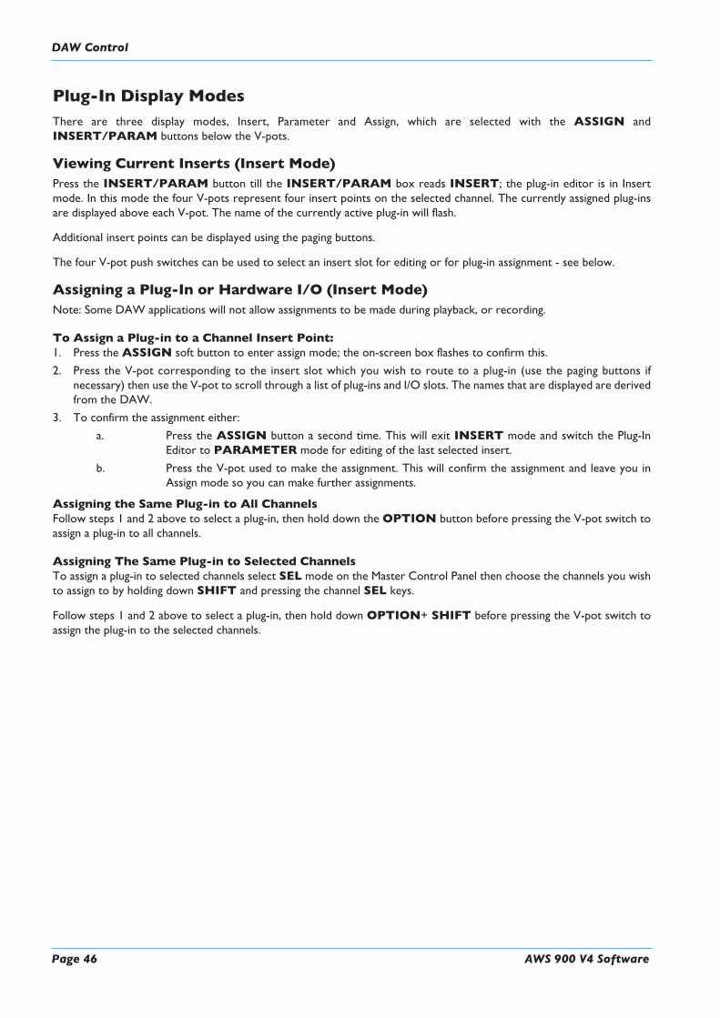
Plug-In Display ModesThere are three display modes, Insert, Parameter and Assign, which are selected with the ASSIGN andINSERT/PARAM buttons below the V-pots.
Viewing Current Inserts (Insert Mode)Press the INSERT/PARAM button till the INSERT/PARAM box reads INSERT; the plug-in editor is in Insertmode. In this mode the four V-pots represent four insert points on the selected channel. The currently assigned plug-insare displayed above each V-pot. The name of the currently active plug-in will flash.
Additional insert points can be displayed using the paging buttons.
The four V-pot push switches can be used to select an insert slot for editing or for plug-in assignment - see below.
Assigning a Plug-In or Hardware I/O (Insert Mode)Note: Some DAW applications will not allow assignments to be made during playback, or recording.
To Assign a Plug-in to a Channel Insert Point:1. Press the ASSIGN soft button to enter assign mode; the on-screen box flashes to confirm this.
2. Press the V-pot corresponding to the insert slot which you wish to route to a plug-in (use the paging buttons ifnecessary) then use the V-pot to scroll through a list of plug-ins and I/O slots. The names that are displayed are derivedfrom the DAW.
3. To confirm the assignment either:
a. Press the ASSIGN button a second time. This will exit INSERT mode and switch the Plug-InEditor to PARAMETER mode for editing of the last selected insert.
b. Press the V-pot used to make the assignment. This will confirm the assignment and leave you inAssign mode so you can make further assignments.
Assigning the Same Plug-in to All ChannelsFollow steps 1 and 2 above to select a plug-in, then hold down the OPTION button before pressing the V-pot switch toassign a plug-in to all channels.
Assigning The Same Plug-in to Selected ChannelsTo assign a plug-in to selected channels select SEL mode on the Master Control Panel then choose the channels you wishto assign to by holding down SHIFT and pressing the channel SEL keys.
Follow steps 1 and 2 above to select a plug-in, then hold down OPTION+ SHIFT before pressing the V-pot switch toassign the plug-in to the selected channels.
Page 46 AWS 900 V4 Software
DAW Control
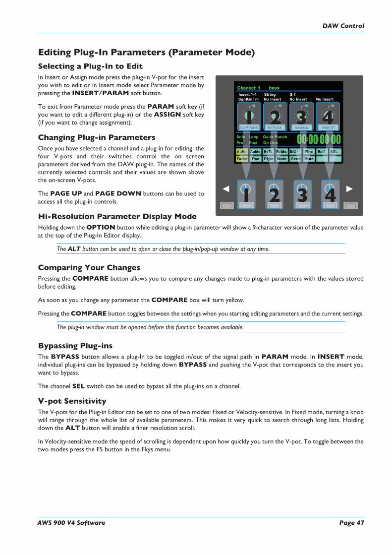
AWS 900 V4 Software Page 47
Editing Plug-In Parameters (Parameter Mode)
Selecting a Plug-In to EditIn Insert or Assign mode press the plug-in V-pot for the insertyou wish to edit or in Insert mode select Parameter mode bypressing the INSERT/PARAM soft button.
To exit from Parameter mode press the PARAM soft key (ifyou want to edit a different plug-in) or the ASSIGN soft key(if you want to change assignment).
Changing Plug-in ParametersOnce you have selected a channel and a plug-in for editing, thefour V-pots and their switches control the on screenparameters derived from the DAW plug-in. The names of thecurrently selected controls and their values are shown abovethe on-screen V-pots.
The PAGE UP and PAGE DOWN buttons can be used toaccess all the plug-in controls.
Hi-Resolution Parameter Display ModeHolding down theOPTION button while editing a plug-in parameter will show a 9-character version of the parameter valueat the top of the Plug-In Editor display.:
The ALT button can be used to open or close the plug-in/pop-up window at any time.
Comparing Your ChangesPressing the COMPARE button allows you to compare any changes made to plug-in parameters with the values storedbefore editing.
As soon as you change any parameter the COMPARE box will turn yellow.
Pressing the COMPARE button toggles between the settings when you starting editing parameters and the current settings.
The plug-in window must be opened before this function becomes available.
Bypassing Plug-insThe BYPASS button allows a plug-In to be toggled in/out of the signal path in PARAM mode. In INSERT mode,individual plug-ins can be bypassed by holding down BYPASS and pushing the V-pot that corresponds to the insert youwant to bypass.
The channel SEL switch can be used to bypass all the plug-ins on a channel.
V-pot SensitivityThe V-pots for the Plug-in Editor can be set to one of two modes: Fixed or Velocity-sensitive. In Fixed mode, turning a knobwill range through the whole list of available parameters. This makes it very quick to search through long lists. Holdingdown the ALT button will enable a finer resolution scroll.
In Velocity-sensitive mode the speed of scrolling is dependent upon how quickly you turn the V-pot. To toggle between thetwo modes press the F5 button in the Fkys menu.
1
1
2 3 4
2 3 4
DAW Control

ADDITIONAL HUI DISPLAYS
Timecode/Bars & Beats/Samples DisplayThe on-screen time readout can be assigned to display either Timecode (SMPTE/EBU), Feet/Frames, Bars/Beats or samples.This display will follow the setting selection made within your DAW. Please refer to your DAW manual for further details.
DAW Status DisplayTo the left of the timecode display is the DAW status display. This shows the following flags:
Solo DAW has a Solo active
Loop DAW has Loop enabled
QPunch DAW has QuickPunch selected
Pre DAW transport has pre-roll enabled
Post DAW transport has post-roll enabled
Solo DAW has a Solo active
Audition DAW is in Audition mode. This is displayed in place of the Pre and Post flags
Soft Key DisplayThe Plug-In Editor includes an 8x8 matrix of soft buttons which map to the 16boxes at the bottom of the plug-in display:
The top row (buttons 1-8) allow selection of the labelled function. Oncepressed, a sub-menu will appear for the second row of soft key buttons (9-16).
The menus are ordered as follows:
1. Automation Enables
Automation Enable modes (AuEn) globally engage or disengage automation for various items. See Page 4-29.
2. Automation Modes
Automation Modes (AuMo) sets the update mode for each channel or group of channels. See Page 4-29.
Soft Key Display
Page 48 AWS 900 V4 Software
DAW Control


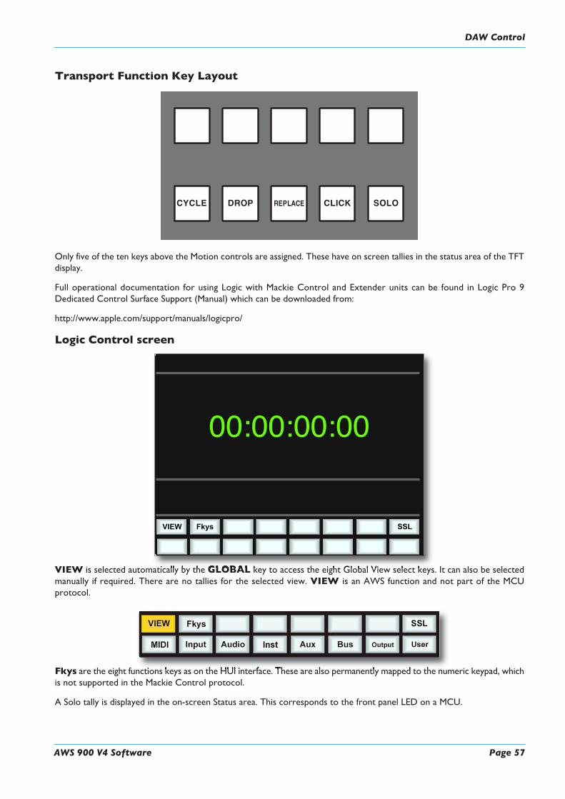

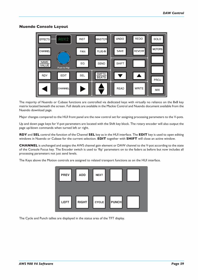

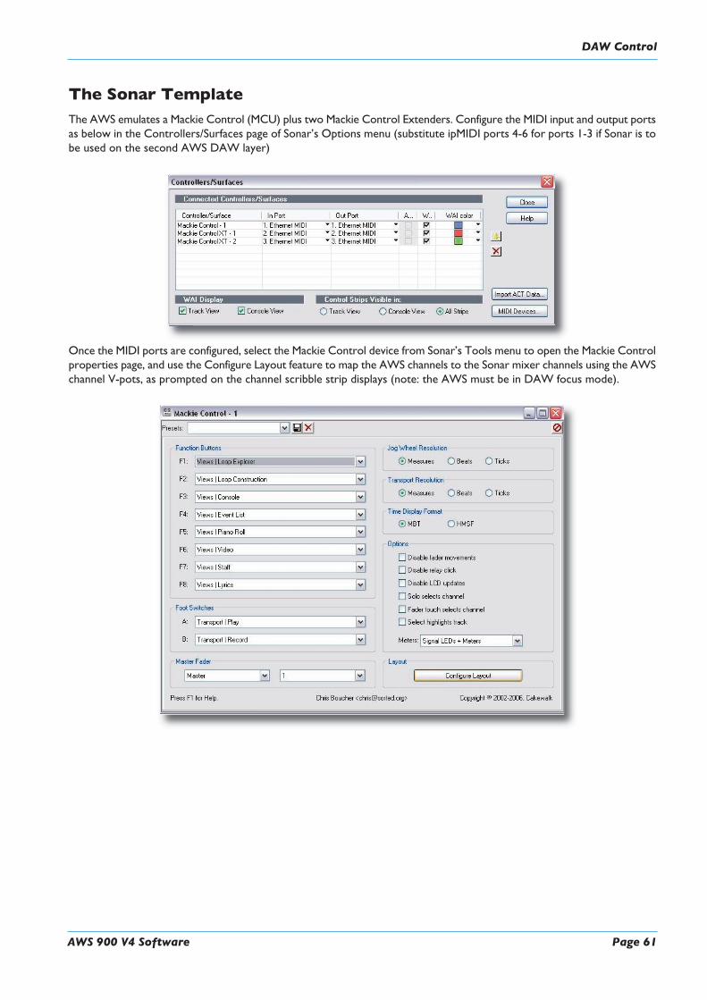


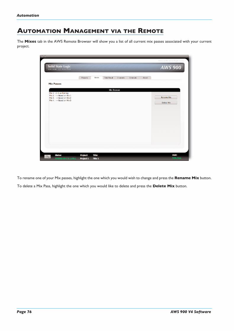
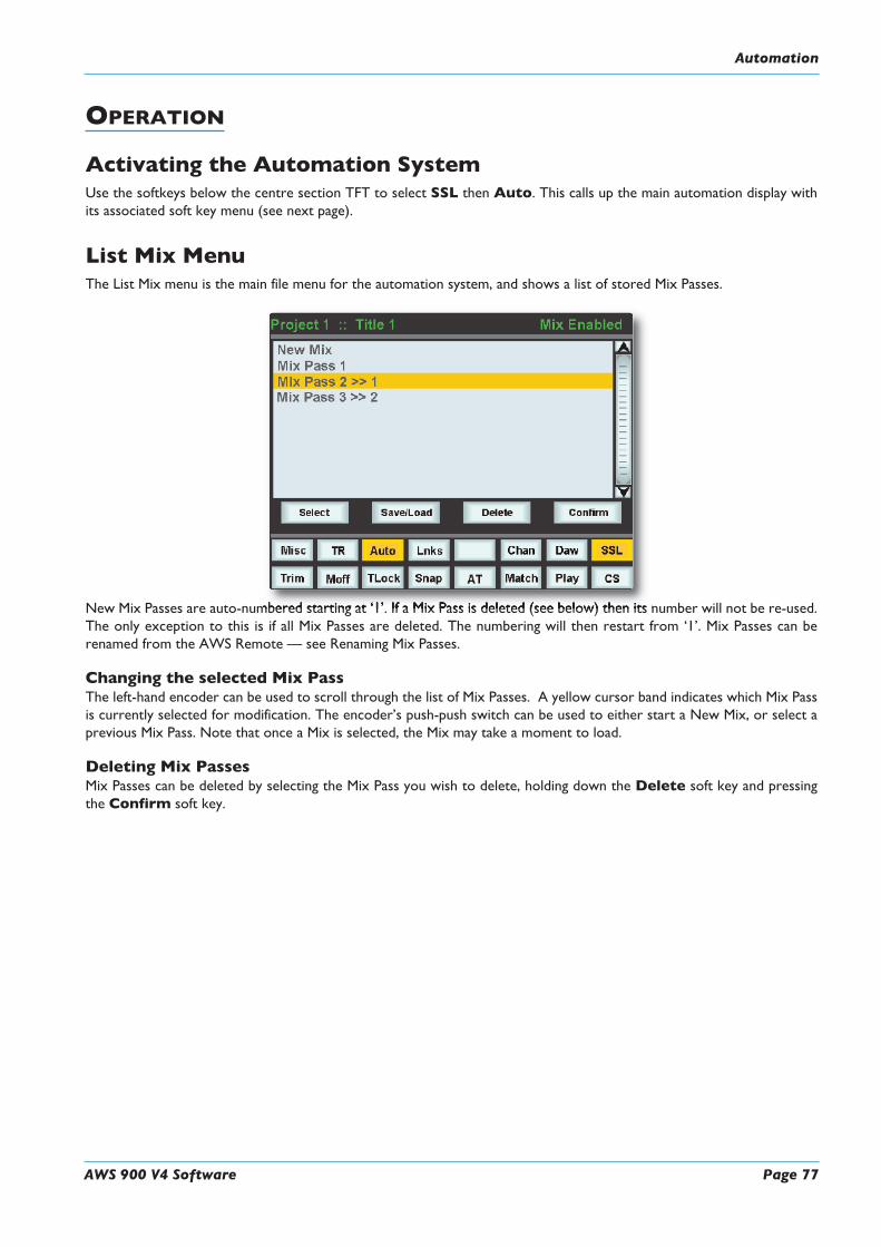


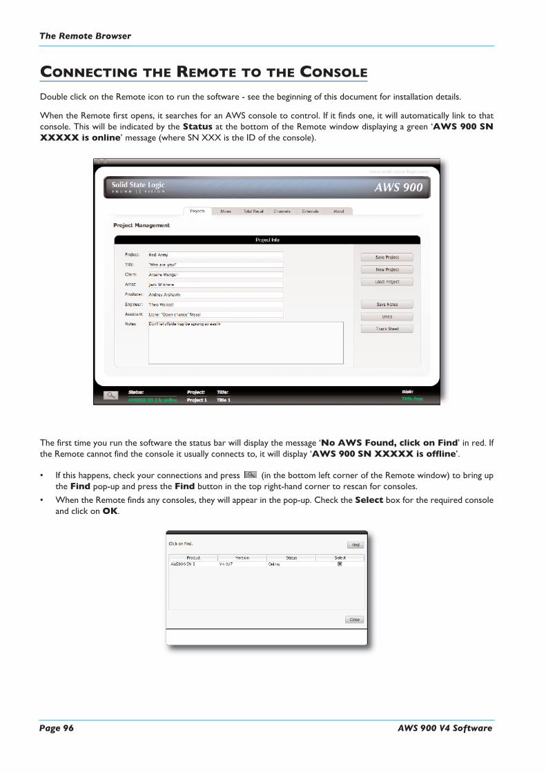


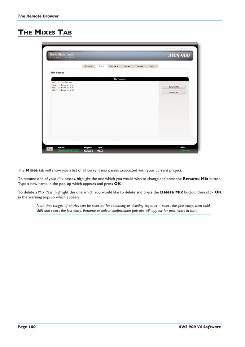


![[AWSマイスターシリーズ] AWS OpsWorks](https://img.dokumen.tips/doc/110x75/54b75fe54a7959f71f8b4650/aws-aws-opsworks.jpg)


![[AWSマイスターシリーズ] AWS CloudFormation](https://img.dokumen.tips/doc/110x75/54b73ef54a795989698b456c/aws-aws-cloudformation.jpg)