Embed Size (px)
Citation preview
AVR Programming
CS-212Dick Steflik

ATmega328P

I/O for our labs
To get data into and out of our Arduino its a little trickier than using printf and scanf as you did in CS211
Since the Arduino doesn't have an Operating System we need to write and read data directly to/from the I/O ports
Access to the ports is through the Special Function Registers (SFRs) that are defined symbolically in iom328p.h which is included in your program by io.h
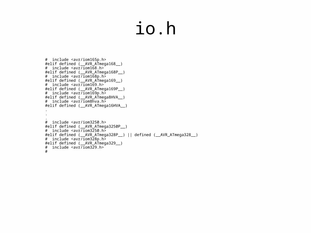
io.h
# include <avr/iom165p.h>#elif defined (__AVR_ATmega168__)# include <avr/iom168.h>#elif defined (__AVR_ATmega168P__)# include <avr/iom168p.h>#elif defined (__AVR_ATmega169__)# include <avr/iom169.h>#elif defined (__AVR_ATmega169P__)# include <avr/iom169p.h>#elif defined (__AVR_ATmega8HVA__)# include <avr/iom8hva.h>#elif defined (__AVR_ATmega16HVA__)...# include <avr/iom3250.h>#elif defined (__AVR_ATmega3250P__)# include <avr/iom3250.h>#elif defined (__AVR_ATmega328P__) || defined (__AVR_ATmega328__)# include <avr/iom328p.h>#elif defined (__AVR_ATmega329__)# include <avr/iom329.h>#
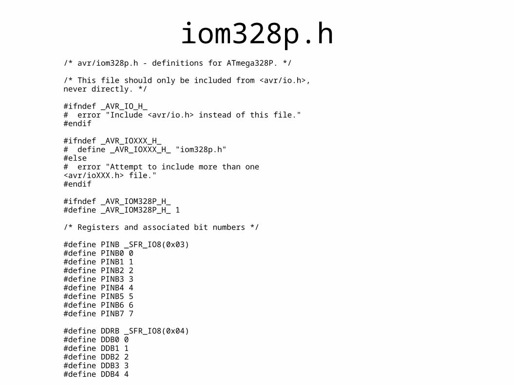
iom328p.h/* avr/iom328p.h - definitions for ATmega328P. */
/* This file should only be included from <avr/io.h>, never directly. */
#ifndef _AVR_IO_H_# error "Include <avr/io.h> instead of this file."#endif
#ifndef _AVR_IOXXX_H_# define _AVR_IOXXX_H_ "iom328p.h"#else# error "Attempt to include more than one <avr/ioXXX.h> file."#endif
#ifndef _AVR_IOM328P_H_#define _AVR_IOM328P_H_ 1
/* Registers and associated bit numbers */
#define PINB _SFR_IO8(0x03)#define PINB0 0#define PINB1 1#define PINB2 2#define PINB3 3#define PINB4 4#define PINB5 5#define PINB6 6#define PINB7 7
#define DDRB _SFR_IO8(0x04)#define DDB0 0#define DDB1 1#define DDB2 2#define DDB3 3#define DDB4 4

sfr_defs.h
included in every compile via io.h contains macro definitions for accessing
Special Function Registers as if they were just c language variables
in iom328p.h the statement: #define PINB _SFR_IO8(0x03) the symbol PINA is mapped to the SFR at address 0x03 in SFR memory
_SFR_IO8( ) is a macro (look in sfr_defs.h )

Why this is done in your program you #include io.h and io.h in
turn includes iom328p.h (because in your project definition you picked the ATmega328p as the processor)
pass 1 of the compiler does all includes and macro substitutions ( in our example with PINA all occurrences of the symbol PINB in your program will be replaced with a reference to SFR 0x03)
This makes all SFR references look like references to C variables
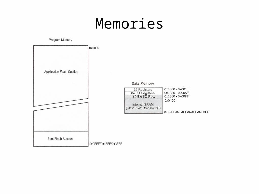
Memories
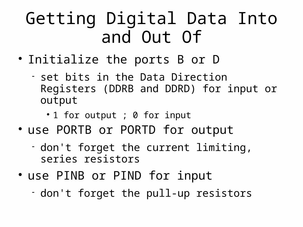
Getting Digital Data Into and Out Of
Initialize the ports B or D set bits in the Data Direction Registers (DDRB and
DDRD) for input or output 1 for output ; 0 for input
use PORTB or PORTD for output don't forget the current limiting, series resistors
use PINB or PIND for input don't forget the pull-up resistors

Blink.c/*------------------------------------------------------------------------------*//* Name: Blink.c *//* Author: Steflik */ /* Description: This is the MCU equivalent of Hello World, instead of saying */ /* “Hello World” it blinks an led at a one second rate *//*------------------------------------------------------------------------------*/
#include <avr/io.h> //This contains definitions for all the registers locations and some // other things, must always be included#define F_CPU 16000000UL //F_CPU tells the compiler that our crystal is an 16Mhz one so it // can generate an accurate delay, must be declared above delay so // delay knows what is the value of F_CPU#include <util/delay.h> //Contains some delay functions that will generate accurate delays // of ms and us
int main(void){ //In ANSI C, the main function as always an int return and using // void will give you an warning
DDRB |= (1<<PB5); //Define digital pin13/PORTB5 as an output so we can blink our led
while(1){ //This gives us an infinite loop, there should always be an infinite loop // in your code, because micro-controllers cant return from main // to anywhere and that will give you bad results and unpredicted // behavior
PORTB |= (1<<PB5); //Turn led on, this is the led included in the arduino(digital pin 13) _delay_ms(1000); //Wait 1 second PORTB &= ~(1<<PB5); //Turn led off _delay_ms(1000); //Wait another second }return 1;}

daemons
a daemon is a program that will sit in memory forever and run until the system loses power
since most embedded system run forever (until they lose power) our main() should be written as a never ending loop.
processing to be done can be done either in the body of the loop or asynchronously in response to an external or internal event (interrupt)
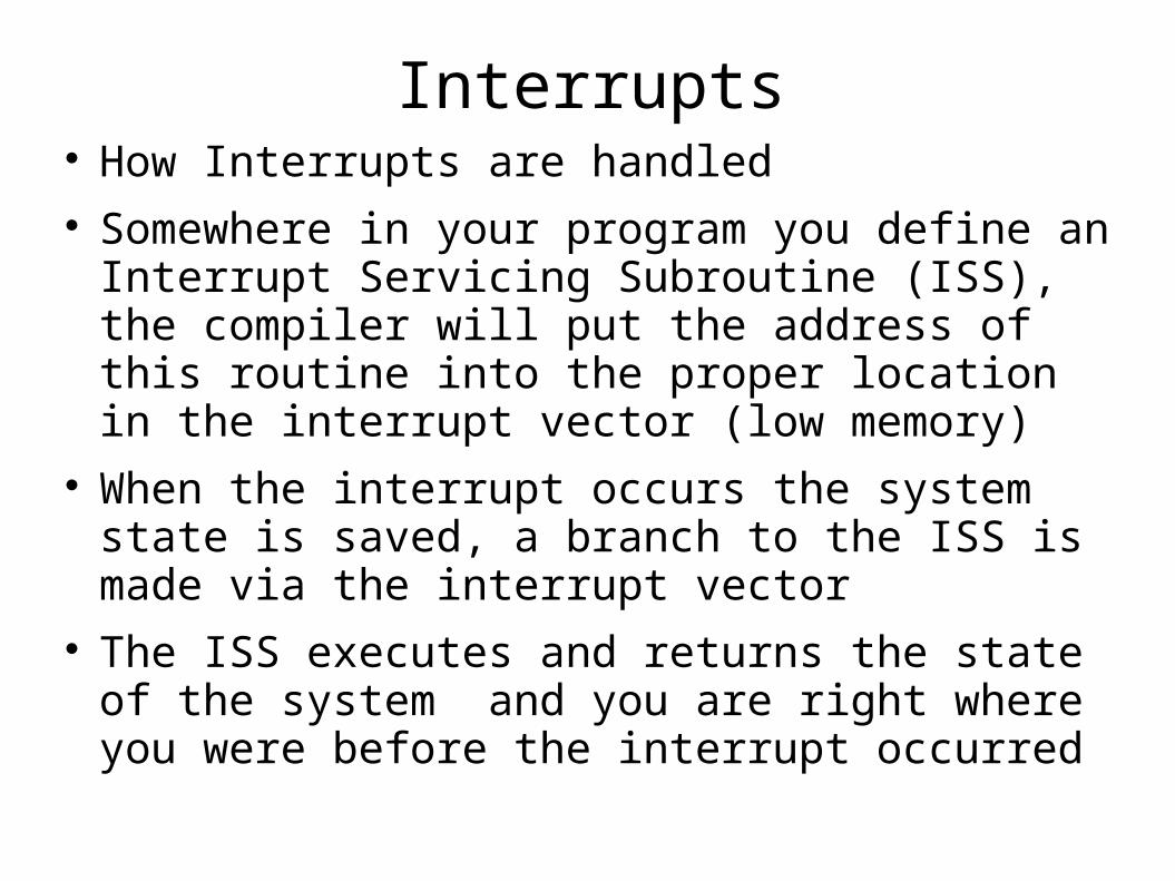
Interrupts How Interrupts are handled Somewhere in your program you define an
Interrupt Servicing Subroutine (ISS), the compiler will put the address of this routine into the proper location in the interrupt vector (low memory)
When the interrupt occurs the system state is saved, a branch to the ISS is made via the interrupt vector
The ISS executes and returns the state of the system and you are right where you were before the interrupt occurred
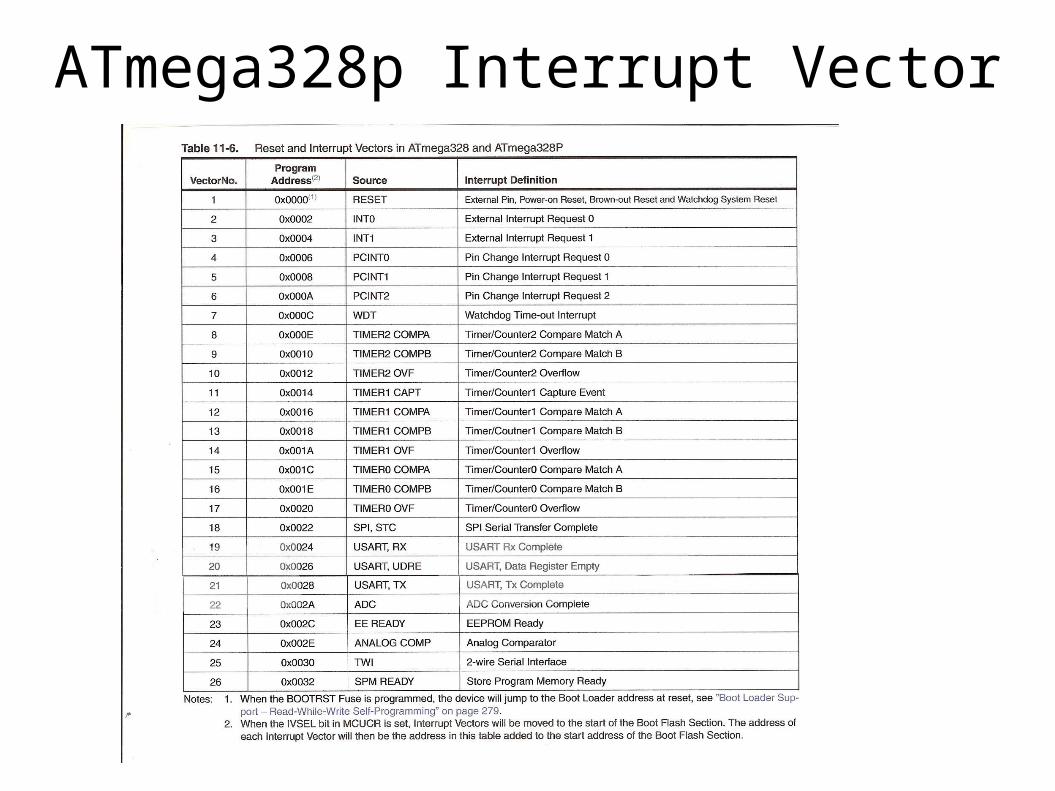
ATmega328p Interrupt Vector

What we want to do
use 8 LEDs for output 8 switches for input 1 button to tell when it is OK to read the
switches to do this we should us an interrupt

The way it should work
/* Interrupt handler */{ // disable interruptes // read the switches // save the data at the next location in an array // light the lights // enable interrupts}
int main (){ // initialize ports B & D // initial Port E for interrupt on PE2 // loop forever – this is our daemon}

volatile keyword the keyword “volatile” should be used to define
any variable that may be modified inside of an interrupt handler
“volatile” flags a variable to the optimizing compiler to not optimize variables with the “volatile” keyword
volatile char switches = 0;volatile uint8_t flags = 0;

char & uint8_t
Remember the char data type can be used for ASCII characters or a signed 8 bit integer
The AVR header files define another data type that allows an unsigned 8 bit integer, this is convenient for working with gpio ports as they are not usually signed data.

internal pullups for gpio inputs on many MCUs you must add an external
pullup resistor on gpio input lines Atmel MCUs have built-in internal pullup
resistors to use the internal pullups write a one to that line
after it has been defined as an input line in the DDR
// define Port B as all outputs and Port D as all inputsDDRB = 0xFF;DDRD = 0x00;//turn on the internal pullup resistors for Port DPORTD = 0xFF;
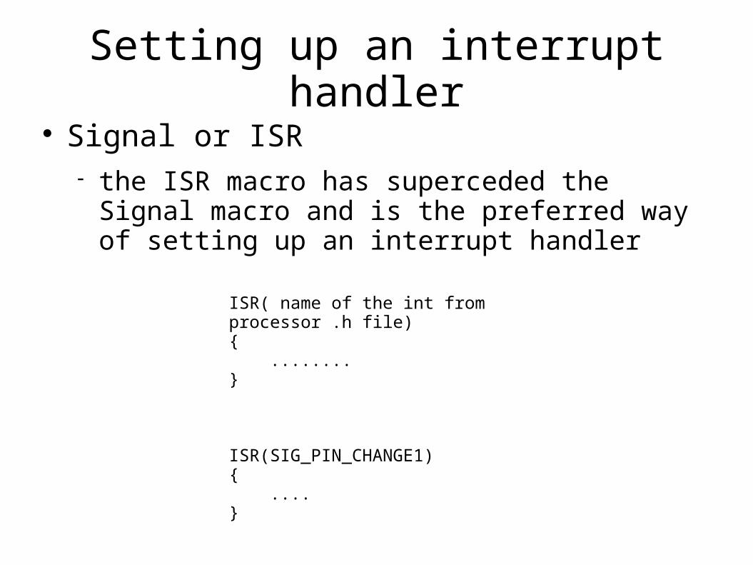
Setting up an interrupt handler Signal or ISR
the ISR macro has superceded the Signal macro and is the preferred way of setting up an interrupt handler
ISR( name of the int from processor .h file){ ........}
ISR(SIG_PIN_CHANGE1){ ....}

Pin Change Interrupts
Input lines on Ports B, C and D can be set up to generate a pin change interrupt
Each port has an associated mask register to enable an interrupt put a 1 into the correct
position in the appropriate mask register Port B PCMSK2 Port C PCMSK1 Port D PCMSK0
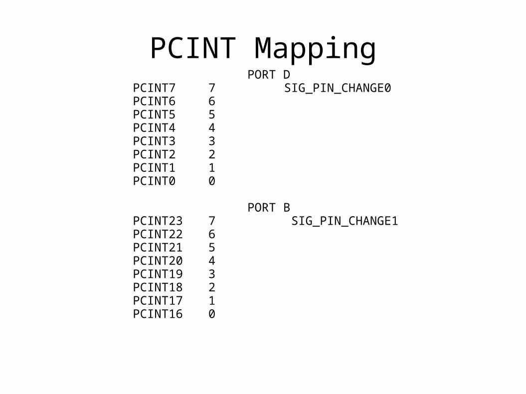
PCINT Mapping PORT DPCINT7 7 SIG_PIN_CHANGE0PCINT6 6PCINT5 5PCINT4 4PCINT3 3PCINT2 2PCINT1 1PCINT0 0
PORT BPCINT23 7 SIG_PIN_CHANGE1PCINT22 6PCINT21 5PCINT20 4PCINT19 3PCINT18 2PCINT17 1PCINT16 0

Example
//set bit 2 of Port B to cause an interruptPCMSK1 = 0x04; // set bit 2 of Port B to cause interruptEIMSK = 0xC0; // Ext Int Mask RegEIFR = 0xC0; // Ext Int Flag RegDDRB & = 0xFB; // make bit 2 an input linePORTB | = 0x04; // turn on pullup
ISR(SIG_PIN_CHANGE1){ cli( ); // disable interrupts . . . sei( ); // enable interrupts }


![ATmega328P - content.arduino.cc · 8-bit AVR Microcontroller with 32K Bytes In-System Programmable Flash DATASHEET . ATmega328P [DATASHEET] 7810D–AVR–01/15 2 I/O and packages](https://img.dokumen.tips/doc/110x75/5f1e09428682d16165458b03/atmega328p-8-bit-avr-microcontroller-with-32k-bytes-in-system-programmable-flash.jpg)


![ATmega328P - Microchip Technology · 2017. 1. 5. · ATmega328P [DATASHEET] 7810D–AVR–01/15 2 I/O and packages 23 programmable I/O lines 32-lead TQFP, and 32-pad QFN/MLF Operating](https://img.dokumen.tips/doc/110x75/609f017a931c0956070defa5/atmega328p-microchip-technology-2017-1-5-atmega328p-datasheet-7810daavra0115.jpg)