Embed Size (px)
Citation preview

Avnet Embedded. Support Around The Board™
www.avnet-embedded.eu
AvnET EmBEddEd SpEcificATion.
datasheet Navman Wireless
Jupiter 31
LA010811B © 2008 Navman Wireless OEM Solutions. All rights reserved. Proprietary information and specifications subject to change without notice.
Related documents• Jupiter 31 Product brief LA010810
• Jupiter 31 Application Note: Comparison between Jupiter 31 and Jupiter 21/J21S LA010812
• J30 Write to Flash Application Note LA000266
• Low Power Operating Modes Application Note LA000513
• SiRF NMEA reference manual
• SiRF Binary Protocol reference manual
Jupiter 31GPS receiver module
Data Sheet

LA010811B © 2008 Navman Wireless OEM Solutions. All rights reserved. Proprietary information and specifications subject to change without notice.
Contents1.0 Introduction ....................................................................................................... 52.0 Technical description ....................................................................................... 5
2.1 Product applications ..................................................................................................... 5
2.2 Architecture .................................................................................................................. 6
2.3 Physical characteristics ................................................................................................ 6
2.4 Mechanical specification .............................................................................................. 6
2.5 Environmental .............................................................................................................. 6
2.6 Compliances ................................................................................................................ 6
2.7 Marking/Serialization .................................................................................................... 7
3.0 Performance characteristics ...........................................................................73.1 TTFF (Time To First Fix) ............................................................................................... 7
3.1.1 Hot start ................................................................................................................ 73.1.2 Warm start ............................................................................................................ 73.1.3 Cold start .............................................................................................................. 7
3.2 Acquisition times .......................................................................................................... 7
3.3 Timing 1PPS output ..................................................................................................... 7
3.4 TricklePowerTM mode .................................................................................................... 73.4.1 Adaptive TricklePowerTM mode .............................................................................. 83.4.2 Push-To-FixTM mode ............................................................................................. 8
3.5 Differential aiding ......................................................................................................... 83.5.1 Differential GPS (DGPS) ...................................................................................... 83.5.2 Satellite Based Augmentation Systems (WAAS/EGNOS/MSAS) ........................ 8
3.6 Navigation modes......................................................................................................... 8
3.7 Core processor performance ....................................................................................... 8
3.8 Sensitivity ..................................................................................................................... 9
3.9 Dynamic constraints ..................................................................................................... 9
3.10 Position and velocity accuracy ................................................................................... 9
3.11 Multi-mode aiding ....................................................................................................... 9
4.0 Electrical requirements .................................................................................. 104.1 Power supply ...............................................................................................................10
4.1.1 Primary power ......................................................................................................104.1.2 Battery backup (SRAM/RTC backup) ..................................................................104.1.3 Low supply voltage detector ................................................................................104.1.4 RF (Radio Frequency) input .................................................................................104.1.5 Antenna gain ........................................................................................................104.1.6 Burnout protection ...............................................................................................104.1.7 Jamming performance .........................................................................................10
4.2 Data input and output specifications ...........................................................................11
5.0 Interfaces ......................................................................................................... 115.1 External antenna interface ..........................................................................................11
5.2 External antenna voltage ............................................................................................12
5.3 External I/O connector ................................................................................................125.3.1 I/O connector signals ...........................................................................................125.3.2 I/O connector pin dimensions .............................................................................13
6.0 Software interface .......................................................................................... 146.1 NMEA data messages .................................................................................................14

LA010811B © 2008 Navman Wireless OEM Solutions. All rights reserved. Proprietary information and specifications subject to change without notice.
6.1.1 Jupiter 31 NMEA variations .................................................................................146.2 Navman proprietary NMEA messages .......................................................................14
6.3 SiRF binary messages ................................................................................................15
6.4 Software functions and capabilities .............................................................................156.4.1 Flash (write-to-flash) upgradability ......................................................................15
7.0 Jupiter 21/31 comparison ............................................................................... 167.1 Receiver architecture ...................................................................................................16
7.2 Antenna specification ..................................................................................................16
7.3 Electrical interface .......................................................................................................16
7.4 Default baud rates .......................................................................................................16
7.5 Acquisition ...................................................................................................................17
8.0 Jupiter 31 mechanical drawing ...................................................................... 189.0 Jupiter 31 development kit ............................................................................. 1910.0 Product handling ........................................................................................... 19
10.1 Packaging and delivery ..............................................................................................19
10.2 ESD sensitivity ..........................................................................................................19
10.3 Safety ........................................................................................................................19
10.4 RoHS compliance ......................................................................................................19
10.5 Disposal .....................................................................................................................19
11.0 Ordering information .................................................................................... 1912.0 Glossary and acronyms ...............................................................................20
FiguresFigure 2-1: Jupiter 31 block diagram .................................................................................. 6
Figure 5-1: The 20-pin interface connector (J1) ................................................................13
Figure 8-1: Jupiter 31 mechanical drawing ........................................................................18

LA010811B © 2008 Navman Wireless OEM Solutions. All rights reserved. Proprietary information and specifications subject to change without notice.
TablesTable 3-1: Acquisition times ................................................................................................ 7
Table 3-2: GPS receiver sensitivity .................................................................................... 9
Table 3-3: Position and velocity accuracy .......................................................................... 9
Table 4-1: Operating power for the Jupiter 31 ...................................................................10
Table 4-2: Jamming performance .....................................................................................11
Table 4-3: Interface voltage levels ....................................................................................11
Table 5-1: External antenna voltages ................................................................................12
Table 5-2: J1 connector pin functions................................................................................12
Table 6-1: Jupiter 31 default baud rates ............................................................................14
Table 6-2: NMEA output messages ..................................................................................14
Table 6-3: Jupiter 31 NMEA message structure ...............................................................14
Table 6-4: Jupiter 31 $PTTK error messages ...................................................................15
Table 6-5: Jupiter 31 software capability ...........................................................................15
Table 7-1: Receiver architecture comparison ...................................................................16
Table 7-2: Antenna specification comparison ....................................................................16
Table 7-3: Electrical interface comparison ........................................................................16
Table 7-4: Default baud rate comparison ..........................................................................16
Table 7-5: Acquisition comparison ....................................................................................17
Table 11-1: Jupiter 31 ordering information .......................................................................19

LA010811B © 2008 Navman Wireless OEM Solutions. All rights reserved. Proprietary information and specifications subject to change without notice.
1.0 IntroductionThe Jupiter 31 is a 20 channel GPS receiver module based on the Jupiter 21 form factorthat is significantly enhanced to take advantage of the SiRFStar III architecture. TheJupiter 31 offers a substantial increase in sensitivity, faster time to fix and lower powerconsumption. The Jupiter 31 acquires GPS positions faster under low signal conditions than other available GPS engines. Tracking continues in areas of dense foliage or built-up inner cityenvironments and even indoors of sensitivity of greater than –159 dBm with the option of using either an active or passive antenna.
2.0 Technical descriptionThe Jupiter 31 is a single board GPS module solution intended for a wide range of OEM products, and provides an easy migration path from the Jupiter 21.
The highly integrated receiver incorporates and enhances the established technology of the SiRF StarIII GSC3e/LP chipset. With a high navigation sensitivity, the Jupiter 31 is designed to meet the needs of the most demanding applications and environments. The interface configuration and form factor allows incorporation into many existing devices and legacy designs.
Using the new and highly integrated GSC3e/LP from SiRF and carefully selected key components including TCXO, LNA and Flash, the Jupiter 31 offers faster acquisition, a wider operating voltage range and greater noise rejection than leading competitors’ products using a similar architecture. The Jupiter 31 receiver decodes and processes signals from all visible GPS satellites. These satellites, in various orbits around the Earth, broadcast RF (radio frequency) ranging codes, timing information, and navigation data messages. The receiver uses all available signals to produce a highly accurate navigation solution. The 20-channel architecture provides rapid TTFF (Time To First Fix) under all start-up conditions. Acquisition is guaranteed under all initialization conditions as long as available satellites are not obscured.
Satellite-based augmentation systems, such as WAAS and EGNOS, are supported to improve position accuracy.
Protocols supported are selected NMEA-0183 (National Marine Electronics Association) data messages and SiRF binary, including: latitude,longitude, elevation, velocity, heading, time, satellite tracking status, command/control messages
2.1 Product applicationsThe Jupiter 31 is designed specifically for applications where rapid TTFF and operation underlow signal levels are primary requirements. The module offers high performance and maximumflexibility in a wide range of OEM configurations such as asset tracking, fleet management and marine and vehicle navigation products. The high sensitivity of the module makes it particularly ideal for:
navigation systems – where athermic glass, or an unsuitably positioned antenna inside the vehicle will reduce visibility and signal strength
vehicle and people tracking devices – where satellites are obstructed by partially covered parking garages and walkways; Jupiter 31 will continue tracking indoors
marine buoys – where multipath and unstable sea conditions make satellite visibility irregular
asset tracking – where construction machinery is located in covered yards and areas of dense foliage
•
•
•
•

Figure 2-1: Jupiter 31 block diagram
Jupiter 31 GPS receiver module with SiRF StarIII GSC3e/LP
antenna power
3.0 V regulator
2.5 V regulator
antenna power 3.0 to 5.5 VDC
reset
BOOT
primary power 3.2 to 3.6 VDC (5 VDC option available)
backup power 2.85 to 6.0 VDC
serial port 2
1PPS
serial port 1
RF input
control/status
antenna detection
circuit
custom modules only
LA010811B © 2008 Navman Wireless OEM Solutions. All rights reserved. Proprietary information and specifications subject to change without notice.
2.2 ArchitectureA diagram of the Jupiter 31 architecture is shown in Figure 2-1.
2.3 Physical characteristicsThe Jupiter 31 is compatible with the Jupiter 21 form factor. The receiver is available in several configurations (combination of core engine and antenna connector type). The configuration must be selected at the time of ordering and is not available for field retrofitting. Refer to Table 12-1 for Jupiter 31 part ordering information.
2.4 Mechanical specificationThe physical dimensions of the Jupiter 31 are as follows:
length: 71.1 mmwidth: 40.6 mmthickness: 10.0 mmweight: 25.0 g
Refer to Figure 9-1 for the Jupiter 31 mechanical drawing.
2.5 EnvironmentalThe environmental operating conditions of the Jupiter 31 are as follows:
temperature: –40ºC to +85ºChumidity: 95% non-condensing or a wet bulb temperature of +35ºCaltitude: –300 m to 18 000 mvehicle jerk: 5 m/s3 maxvibration: random vibration IEC 68-2-64shock (non-operating): 18 G peak, 5 msacceleration (operating): 4 G (39.2 m/s2) max
2.6 CompliancesThe Jupiter 31 complies with the following:
Directive 2002/95/EC on the restriction of the use of certain hazardous substances in electrical and electronic equipment (RoHS)
CISPR22 and FCC: Part 15, Class B for radiated emissions
Automotive standard TS 16949
Manufactured in an ISO 9000 : 2000 accredited facility
•
•
•
•
LA010811B © 2008 Navman Wireless OEM Solutions. All rights reserved. Proprietary information and specifications subject to change without notice.
2.7 Marking/SerialisationThe Jupiter 31 supports a 128 barcode indicating the unit serial number. The Navman 13-character serial number convention is:
characters 1 and 2: year of manufacture (e.g. 06 = 2006, 07 = 2007)characters 3 and 4: week of manufacture (1 to 52, starting first week in January)character 5: manufacturer codecharacters 6 and 7: product and typecharacter 8: product revisioncharacters 9-13: sequential serial number
3.0 Performance characteristicsAll parameters specified in this section are based on room temperature conditions (22 ± 2°C) and a typical power supply voltage (3.3 ± 0.1 V or 5.0 ± 0.1 V) unless otherwise stated.
3.1 TTFF (Time To First Fix)TTFF is the actual time required by a GPS receiver to achieve a position solution. This specification will vary with the operating state of the receiver, the length of time since the last position fix, the location of the last fix, and the specific antenna design. Use of battery backup is recommended for proper operation.
3.1.1 Hot startA hot start results from a software reset after a period of continuous navigation, or a return from a short idle period (i.e. a few minutes) that was preceded by a period of continuous navigation. In this state, all of the critical data (position, velocity, time, and satellite ephemeris) is valid to the specified accuracy and available in SRAM. Battery backup of the SRAM and RTC during loss of power is required to achieve a hot start.
3.1.2 Warm startA warm start typically results from user-supplied position and time initialization data or continuous RTC operation with an accurate last known position available in memory. In this state, position and time data are present and valid but ephemeris data validity has expired.
3.1.3 Cold startA cold start acquisition results when either position or time data is unknown. Almanac information is used to identify previously healthy satellites.
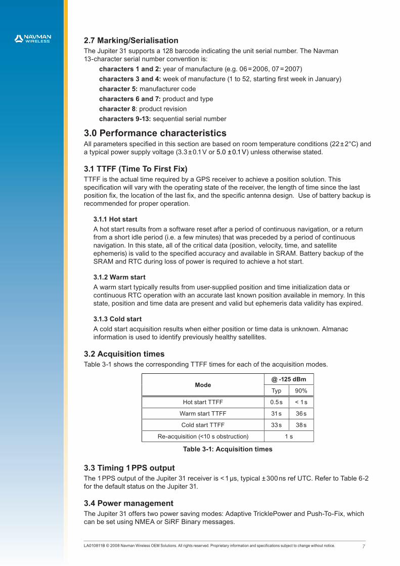
3.2 Acquisition timesTable 3-1 shows the corresponding TTFF times for each of the acquisition modes.
Mode@ -125 dBm
Typ 90%
Hot start TTFF 0.5 s < 1 s
Warm start TTFF 31 s 36 s
Cold start TTFF 33 s 38 s
Re-acquisition (<10 s obstruction) 1 s
Table 3-1: Acquisition times
3.3 Timing 1 PPS outputThe 1 PPS output of the Jupiter 31 receiver is < 1 µs, typical ± 300 ns ref UTC. Refer to Table 6-2 for the default status on the Jupiter 31.
3.4 Power managementThe Jupiter 31 offers two power saving modes: Adaptive TricklePower and Push-To-Fix, which can be set using NMEA or SiRF Binary messages.

LA010811B © 2008 Navman Wireless OEM Solutions. All rights reserved. Proprietary information and specifications subject to change without notice.
3.4.1 Adaptive TricklePowerTM modeThe Jupiter 31 can use the Adaptive TricklePower (ATP) feature, which reduces powerconsumption by intelligently switching between full power in tough GPS environments andlow power in strong GPS signal areas.
When signal levels drop, the receiver returns to full power so that message output ratesremain constant. This results in variable power savings but much more reliable performancefor a fixed output rate. Applications using ATP should give performance very similar to fullpower, but with significant power savings in strong signal conditions.
ATP is best suited for applications that require solutions at a fixed rate as well as low powerconsumption and still maintain the ability to track weak signals.
With ATP at a 1 second update, a power saving of 50% can easily be achieved with minimaldegradation in navigation performance.
3.4.2 Push-To-FixTM modeUnlike TricklePower, the operation in this mode is not cyclic. This mode always forces the GPS software to revert to a continuous sleep mode after a navigation position fix. It will stay in sleep mode until woken by activation of the reset input, and compute a fresh position.
If the ephemeris data becomes invalid, the RTC has the ability to self activate and refresh the data, thus keeping the restart TTFF very short.
This mode yields the lowest power consumption of the module, and is ideal where a battery powered application requires very few position fixes.
For further information on power management modes refer to the Low Power Operating Modes application note (LA000513).
3.5 Differential aiding3.5.1 Differential GPS (DGPS)DGPS is not available on the Jupiter 31.
3.5.2 Satellite Based Augmentation Systems, (SBAS)The Jupiter 31 is capable of receiving SBAS differential corrections including WAAS, EGNOS and MSAS. SBAS improves horizontal position accuracy by correcting GPS signal errors caused by ionospheric disturbances, timing and satellite orbit errors.
3.6 Navigation modesThe Jupiter 31 GPS receiver supports 3D (three-dimensional) and 2D (two-dimensional) modes of navigation.
3D navigation: the receiver defaults to 3D navigation when at least four GPS satellites are being tracked. In 3D navigation, the receiver computes latitude, longitude, altitude, and time information from satellite measurements.
2D navigation: when less than four GPS satellite signals are available, or when a fixed altitude value can be used to produce an acceptable navigation solution, the receiver will enter 2D navigation using a fixed value of altitude determined by the host. Forced operation in 2D mode can be commanded by the host.
In 2D navigation, the navigational accuracy is primarily determined by the relationship of the fixed altitude value to the true altitude of the antenna. If the fixed value is correct, the specified horizontal accuracies apply. Otherwise, the horizontal accuracies will degrade as a function of the error in the fixed altitude.
3.7 Core processor performanceThe standard Jupiter 31 runs at a CPU clock speed of up to 50 MHz. An SDK (Software Development Kit) is available from SiRF to customise the Jupiter 31 firmware.

LA010811B © 2008 Navman Wireless OEM Solutions. All rights reserved. Proprietary information and specifications subject to change without notice.
3.8 SensitivitySensitivity of the Jupiter 31 is measured assuming a system noise value of 3 dB. The sensitivityvalues are shown in Table 3-2:
Parameter C/No
acquisition - cold start –144 dBm 26 dBHz
acquisition - hot start –155 dBm 15 dBHz
navigation –157 dBm 13 dBHz
tracking –159 dBm 10 dBHz
Table 3-2: GPS receiver sensitivity
3.9 Dynamic constraintsThe Jupiter 31 receiver is programmed to deliberately lose track if more than one of the following operational limits are exceeded:
Velocity: 515 m/s (1,000 nautical miles per hour) maximumAltitude: 18,000 m (60,000 ft) maximum referenced to MSL
3.10 Position and velocity accuracyThe position and velocity accuracy of the Jupiter 31 are shown in Table 3-3, assuming fullaccuracy C/A code. These values are the same in normal operation and when AdaptiveTricklePower is active.
Parameter Value
horizontal CEP* 2.5 m
horizontal (2 dRMS) 5.5 m
vertical VEP* 2.0 m
velocity (speed)** < 0.01m/s
velocity (heading)** < 0.01o
* position error 0% and under normal open sky conditions** In 3D Kalman filtered mode in steady state oen sky conditions
Table 3-3: Position and velocity accuracy
3.11 Multi-mode aiding
Multi-mode aiding technology makes navigation information available to GPS devices when enough Satellite Vehicles (SVs) are not visible due to obstruction. In autonomous operation mode, the GPS receiver requires a signal level of 28 dBHz or higher in four or more SVs to download ephemerides. This requires an uninterrupted full 30 seconds of data reception from each SV. If the data isn’t received in full, the ephemeris data collection has to start again at the next cycle.
The type of multi-mode aiding currently supported by the Jupiter 32 xLP is Ephemeris Push. This feature supports live ephemeris data to be downloaded from application servers that allows hot start performance at all times including in weak conditions and moving start ups. The ephemeris would typically be valid for 4 hours until the live ephemeris is downloaded or new ephemeris data is provided.
To use with this Ephemeris Push, the live ephemeris data is collected at application servers and then transmitted to the GPS receiver through a network connection. An application note about Ephemeris Push is in preparation and will be available at a later date.
10LA010811B © 2008 Navman Wireless OEM Solutions. All rights reserved. Proprietary information and specifications subject to change without notice.
4.0 Electrical requirementsAll parameters specified in this section are based on room temperature conditions (22 ± 2°C) and a typical power supply voltage (3.3 ± 0.1 V or 5.0 ± 0.1 V ) unless otherwise stated.
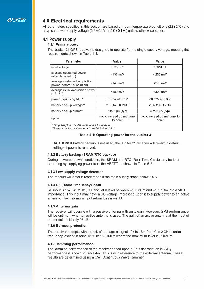
4.1 Power supply4.1.1 Primary powerThe Jupiter 31 GPS receiver is designed to operate from a single supply voltage, meeting the requirements shown in Table 4-1.
Parameter Value Value
input voltage 3.3 VDC 5.0 VDC
average sustained power(after 1st solution) <136 mW <250 mW
average sustained acquisition power (before 1st solution) <149 mW <275 mW
average initial acquisition power (1.5–2 s) <189 mW <300 mW
power (typ) using ATP* 80 mW at 3.3 V 80 mW at 3.3 V
battery backup voltage** 2.85 to 6.0 VDC 2.85 to 6.0 VDC
battery backup current 5 to 6 µA (typ) 5 to 6 µA (typ)
ripple not to exceed 50 mV peak to peak
not to exceed 50 mV peak to peak
*Using Adaptive TricklePower with a 1 s update**Battery backup voltage must not fall below 2.5 V
Table 4-1: Operating power for the Jupiter 31
CAUTION! If battery backup is not used, the Jupiter 31 receiver will revert to default settings if power is removed.
4.1.2 Battery backup (SRAM/RTC backup)During ‘powered down’ conditions, the SRAM and RTC (Real Time Clock) may be kept operating by supplying power from the VBATT as shown in Table 5-2.
4.1.3 Low supply voltage detectorThe module will enter a reset mode if the main supply drops below 3.0 V.
4.1.4 RF (Radio Frequency) inputRF input is 1575.42 MHz (L1 Band) at a level between –135 dBm and –159 dBm into a 50 Ω impedance. This input may have a DC voltage impressed upon it to supply power to an active antenna. The maximum input return loss is –9 dB.
4.1.5 Antenna gainThe receiver will operate with a passive antenna with unity gain. However, GPS performance will be optimum when an active antenna is used. The gain of an active antenna at the input of the module is ideally 16 dB.
4.1.6 Burnout protection
The receiver accepts without risk of damage a signal of +10 dBm from 0 to 2 GHz carrier frequency, except in band 1560 to 1590 MHz where the maximum level is –10 dBm.
4.1.7 Jamming performanceThe jamming performance of the receiver based upon a 3 dB degradation in C/N0 performance is shown in Table 4-2. This is with reference to the external antenna. These results are determined using a CW (Continuous Wave) Jammer.

11LA010811B © 2008 Navman Wireless OEM Solutions. All rights reserved. Proprietary information and specifications subject to change without notice.
Frequency MHz Jamming signal power dBm
200 3
400 4
800 –9
1400 –2
1425.42 –2
1530 –11
1555 –44
1575.42 –97
1625.42 –4
1725.42 –2
Table 4-2: Jamming performance
4.2 Data input output specificationsThe I/O connector voltage levels measured at PWR-IN=3.3V and 5.0V are shown in Table 4-3.
Signal Parameter Value at 3.3VDC Value at 5.0VDC
TXD & RXD GPIOs
VIH (min) 2.0 V 2.0V
VIH (max) 5.5 V 5.5V
VIL (min) -0.5 V -0.5V
VIL (max) 0.8 V 0.8V
VOH (min) at IOH -50uA 3.2V 4.9V
VOH (min) at IOH -4mA 2.88 V 4.58V
VOH (max) 3.3 V 5.0V
VOL (min) at IOL 50uA 0 V 0V
VOL (max) at IOL 4mA 0.36 V 0.36V
Reset input*
max capacitance Cmax 100 pF 100pF
Max rise and fall time 250 ms 250 ms
Input current max -600 uA -600 uA
*Reset input should not be driven high external circuits. It is recommended this input is driven low by an open drain interface.
Table 4-3: Interface voltage levels
5.0 Interfaces5.1 External antenna interfaceThe Jupiter 31 is available with the following antenna connector configurations:
• OSX jack, straight (female)
• OSX jack, right angle (female)
• SMB jack, right angle (female)
Note that SMB connectors do not follow the same ‘gender’ convention as other RF connectors. The SMB right angle connectors are classed female even though it has a pin and would be classed male in other variations of connectors.
12LA010811B © 2008 Navman Wireless OEM Solutions. All rights reserved. Proprietary information and specifications subject to change without notice.
5.2 External antenna voltageThe Jupiter 31 provides DC power to the external active antenna through the antenna power input pad (VANT). The DC supply in the coax cable is vulnerable to over current if a fault occurs in the antenna or if the antenna cable gets damaged.
Typical values for the external antenna are shown in Table 5-1.
Parameter J31
voltage (typ) 3 VDC
voltage max 12 VDC
antenna current limit 50 mA
Table 5-1: External antenna voltages
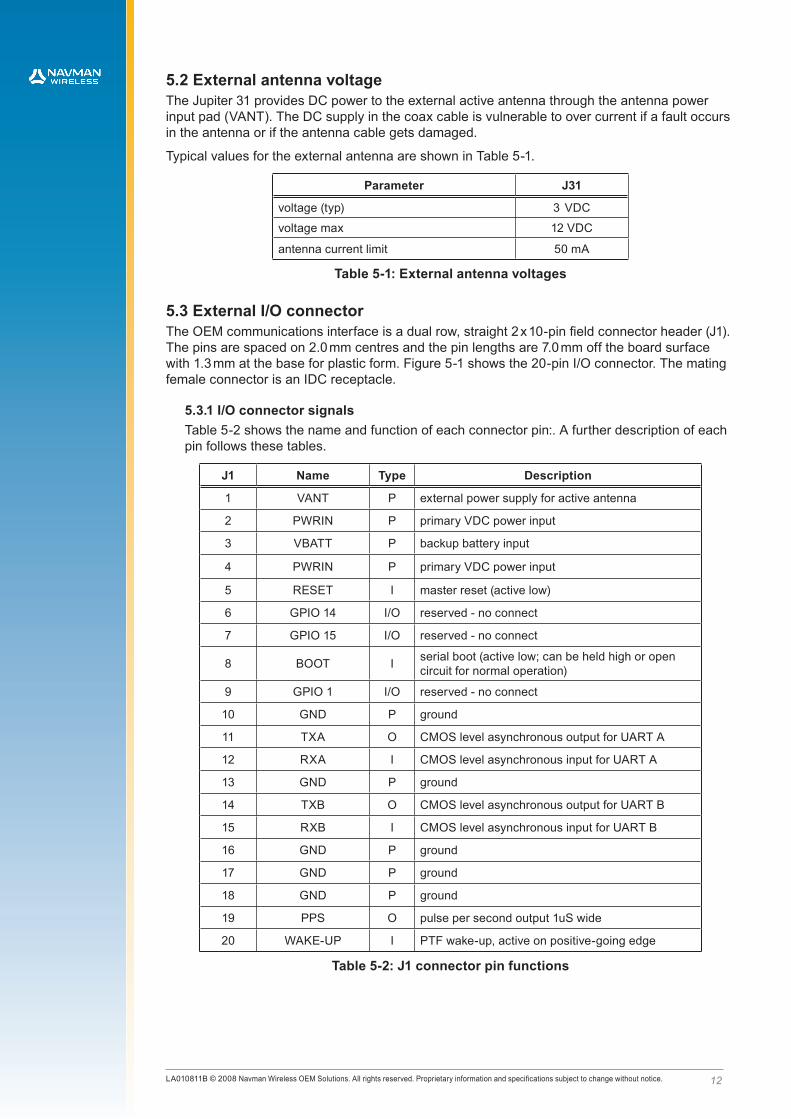
5.3 External I/O connectorThe OEM communications interface is a dual row, straight 2 x 10-pin field connector header (J1). The pins are spaced on 2.0 mm centres and the pin lengths are 7.0 mm off the board surface with 1.3 mm at the base for plastic form. Figure 5-1 shows the 20-pin I/O connector. The mating female connector is an IDC receptacle.
5.3.1 I/O connector signalsTable 5-2 shows the name and function of each connector pin:. A further description of each pin follows these tables.
J1 Name Type Description
1 VANT P external power supply for active antenna
2 PWRIN P primary VDC power input
3 VBATT P backup battery input
4 PWRIN P primary VDC power input
5 RESET I master reset (active low)
6 GPIO 14 I/O reserved - no connect
7 GPIO 15 I/O reserved - no connect
8 BOOT I serial boot (active low; can be held high or open circuit for normal operation)
9 GPIO 1 I/O reserved - no connect
10 GND P ground
11 TXA O CMOS level asynchronous output for UART A
12 RXA I CMOS level asynchronous input for UART A
13 GND P ground
14 TXB O CMOS level asynchronous output for UART B
15 RXB I CMOS level asynchronous input for UART B
16 GND P ground
17 GND P ground
18 GND P ground
19 PPS O pulse per second output 1uS wide
20 WAKE-UP I PTF wake-up, active on positive-going edge
Table 5-2: J1 connector pin functions

13LA010811B © 2008 Navman Wireless OEM Solutions. All rights reserved. Proprietary information and specifications subject to change without notice.
Pin 1: VANTThis pin supplies DC power to the external antenna. Refer to Section 5.2 for more details.
Pin 2 & 4: PWRINJupiter 31 supports either 3.2 VDC to 3.6 VDC or 4.75VDC to 5.25VDC. The main power must be regulated and have maximum ripple of 50 mV. Contact your distributor or Navman Wireless for more information.
Pin 3: VBATTThe VBATT (battery backup) pin can supply power to the SRAM and RTC (Real Time Clock) during ‘powered down’ conditions (refer to Table 4-1). The Jupiter 31 can accept slow VBATT supply rise time due to an on-board voltage detector.
Pin 5: RESETThis active low input allows the user to restart the software from an external signal. In normal operation this pin should be left floating or activated by an open drain driver. Active pull-up is not recommended.
Pin 8: BOOTThe firmware programmed in the Flash memory may be upgraded via the serial port. The user can control this by pulling the Serial BOOT pin (8) low at startup, then downloading the code from a PC with suitable software (e.g. SiRFFlash). In normal operation this pin should be left floating for minimal current drain. It is recommended that in a user application, the BOOT pin is connected to a test pad for use in future software upgrades.
Pins 11, 12, 14 and 15: serial data portsSerial port A (pins 11 and 12), also called the host port, is the primary communications port of the receiver. Commands to the receiver are entered through pin 12 (RXA) and data from the receiver is transmitted through pin 11 (TXA). Binary or NMEA messages are transmitted and received across the host port’s serial I/O interface.
Serial port B (pins 14 and 15) is, also called the auxiliary port. By default serial port B is at 38400 baud and Null on protocol.
Pin 19: 1PPS time mark pulseThe Jupiter 31 receiver generates a 1PPS positive-going output pulse of 1 µs, typical ± 300 ns which is aligned to Universal Time Coordinated (UTC) second.
Pin 20: Wake-up Wake-up pin input only to be activated in Push-To-Fix mode once the device has been commanded into this mode and the device is in Hibernate mode. This input is activated by a positive going pulse.
5.3.2 I/O connector pin dimensions
component body
0.50 square
20.0
18.0
2.0
2.0
7.05.5
4.0
all measurements are in mm
1
2 4 6 8 10 12 14 16 18 20
19171513117 953
Figure 5-1: The 20-pin interface connector (J1)

14LA010811B © 2008 Navman Wireless OEM Solutions. All rights reserved. Proprietary information and specifications subject to change without notice.
6.0 Software interfaceThe host serial I/O port of the receiver’s serial data interface supports full duplex communication between the receiver and the user. The default serial modes are shown in Table 6-1.
Port J31
Port A NMEA, 4800
Port B NULL, 38 400
Table 6-1: Jupiter 31 default baud rates
6.1 NMEA data messagesThe output NMEA (0183 v2.2) messages and refresh rates of the Jupiter 31 receiver are listed in Table 6-2. A complete description of each NMEA message is contained in the SiRF NMEA reference manual.
Message description Message ID Value
GPS fix data GGA 1 s
GPS DOP and active satellites GSA 1 s
GPS satellites in view GSV 1 s
recommended minimum specific GPS data RMC 1 s
track made good and ground speed VTG 1 s
latitude, longitude, UTC of position fix and status GLL 1 s
PPS timing message ZDA 1 s
Table 6-2: NMEA output messages
Message name J31 NMEA structure J21 NMEA structure
GGA $GPGGA,161229.487,3723.2475,N,12158.3416,W,1,07,1.0,9.0,M,1.0,M,,0000*18
$GPGGA,161229,3723.2475,N,12158.3416,W,1,07,1.00,9.0,M,1.0,M, , *18
GSA $GPGSA,A,3,07,02,26,27,09,04,15, , , , , ,1.8,1.0,1.5*33
$GPGSA,A,3,07,02,26,27,09,04,15, , , , , ,1.80,1.00,1.50*33
RMC $GPRMC,161229.487,A,3723.2475,N,12158.3416,W,0.13,309.62,120598,,*10
$GPRMC,161229,A,3723.2475,N,12158.3416,W,0.130,309.6,120598,23.1,E*10
VTG $GPVTG,309.62,T,,M,0.13,N,0.2,K*23$GPVTG,309.6,T,286.5,M,0.130,N,0.200,K,A*23
ZDA $GPZDA,181813.000,14,10,2003,,*4F $GPZDA,181813.00,14,10,2003,00,00*4F
Table 6-3: Jupiter 31 NMEA message structure
For detailed software comparison between J31 and J21 please refer to Comparison between Jupiter 31 and Jupiter 21/J21S (LA010812).
6.2 Navman proprietary NMEA messagesNavman has added a number of proprietary NMEA input messages to configure the TricklePower and Push-To-Fix modes.
These are described in the J30 Write to Flash Application Note LA000266 and the Low Power Operating Modes Application Note LA000513.
1LA010811B © 2008 Navman Wireless OEM Solutions. All rights reserved. Proprietary information and specifications subject to change without notice.
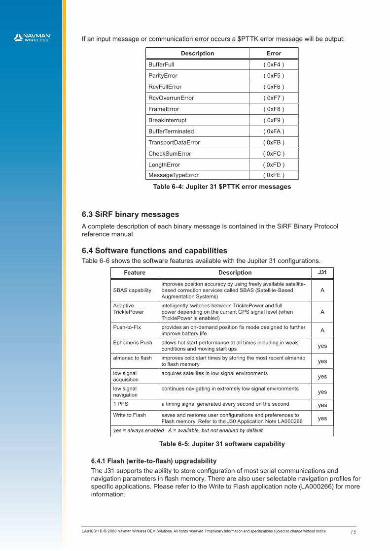
If an input message or communication error occurs a $PTTK error message will be output:
Description Error
BufferFull ( 0xF4 )
ParityError ( 0xF5 )
RcvFullError ( 0xF6 )
RcvOverrunError ( 0xF7 )
FrameError ( 0xF8 )
BreakInterrupt ( 0xF9 )
BufferTerminated ( 0xFA )
TransportDataError ( 0xFB )
CheckSumError ( 0xFC )
LengthError ( 0xFD )
MessageTypeError ( 0xFE )
Table 6-4: Jupiter 31 $PTTK error messages
6.3 SiRF binary messagesA complete description of each binary message is contained in the SiRF Binary Protocol reference manual.
6.4 Software functions and capabilitiesTable 6-6 shows the software features available with the Jupiter 31 configurations.
Feature Description J31
SBAS capabilityimproves position accuracy by using freely available satellite-based correction services called SBAS (Satellite-Based Augmentation Systems)
A
Adaptive TricklePower
intelligently switches between TricklePower and full power depending on the current GPS signal level (when TricklePower is enabled)
A
Push-to-Fix provides an on-demand position fix mode designed to further improve battery life A
Ephemeris Push allows hot start performance at all times including in weak conditions and moving start ups yes
almanac to flash improves cold start times by storing the most recent almanac to flash memory yes
low signal acquisition
acquires satellites in low signal environments yes
low signal navigation
continues navigating in extremely low signal environments yes
1 PPS a timing signal generated every second on the second yes
Write to Flash saves and restores user configurations and preferences to Flash memory. Refer to the J30 Application Note LA000266 yes
yes = always enabled A = available, but not enabled by default
Table 6-5: Jupiter 31 software capability
6.4.1 Flash (write-to-flash) upgradabilityThe J31 supports the ability to store configuration of most serial communications and navigation parameters in flash memory. There are also user selectable navigation profiles for specific applications. Please refer to the Write to Flash application note (LA000266) for more information.

1LA010811B © 2008 Navman Wireless OEM Solutions. All rights reserved. Proprietary information and specifications subject to change without notice.
7.0 Jupiter 21/31 comparisonThis section highlights the differences between the Jupiter 21 and Jupiter 31 to assist with upgrade in legacy applications. For more detailed information refer to the Jupiter 31 Application Note: Comparison between Jupiter 31 and Jupiter 21/J21S (LA010812).
7.1 Receiver architectureFeature Jupiter 21 Jupiter 31 Performance differences
receiver design SiRFStarIIe/LP chipset
SiRFStarIIIGSC3e/LP chipset
1) J31 has faster TTFF2) J31 has lower power
consumption3) J31 has greater receiver
sensitivity
Table 7-1: Receiver architecture comparison
7.2 Antenna specificationFeature Jupiter 21 Jupiter 31
antenna gainactive antenna gain should be in the range of 20 to 30 dB
best results achieved with an active antenna gain of 16 dB at the module input
Table 7-2: Antenna specification comparison
7.3 Electrical interfaceThe following table highlights the differences between the electrical connector pin configurations.
pin Jupiter 21 name Jupiter 31 name Differences
15 RXB RXB
J21: second serial data input port. J21/J21D only receives DGPS messages in RTCM (J21S does not support DGPS).
J31: does not support DGPS messages. Defaults to Null port.
20 GPSFIX (active low) WAKEUP
J21: outputs low when the receiver has a fix, high otherwise
J31: Push-to-fix wakeup on positive going edge.
Table 7-3: Electrical interface comparison
7.4 Default baud ratesPort J21 J31
Port A NMEA, 4800 NMEA, 4800
Port B DGPS, 9600 NULL, 38 400*
*Jupiter 31 does not support DGPS
While these are the default baud rates, they can be changed using the “write-to-flash” feature. Refer to the Application note for WTF.
Table 7-4: Default baud rate comparison

1LA010811B © 2008 Navman Wireless OEM Solutions. All rights reserved. Proprietary information and specifications subject to change without notice.
7.5 Acquisition
ModeJ21 @-125
dBmJ31 @-125
dBm
Typ 90% Typ 90%
TTFF hot (valid almanac, position, time & ephemeris) 8 s 12 s 0.5 s <1 s
TTFF warm (valid almanac, position & time) 38 s 42 s 31 s 36 s
TTFF cold (valid almanac) 44 s 55 s 33 s 38 s
re-acquisition (<10 s obstruction with valid almanac,
position, time & ephemeris)1 s 1 s 1 s 1 s
Table 7-5: Acquisition comparison

top view bottom view
connector optionspositional tolerance ± 0.25
all dimensions are in mm
5.1
5.1
hole size ø 3.18 (x 4)
40.6 ± 0.7
34.3
3.18
18 pin centres
8.1
71.1
± 0
.7
3.18
3.18
angular alignment of 20-way connector within ± 0.5˚
64.7
7
side view
max. width 10.0
MCX connector, right angle(shown on main drawing)
MCX connector, straight SMB bulkhead mount
6.4
8.77.80
3.8
2.1
8.7 6.1 8.7
1.2
12.3
7.0
Figure 8-1: Jupiter 31 mechanical drawing
1LA010811B © 2008 Navman Wireless OEM Solutions. All rights reserved. Proprietary information and specifications subject to change without notice.
8.0 Jupiter 31 mechanical drawing
1LA010811B © 2008 Navman Wireless OEM Solutions. All rights reserved. Proprietary information and specifications subject to change without notice.
9.0 Jupiter 31 development kit
Since the Jupiter 31 module is similar to earlier Jupiter modules, a development kit is notcurrently planned for this product. A legacy development kit contains all the necessary hardwareto carry out a thorough evaluation of the Jupiter 31 module. Additional information is provided in the Jupiter 31 Application Note: Comparison between Jupiter 31 and Jupiter 21/J21S (LA010812) from Navman Wireless.
10.0 Product handling10.1 Packaging and deliveryThe Jupiter 31 modules are packed in quantities of 10 in an anti-static tray with fitted lid. The lid is labelled with an ESD Caution. Five such trays are shipped in a box.
10.2 ESD sensitivityThe Jupiter 31 GPS receiver contains class 1 devices and is ESDS (ElectroStatic Discharge Sensitive). Navman recommends the two basic principles of protecting ESDS devices from damage:
• Only handle sensitive components in an ESD Protected Area (EPA) under protected and controlled conditions
• Protect sensitive devices outside the EPA using ESD protective packaging
All personnel handling ESDS devices have the responsibility to be aware of the ESD threat to reliability of electronic products.
Further information can be obtained from the IEC Technical Report IEC61340-5-1 & 2: Protection of electronic devices from electrostatic phenomena.
10.3 SafetyImproper handling and use of the Jupiter GPS receiver can cause permanent damage to the receiver and may even result in personal injury.
10.4 RoHS complianceThis product complies with Directive 2002/95/EC on the restriction of the use of certain hazardous substances in electrical and electronic equipment.
10.5 DisposalWe recommend that this product should not be treated as household waste. For more detailed information about recycling of this product, please contact your local waste management authority or the reseller from whom you purchased the product.

20LA010811B © 2008 Navman Wireless OEM Solutions. All rights reserved. Proprietary information and specifications subject to change without notice.
11.0 Ordering informationThe part numbers of the Jupiter 31 variants are shown in Table 11-1.
Part Number Description
AA003041-G Jupiter 31 with right angle OSX 3.3Volt
AA003042-G Jupiter 31 with straight OSX 3.3Volt
AA003043-G Jupiter 31 with right angle SMB 3.3Volt
AA003045-G Jupiter 31 with right angle OSX 5Volt
AA003046-G Jupiter 31 with straight OSX 5Volt
AA003047-G Jupiter 31 with right angle SMB 5Volt
Table 11-1: Jupiter 31 ordering information

21LA010811B © 2008 Navman Wireless OEM Solutions. All rights reserved. Proprietary information and specifications subject to change without notice.
12.0 Glossary and acronyms
2dRMS: twice distance Root Mean Square
Almanac: A set of orbital parameters that allows calculation of approximate GPS satellite positions and velocities. The almanac is used by a GPS receiver to determine satellite visibility and as an aid during acquisition of GPS satellite signals. The almanac is a subset of satellite ephemeris data and is updated weekly by GPS Control.
C/A code: Coarse Acquisition code A spread spectrum direct sequence code that is used primarily by commercial GPS receivers to determine the range to the transmitting GPS satellite.
C/No: Carrier to Noise ratio A measure of the received carrier strength relative to the strength of the received noise (measured in dB).
DGPS: Differential GPS A technique to improve GPS accuracy that uses pseudo-range errors recorded at a known location to improve the measurements made by other GPS receivers within the same general geographic area.
GDOP: Geometric Dilution of Precision A factor used to describe the effect of the satellite geometry on the position and time accuracy of the GPS receiver solution. The lower the value of the GDOP parameter, the less the error in the position solution. Related indicators include PDOP, HDOP, TDOP and VDOP.
EGNOS: European Geostationary Navigation Overlay Service The system of geostationary satellites and ground stations developed in Europe to improve the position and time calculation performed by the GPS receiver.
Ephemeris: A set of satellite orbital parameters that is used by a GPS receiver to calculate precise GPS satellite positions and velocities. The ephemeris is used to determine the navigation solution and is updated frequently to maintain the accuracy of GPS receivers.
GPS: Global Positioning System A space-based radio positioning system that provides accurate position, velocity, and time data.
OEM: Original Equipment Manufacturer
Re-acquisition: The time taken for a position to be obtained after all satellites have been made invisible to the receiver.
SBAS: Satellite Based Augmentation System Any system that uses a network of geostationary satellites and ground stations to improve the performance of a Global Navigation Satellite System (GNSS). Current examples are EGNOS and WAAS.
SRAM: Static Random Access Memory
TTFF: Time To First FixThe actual time required by a GPS receiver to achieve a position solution. This specification will vary with the operating state of the receiver, the length of time since the last position fix, the location of the last position fix, and the specific receiver design.
UTC: Universal Time Co-ordinated The international time standard, a successor to GMT (Greenwich Mean Time).
WAAS: Wide Area Augmentation System The system of satellites and ground stations developed by the FAA (Federal Aviation Administration) that provides GPS signal corrections. WAAS satellite coverage is currently only available in North America.

22LA010811B © 2008 Navman Wireless OEM Solutions. All rights reserved. Proprietary information and specifications subject to change without notice.
© 2008 Navman Wireless OEM Solutions. All Rights Reserved.Information in this document is provided in connection with Navman Wireless (‘Navman’) products. These materials are provided by Navman as a service to its customers and may be used for informational purposes only. Navman assumes no responsibility for errors or omissions in these materials. Navman may make changes to specifications and product descriptions at any time, without notice. Navman makes no commitment to update the information and shall have no responsibility whatsoever for conflicts or incompatibilities arising from future changes to its specifications and product descriptions. No license, express or implied, by estoppel or otherwise, to any intellectual property rights is granted by this document. Except as provided in Navman’s Terms and Conditions of Sale for such products, Navman assumes no liability whatsoever.
THESE MATERIALS ARE PROVIDED ‘AS IS’ WITHOUT WARRANTY OF ANY KIND, EITHER EXPRESSED OR IMPLIED, RELATING TO SALE AND/OR USE OF NAVMAN PRODUCTS INCLUDING LIABILITY OR WARRANTIES RELATING TO FITNESS FOR A PARTICULAR PURPOSE, CONSEQUENTIAL OR INCIDENTAL DAMAGES, MERCHANTABILITY, OR INFRINGEMENT OF ANY PATENT, COPYRIGHT OR OTHER INTELLECTUAL PROPERTY RIGHT. NAVMAN FURTHER DOES NOT WARRANT THE ACCURACY OR COMPLETENESS OF THE INFORMATION, TEXT, GRAPHICS OR OTHER ITEMS CONTAINED WITHIN THESE MATERIALS. NAVMAN SHALL NOT BE LIABLE FOR ANY SPECIAL, INDIRECT, INCIDENTAL, OR CONSEQUENTIAL DAMAGES, INCLUDING WITHOUT LIMITATION, LOST REVENUES OR LOST PROFITS, WHICH MAY RESULT FROM THE USE OF THESE MATERIALS.
Navman products are not intended for use in medical, lifesaving or life sustaining applications. Navman customers using or selling Navman products for use in such applications do so at their own risk and agree to fully indemnify Navman for any damages resulting from such improper use or sale. Product names or services listed in this publication are for identification purposes only, and may be trademarks of third parties. Third-party brands and names are the property of their respective owners. Additional information, posted at www.navmanwireless.com/oem, is incorporated by reference.
For technical questions, contact your local Navman Wireless OEM sales office or field applications engineer. Please refer to Navman Wireless OEM Solutions at www.navmanwireless.com/oem

AvnET EmBEddEd officES.
LocAL AvnET EmBEddEd BuSinESSES:
05/2010
www.avnet-embedded.eu
All trademarks and logos are the property of their respective owners. This document provides a brief overview only and is not intended to be complete or binding offer. Product information, including information related to a product‘s specifications, uses or conformance with legal or other requirements, is obtained by Avnet from its suppliers or other sources deemed reliable and is provided by Avnet on an „As Is“ basis. Avnet makes no representation as to the accuracy or completeness of the product information and Avnet disclaims all representations, warranties and liabilities under any theory with respect to the product information, including any implied warranties of merchantability, fitness for a particular purpose, title and/or non-refringement. All product information is subject to change without notice.
dEnmArkAvnet EmbeddedAvnet Nortec A/SEllekær 92730 HerlevPhone: +45 3678 6250Fax: +45 3678 [email protected]
finLAndAvnet EmbeddedAvnet Nortec OyTiilenpolttajankuja 3 A B1720 VantaaPhone: +358 207 499260Fax: +358 942 [email protected]
frAncEAvnet EmbeddedAvnet EMG France SAImmeuble 154, Parc Chene 25, allée du General Benoist69000 BronPhone: +33 4 72 81 02 30Fax: +33 4 72 81 02 [email protected]
Avnet EmbeddedAvnet EMG France SA4, rue de la CoutureBâtiment Milan, BP 20209 94518 Rungis Cedex Phone: +33 1 49 78 88 88 Fax: +33 1 49 78 88 89 [email protected]
Avnet EmbeddedAvnet EMG France SAZA la Hallerais le Semiramis2, allée du Communel35770 Vern sur SeichePhone: +33 2 99 77 37 02Fax: +33 2 99 77 33 [email protected]
GErmAnY (AuSTriA, cZEcH rEpuBLic, HunGArY, poLAnd, SWiTZErLAnd)Avnet EmbeddedAvnet EMG GmbHGruber Straße 60c85586 PoingPhone: +49 8121 775 500 Fax: +49 8121 775 [email protected]
Avnet EmbeddedAvnet EMG GmbHLötscher Weg 6641334 NettetalPhone: +49 8121 775 500Fax: +49 8121 775 [email protected]
iTALY (porTuGAL, SpAin)Avnet EmbeddedAvnet EMG Italy SRLVia Manzoni, 4420095 Cusano MilaninoPhone: +39 02 66092 1Fax: +39 02 66092 [email protected]
nETHErLAndS (BELGium, LuXEmBourG)Avnet EmbeddedAvnet B.V.Takkebijsters 24802 BL BredaPhone: +31 76 5722400Fax: +31 76 [email protected]
SWEdEn (norWAY)Avnet EmbeddedAvnet Nortec ABEsplanaden 3 D172 67 SundbybergPhone: +46 8 564 725 50Fax: +46 8 760 01 [email protected]
uniTEd kinGdom (irELAnd)Avnet EmbeddedAvnet EMG Ltd.Pilgrims Court, 15/17 West StreetReigate, Surrey, RH2 9BLPhone: +44 1737 227800Fax: +44 1737 [email protected]