Embed Size (px)
Citation preview

L O C K H E E D M A R T I N Space Operations
Alpha Magnetic Spectrometer - 02(AMS-02)
Critical Design Review
Avionics OverviewPrepared By: P. Nemeth

L O C K H E E D M A R T I N Space Operations
P. Nemeth/LMSO 2May, 2003 AMS-02 CDR
Contents• Power Distribution
– Power Distribution Box– Cryomagnet Avionics Box (and associated hardware)
• Dump Rectifiers• Cryomagnet Self Protection (CSP)• Uninterruptible Power Source (UPS)
– Cryocooler Electronics• Interconnect Diagrams
– Pad and STS– ISS
• AMS Data Overview– Housekeeping– Science Data
• Testing– Data– Power – EMC

L O C K H E E D M A R T I N Space Operations
P. Nemeth/LMSO 3May, 2003 AMS-02 CDR
Power Distribution• Payload will meet 1 Megohm isolation requirement• The AMS Power Distribution Box (PDB) serves as the
primary ‘front end’ for power distribution to the subsystems/sensor packages– Wire sizing is designed to meet NSTS 1700.7B, "Safety
Policy and Requirements For Payloads Using the Space Transportation System", NSTS 1700.7B ISS Addendum, "Safety Policy and Requirements For Payloads Using the International Space Station", and NASA Technical Memorandum #TM 102179, "Selection of Wires and Circuit Protection Devices for NSTS Orbiter Vehicle Payload Electrical Circuits"

L O C K H E E D M A R T I N Space Operations
P. Nemeth/LMSO 4May, 2003 AMS-02 CDR
AMS-02 STS Power Distribution Block Diagram
Crom agnetAvionics
Box (CA B)
SFHe Nom inalV ent V alve
Cryo Valves
Cryocoolers
Vent P um p
JM DC
AM S-02
Power D is tribution Box(PDB )
120 VdcLV dc28 V dc 120 Vdc
28 Vdc 120 Vdc
124 Vdc
124 Vdc
120 V dc120 Vdc
28 V dc
ROEU UM A
S TS28 V dcvia SS P
ISS P owerT0
Um bilica l
A PCU
PVG F
EBCS
120 Vdc
120 Vdc
L O C K H E E D M A R T I N Space Operations
P. Nemeth/LMSO 5May, 2003 AMS-02 CDR
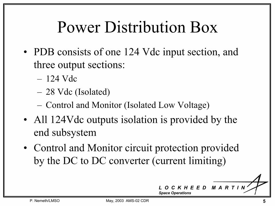
Power Distribution Box• PDB consists of one 124 Vdc input section, and
three output sections:– 124 Vdc – 28 Vdc (Isolated)– Control and Monitor (Isolated Low Voltage)
• All 124Vdc outputs isolation is provided by the end subsystem
• Control and Monitor circuit protection provided by the DC to DC converter (current limiting)

L O C K H E E D M A R T I N Space Operations
P. Nemeth/LMSO 6May, 2003 AMS-02 CDR

L O C K H E E D M A R T I N Space Operations
P. Nemeth/LMSO 7May, 2003 AMS-02 CDR
PDB
PDB Location

L O C K H E E D M A R T I N Space Operations
P. Nemeth/LMSO 8May, 2003 AMS-02 CDR
PDB

L O C K H E E D M A R T I N Space Operations
P. Nemeth/LMSO 9May, 2003 AMS-02 CDR
Cryomagnet Avionics Box (CAB)• Isolation for the 120Vdc line (feed thru from PDB) is
performed via DC to DC Converters • Cryomagnet Current Source• Magnet Charge/Discharge Circuit
– Persistent Switch– Shunt– Dump Rectifiers
• Cryomagnet Control Unit– Sensor Monitoring/Signal Conditioning– Cryomagnet Self Protection (CSP)– Uninterruptible Power Source (UPS)

L O C K H E E D M A R T I N Space Operations
P. Nemeth/LMSO 10May, 2003 AMS-02 CDR
Cryomagnet Avionics Box (CAB)
28 to 43 VdcDC to DC
Converters
PWM
PowerSwitch
Cryo Current Source (CCS)Semiconductor Switch
459 A1500 W
500 A100 mVShunt
120 Vdc1875 Wmax
From PDB
DumpRectifiers
CryomagnetSelf
Protection
120 Vdc
Valves/Heaters
Sensors
28V
dcfro
mP
DB
Cryomagnet Avionics Box (CAB)Cryomagnet
PersistentSwitch
UninterruptiblePower Source
DC to DCConverters
Hi-V IsolationDC to DCConverter
Hi-Voltage Isolation
MagnetController
Hi-VoltageIsolation

L O C K H E E D M A R T I N Space Operations
P. Nemeth/LMSO 11May, 2003 AMS-02 CDR
Dump Rectifiers• In the event that the magnet must be powered
down, the persistent switch will be opened to allow the current in the magnet to be dumped to a bank of 18 rectifiers (six sets in series of three rectifiers in parallel)
• These rectifiers will be protected by a cover to prevent incidental contact
• The rectifiers will be mounted on the two wake-side sill trunnion joints (large thermal mass)

L O C K H E E D M A R T I N Space Operations
P. Nemeth/LMSO 12May, 2003 AMS-02 CDR
Dump Rectifiers (cont.)• Worst case thermal analysis reveals that with a
continuous load rectifiers will maintain junction temps well below ratings even if one of a parallel series of three fail.
• Dump time is estimated at 80 minutes

L O C K H E E D M A R T I N Space Operations
P. Nemeth/LMSO 13May, 2003 AMS-02 CDR
Dump Rectifiers (Cont.)

L O C K H E E D M A R T I N Space Operations
P. Nemeth/LMSO 14May, 2003 AMS-02 CDR
Dump Rectifiers (Cont.)

L O C K H E E D M A R T I N Space Operations
P. Nemeth/LMSO 15May, 2003 AMS-02 CDR
Dump Rectifier Mounting Locations

L O C K H E E D M A R T I N Space Operations
P. Nemeth/LMSO 16May, 2003 AMS-02 CDR
Dump Rectifier Cover
Rectifier Cover
Access holeClose out plates

L O C K H E E D M A R T I N Space Operations
P. Nemeth/LMSO 17May, 2003 AMS-02 CDR
Cryomagnet Self Protection (CSP)• Designed for mission success purposes only, no
safety hazard• CSP circuitry is designed to identify a quench
condition in any individual coil and quench entire magnet evenly
• Redundant heater chains routed to alternating coils (either chain sufficient to quench magnet)
• Protects magnet by ensuring no magnet conductor deformation due to isolated heating, which could result in degraded performance
• The magnet structure will remain safe even if CSP circuitry does not function

L O C K H E E D M A R T I N Space Operations
P. Nemeth/LMSO 18May, 2003 AMS-02 CDR
CSP Functional Block Diagram
MAGNET TAP VOLTAGE(+/-15V) X 6
CHARGERBATTERY
CHARGERBATTERY
PWM CHARGE CTRL
PWM CHARGE CTRLGND
BAT1+
BAT1-
X 8 YARDNEYCELLS
CELLSX 8 YARDNEY
BAT2+
BAT2-
BAT.CHARGE1+
BAT.CHARGE2+
CHARGE1-BAT.
CHARGE2-BAT.
DISCHARGE2-BAT.
DISCHARGE2+BAT.
DISCHARGE1-BAT.
DISCHARGE1+BAT.
SSPC
CVTRDC/DC
STAT R TO N
STAT R TO R
+/-15V CSP N
+5V CSP N
(+/-15V CL N) X 4
CONTROLELECTRONICS
QUENCH
ON ONOFF OFF
FROM N FROM R DRIVERSN+24V HTR
HTR & VALVEN
QUENCHN
CONTROL N
CONTROL N
NOMINALHEATERCHAIN
BAT N+
BAT N+& VALVE
GND
(+/-15V CL R) X 4
+5V CSP R
+/-15V CSP RDC/DC
STAT R TO R
STAT R TO N
BAT R+
FROM N
OFF
CVTR
ON
FROM R
ON OFF
SSPCBAT R+
ELECTRONICSCONTROL
HTR & VALVE
& VALVE
QUENCHR
CONTROL R
DRIVERS+24V HTR R
CONTROL R
REDUNDANTHEATERCHAIN
R
QUENCH
SSPC
SSPC
SSPC
CVTRDC/DC
CVTRDC/DC
CVTRDC/DC
MAGNET TAP VOLTAGE(+/-15V) X 6
MAGNET TAP VOLTAGE(+/-15V) X 6
V N
RTN
RTN
V RBMS2
BMS1

L O C K H E E D M A R T I N Space Operations
P. Nemeth/LMSO 19May, 2003 AMS-02 CDR
Uninterruptible Power Source (UPS)
• The UPS will consist of a redundant set of batteries– Battery will provide control power during loss of
ISS power or communication to payload for mission success
• Watch-dog timer/control circuit• Normal Ramp down function• Quench monitoring• Initiation of quench, 45A pulse

L O C K H E E D M A R T I N Space Operations
P. Nemeth/LMSO 20May, 2003 AMS-02 CDR
UPS (Continued)– Battery will be designed to meet NSTS 1700.7B,
"Safety Policy and Requirements For Payloads Using the Space Transportation System", NSTS 1700.7B ISS Addendum, "Safety Policy and Requirements For Payloads Using the International Space Station", and JSC 20793, "Manned Space Vehicle Battery Safety Handbook“ and will be sized for a minimum of 8 hours of operation, plus ramp-down time

L O C K H E E D M A R T I N Space Operations
P. Nemeth/LMSO 21May, 2003 AMS-02 CDR
Cell Characteristics• Manufactured by Yardney/Lithion
– Prismatic cell– Dimensions: 95mm (3.74”) X 27.84mm
(1.096”) X 139.7mm (5.500”)– Weight: 900g (1.982 lbs)– Operational Temperature Range: -30 degC to
+50 degC

L O C K H E E D M A R T I N Space Operations
P. Nemeth/LMSO 22May, 2003 AMS-02 CDR
Battery Configuration

L O C K H E E D M A R T I N Space Operations
P. Nemeth/LMSO 23May, 2003 AMS-02 CDR
BMS Safety Inhibit Settings
100 µsec170A2-3 seconds80AOver Current
NoneNone3-4 seconds80 degCOver Temperature
200 µsec2.15V/cell3-4 seconds2.5V/cellOver-discharge
100 µsec4.3V/cell2-3 seconds4.2V/cellOver-charge
Hardware Delay
Hardware Limit
Software Delay
Software LimitParameter

L O C K H E E D M A R T I N Space Operations
P. Nemeth/LMSO 24May, 2003 AMS-02 CDR
CAB and UPS Mounting Locations
UPS
CAB

L O C K H E E D M A R T I N Space Operations
P. Nemeth/LMSO 25May, 2003 AMS-02 CDR
VacuumPump
Vacuum Line SFHe TankValve
BarometricSwitch
ControlElectronics (TBD)
J1553-STS(1553 RT28)
PDB
AMS-02
J422(RS-422)
I/F Panel A
PDAROEU
PDIPT0APCU1 & 2
StandardSwitchPanel
BFSGPC
Command
1553
Ku-Band
DDRS-2
RS-422
Power
120 Vdc 120 Vdc?124 Vdc28 Vdc
+5 VdcDiscrete
T
OIU 2PDI
PSP
Tx, Rx
3 TP12 awgPwr/Rtn
w/sensing(1 TP)
8 TSP22 awg
(4 TSP per)3 wire, 8 awgPwr/Rtn/Gnd
2 TP22awgPri/Red
1 TSP22awg
9TP (max)20 awg
Stub B1 TSP22 awg
1553 BusA & B
Pad & STS Interfaces Interconnect Diagram
I/F Panel A
Stub A1 TSP22 awg
P3 P4
J100
P100
J5
P5
J6
P6
J9
P9
J8
P8P1
J1
BC
JTBD JTBD
PTBD
PTBD PTBD
JTBD X 8
J1553-STS(1553 RT4)
P3 P4
BC
Stub B1 TSP22 awg
Stub A1 TSP22 awg
MLP B10Power/Data I/Fs
J4
P4
J3 J4 J3 J4

L O C K H E E D M A R T I N Space Operations
P. Nemeth/LMSO 26May, 2003 AMS-02 CDR
J1553-Z(1553)PDB
AMS-02
JFOM-A
4 TSP*16 awg
EVA I/F Panel
UMA
120 Vdc
Tx, Rx
3 wire, 8 awgPwr/Rtn/Gnd
ISS Interfaces Interconnect Diagram
J1553-Y(1553)
ISS 1553
BC
3 wire, 8 awgPwr/Rtn/Gnd
APS
HRDLFiber-Optic
Pair
HRDL
JFOM-B
EVAReplaceable
ACOP
Bus BRPCM-IIBus A
RPCM-II
HRDLFiber-Optic
Pair
** Loopbacks determine which module is powered.
Ku-Band
3 wire, 12 awgPwr/Rtn/Gnd
**
Bus Stub A,B/Address/Parity
8 TSP22awg
3 wire, 8 awgPwr/Rtn/Gnd
3 wire, 8 awgPwr/Rtn/Gnd
JLIF
6 TSP22awg
Address/Parity
1 TSP22awgStub B
1 TSP22 awgStub A
6 TSP22awg
Address/Parity
4 TSP*16 awg
P13 P14
Y_J1 Y_J2 Y_J3 Z_J1 Z_J2 Z_J3
J1
P19
J101B
P101
J101AJ104J103
P103P112P111
J112J111
J122 J121
SSRMS
PVGF
EBCS
To BCSHeaters
JPD
HRDLFiber-Optic
Pair
Tx, Rx
**
J-Crate
1 TSP22 awgStub A
1 TSP22awgStub B
J8 J11 J10 J13
J102
J100
P132
J131
P121P122
J75 J76
J132P131
J9
P9
J12 P12
P102
P8 P11 P10 P13
P100

L O C K H E E D M A R T I N Space Operations
P. Nemeth/LMSO 27May, 2003 AMS-02 CDR
Data System Components• Crate – Electronics Box• J-Crate – Performs Top Level DAQ, contains JMDCs, JLIF, and JHIF• JMDC – Main Data Computer – Combines Housekeeping data and Science data
for distribution, performs minor processing , combines pieces of event data into complete event, converts CAN and AMS Wire to 1553, RS422, and Fiber, also TRD Gas control and TTCS control.
• JBU – Buffer Unit – Contained within JMDC, 2GB buffer (1GB/hr)• JLIF – Low-rate data Interface – Transceivers for 1553• JHIF – High-rate data Interface – Fiber Interface and Transceivers for RS422 • USCM – Universal Slow Control Module – 8051 based CPU and O/S with
processing s/w (data gathering and blocking into types)• CDP – Common Digital Part – Gate Array, DSP, Memory,s/w code to
communicate on AMS Wire – performs digitizing, blocking and compression • CDDC – Command Distributor/Data Concentrator – Reads CDP
queue/combines pieces of single events, distributes commands to CDPs• AMS Wire – Hi-performance serial 100Mbps custom wire (similar to ESA
Space Wire)• LVDS – Low Voltage differential signal• JPD – J-Crate Power Distribution Box

L O C K H E E D M A R T I N Space Operations
P. Nemeth/LMSO 28May, 2003 AMS-02 CDR

L O C K H E E D M A R T I N Space Operations
P. Nemeth/LMSO 29May, 2003 AMS-02 CDR
Housekeeping Data Overview (equivalent to NASA H&S Data)
JMDC
JMDC
JMDC
JMDC
USCM
USCM
USCM
USCM
USCM
USCM
USCM
USCM
USCM
USCM
USCM
USCM
Dallas Temp Sensor Bus
LVDS (Digital Bus)
Analog In
SensorsSensors
SensorsSensors
SensorsSensors
SensorsSensors
SensorsSensors
SensorsSensors
SensorsSensors
Contained in J-Crate
Individual Experiment/Subsystem Crates
V, I, T, P, etc. fromdetectors/crates
CAN BusBus BBus A
JLIF
JHIF
1553 (STS)
1553 (ISS)
HRDL (ISS)
RS422 (STS)
CommandsData

L O C K H E E D M A R T I N Space Operations
P. Nemeth/LMSO 30May, 2003 AMS-02 CDR
Science Data
CDP
SensorsSensors
SensorsSensors
SensorsSensors
SensorsSensors
SensorsSensors
SensorsSensors
SensorsSensors
Contained in J-CrateIndividual Experiment/SubsystemBoxes
Detectors
CDP
CDP
CDP
CDP
CDP
CDP
CDP
CDP
CDP
SensorsSensors
SensorsSensors
SensorsSensors
CDDC
CDDC
CDDC
CDDC
CDDC
JMDC
JMDC
JLIF
JHIF
1553
RS422 to STS
Fiber to ISS
Primary CMD destinationfor sensor adjustment(remove biases, adjusthresholds, etc., byselecting node address)
DataCommand
AMS Blocks
AMS Blocks
Level 3 Trigger(software)
AMS Wire (Hi-performanceserial 100Mbps custom wire)
Level 1 Trigger(hardware)
JBU
JBU

L O C K H E E D M A R T I N Space Operations
P. Nemeth/LMSO 31May, 2003 AMS-02 CDR
AMS Resource Requirements• Power
– Average 2 kW– Max 2.3 kW
• Data– Science Data: 2 Mbps (avg)– Housekeeping Data: 2 kbps– Critical Health Data: 10 Bps

L O C K H E E D M A R T I N Space Operations
P. Nemeth/LMSO 32May, 2003 AMS-02 CDR
Data Compatibility Testing• STEP Testing (May 2003)• Taxiscope testing (June 2003)• 1553 RT Validation testing (June 2003)• APS testing at ISIL• OIU Lab Testing • ESTL testing – RS-422• PRCU testing at JSC• PTCS testing at KSC (during on-line processing)• Orbiter End to End Test

L O C K H E E D M A R T I N Space Operations
P. Nemeth/LMSO 33May, 2003 AMS-02 CDR
Power Compatibility Testing• Electrical Power Systems Laboratory (EPSL)
– Line-to-Ground Resistance & Independent Source Isolation• Inrush, Surge, Reverse, and Leakage Currents• Steady State Power
– Current Transients & Steady-state Levels– Compatibility with Flight Hardware or Emulators
• Soft Start/Stop• Current Limiting RPC
– Voltage Range & Transients• Normal/Abnormal• Ripple Voltage
– Large Signal Stability– Input Impedance / Gain & Phase Margins– Common Mode & Input Isolation

L O C K H E E D M A R T I N Space Operations
P. Nemeth/LMSO 34May, 2003 AMS-02 CDR
EMC Testing• Conducted Emissions
– SSP 30237, Rev F• CE01, CE03, CE07
• Conducted Susceptibility– SSP 30237, Rev F and SSP 30237 SSCN 3282 D.2
• CS01, CS02, and CS06
• Radiated Emissions– SSP 30237, Rev F, RE02
• Radiated Susceptibility– SSP 30237, Rev F
• RS02 and RS03PL (SSCN 3282 PIRN 57003-NA-0023)