Embed Size (px)
Citation preview

ee
.9
Avid® Maestro™ | LivUser Guid
Version 2019

n
e
t
is e is a is ,
t.
Legal Notices
Product specifications are subject to change without notice and do not represent a commitment othe part of Avid Technology, Inc.
This product is subject to the terms and conditions of a software license agreement provided with thsoftware. The product may only be used in accordance with the license agreement.
This product may be protected by one or more U.S. and non-U.S patents. Details are available awww.avid.com/patents.
This document is protected under copyright law. An authorized licensee of may reproduce thpublication for the licensee’s own use in learning how to use the software. This document may not breproduced or distributed, in whole or in part, for commercial purposes, such as selling copies of thdocument or providing support or educational services to others. This document is supplied as guide for . Reasonable care has been taken in preparing the information it contains. However, thdocument may contain omissions, technical inaccuracies, or typographical errors. Avid TechnologyInc. does not accept responsibility of any kind for customers’ losses due to the use of this documenProduct specifications are subject to change without notice.
Copyright © 2019 Avid Technology, Inc. and its licensors. All rights reserved.

Contents
1.Using this Guide.............................................................................. 7Symbols and Conventions ....................................................................8If You Need Help.................................................................................8Avid Training Services .........................................................................8
2.Introduction ..................................................................................... 9What is Maestro | Live? .....................................................................10
Workflow......................................................................................10System Requirements........................................................................11
3.Getting Started..............................................................................12Starting Maestro | Live ......................................................................13
Server Messages ...........................................................................14The Maestro | Live Production Window.................................................15
Maestro | Live Menus.....................................................................16The Device Bar .............................................................................20Tools Icons...................................................................................20Workspace Tools ...........................................................................20Local Preview Tools .......................................................................20
Control and Widget Tools ...................................................................21On-Air and Edit Modes .......................................................................22
Edit Mode.....................................................................................22On-Air Mode .................................................................................23
Layout: Panels and Widgets ...............................................................24Containers: Tabwidget and Group....................................................25
Saving Your Work .............................................................................26Archiving a Production ...................................................................27Saving Controls.............................................................................28
4.Devices .............................................................................................29Render Unit Manager.........................................................................30
Unloading Graphics........................................................................32Connecting Devices .......................................................................32
Data Source Manager ........................................................................33Indirect Database Configuration ......................................................34Configuring a Database ..................................................................34

Advanced XML Data Source ............................................................36GPIO Manager ..................................................................................38
Simulating a GPIO Device...............................................................40Automation Mediator Manager ............................................................41Data Stream Manager........................................................................45Clip Server Manager ..........................................................................48Graphic Control Manager....................................................................51Router Control Manager .....................................................................54ShotBox Manager..............................................................................57
5.Controls............................................................................................59Production Controls ...........................................................................60
The Control Manager......................................................................61Action Controls .................................................................................62
Actions – The Details Tab ...............................................................62Actions – The Graphic Item Tab.......................................................66Workspace ...................................................................................77Actions – The Data Tab ..................................................................83
Pacer Controls ..................................................................................86Pacers – The Graphic Item Tab........................................................86Pacers – Data Tab .........................................................................87Pacers – Lines Tab.........................................................................88
Data Groups.....................................................................................89Filtering a Data Group....................................................................90Editing a Data Group .....................................................................91
GPIO Controls ..................................................................................94Playlist Controls ................................................................................94Automation Mediator Controls.............................................................95Data Streamer Controls .....................................................................96Clip Viewer Controls ..........................................................................97ShotBox Controls ............................................................................ 100Control Tools.................................................................................. 103
6.Widgets ......................................................................................... 104Widgets ......................................................................................... 105Widget Properties ........................................................................... 106
Textbox Properties ...................................................................... 106Label Properties .......................................................................... 106Combobox Properties ................................................................... 107Check Box .................................................................................. 108Spinbox ..................................................................................... 108

File Selection .............................................................................. 109Slider......................................................................................... 109Conversion Table......................................................................... 110Time.......................................................................................... 111Image........................................................................................ 111
7.Productions ................................................................................. 112Creating a Production ...................................................................... 113Using If-Then Commands................................................................. 113Playing Animations.......................................................................... 115Running Tickers .............................................................................. 116Playing Scenes ............................................................................... 117Playing Other Controls ..................................................................... 118
8.Databases..................................................................................... 119Using a Database............................................................................ 120
9.Playlists.......................................................................................... 122Advanced Playlist Controls ............................................................... 123
Playlist Menu .............................................................................. 124Events Menu............................................................................... 124Tools Menu................................................................................. 125Advanced Playlist Settings ............................................................ 126
Building a Playlist............................................................................ 136Scheduling Individual Events......................................................... 137Tied Events ................................................................................ 137Groups....................................................................................... 138Playlist Rule Builder ..................................................................... 139Playlist Validation ........................................................................ 140
Legacy Playlist Controls ................................................................... 142Running a Basic Playlist from an Automation System........................ 148Logging Playlist Events................................................................. 150Metadata tab .............................................................................. 151Building an Automation Playlist ..................................................... 152
Automatic Event Creation................................................................. 154
10.Setting Preferences ................................................................ 155Application..................................................................................... 156Server........................................................................................... 157

Control Behavior ............................................................................. 159Plugins .......................................................................................... 161Storage ......................................................................................... 162Redundancy ................................................................................... 163Hotkeys......................................................................................... 164Media Asset Management................................................................. 165
11.Working with MediaCentral | Asset Management ...... 167Introduction ................................................................................... 168Activating a Connection to MediaCentral | Cloud UX............................. 168Connecting to and Browsing MediaCentral | Cloud UX Files ................... 168
12.AAF File Support ..................................................................... 171What is AAF and its usage in Maestro | Live........................................ 172
AAF in Media Composer................................................................ 172Prerequisites for using AAF files in Maestro | Live............................. 173Displaying AAF Files in Maestro | Live............................................. 175
13.Browser....................................................................................... 176Using the Browser........................................................................... 177Rendering Graphics as a Clip ............................................................ 179Browser Menus ............................................................................... 181Customizing the Layout ................................................................... 182Maestro | Live Browser Settings........................................................ 184
Appendix.......................................................................................... 187Browser Services ............................................................................ 188
Configuration.............................................................................. 188API Documentation...................................................................... 189
Available CallByName Commands...................................................... 202

1. Using this Guide
In this section:
Symbols and Conventions on page 8
If You Need Help on page 8
Avid Training Services on page 8

8
1. U
sin
g th
is G
uid
e
Symbols and Conventions
This symbol marks a step-by-step procedure.
NOTE:A note specifies useful or optional information, relevant to the preceding text.
TIP:A tip provides useful information on shortcuts, or how to do things differently.
Bold text marks a part of the GUI, such as a menu item, dialog box name, or GUI button. For example, “click OK”.
ALL CAPITALS text specifies a keyboard key. For example, “press CTRL and drag the name...”.
If You Need Help
If you are having trouble using your Avid product:
1. Check the latest information that might have become available after the documentation was published:
You should always check online for the most up-to-date documentation because the online version is updated whenever new information becomes available. To view the online versions, visit the Knowledge Base at www.avid.com/support.
2. Check the documentation that came with your Avid application or your hardware for maintenance or hardware-related issues.
3. Visit the online Knowledge Base at www.avid.com/support. Online services are available 24 hours a day, 7 days a week. Search this online Knowledge Base to find answers, view error messages, to access troubleshooting tips, download updates, and read or join online message-board discussions.
Avid Training Services
Avid makes lifelong learning, career advancement, and personal development easy and convenient. Avid understands that the knowledge you need to differentiate yourself is always changing, and Avid continually updates course content and offers new training delivery methods that accommodate your pressured and competitive work environment. For information on courses/schedules, training centers, certifications, courseware, and books, please visit www.avid.com/support and follow the Training links, or call Avid Sales at 800-949-AVID (800-949-2843).
Symbols and Conventions |

2. Introduction
This chapter provides an overview of Maestro | Live. It contains the following sections:
What is Maestro | Live? on page 10
System Requirements on page 11

10
2. I
ntr
od
uct
ion
What is Maestro | Live?
Graphics and video play major roles in today’s live production. Presenting captivating and—most importantly—meaningful content that relates to every second of the action is a challenge. Maestro™ | Live makes real-time production easy with an all-in-one, data-driven UHD graphics, augmented reality, and video playout solution that boosts efficiency like never before. It’s a game-changer for all live coverage.
Workflow
Maestro | Live creates productions using graphic templates authored in Maestro | Designer.
In Maestro | Live you define devices and controls as the basis of your production. Maestro | Live uses a production file as the convention for saving your work for future use.
Devices are hardware or software modules that are used to play graphics to air, such as a render unit, a GPIO device, a database, etc.
Maestro | Live controls are tools for controlling graphics, data display, GPIO triggering, etc.
Production files can be divided into panels to reflect stages of production, control types, or any other division required.
All controls are saved separately within a production folder. Controls can be used and re-used within the same production (across panels) or in different productions.
What is Maestro | Live? |

2. In
trod
uctio
n
System Requirements
System specifications for a Maestro | Live Control PC:
• Microsoft Windows® 10
• Intel Core i7 7th generation or comparable Xeon CPU processor
• 16 GB RAM or more
• NVIDIA GeForce GTX 1050 2GB or above
• 500 GB SSD drive
• 24" 1920x1080 resolution capable monitor
System specifications for a Maestro | Live Database Server:
• Microsoft Windows Server 2016
• Dual Xeon E5 processor
• 32 GB RAM
• 2 x 1GB Ethernet interfaces
• 500GB 7200 RPM HDD
• 2 free USB ports
• Dual power supply
• Additional software: Microsoft SQL Server 2016 Standard or Enterprise Edition (with the appropriate license dimensioning for the project).
NOTE:Please note, that a dual servers setup should include a storage cabinet with at least 8 TB of effective storage.
System Requirements | 11

3. Getting Started
This chapter provides general information on using Maestro | Live and an overview of the Maestro | Live GUI in the following sections:
Starting Maestro | Live on page 13
The Maestro | Live Production Window on page 15
Layout: Panels and Widgets on page 24
Saving Your Work on page 26

3. G
etting Started
Starting Maestro | Live
Maestro | Live is opened from the Start menu in Avid > Maestro | Live.
You can also use the shortcuts placed on the desktop during installation, as shown below.
To start Maestro | Live:
1. Start the Maestro | Live Server.
The Maestro | Live Server Controller opens.
NOTE:In order to work with the Maestro | Live client, the Server Controller must be open and the service must be running.
2. Click Start to start the server.
3. If required, change the StartUp Type definition, and set the other options, as described here:
Startup Type
Change how the server will start, the next time you open the Server Controller.Manual - Allows you to open the Maestro | Live Server Controller without starting the server. (You can start it manually after the Controller is opened.)Automatic - Automatically starts the Server when you open the Maestro | Live Server Controller.
Starting Maestro | Live | 13

14
3. G
etti
ng
Star
ted
4. Once the Server Status is “Running”, start the Maestro | Live Client.
A splash screen is displayed, and then the Login window opens.
5. Enter the required parameters as follows.
NOTEAfter the initial startup, you can set Maestro | Live to start without displaying this dialog box. For more information, see Automatic Login on page 156.
6. Click Connect.The Maestro | Live Client opens.
Server Messages
The Maestro | Live Server Controller displays messages in the Server Messages tab, that can help you understand the current status of the server, or explain errors.
These messages are saved to a log, and can be sent to Avid for support, if required.
Service Log
Specify the name and path of the log file for the current session.Create new file when service starts - When this check box is selected, a new log file is created for each session. If the check box is cleared, The file Server.log is overwritten.
Always on top
Select this check box if you want the Maestro | Live Server Controller visible at all times (regardless of the active window). This option is useful if you want the server messages visible (see Server Messages on page 14). To allow the Maestro | Live Server Controller to run in the background, clear the check box.
Server Host Host name or IP address of the computer on which the server is installed.
NOTE:The name “localhost” is used when the Maestro | Live Server and Maestro | Live Client are installed on the same computer.
Root Folder Set the location for the production storage.
Starting Maestro | Live |

3. G
etting Started
The Maestro | Live Production Window
The Maestro | Live Production window allows access to all of Maestro | Live’s menus, functions, and windows.
The Maestro | Live Production Window | 15

16
3. G
etti
ng
Star
ted
Maestro | Live Menus
The following sections provide information on the Maestro | Live menus.
File Menu
New Open a new production.
Open Open a browser window, to select a previously saved production.
Save Save the current production in the default directory, as defined in the application settings (see Storage on page 162).For more information, see Saving Your Work on page 26.
Save As Open a browser window, to save the production under a new name (in the location set in the settings window, see Storage on page 162).For more information, see Saving Your Work on page 26.
Recent Productions
List of the five most recently opened productions.
Import from production file
Open a browser window to import a production.
Export to production file
Open a browser window, to save a production to be used on a different workstation. When exporting a production, it is saved in a single file.
Merge with Production
Open a browser window, to open another Maestro | Live production into the current production. If no production is currently open, the content of the saved production is opened as a new, unnamed production
Import and Merge Production
Opens browser window, to open another Maestro | Live production into the current production. If no production is currently open, the content of a saved production is opened as a new, unnamed production
Search Open a dialog box to search for controls in all productions (available when using a MS SQL database for storage).
Archive Open a dialog box with various options for creating a zipped archive of the current production and scenes.For more information, see Archiving a Production on page 27.
Switch User Open a dialog box to login with a different user name, for different user privileges (available when using a MS SQL database for storage).
Exit Close the Maestro | Live Client.
The Maestro | Live Production Window |

3. G
etting Started
Panel Menu
Controls Menu
New Create a new production panel, providing a new workspace within the current production.For more information, see Layout: Panels and Widgets on page 24.
Rename Open the Rename Panel dialog box, allowing you to change the name of the panel.
Remove Delete the current production panel permanently from the production. (Controls are still available in the Control Manager. In order to remove them, enable the checkbox next to “Remove and delete controls from production”).
Load to All Renders
Load all graphics in the current panel to their defined render unit devices. The Loading Status window is displayed.
Stop All Stop all controls in this panel. Note that by default this option does not unload graphics that are already playing.
Control Manager
Toggle the Control Manager. For more information, see The Control Manager on page 61.
Action Add an Action control to the production in the current panel.For more information, see Action Controls on page 62.
Pacer Add an Pacer control to the production in the current panel.For more information, see Pacer Controls on page 86.
Data Group Add an Data Group control to the production in the current panel.For more information, see Data Groups on page 89.
GPI/O Control
Add a GPIO control to the production in the current panel to allow you to configure which controls are triggered by GPIO keys.For more information, see GPIO Controls on page 94.
Playlist Add a Playlist control to the production in the current panel.For more information, see Legacy Playlist Controls on page 142.
Automation Mediator
Add an Automation Mediator control to the production in the current panel to allow Maestro | Live to communicate with external automation systems.For more information, see, Automation Mediator Controls on page 95.
Data Streamer
Add a Data Streamer control to the production in the current panel to allow Maestro | Live to stream data from an external source.For more information, see Data Streamer Controls on page 96.
Advanced Playlist
Add an Advanced playlist control to the production in the current panel.For more information, see Advanced Playlist Controls on page 123.
Clip Viewer Add a Clip Viewer control to the production in the current panel to list all clips available on a specified video server.For more information, see Clip Viewer Controls on page 97.
The Maestro | Live Production Window | 17

18
3. G
etti
ng
Star
ted
Devices Menu
Tools Menu
Shotbox Add a Shotbox control. For more information, see ShotBox Controls on page 100.
Render Unit Manager
Open the Render Unit Manager to display render unit devices, and add, configure, or remove render units, and to unload scenes from the selected render unit.For more information, see Render Unit Manager on page 30.
Data SourceManager
Open the Data Source Manager to set the database connections.For more information, see Data Source Manager on page 33.
GPI/O Manager
Open the GPIO Manager to display General Purpose Input/Output devices, and to add, configure, or remove devices.For more information, see GPIO Manager on page 38.
Automation Mediator Manager
Open the Automation Mediator Manager to list and edit Automation Mediator controls.For more information, see Automation Mediator Manager on page 41.
Data Stream Manager
Open the Data Stream Manager to display data stream devices, and to add, configure, or remove devices.For more information, see Data Stream Manager on page 45.
Clip Server Manager
Open the Clip Server Manager to display clip servers, and to add, configure, or remove devices.For more information, see Clip Server Manager on page 48.
Graphic Control Manager
Open the Graphic Control Manager to display graphic control devices, and to add, configure, or remove devices.For more information, see Graphic Control Manager on page 51.
Router Control Manager
Open the Router Control Manager to display routers, and to add, configure, or remove devices.For more information, see Router Control Manager on page 54.
ShotBox Manager
Open the ShotBox manager to display, add, configure or remove ShotBox devices. For more information, see Router Control Manager on page 54.
Customize Set these options for GUI usability (selected options are marked with ):Snap to Grid - When this option is selected, controls are snapped to an invisible grid, for more controlled placement and scaling. Dock Elements - When this option is selected, controls are snapped to one another in the workspace.Show Hotkeys - When this option is selected in the Tools menu, the Hotkey defined for the control is displayed on the control.For more information, see Hotkeys on page 164.Show Inputs - Toggle the Inputs list.
Settings Open the Application settings dialog box.See Setting Preferences on page 155.
The Maestro | Live Production Window |

3. G
etting Started
On Air Menu
Metadata Settings
Open a dialog box, to set different metadata options. Available only when using an SQL database. For more information, see Creating Metadata on page 64.
Languages Set the GUI language from the available options. User defined names set in one language remain unchanged.You can create your own GUI translation files by copying and renaming one of the XML files in the \Client\Languages directory, and entering your own text.
Global Parameters Viewer
Open the Global Parameters Viewer, to view and change the current values of the defined global parameters.For more information, see Global Parameters on page 82.
Properties XXX
Inputs XXX
Widget Box XXX
Preview Manager
XXX
Media Asset Management
Open the Media Asset Management panel. For more information, see Connecting to and Browsing MediaCentral | Cloud UX Files on page 168.
Playlist Creator
Use this rule manager to create playlist events when certain automation commands are received. For more information, see Automatic Event Creation on page 154.
Connect All Connect all application devices, such as render units, databases, GPIO devices, etc.
NOTE:Some devices, such as the Data Source device, are better to remain not connected.
Disconnect All Disconnect all application devices.
Load All Load the entire production to the defined render units. The Loading Status window is displayed.
Stop All Actions Stop all controls. (This option, by default does not unload graphics that are already playing.)
Local Preview Window
Open the local Preview window.This option is available when the local preview option is enabled in the Render Unit Manager on page 30.
Lock All Prevent clients from changing the controls layout.
The Maestro | Live Production Window | 19

20
3. G
etti
ng
Star
ted
The Device Bar
The Device bar, displayed at the bottom of The Maestro | Live Production Window (see page 15), shows all devices that have been defined, and their status (green when connected, red when disconnected).
Click the device name to display options for the device, depending on its type. For example, here you have the option of starting or stopping the RenderEngine (RE) application for a device.
Tools Icons
The Tools displayed in the lower right corner of The Maestro | Live Production Window on page 15, allow you to set the following workspace preferences:
Workspace Tools
These Tools are displayed in the lower left corner of the Production Window.
Local Preview Tools
The following Local Preview playout tools are available:
Show Hotkeys
Click this icon to toggle the display of the hotkey on the controls in the production. Only defined hotkeys are displayed.For more information, see Hotkeys on page 164.
Storage status
This icon is marked green when the current storage is connected, or red when there is a connection issue. If there is a connection problem, Maestro | Live displays a message to that effect, and continually tries to reconnect.
Redun-dancy
Start a redundancy for this client. The icon is marked green when a redundancy client is running, or red when there is no redundancy client running.For more information, see Redundancy on page 163.
Snap to Grid
Click this icon to toggle the snap to grid setting.
Dock Elements
Click this icon to toggle docking.
PVW Cue Click this icon to cue.
PVW Play
Click this icon to play.
PVW Stop
Click this icon to stop.
The Maestro | Live Production Window |

3. G
etting Started
Control and Widget Tools
The following control and widget tools are available:
Edit Click this icon to edit the control.
Cue Click this icon to cue the control.
Play Click this icon to play the control.
Stop Click this icon to stop playing the control.
Make a copy
Click this icon to make a copy of the element (available for widgets and controls).
Make a link
Click this icon to make a link between two controls.
Remove Click this icon to remove the element (available for widgets and controls).
Control and Widget Tools | 21

22
3. G
etti
ng
Star
ted
On-Air and Edit Modes
Maestro | Live comes with two built-in work modes:
• Edit - in this mode you can build your own UI for any sports, production or operational need. Clicking on an element on the panel marks it for editing.
• On-Air - switch to this mode for execution of your controls. Clicking on a control, executes Cue and carries out its script.
Edit Mode
In the Edit mode, it is possible to create new panels, and fill them with controls and widgets organized into groups and tab widgets.
The Widget Box is accessible from the left Sidebar (available only in the Edit mode), offering UI elements (mostly used controls and all input widgets) that can be dragged and dropped into the working panel. Each element can be easily scaled to the required size.
The right Sidebar can contain up to 6panels:
NOTE:Each panel (Widget Box and the four side panels) can be docked on left side, right side or can be undocked. They are not required to be on their default sides.
• Input - lists all GI parameters for the selected control for which the Show in Inputs window window setting is selected, with the option to change the value of the GI parameter, according to the type set when creating the GI parameter.
• Properties - shows all editable parameters for the currently selected element.
• Global Parameters - lists all Global Parameters of the production. You can remove this side panel from the Sidebar by clicking on the button. To add it back to the Sidebar, go to Tools > Global Parameters Viewer...
• Control Manager - displays a list of all controls that have been saved on the server and are linked to the current production, in order to provide a
On-Air and Edit Modes |

3. G
etting Started
comprehensive list when working in a multi-panel production. You can remove this side panel from the Sidebar by clicking on the button. To add it back to the Sidebar, go to Controls > Control Manager.
You can also pin the side panel to the workspace by clicking on button. To unpin it,
click on the button.
On-Air Mode
Once the controller creation is complete, you can switch to the On-Air mode.
The Widget Box is no longer available, and the Sidebar does not contain the Parameters panel.
A Cue action is carried out after a single left mouse click on a control. The control’s query is executed and parameters assigned.
Input Widgets can also be edited with a single mouse click.
On-Air and Edit Modes | 23

24
3. G
etti
ng
Star
ted
Layout: Panels and Widgets
The Maestro | Live workspace can be divided for work in a number of ways.
The panels are available for convenient organization of production controls, and you can add as many panels as required, when you run out of workspace, or when you want to separate controls for any reason. Panels can reflect stages of production, types of controls, etc., as required.
Panels are distinguished by tabs at the top of the workspace.
Container widgets (Tabwidget and Group) can be used anywhere for organization of controls and input widgets. Use the Group widget to place the controls in one area, or use the Tabwidget to put them in a tabbed view.
A single control can be available on all panels by creating a shortcut to the control (see Production Controls on page 60).
To create a new panel:
1. Select Panel > New.
The Layout Editor is displayed.
2. Type in a Name for your new panel.
3. Click OK.
A new panel is created in the production.
NOTE:When you close a panel, you have the option of removing all controls in the panel, or keeping them within the production.
To arrange a panel:
1. Add a control or widget to the panel in one of the following ways:
• Drag the control or widget from the Widget Box.
• Add controls from the Controls menu.
2. Put the controls and input widgets inside a container widget for better organization.
3. After the element has been placed on the panel, it remains selected to allow for resizing or moving it to a new position. When moving an elements, a “snap to” line is shown to present how the element is aligned to other widgets and controls.
NOTE:You can move controls and widgets on the panel using the keyboard arrows. Select one or more elements (with CTRL key) and using the arrows place them in a new position. With the Snap to Grid option enabled, a single move is 5 pixels. With this option disabled, one move is 1 pixel.
Layout: Panels and Widgets |
3. G
etting Started
Containers: Tabwidget and Group
A container is a visual organizational aid. It is not significant if a control or widget is placed within a container, or somewhere in a panel. Container widgets do not have UIDs, and cannot be called, referenced, etc.
To add a container:
■ Drag the chosen Container widget from the Widget Box > Containers.
■ To rename or resize the container, select it on the panel and click on the Properties button in the Sidebar.
To set how Tabwidgets are displayed:
1. Select the Tabwidget on the panel and click on the Properties button in the Sidebar.
The Properties of the Tabwidget are displayed.
2. Name the Tabwidget.
3. Set the Layout as required.
Tabbed Display the sub-tabs within the container in a tabbed view.
Collapsible Display the sub-tabs within the container in a collapsible view.
Layout: Panels and Widgets | 25

26
3. G
etti
ng
Star
ted
Saving Your Work
In Maestro | Live, each project is saved as a production file containing the panels you set, and pointers to the controls used in the production. Controls are saved separately in a folder within the production file structure, with the same name. The structure location is initially set during installation.
You can store productions in a file-folder system or in an MSSQL database. Only database storage gives you the option of assigning metadata in productions.
To save a production:
1. Select File > Save, and type a name for the production.
2. Click OK.
The production is saved in the default location.
To rename a production:
■ Select File > Save As, and rename the production.
To change the storage location (for future saves):
■ See Storage on page 162
Saving Your Work |

3. G
etting Started
Archiving a Production
You can archive a production and all files related to the production as a zipped file, to allow moving productions from one computer to another that doesn’t share a Projects folder, or storage.
To archive a production:
1. After saving your production, select File > Archive.
The Archive dialog box opens.
2. Under Archive List Content, select the elements you want to zip.
3. Set the compression level of the archive.
4. Click Create archive list, and verify that all required files are in the list.
You can clear any check box to omit an item from the archive.
5. Click Archive, and browse to the location in which you want to save the .zip file.
6. If required, you can save the archive list in a separate file, by clicking Save archive list.
Maestro | Live Storage
Archive all productions saved in the Maestro | Live file storage base. (Available only when using file storage.)
Production Archive the production and all of its controls. (Available only when using file storage.)
Scenes Archive the Maestro | Designer project folder containing the scenes used in the current production.
Inputs Archive all files referred to in the production.
Saving Your Work | 27

28
3. G
etti
ng
Star
ted
NOTE:To open an archived production on a new computer, extract the files to the G:\ drive, using the Extractor tool located in C:\Program Files\Avid\MaestroLive\<version>\Client\Tools.
Saving Controls
Maestro | Live provides the following options for saving controls as files:
• In the default location, as part of the production, as described above.
• In the general Actions directory (not the production Actions folder), while maintaining a link from the current production to the control. This makes the control accessible to any production, and it can be changed from any production. (See Exclude from production on page 63.)
• In the general Actions directory (not the production Actions folder), with no link to the production, so that when a different production uses the control, it is actually using a copy of the original, with a different UID.
To save a control separately, with a link to the production:
■ In the control’s Details tab, select the Exclude from Production check box, and specify the location in which to save the control.
See Exclude from production on page 63.
A link from the production to the control is maintained.
To save a control independently:
1. In the Production window, right-click the control to display the graphic menu, and click Save (see Save as on page 61).
Or-
In the control’s Editor, click Save.
A browser window opens at the general Action folder.
2. Click OK.
The control is saved independently of the current production (with no link).+
Saving Your Work |

4. Devices
In Maestro | Live, the term “device” refers to any external module that is required in order to air graphics. This includes hardware modules, such as HDVGs and GPIO devices, and software modules, such as databases and automation system connections.
All devices are listed in the Device Bar (see The Device Bar on page 20), and can be manipulated from there.
This chapter describes how to set up a device to use in Maestro | Live, in the following sections:
Render Unit Manager on page 30
Data Source Manager on page 33
GPIO Manager on page 38
Automation Mediator Manager on page 41
Data Stream Manager on page 45
Clip Server Manager on page 48
Graphic Control Manager on page 51
Router Control Manager on page 54
ShotBox Manager on page 57
NOTE:A green icon in the listed devices indicates a connected device. A red icon indicates a disconnected device.

30
4. D
evic
es
Render Unit Manager
The Render Unit Manager allows you to define the devices to which Maestro | Live sends graphic commands. You can set up multiple devices to work simultaneously, as required, and you can unload all graphics that are loaded to a channel.
To open the Render Unit Manager:
■ From the Devices menu, select Render Unit Manager.
To define a new render unit:
1. In the Render Unit Manager (Devices > Render Unit Manager), click Add.
The Add device dialog box opens.
Render Unit Manager |

4. D
evices
2. Enter the following parameters, as described below.
3. Click OK.
The device is added to the list of channels in the Render Unit Manager.
To edit or remove a device:
1. In the Render Unit Manager (Devices > Render Unit Manager), in the Graphics Channel list, select a device.
2. Click Edit or Remove, as required.
Name Set the name used to identify the device/channel.
UID Set the Unique ID that the device uses. If you do not assign a UID, one is assigned automatically.
NOTE:UIDs are the label by which a Maestro | Live device/control is identified to all other devices and controls. It is recommended not to change a UID once it has been set.
Type Select the type of the device: Render Unit for Render Engine, or Render Unit / Unreal for Unreal Engine.
Address Set the IP Address of the HDVG.
Port Set the device communication port. For Unreal Engine, set the port to 8890.
Render OS Set the type of operating system used by the rendering unit.
Canvas ID Set the ID of the canvas as defined in the RenderEngine settings (optional).
Use as Preview
Select this check box to open a RenderEngine Preview window.Choose Local to open a window within the Maestro | Live application window (and set the Address to localhost), or Remote to use a remote output device.
Preview window as separate window
Select this check box if you want the Render Engine Preview window defined in Use as Preview to open in an external window, outside of the Maestro | Live application.
Log Level Set what device operations are logged. The higher the level, the more information will be logged. (Off=lower, Verbose=higher).
Event Level
Set the frequency of communications between the server and client for the purpose of updating the GUI. The higher the level, the more frequently the GUI is updated. This may be at the expense of response time, therefore, the log level can be lowered or set to OFF.
Render Unit Manager | 31

32
4. D
evic
es
Unloading Graphics
To unload graphics from a device:
1. In the Render Unit Manager (Devices > Render Unit Manager), in the Graphics Channel list, select a device from which to unload graphics.
2. Select the scene(s) to unload or click Select All.3. Click Unload.
The graphics/scenes are unloaded from the selected device.
Connecting Devices
Devices can be connected or disconnected in the Render Unit manager.
To connect/disconnect a device:
1. Select the device in the Render Units list.
2. Click Connect or Disconnect, depending on the device’s original state (RenderEngine must be running).
NOTE:A device’s state can be changed in the Production window, as well. In the The Device Bar, right-click the device, and choose the required option.
Render Unit Manager |

4. D
evices
Data Source Manager
The Data Source Manager is used for setting up database connections. Maestro | Live can connect to the following database types:
Direct connections:
• Microsoft Excel
• Microsoft Access
• MSSQL
• XML
• XML Advanced
• Euroleague
• Text
• Flowgic
Indirect connections (using the ODBC Data Source Administrator or dedicated connectors):
• MySQL
• Oracle
• IBM DB2
• ODBC DSN
To open the Data Manager:
■ From the Devices menu, select Data Manager.
Data Source Manager | 33

34
4. D
evic
es
Indirect Database Configuration
For Oracle and MySQL databases, you must set up the server via the ODCB Data Source Administrator before you can set up a device in the Data Manager.
To set up the server:
1. On your computer, open the Control Panel (Start > Control Panel).2. Open Administrative Tools > Data Sources (ODBC).
3. The ODBC Data Source Administrator opens.
4. In the User DSN tab, click Add.
5. Select the following:
For MySQL - Microsoft ODBC version 3.51 or 5.1 driver
For Oracle - Microsoft OleDB for Oracle driver
Configuring a Database
To set up a new database connection in Maestro | Live:
1. In the Data Source Manager (Devices > Data Source Manager), click Add.
The Add device dialog box opens.
Data Source Manager |

4. D
evices
2. Enter the following parameters, as described below:
3. Click OK.
The dialog box is closed and you are returned to the Data Manager.
4. Click Test to verify that the data source is set up properly.
In the Data manager you can also connect, disconnect, and reset the connection, by selecting the database, and using the appropriate buttons.
Name The name used for this data source. This name appears in the Device bar and the Data Manager.
UID The Unique ID that Maestro | Live uses for this device. If you do not assign a UID, one is assigned automatically.
NOTE: UIDs are the label by which a Maestro | Live device/control is identified to all other devices and controls. It is recommended not to change a UID once it has been set.
Source Type
From the list, select the type of database. The following fields in this table are enabled or disabled, depending on the selected type.
Source Name
When available, enter the path and file name of the required database.
Database Name
When available, enter the name of the database.
User When available, enter the user name for the database connection.
Password When available, enter the password for the database connection.
Port Number
When available, enter the number of the port to which the database is connected.
Always Connected
When this check box is enabled, the database connection is maintained as long as Maestro | Live is open, for quick access.When this check box is cleared, the database connection is open only when required. This requires login to be performed each time the connection is opened.
Log Level This determines what device operations are logged. The higher the level, the more information will be logged. (Off=lower, Verbose=higher).
Event Level
This determines the frequency of communications between the server and client for the purpose of updating the GUI. The higher the level, the more frequently the GUI is updated. This may be at the expense of response time, therefore, the log level can be lowered or set to OFF.
Data Source Manager | 35

36
4. D
evic
es
Advanced XML Data Source
The XML Advanced data source allows to preview the content of the source file and perform SQL operations directly in the Add/Edit device windows.
To set up a new Advanced XML database in Maestro | Live:
1. In the Data Source Manager (Devices > Data Source Manager), click Add.
The Add device dialog box opens.
2. Enter a Name for your data source.
3. Select XML Advanced as the Source Type.
4. If required, set a user name and password to access the file.
5. In the Source Name field, enter the path to or browse for the XML file.
Once the file is loaded, a preview is generated on the right-hand side. Use the Refresh button next to the path name to reload the preview.
6. You can enable automatic update and reloading of the file:
• when the source file has been modified;
• or using a timer and defining a time interval.
7. Define your tables, as described below:
• Double-click on New Table to set a different name.
• In the Node Path field, enter the path to (or drag from the Preview) the XML node, which indicates what is the main target of the table. Click on Find to check the entered path and look for the available columns.
Data Source Manager |

4. D
evices
• Each column has a unique ID and a path to a node from the XML file. Columns can be added by dragging a node from the XML Previewer (a column can be created from an ancestor, a descendant or an attribute). Some columns are created automatically after entering the Node Path. You need to make sure that all column IDs are unique.
• Use the Validate path button to checks if a table can be created from the specified columns.
8. Click OK to save the new source.
The dialog box is closed and you are returned to the Data Manager.
9. Click Test to verify that the data source is set up properly.
Example:
You can use your newly created XML advanced data source to fill the contents of a Data Group control.
1. Make sure that the data source is connected.
2. Add a new Data Group control to your panel and go to Data Editor by pressing on
the button.
3. In the Query section, select the newly created data source from the Data Manager.
4. You can query the source using all types of SQL queries. You can choose which columns should be displayed using the ‘Select’ query, and filter the content by adding the ‘where’ condition.
If you want to create a table from rows with a specific attribute, use an XPath syntax. E.g.: Node Path -> /bookstore[1]/book[@lang='eng'] will build a database with rows that have the attribute 'lang' set to 'eng'.
Use the 'JOIN' syntax to build a query from different tables
Data Source Manager | 37

38
4. D
evic
es
GPIO Manager
Maestro | Live is capable of communicating with a GPIO (General Purpose Input/Output) device in order to trigger controls mechanically. A GPIO control can have up to 16 GPIO channels to coincide with the mechanical unit’s controls.
Define and configure the connections to GPIO devices in the GPIO Manager.
To open the GPIO Manager:
■ From the Devices menu, select GPIO Manager.
NOTE:When using a GPIO device, the Adlink 7256 driver must be installed first, and tested with the Adlink test application.
To define a GPIO device:
1. In the GPIO Manager (Devices > GPIO Manager), click Add.
GPIO Manager |

4. D
evices
The Add Device dialog box opens.
2. Enter the following parameters, as described below.
3. Click OK.
The device is added to the list of devices in the GPIO Manager.Setting the commands triggered by the GPIO controls is done in Maestro | Live in a GPIO control. To create a control for the GPIO device, see GPIO Controls on page 94.
Name The name you want to use to identify the GPIO device.
UID The Unique ID that Maestro | Live uses for the GPIO device. If you do not assign a UID, one is assigned automatically.
NOTE:UIDs are the label by which a Maestro | Live device/control is identified to all other devices and controls. It is recommended not to change a UID once it has been set.
Card ID Assign GPIO cards a unique ID when using multiple GPIO cards.
Polling Interval
Define, in milliseconds, how often the GPIO device state is read by Maestro | Live.
Refresh Display Interval
Define, in milliseconds, how often Maestro | Live updates status changes in the display.
Type From the list, select the type of GPIO device to be used. Each device required the correct hardware and drivers to be installed.
Log Level This determines what operations are logged. The higher the level, the more information will be logged. (Off=lower, Verbose=higher).
Event Level
This determines the frequency of communications between the server and client for updating the GUI. The higher the level, the more frequently the GUI is updated. This may be at the expense of response time, therefore, the log level can be lowered or set to OFF.
GPIO Manager | 39

40
4. D
evic
es
Simulating a GPIO Device
You can simulate a GPIO device to test the settings in a GPIO control. For this, you must create a GPIO control (see GPIO Controls on page 94) and assign it to a device.
To simulate a GPIO device:
1. In the GPIO Manager select the device to which you assigned the control.2. Set the parameters as follows:
3. Click Send Signal to simulate the GPIO triggering.
4. Click Close to close the Simulate GPIO dialog box.
“Send signal” triggers an action (In) or external device (out).
Signal Type From the list, select source and destination of the signal; from the GPIO device to Maestro | Live (IN) or from Maestro | Live to the GPIO device (OUT).
Index From the list, select the number of the GPIO button.
State From the list, select the state of the GPIO button; pressed (ON) or released (OFF)
GPIO Manager |

4. D
evices
Automation Mediator Manager
Maestro | Live can be controlled by an Automation system using multiple CII, VDCP, and USC protocols.
Setting Up an Automation Mediator
In the Automation Mediator manager, you can set up, edit, or remove a connection to an external automation system.
To open the Automation Mediator Manager:
■ From the Devices menu, select Automation Mediator Manager.
To define a new automation mediator:
1. In the Automation Mediator Manager (Devices > Automation Mediator Manager), click Add.
Automation Mediator Manager | 41

42
4. D
evic
es
The Automation Mediator Device Editor opens.
2. Enter the following parameters, as described below.
Name The name used to identify the automation mediator.
UID The Unique ID that Maestro | Live uses for this automation mediator. If you do not assign a UID, one is assigned automatically.
NOTE:UIDs are the label by which a Maestro | Live device/control is identified to all other devices and controls. It is recommended not to change a UID once it has been set.
Stop answering PING when Render Unit is not connected
Select this check box to stop sending ping confirmations, in order to indicate to the automation system that a rendering unit is offline.
Automation Mediator Manager |

4. D
evices
Stop answering PING when no control is assigned to automation device
Select this check box to stop sending ping confirmations, when there are no controls assigned to this automation device.
Respond “OK” to all triggering commands
Select this check box to send an “OK” response to the automation system when CUE/PLAY triggering commands are received (without executing the commands). When cleared, CUE/PLAY commands are executed.
Connection Type Set the automation protocol type. The parameters vary for each type.
TC Server Host Set the host of the Timecode server for frame accuracy features.
TC Server Port Set the port of the Timecode server for frame accuracy features. (default=20202)
TC Offset Set the offset to compensate for the expected delay set the automation system.
Auto Cue Response
On- Maestro | Live automatically sends a positive response when a cue command is received from automation system.Off - Maestro | Live sends a response based on system status when a cue command is received from automation system.
Respond to Non-Supported commands
Set the default system response upon receiving an unknown command.
CII Display Mode Support
Set an alternate mode for Maestro | Live’s response when a Cue command is received. When this option is set to ON, Cue executes Play. When set to VALIDATE, Cue validates incoming commands.
Control name for Cue/Play
Define the default Maestro | Live name to be used as the VDCP ID for Cue and Play commands.
Control name for Stop
Define the default Maestro | Live name to be used as the VDCP ID for Stop commands.
Cue Play Mode Set the system to process Cue and Play commands only, without sending a response.
Stop Control (already playing) on new Play command
Stop a currently playing control upon receiving a new Play command.
Stop Control (already cued) on new Cue command
Stop the currently Cued control when receiving a new Cue command.
Character Mode Select the communication character set.
Automation Mediator Manager | 43

44
4. D
evic
es
3. In the Advanced tab, set the following options
4. Click OK.
The device is added to the list of channels in the Automation Mediator Manager.In order to use this device, you must have an Automation Mediator control. For more information, see Automation Mediator Controls on page 95.
To disconnect or remove a device:
1. In the Automation Mediator Manager (Devices > Automation Mediator Manager), in the Devices list, select a device.
2. Click Disconnect to disconnect the automation system from Maestro | Live,
3. Click Remove to remove the device from the Automation Mediator Manager.
Port Type Set the port type. Definable port settings change according to the port type selected here.
Port Set the communication port number.
UID Prefix Type a prefix to add to each UID received from the automation system.
UID Suffix Type a suffix to add to each UID received from the automation system.
Communica-tion Log Level
Select the log entry type to be included in the log.
Log Level This determines what device operations are logged. The higher the level, the more information will be logged. (Off=lower, Verbose=higher).
Event Level This determines the frequency of communications between the server and client for the purpose of updating the GUI. The higher the level, the more frequently the GUI is updated. This may be at the expense of response time, therefore, the log level can be lowered or set to OFF.
Automation Mediator Manager |

4. D
evices
Data Stream Manager
Here you can set up an external data source for real time data to be streamed instantly into a production in RenderEngine.
The Render Unit can be used as streaming device as well, allow you to stream the current clip name, clip status, ticker name, and ticker status. The Data Stream control is used as a direct channel for instantly conveying data from external sources to your production and can be linked to a Live Export in the Render Unit.
Maestro | Live can connect to the following streaming protocols:
• SwissTiming - Swimming Calypso
• SwissTiming - Swimming OSM6
• SwissTiming -Athletics
• NauNet UK130
• System6 - Swimming
• Lynxs Time (simplified)
• Lynxs Result (simplified)
In this version, the Render Unit can be used as streaming device as well, allowing streaming of the current clip name, clip status, ticker name and ticker status.
Setting Up a Data Stream
To open the Data Stream Manager:
■ From the Devices menu, select Data Stream Manager.
Data Stream Manager | 45

46
4. D
evic
es
To add a new Data Stream:
1. In the Data Stream manager, click Add.
The Add Device dialog box is displayed.
2. Enter the following parameters, as described below.
Name The name used to identify the data stream.
UID The Unique ID that Maestro | Live uses for this data stream. If you do not assign a UID, one is assigned automatically.
NOTE:UIDs are the label by which a Maestro | Live device/control is identified to all other devices and controls. It is recommended not to change a UID once it has been set.
Protocol Type
Set the protocol type from the list of available protocols.
Character Mode
Set the character encoding for the text to be displayed.
Port Type Currently, only serial ports can be used.
COM Set the COM port.
Baud Rate Set the number of symbols per second to be transmitted via Maestro | Live.
Data Bits Set the allowed number of data bits in each character.
Data Stream Manager |
4. D
evices
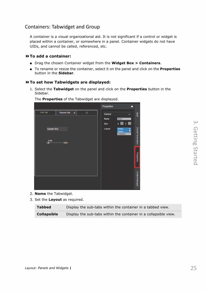
3. In the Advanced tab, set the following:
4. Click OK.
The device is added to the list of data streams.
Stop Bits Select One, OnePointFive, or Two stop bits to send at the end of every character allow the receiving signal hardware to detect the end of a character and to re-synchronize with the character stream.
Parity Set the parity bit to add in each character to None, Odd, or Even.
Flow Control Set data transmission to be controlled by Hardware handshake signal or XonXoff software signal, or Off for no flow control.
Log Level This determines what device operations are logged. The higher the level, the more information will be logged. (Off=lower, Verbose=higher).
Event Level This determines the frequency of communications between the server and client for the purpose of updating the GUI. The higher the level, the more frequently the GUI is updated. This may be at the expense of response time, therefore, the log level can be lowered or set to OFF.
Data Stream Manager | 47

48
4. D
evic
es
Clip Server Manager
Clips are stored on a Clip Server for use in Maestro | Live. Clips are played using a dedicated clip engine and board, independent of the graphics engine and board.
Setting Up a Clip Server
In the Clip Server manager, you can define clip storage locations.
To open the Clip Server Manager:
■ From the Devices menu, select Clip Server Manager.
To add a new Clip Server:
1. In the Clip Server manager, click Add.
Clip Server Manager |

4. D
evices
The Add Device dialog box is displayed.
2. Enter the following parameters, as described below.
Name Set the name used to identify the clip server.
UID Set the Unique ID that Maestro | Live uses for this clip server. If you do not assign a UID, one is assigned automatically.
NOTE:UIDs are the label by which a Maestro | Live device/control is identified to all other devices and controls. It is recommended not to change a UID once it has been set.
Device Type Set the type of clip server: Video Engine or OVS.
IP Address Set the IP address of the clip server computer.
Port Set the port through which Maestro | Live communicates with the clip server.
Cue time Set the time for the Video engine to load a clip (if a shorter time is specified in the playlist), before the system returns an error.
Storage Set the storage type; if the clips are stored in a Native (standard) file structure, or if they are Stored in an IBIS MAM database.
Host Set the name of the clip server computer.
DB Name Set the name of the clip database.
Clip Server Manager | 49

50
4. D
evic
es
3. Click OK.
The device is added to the list of clip servers.
User Name When available, enter the user name for database connection.
Password When available, enter the password for database connection.
Allow Clip Transfer
Select this check box to allow clips to be transferred from the clip server to the rendering system, and set the Source path, Destination path, and the Default clip format.
AAF files folder
Set the location of the AAF files to be used by the clip server device;For more information, see What is AAF and its usage in Maestro | Live on page 172.
Show Player Select this check box to enable the Player view in the Clip Viewer control. In the Browse folder window, you can enter a path for a video clips folder not registered in the Video Engine database. The folder needs to be shared and accessible by everyone and it must be mounted on the Video Engine Linux machine. For more information, see Clip Viewer Controls on page 97.
Log Level This determines what device operations are logged. The higher the level, the more information will be logged. (Off=lower, Verbose=higher).
Event Level This determines the frequency of communications between the server and client for the purpose of updating the GUI. The higher the level, the more frequently the GUI is updated. This may be at the expense of response time, therefore, the log level can be lowered or set to OFF.
Clip Server Manager |

4. D
evices
Graphic Control Manager
Graphic Controls are independent rendering systems that can be controlled from Maestro | Live.
Setting Up a Graphic Control
In the Graphic Control Manager, you can define graphic controls.
To open the Graphic Control Manager:
■ From the Devices menu, select Graphic Control Manager.
To add a new graphic control:
1. In the Graphic Control manager, click Add.
Graphic Control Manager | 51
52
4. D
evic
es
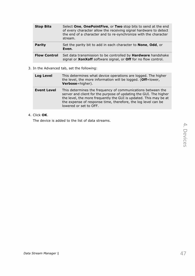
The Add Device dialog box is displayed.
2. Enter the following parameters, as described below.
Name Set the name used to identify the graphic control rendering system.
UID Set the Unique ID that Maestro | Live uses for this graphic control. If you do not assign a UID, one is assigned automatically.
NOTE:UIDs are the label by which a Maestro | Live device/control is identified to all other devices and controls. It is recommended not to change a UID once it has been set.
Device Type Set the type of graphic control: Harris G7 or Maestro | Live.
Character Mode
Select the communication character set.
Port Type Set the port type. Definable port settings change according to the port type selected here.
Port Set the communication port number.
Log Level This determines what device operations are logged. The higher the level, the more information will be logged. (Off=lower, Verbose=higher).
Graphic Control Manager |

4. D
evices
3. Click OK. The device is displayed in the Graphic Control Manager.
Event Level This determines the frequency of communications between the server and client for the purpose of updating the GUI. The higher the level, the more frequently the GUI is updated. This may be at the expense of response time, therefore, the log level can be lowered or set to OFF.
Graphic Control Manager | 53

54
4. D
evic
es
Router Control Manager
Router Controls connect to existing routers to control sources and destinations.
Setting Up a Router Control
In the Router Control Manager, you can define routers.
To open the Router Control Manager:
■ From the Devices menu, select Router Control Manager.
To add a new graphic control:
1. In the Router Control manager, click Add.
Router Control Manager |

4. D
evices
The Add Device dialog box is displayed.
2. Enter the following parameters, as described below.
Name Set the name used to identify the router control rendering system.
UID Set the Unique ID that Maestro | Live uses for this router control. If you do not assign a UID, one is assigned automatically.
NOTE:UIDs are the label by which a Maestro | Live device/control is identified to all other devices and controls. It is recommended not to change a UID once it has been set.
Device Type Set the type of router control: Pro-Bel, BlackMagic Videohub, Evertz Quartz, Imagine or NVision NV9000 (standard or mnemonic).
Character Mode
Select the communication character set.
Port Type Set the port type. Definable port settings change according to the port type selected here.
Port Set the communication port number.
Log Level This determines what device operations are logged. The higher the level, the more information will be logged. (Off=lower, Verbose=higher).
Router Control Manager | 55

56
4. D
evic
es
Event Level This determines the frequency of communications between the server and client for the purpose of updating the GUI. The higher the level, the more frequently the GUI is updated. This may be at the expense of response time, therefore, the log level can be lowered or set to OFF.
Router Control Manager |

4. D
evices
ShotBox Manager
ShotBox provides an easy button interface with Maestro | Live. You can assign playable controls, such as actions, pacers and playlists to ShotBox LCD keys for quick access.
Setting Up a ShotBox device
In the ShotBox Manager, you can define ShotBox devices.
To open the ShotBox Manager:
■ From the Devices menu, select ShotBox Manager.
To add a new ShotBox:
1. In the ShotBox manager, click Add.
ShotBox Manager | 57

58
4. D
evic
es
The Add Device dialog box is displayed.
2. Enter the following parameters, as described below.
Name Set the name used to identify the ShotBox device.
UID Set the Unique ID that Maestro | Live uses for this ShotBox device. If you do not assign a UID, one is assigned automatically.
NOTE:UIDs are the label by which a Maestro | Live device/control is identified to all other devices and controls. It is recommended not to change a UID once it has been set.
Host Enter the IP address of the ShotBox device.
Port Set the communication port number (default: 40010).
Log Level This determines what device operations are logged. The higher the level, the more information will be logged. (Off=lower, Verbose=higher).
Event Level This determines the frequency of communications between the server and client for the purpose of updating the GUI. The higher the level, the more frequently the GUI is updated. This may be at the expense of response time, therefore, the log level can be lowered or set to OFF.
ShotBox Manager |

5. Controls
This chapter describes how to set up a control in Maestro | Live in the following sections:
Production Controls on page 60
Action Controls on page 62
Pacer Controls on page 86
Data Groups on page 89
GPIO Controls on page 94
Playlist Controls on page 94
Automation Mediator Controls on page 95
Data Streamer Controls on page 96
Clip Viewer Controls on page 97

60
5. C
on
tro
ls
Production Controls
When you add new controls to a production, the control is represented graphically. Each control determines the data sent to a device, and the output that is displayed.
To create a control:
■ From the Controls menu, select a control type to add to the current panel.
Or-
Drag the control from the Widget Box and drop it onto the panel.
To copy an existing control:
■ Select the control on the panel and click on Make a copy on the Control Toolbar.
or
■ Press CTRL and drag the control to a new position in the panel.
A new control is created, disconnected from the source control (with a new UID).
Action Add an Action control to the current panel that allows you to create graphics and animation-related macros.For more information, see Action Controls on page 62.
Pacer Add a Pacer control to the current panel that allows you to create macros for tickers and other elements that require repetition.For more information, see Pacer Controls on page 86.
Data Group Add a Data Group control to the current panel to display a predefined database.For more information, see Data Groups on page 89.
GPIO Control
Add an GPIO control to the current panel that allows you to configure which the Maestro | Live controls are triggered by GPIO keys.For more information, see GPIO Controls on page 94.
Clip Viewer Add a Clip Viewer control to the current panel to display the clip storage.For more information, see Clip Viewer Controls on page 97.
Advanced Playlist
Add an Advanced Playlist control to the current panel that allows you to build a playlist referring all controls and clips that you want to run during a broadcast with a scheduler.For more information, see Playlists on page 122.
Data Streamer
Add a Data Streamer control to the current panel that acts as an open channel for transmitting external data.For more information, see Data Streamer Controls on page 96.
Automation Mediator
Add an Automation Mediator control to the current panel that allows Maestro | Live to communicate with external automation systems.For more information, see Automation Mediator Controls on page 95.
Production Controls |

5. C
on
trols
To create a shortcut to a control:
■ Select the control on the panel and click on Make a link on the Control Toolbar.
or
■ Press ALT and drag the control to a new position in the panel.
A shortcut is created to the source control (with the same UID, so that both controls
are played together).
The Control Manager
The Control Manager displays a list of all controls that have been saved on the server and are linked to the current production, in order to provide a comprehensive list when working in a multi-panel production (see The Maestro | Live Production Window on page 15).
To display the Control Manager:
■ Select Controls > Control Manager.Or-
Open the Control Manager from the Sidebar.
The following options are available when right-clicking on a control
Hotkeys Opens the Hotkeys dialog box, allowing you to set the hotkeys to Select or to Select & Play the current control.For more information, see Hotkeys on page 164.
Save as Opens a browser window, allowing you to save the control outside of the current production.For more information, see Saving Controls on page 28.
Load Opens a browser window, allowing you to load a previously saved control in place of the current control.
Refresh Refreshes the control by reading the current state of the control from the server. (For controls used by more than one production.)
Update Data Available only for a Pacer control. Refreshes the data read from the defined database.
Remove Opens a dialog box that allows you to choose to remove the control from the current panel or to remove the control (and all shortcuts with the same UID) completely from the panel and the production.
Cue Cues the selected control.
Play Plays the selected control to the defined device.
Stop Executes all commands placed in the Stop tab (in the control editor).
Edit Opens the Editor for the current control and allows you to edit the control parameters.
Details Opens a Details window that allows to change the Name, UID or Appearance of the control.
Production Controls | 61

62
5. C
on
tro
ls
From the Control Manager, you can create copies of existing controls (Press CTRL and drag the control to the required panel), or create shortcut controls to the controls already in the list. (Press ALT and drag the control to the required panel.)
You can filter the controls displayed by entering characters in the case-sensitive Filters field. When this field is empty, all controls are displayed.
Action Controls
The Action control is a versatile control that is a basic unit in Maestro | Live. When you add an Action control to a production, you can set it up to carry out any sequence of commands, as required.
To edit an Action:
■ Right-click the action control, and select Edit.The Action Editor window opens with the Details tab displayed.
Set up the control as described in the following sections.
Actions – The Details Tab
In the Details tab of the Action Editor, you can name the control, assign a unique ID and a render unit for airing anything defined in this control, as follows.
Details
Action Name
Define the name that is displayed on the control.To use an identical action name and UID, click the Link icon before entering the action name.
Action Controls |

5. C
on
trols
To assign the render unit to which the control graphics are sent:
■ In the Devices list, select the required render unit.
UID A unique identifier that Maestro | Live uses for this control only. If the UID is not linked to the action name, and you leave this field empty, the system assigns a UID automatically.
NOTE:UIDs are the label by which a Maestro | Live device/control is identified to all other devices and controls. It is recommended not to change a UID once it has been set.
Display - display the UID underneath the control or hide the UID (None).
Exclude from production
Allows you to save the control independently of the production, in the specified directory.For more information, see Saving Controls on page 28.
Appearance
Lock Aspect Ratio
Select this check box to keep the proportions of the control image constant.
Image Path Browse to an image to apply to the control. Set the Opacity of the image.
Image Size Set the size of the image applied to the control.
Image Align
Select alignment of the image within the control.
Control Size
Set the size of the action control.
Color Set the color of the control.
Font Set the font face and properties for displaying the control name.
Text Align Set the alignment of the text within the control.
Action Metadata
Metadata is available only when working with an MSSQL database.
Advanced Set up advanced logging options for the control, other than what you set in the Application Settings dialog box.
Action Controls | 63

64
5. C
on
tro
ls
Creating Metadata
NOTE:Metadata is available only when working with an MSSQL database.
Metadata can be added manually or filled in automatically in Maestro | Live for better search and sort capabilities. Any Control or Event can have defined metadata.
To add metadata:
1. In the Tools menu, select Metadata Settings.
A dialog box opens.
The default metadata fields are displayed in bold letters.
2. Edit or add a field as required:
a. Set the Type of metadata field to be displayed in the Control Editor.
Text Metadata with alphanumeric format.
Numeric Metadata with numeric value.
Dropdown Create a list from which to add metadata.
Checkbox Metadata in the form of a true/false value.
Autofill Create a string that will be created automatically from the data you define here
Action Controls |

5. C
on
trols
b. Set the Properties of the field.
c. Under Assign to assets, select the control types which will display the metadata field that you defined.
d. Click OK.
5. The metadata field is now displayed for all selected control types.
Text Limit the number of characters allowed in a text field. (Maximal number of characters is 1000.)
Numeric Set the minimal and maximal values allowed in a numeric field, as well as the incremental value, and the spaces after the decimal point.
Dropdown Determine the items in the list to choose from, as required.
Checkbox Add a check box, with a descriptive label.
Autofill Define the data to be added to the string; choose from the control information and existing metadata fields to create an automatic string for each control. Set a separator to appear between each datum.
Action Controls | 65

66
5. C
on
tro
ls
Actions – The Graphic Item Tab
The Graphic Item tab in the Action Editor, is where you define what actions will be performed when you play the control, as described in the following sections.
Command List
The Commands list, on the left, contains internal commands that are carried out within Maestro | Live (unrelated to an external device), and Render Unit commands that are carried out on their assigned device.Internal commands
API Commands
Call by Name
Used for entering any API commands (that are not listed in the Maestro | Live command list) supported by Maestro | Live. Target UID - leave the default or use the UID of a target control.Command - enter the required command. For a list of possible commands, see Available CallByName Commands on page 202.Data - enter a value to be displayed as data, if required.Data Delim. - enter the symbol that acts as a separator between data items. You can use any character (except space), however it is important not to use characters that might be a part of the data value.Assign to – assign a returned response from the server to a global or GI parameter.
Control Set Name
Allow the current control to change the name of a different control.Control UID – enter the UID of the target control.Value - enter the text to be applied to the target control.
Control Set Image
Allow the current control to change image within a different control.Control UID – enter the UID of the target control.Image Path - enter the image path or browse for the image to be applied to the target control.
Action Controls |

5. C
on
trols
Control Set Color
Allow the current control to assign a color to a different control.Control UID – enter the UID of the target control.Color - enter the color to be applied to the target control. Colors can be entered in 3 ways: full hex (#000000), shortened hex (#000) or with predefined names (black).
Control Play
Allow the current control to play a different control.Control UID – enter the UID of the target control.For more information, see Playing Other Controls on page 118.
Control Play + Data
Allows the current control to play a different control, containing specified data from a database.Control UID – enter the UID of the target control.Data – enter the value to be displayed as data. If you enter more than one value (using a deliminator), the first values are sent to the defined keys, and the following values are sent to the GI parameters that are defined as automation types.Data Deliminator – enter the symbol that acts as a separator between data items. You can use any character (except space), however it is important not to use characters that might be a part of the data value.For more information, see Playing Other Controls on page 118.
Control Stop
Stop playing any referenced control.
Calculator Use a global parameter to calculate values for internal use. See Global Parameters on page 82.Target name – the global parameter to where the calculated result is sent.a – A variable that takes its value from a global parameter or is entered here.operator – from the list, select the calculating operator, as follows:• Addition (+), subtraction (-), multiplication (x), division (/).• % – calculate what percent a is of b (e.g.,
5% 10 = 50).• ^ Power of.• Abs - use an absolute number in place of input value (e.g.,
-2=>2). Does not require a value in b.• Int - use integer in place of input value (e.g., 1.8=>1). Does not
require a value in b.• IntRand - use a random integer between the defined limits (a
and b) in place of the input value.• Modulo – calculate the remainder of a divided by b (e.g., 13
Modulo 5 = 3).• Rand - use a random number between the defined limits (a and
b) in place of the input value.• Round - round the input value to the closest integer (e.g.,
1.8=>2). Does not require a value in b.b – enter a value or the value of another global parameter, to be applied.
Internal commands
Action Controls | 67

68
5. C
on
tro
ls
Command-line
Used for operational, Windows-oriented instructions to the computer on which the Maestro | Live client is running.
Convert Convert one time-format to another; from <GI para> timecode, milliseconds, frames, seconds.
Execute Script File
Execute external Java or Visual Basic script. This command allows you to utilize Java or Visual Basic commands that are not available in Maestro | Live.
Group Group a series of commands for easier access, and for referencing as a group. Click the V/> symbol to toggle the display of the grouped commands.It is recommended to group commands of the same purpose\type and to name the group appropriately for viewing and working.
Block Group a series of commands for synchronized execution. Click the V/> symbol to toggle the display of the commands.
If Create a logical if-then statement.For more information, see Using If-Then Commands on page 113.
Select Run one or more groups of statements using if-then logic, depending on the value of expressions.
While Continuously run a group of commands while a condition is valid. The condition is verified continuously, unless you define a “wait”.
Label Used for creating a label.
Pause Create a pause in play until Play is clicked again for the current control. Other controls can be played during a pause.
Set GI Parameter
Set the value of a GI parameter, to replace the value previously defined in the parameter.
Set Global Parameter
Set the value of a global parameter, to replace the value defined when creating the parameter.Can be used to replace a global parameter value with a GI parameter value.Can be used to create a new global parameter.
Remove Global Parameter
Remove the global parameter from the list of global parameters.
Sound Play Set a file name to play a sound on the Maestro | Live client computer (e.g., as an alert).
Sound Stop (This command requires a prior Sound Play command.)Stop playing the sound.
Wait Set a limited pause in the play, in milliseconds.
File Man-agement
Set validated files used in the production to be locked to prevent any changes.
Execute Query
Set a query to be executed at any stage of the control playout.
Internal commands
Action Controls |

5. C
on
trols
Render Unit Commands
Render Engine
Animation
Anim. Play Play an animation.Animation – from the Scene View tab, drag the required animation to this field. Scene – automatically takes the value of the Scene ID given when defining the animation.
Anim. Continue
Continue an animation (that contains programmed stops), once.Animation – from the Scene View tab, drag the required animation to this field. Scene – automatically takes the value of the Scene ID given when defining the animation.
Anim. Rewind
Rewind the animation to the first frame.Animation – from the Scene View tab, drag the required animation to this field. Scene – automatically take the value of the Scene ID given when defining the animation.Stop Anim. – when this check box is selected, the animation stops after rewinding to the first frame. When this check box is cleared, the animation is rewound, then played out.
Anim. Stop Stop the animation. Requires a prior Anim.Play or Anim.Continue command.Animation – from the Scene View tab, drag the required animation to this field. Scene – automatically take the value of the Scene ID given when defining the animation.
Anim. Break Loop
Stop a looped animation at the end of a cycle.
Anim. Get Duration
Get duration of animation in frames from RE.
Anim. Start at Frame
Play an animation from a specified frame.Animation – from the Scene View tab, drag the required animation to this field. Scene – automatically take the value of the Scene ID given when defining the animation.Frame# – the number of the frame at which to start the animation.,Stop Anim. – when this check box is selected the animation stops at the specified frame. When this check box is cleared, the animation is played from the specified frame until the end or as specified in the script.
Anim. Set Speed
Set the speed at which the animation is played.Animation – from the Scene View tab, drag the required animation to this field. Scene – automatically take the value of the Scene ID given when defining the animation.Speed (number) – 1=the speed set in the original animation, 2=twice the original speed, etc.
Action Controls | 69

70
5. C
on
tro
ls
Keyframe Change
Change the position on the timeline of a keyframe defined in an animation to change its duration.Animation – from the Scene View tab, drag the required animation to this field. Scene – automatically take the value of the Scene ID given when defining the animation.Channel – must be taken from the “Channel name” field in Key Editor in Maestro | Designer. Remove the animation name from the beginning of the string (e.g.:Transformation#Rectangle#Position#X). Keyframe – use the keyframe name assigned in Maestro | Designer.Field – current or new position (time) of the keyframe.Value – new (required) value of field.
Scene
Send Export Used to send values to be displayed in a predefined export.Live check box – When this check box is selected, manual entries in Value are updated in the preview in real time. When the check box is cleared, the value is display only after the control is played.Scene – automatically takes the value of the Scene ID given when defining the export.Export – from the Scene View tab, drag the required export to this field. Value – enter the data to be displayed; this can be done manually, or by dragging the value of a GI or global parameter to this field.Type – select the required data type from the list.
Scene Load Load the specified scene to the DVG.
Scene Unload Unload the specified scene from the DVG.
Scene Activate
Used to display a scene (a graphic template) that does not contain animations, tickers, exports, etc.Scene – the scene ID value.Vslot - specify the Vslot on which to display the scene.
Scene Deactivate
Vslot - specify the Vslot from which to clear the scene.
Scene Deactivate All
Deactivate all scenes that were previously activated, in all Vslots.
Clips
Render Engine
Action Controls |

5. C
on
trols
Clip Cache Cache a specified video file in the Render Unit memory before playing. It is recommended to place this command in the Cue tab.Path – path and file name of the required clip.Alpha – specifies if the clip contains an alpha channel.Interlaced – specifies if a clip was exported with interlacing enabled.Repeat – the number of times to play the clip.Sync Master – specifies if the clip should be synchronized with an audio clip.Group – enter the name assigned to group the video and audio clips (when Sync Master is selected).Audio Channel – if synced with an audio clip, or if clip includes audio, define the audio channel on which the clip will be played.
Clip Uncache Remove a specific clip from the HDVG memory.Specify Path and file name.
Uncache All Clips
Remove all clips from the Render Unit memory.
Audio Clip Cache
Cache an audio clip.This command should be placed in the Cue tab.Path – Browse to and select the audio clip.render unit – the render unit to which you want to load the audio clip. (For example, when using channel branding firmware, use numbers 1-16).Repeat – the number of times you want to repeat the audio clip.Group – enter the name assigned to group the video and audio clips (when Sync Master is selected in the Clip Cache command).
Audio Clip Play
Play an audio clip.
NOTE:In order to play an audio clip, the clip must be included in the Maestro | Designer scene as an object with a clip texture applied. Both the clip texture and the Play parameter must have exports. The clip texture parameters in Maestro | Designer should be "Is Video" for video, or "Is Audio" for audio (or both).
File Export – from the Scene View tab, drag the required clip texture export to this field. Scene – automatically take the value of the Scene ID given when defining the export.Play Export – from the Scene View tab, drag the required clip Play export to this field. Clip Filename – clip location (full path).
Audio Clip Stop
Scene – automatically take the value of the Scene ID given when defining the export.Play Export – from the Scene View tab, drag the required clip Play export to this field.
Render Engine
Action Controls | 71

72
5. C
on
tro
ls
Audio Recall Preset
The HDVG can have up to eight audio presets. Here you can specify what preset to use when playing an audio clip.Name – the number of the preset.Transition time – define the time (in seconds) to transition from one audio preset to another.
Audio Reload Presets
Load audio presets XML file to RenderEngine.
Render Unit
Render Unit Must place at least two Render Unit commands and define different devices. The commands are executed simultaneously on the defined devices, allowing you to play the same scene with different data.
Send Global Export
Set the value of a global export.Global exports allow changing RE parameters that are not directly related to a scene. Global exports are defined in an XML file (GlobalExports.xml) delivered with RE. Export attributes must be defined: the name, which is the export’s UID, and the target address (class type, ID, parameter name) which is changed when RE receives a new export value.
HDVG Route Set the type of signal sent from each output connector on the S/HDVG.Output – select the output connector.Source – select the signal type.
Internal Mixer Enable the internal mixer to use the internal linear keyer of the Render Unit platform.
Pre Multiply Use – select this check box to enable rendering of half-transparent pixels on the video background correctly. It is recommended to use this option only when required, since pre-multiplying reduces image quality.Relevant only when internal mixer is in use.
Start RenderEngine
Start RenderEngine.
Stop RenderEngine
Stop RenderEngine.
Render to Image
Take a snapshot of the display screen and saves it as specified. Must be saved on G:/.
Bypassing
Set Bypass Define if a bypass device is enabled (to have a backup feed ready, in case the main feed is disrupted by a power failure). Requires an installed bypass device.Use – select True from the list to enable the bypass function, or False to disable it.
WatchDog Set Set the delay after which the WatchDog device takes control of the S/HDVG.
Render Engine
Action Controls |

5. C
on
trols
Unreal Engine
Unreal Engine Commands
WatchDog Route
Set the WatchDog device to control the output of RenderEngine.
WatchDog Recover
Start the WatchDog device’s recovery sequence.
Interactive Commands relevant to interactive (touchscreen) controls.Applicable when licensed.
Ticker
Ticker A container for grouping all ticker related commands.
Ticker Start Play a ticker. Ticker Name – from the Scene View tab, drag the required ticker to this field. Scene – automatically takes the value of the Scene ID given when defining the animation.
Ticker Stop Stop the ticker. Stop Style – select how the ticker is stopped; immediately, after the currently shown item, or after entire ticker runs.
Ticker Continue
Continue playing the ticker after a programmed stop. Ticker Name – from the Scene View tab, drag the required ticker to this field. Scene – automatically takes the value of the Scene ID given when defining the animation.
Ticker Set Speed
Set ticker speed. Ticker Name – from the Scene View tab, drag the required ticker to this field. Scene – automatically takes the value of the Scene ID given when defining the animation.Speed – set the ticker speed.
Ticker Set Offset
Set the offset between the items in the ticker.Ticker Name – from the Scene View tab, drag the required ticker to this field. Scene – automatically takes the value of the Scene ID given when defining the animation.Offset – sets the offset between ticker items in RE units.
Animation
UnReal Anim. Play
Play an animation.Animation – from the Scene View tab, drag the required animation to this field. Scene – automatically takes the value of the Scene ID given when defining the animation.
Render Engine
Action Controls | 73
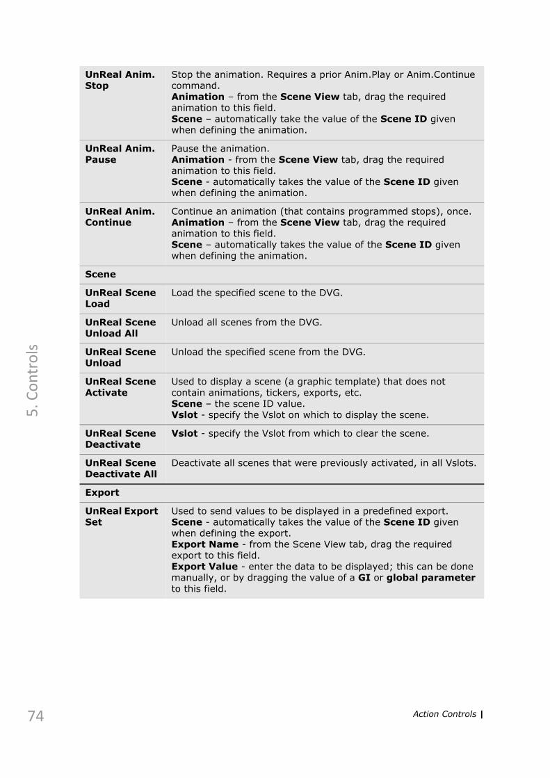
74
5. C
on
tro
ls
UnReal Anim. Stop
Stop the animation. Requires a prior Anim.Play or Anim.Continue command.Animation – from the Scene View tab, drag the required animation to this field. Scene – automatically take the value of the Scene ID given when defining the animation.
UnReal Anim. Pause
Pause the animation.Animation - from the Scene View tab, drag the required animation to this field.Scene - automatically takes the value of the Scene ID given when defining the animation.
UnReal Anim. Continue
Continue an animation (that contains programmed stops), once.Animation – from the Scene View tab, drag the required animation to this field. Scene – automatically takes the value of the Scene ID given when defining the animation.
Scene
UnReal Scene Load
Load the specified scene to the DVG.
UnReal Scene Unload All
Unload all scenes from the DVG.
UnReal Scene Unload
Unload the specified scene from the DVG.
UnReal Scene Activate
Used to display a scene (a graphic template) that does not contain animations, tickers, exports, etc.Scene – the scene ID value.Vslot - specify the Vslot on which to display the scene.
UnReal Scene Deactivate
Vslot - specify the Vslot from which to clear the scene.
UnReal Scene Deactivate All
Deactivate all scenes that were previously activated, in all Vslots.
Export
UnReal Export Set
Used to send values to be displayed in a predefined export.Scene - automatically takes the value of the Scene ID given when defining the export.Export Name - from the Scene View tab, drag the required export to this field.Export Value - enter the data to be displayed; this can be done manually, or by dragging the value of a GI or global parameter to this field.
Action Controls |

5. C
on
trols
UnReal Export SetArray
Used to send values to be displayed in a predefined array export.Scene - automatically takes the value of the Scene ID given when defining the export.Export Name - from the Scene View tab, drag the required array export to this field.Export Values - enter the data to be displayed; this can be done manually, or by dragging the value of a GI or global parameter to this field.Data Delim. - user-defined delimiter that separates values in Export Values field.
GPIO commands
Set Output Set the state for one GPIO channel as required.Index – the number of the GPIO channel (1-16).State – specify True (for ON) or False (for OFF).
Set All Outputs
Set the state for all GPIO channels as required.
Action Controls | 75

76
5. C
on
tro
ls
Graphic Control Commands
For information on the Harris G7 graphic control commands, contact Avid support.
Automation Mediator commands
Send Send a Cue, Play, Stop, or Audio switch preset command to a defined automation system or Automation Mediator control.
CLIP SERVER commands
Cue Clip Cue a clip.isBlocked - select this check box to block the script until the first Cue is finished. Channel - enter the Video Engine channel. ID - set a unique ID to this Cue which can later be used in additional commands, such as Play Clip, Eject Clip or UnCue Clip.Clip - enter the path for the clip.TimeIn - enter the start time of the clip.Duration - enter the duration [in seconds] of the clip to be played.Loop Count - set the number of times the clip is played. You can add a number or select infinite.
NOTE:Only the channel, ID and Clip parameters are required. The remaining values are optional.
UnCue Clip Remove a clip from the cue. Enter the channel of the clip and its ID.
Play Clip Play a clip.Enter the channel of the clip, its ID and the speed at which the clip is to be played.
Eject Unload the playing clip.
Abort Unload all clips on the selected channel.
Set Speed Set speed of an entire channel. Enter the channel number and the speed in a percentage value.
Router control commands
Crosspoint Connect
Set source and destination for an existing router device.
Action Controls |
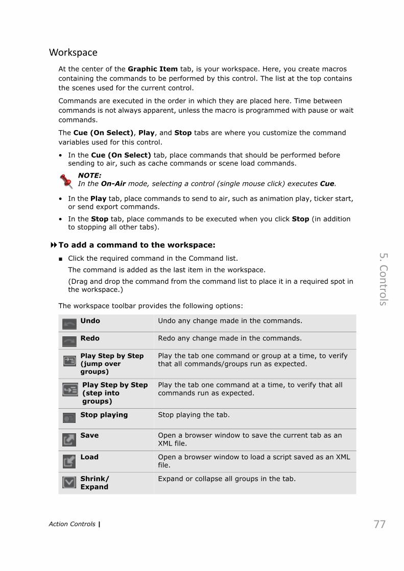
5. C
on
trols
Workspace
At the center of the Graphic Item tab, is your workspace. Here, you create macros containing the commands to be performed by this control. The list at the top contains the scenes used for the current control.
Commands are executed in the order in which they are placed here. Time between commands is not always apparent, unless the macro is programmed with pause or wait commands.
The Cue (On Select), Play, and Stop tabs are where you customize the command variables used for this control.
• In the Cue (On Select) tab, place commands that should be performed before sending to air, such as cache commands or scene load commands.
NOTE:In the On-Air mode, selecting a control (single mouse click) executes Cue.
• In the Play tab, place commands to send to air, such as animation play, ticker start, or send export commands.
• In the Stop tab, place commands to be executed when you click Stop (in addition to stopping all other tabs).
To add a command to the workspace:
■ Click the required command in the Command list.
The command is added as the last item in the workspace.
(Drag and drop the command from the command list to place it in a required spot in the workspace.)
The workspace toolbar provides the following options:
Undo Undo any change made in the commands.
Redo Redo any change made in the commands.
Play Step by Step (jump over groups)
Play the tab one command or group at a time, to verify that all commands/groups run as expected.
Play Step by Step (step into groups)
Play the tab one command at a time, to verify that all commands run as expected.
Stop playing Stop playing the tab.
Save Open a browser window to save the current tab as an XML file.
Load Open a browser window to load a script saved as an XML file.
Shrink/Expand
Expand or collapse all groups in the tab.
Action Controls | 77

78
5. C
on
tro
ls
Additionally, you can remove or disable/enable individual commands for debugging from the right-click menu displayed for each command.
The Cue&Play Toolbar
The Cue&Play toolbar, at the bottom of the workspace, allows you to calculate the time needed for cueing and playing the current control (without regard for the duration of referred scenes, inputs, etc.).
To calculate control times:
■ After all required commands have been added to the workspace, click Cue, Cue&Play, or Play, to calculate the relevant timing for this control.
Scene View
In the Scene View tab, at the right side of the Editor, choose the Renderer type (Unreal Engine or Render Engine). Select the required project and scene, as programmed in Maestro | Designer. From here, select scene elements (animations,
Toggle full screen Toggle the size of the workspace.
Action Controls |

5. C
on
trols
exports, or tickers) to add to a production, and if required, assign a different graphics source.
NOTE:In the Animation tab, you can preview the animation. In the Export tab, you can update the export value.
To add scene elements to commands:
1. Select an output device from the Render list.2. Select the Maestro | Designer project folder from the Projects list.
3. Select the required scene from the Scenes list, and click Load.
The animations, exports, and tickers defined in the scene are displayed below.
4. Drag any element to its respective parameter in a command.
When you first drag a scene element into a command, a dialog box is displayed; subsequent scene elements (from the same scene) use this ID, as well.
To remove a command from the macro:
■ Right-click the command, and then click Remove.
Action Controls | 79

80
5. C
on
tro
ls
GI Parameters
Graphic Item (GI) parameters, on the right side of the Graphic Item tab, connect to a database for data retrieval, and are defined per control.
To create a GI Parameter:
1. In the Graphic Item tab, open the GI Parameters list.
2. Click Add.
The GI Parameter Editor opens.
3. Enter a Name for the parameter.
The name should reflect the data you intend to place in the GI parameter.
Action Controls |

5. C
on
trols
4. Select a type for the parameter, as follows; the type sets the way data can be entered in the GI parameter in the Inputs panel (available from the Sidebar).
5. Select or clear the following options, as required:
6. Click OK.
The GI parameter is created and displayed in the list. It can be duplicated (with a different name) using Duplicate in the right-click menu.
The Query Filter parameters display the GI Parameter’s data (when assigned to a data source), and allow you to edit the data manually.
Set the Live Mode Connections to automatically send GI parameter values to RenderEngine without cueing or playing the control.
To further define the GI parameter, see Actions – The Data Tab on page 83.
Text For free text entries.
Drop-down To display a drop-down list containing defined options.
Browse To open a browser or MediaCentral | Cloud UX window that allows you to browse to a file.
Numeric For numeric (only) entries.
Check Box To display a check box for enabling true/false parameters.
Time To display time in one of the following formats: Timecode, milliseconds, frames.
Conversion Table
Define a basic if-then condition to convert units of time.
Multistyle Text
To open a text editor that allows you to format the text as required.
Slider To display a slider for setting a limited value.
External Parameter
Select this check box to allow a GI Parameter to receive data from an external source (such as an automation system or manual input) or clear the check box to receive data from the GI parameter’s native control only.
Show in Inputs window
Select if you want this GI Parameter to be displayed in the Inputs panel (available from the Sidebar. This can be set in the GI Parameters tab also.
Validation Select the data type that will be validated for playlist events. For more information, see Playlist Validation on page 140.None - GI Parameter is not validated.Text - input must be a text string.Path - input must be an existing path and file name.Numeric - input must be a numeric value.Boolean - input must be a 0 or 1 value (or check box).
Default value
Set a default value for the parameter that can be called by using Set Defaults in the Playout Control.
Action Controls | 81
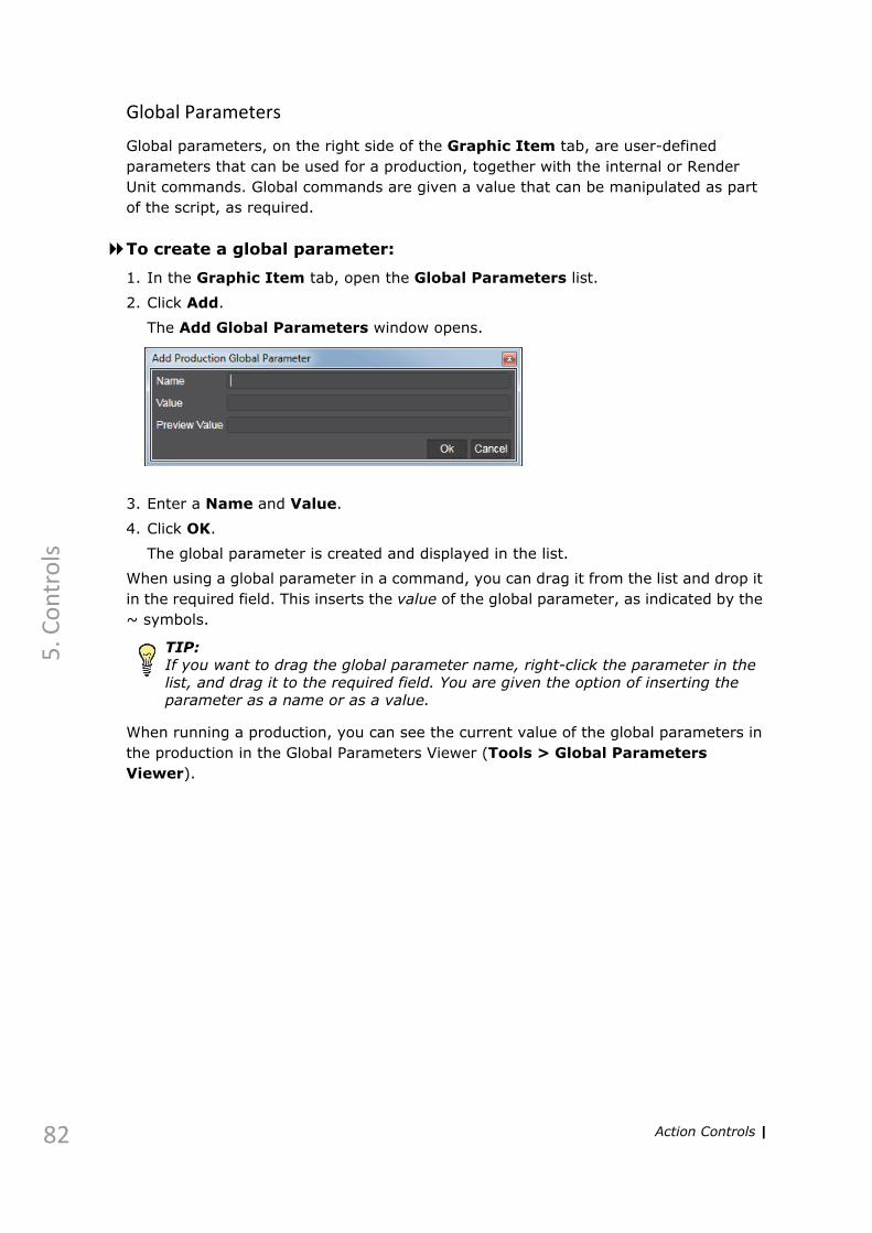
82
5. C
on
tro
ls
Global Parameters
Global parameters, on the right side of the Graphic Item tab, are user-defined parameters that can be used for a production, together with the internal or Render Unit commands. Global commands are given a value that can be manipulated as part of the script, as required.
To create a global parameter:
1. In the Graphic Item tab, open the Global Parameters list.
2. Click Add.
The Add Global Parameters window opens.
3. Enter a Name and Value.
4. Click OK.
The global parameter is created and displayed in the list.
When using a global parameter in a command, you can drag it from the list and drop it in the required field. This inserts the value of the global parameter, as indicated by the ~ symbols.
TIP:If you want to drag the global parameter name, right-click the parameter in the list, and drag it to the required field. You are given the option of inserting the parameter as a name or as a value.
When running a production, you can see the current value of the global parameters in the production in the Global Parameters Viewer (Tools > Global Parameters Viewer).
Action Controls |

5. C
on
trols
Actions – The Data Tab
In the Data tab, set up one or more queries to retrieve data from a database for a GI Parameter. Available GI parameters are listed on the left.
To set up a query:
1. Select the Use Query check box.
The query parameters are enabled. Use the current query or click Add Query to create a new query.
2. Fill in the following parameters, as required.
Execute Query on Cue
Select to execute the query each time the action is cued.
Source drop-down list
Choose a database from the list. The available options are the database connections that you set up in the Data Manager.Click Data Manager to configure your connections. (See Data Source Manager on page 33)
Query field Enter a query using the appropriate query syntax for the selected database. Click Execute to run the query.
Key list Set a key to filter query results, by column.When you use ? in the query syntax, you must define a filtering key to limit the value or set a global or GI parameter to be used in place of ?. Click Add Key (+), and define key name and value. Use the Preprocess check box to replace the query entirely with this key.(In your query, the first key replaces the first ?, the second key replaces the second ?, etc.)If you have not used ? in the query syntax, it is not necessary to define a key.A key can be edited manually from a Data Group.
Action Controls | 83

84
5. C
on
tro
ls
Once you click Execute Query, the query results are displayed beneath the query parameters. If the query syntax is incorrect, the error is shown at the lower part of the query result box and in the server console window.
3. Select one of the following options:
• From the query results, select the cell that you want displayed as the GI parameter value, and drag it to the Query column at the left. The GI parameter will always display the results of this cell, regardless of its contents.
• From the query results, select the column head whose results you want to display as a list in the Inputs list. If you choose this option, you must set the GI parameter type to drop-down list. Query is executed once you press Cue in the playout control.
To refine query results:
1. Double-click the required GI parameter in the Data tab.
The GI Parameter Editor opens with the Query Filter fields enabled.
2. Fill in the following fields as required:
Column The column whose content to display.
Action Controls |

5. C
on
trols
3. Click OK.
Filter Expression
Refine query results here by adding a limiting expression, for example “ID>4”.
Sort Sort query results here by adding an ordering expression, for example, “Name ASC”.
Ordinal The row number of the content to display. This is used together with the column name to specify a permanent cell.
Action Controls | 85

86
5. C
on
tro
ls
Pacer Controls
Pacer controls are used to control tickers, loop animations, and for repetition of macros in general.
To edit a Pacer:
■ Right-click the action control, and select Edit.The Pacer Editor window opens with the Details tab displayed.
To edit the Pacer Details, see Actions – The Details Tab on page 62.
Pacers – The Graphic Item Tab
This section describes the differences between the Graphic Item tab for an Action control, as described in Actions – The Graphic Item Tab on page 66, and the Graphic Item tab for a Pacer control.
Line Manager
The Line manager in a Pacer control allows you to specify the following:
Loops Set the number of time to repeat a complete play of an animation or a ticker. (0=infinite loop).
Delay Choose this option to set a delay between each loop, in hours, minutes, seconds, and milliseconds.
Pacer Controls |
5. C
on
trols
Pacers – Data Tab
See Actions – The Data Tab on page 83
Follow steps 1–2 to set up a query.
Ticker Choose this option to use an available ticker object.Scene – automatically takes the value of the Scene ID given when defining the ticker.Ticker Name – from the Scene View tab, drag the required ticker to this field.Speed - define the speed at which the ticker moves through thevisible area.Offset - set the offset between ticker items.Callback Time - set the delay of the ticker status report.
Pacer Controls | 87
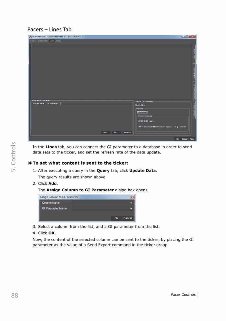
88
5. C
on
tro
ls
Pacers – Lines Tab
In the Lines tab, you can connect the GI parameter to a database in order to send data sets to the ticker, and set the refresh rate of the data update.
To set what content is sent to the ticker:
1. After executing a query in the Query tab, click Update Data.
The query results are shown above.
2. Click Add.
The Assign Column to GI Parameter dialog box opens.
3. Select a column from the list, and a GI parameter from the list.
4. Click OK.
Now, the content of the selected column can be sent to the ticker, by placing the GI parameter as the value of a Send Export command in the ticker group.
Pacer Controls |

5. C
on
trols
Data Groups
A Data Group control displays sets of data from a database, and allows you to choose a set of data and to send its value to a control to be displayed when playing the control.
You can change the layout of the displayed data by clicking on the button from the
data group control’s toolbar:
Table
List
Tiles
Icons
Data Groups | 89

90
5. C
on
tro
ls
Filtering a Data Group
The content of the Data Group can be easily filtered to find the desired value quickly and execute a command as specified in the “On Selection” section.
To setup filtering of a data group:
1. Select Edit from the control’s toolbar.
The Data Editor window opens.
2. In the Hotkeys section, select the Bound column whose values will be used during filtering. Select the “Is case sensitive” option if the search is to be case-sensitive.
3. Specify the actions to be carried out upon the 1st or further selection of the filtered value, as described in On selection (1st, 2nd ...n): on page 93.
4. Click Apply and OK.5. In the Filter text box, type in a text string to search for.
6. To select a single value from the results and execute the commands specified in the “On Selection” section (assign the selected values of the column to named global parameters), type in the next, distinguishing letter of the searched word. You can also click on the desired value to carry out the “On selection” actions.
Data Groups |

5. C
on
trols
When there is only one result, type in the whole word or press enter after the searched value has been found.
TIP:You can add a Select Hotkey to the Data Group. Once this Hotkey is applied, the Data Group becomes active and the cursor is automatically set in the Filter text box.
Editing a Data Group
To edit a Data group:
1. Select Edit from the control’s toolbar.
The Data Editor window opens.
2. Under DataGroup Details, name the control, and assign a unique ID, as described below:
3. Under Query, set up a database query as follows.
NOTE:Queries can be defined for any database defined in the Data Manager (see Data Source Manager on page 33). The database must be connected.
Name The name that is displayed on the Data Group control.To use an identical action name and UID, click the Link icon before entering the action name.
UID A unique identifier that Maestro | Live uses for this control only. If the UID is not linked to the action name, and you leave this field empty, the system assigns a UID automatically.
NOTE:UIDs are the label by which a Maestro | Live device/control is identified to all other devices and controls. It is recommended not to change a UID once it has been set.
Exclude from production
Allows you to save the control independently of the production, in the specified directory. When selected, you can set the name by which to save the control.For more information, see Saving Your Work on page 26.
Source drop-down list
Choose a database from the list. The available options are the database connections that you set up in the Data Manager.
Query field
Enter a query in the query language used by the selected database. Click Execute to run and test the query.
Data Groups | 91
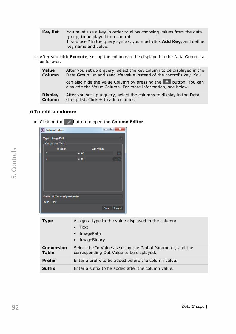
92
5. C
on
tro
ls
4. After you click Execute, set up the columns to be displayed in the Data Group list, as follows:
To edit a column:
■ Click on the button to open the Column Editor.
Key list You must use a key in order to allow choosing values from the data group, to be played to a control.If you use ? in the query syntax, you must click Add Key, and define key name and value.
Value Column
After you set up a query, select the key column to be displayed in the Data Group list and send it's value instead of the control's key. You
can also hide the Value Column by pressing the button. You can also edit the Value Column. For more information, see below.
Display Column
After you set up a query, select the columns to display in the Data Group list. Click + to add columns.
Type Assign a type to the value displayed in the column:• Text• ImagePath• ImageBinary
Conversion Table
Select the In Value as set by the Global Parameter, and the corresponding Out Value to be displayed.
Prefix Enter a prefix to be added before the column value.
Suffix Enter a suffix to be added after the column value.
Data Groups |

5. C
on
trols
5. On selection (1st, 2nd ...n):
6. Click OK.
The Editor is closed and the Data Group list is populated.
Set value to global
Select the global parameter to be assigned the Value after the click.
To add more global parameters, click on .
To remove a global parameter, click on .
Value Select the value column.
On TargetUID
Enter the UID of the target control.
Execute command
Choose which command should be executed on the target control: CtrlCue or CtrlPlay.
Hotkeys Choose the column to be used for filtering. Select whether the search is to be case-sensitive.
Data Groups | 93

94
5. C
on
tro
ls
GPIO Controls
A GPIO control allows you to set a GPIO device to activate Maestro | Live controls (such as Action or Pacer controls), as required.
To edit a GPIO control:
1. Select Edit from the control toolbar.
The GPIO Control Editor opens.
2. Name the control, and assign a GPIO device.
To set up a GPIO device, see GPIO Manager on page 38.
3. Click OK to close the Editor.
4. Click the numbered button for which you want to set a control.
5. Press ALT and drag the control to the required column.
The State On column contains controls that are played when the selected button is pressed.
The State Off column contains controls that are played when the selected button is released.
6. Repeat steps 4–5 for as many GPIO device buttons as required.
To verify that the control is working as required, see Simulating a GPIO Device on page 40.
Playlist Controls
A playlist control is used for creating and running a sequence of controls, both manually and automatically.
For information on playlists, see Playlists on page 122.
GPIO Controls |

5. C
on
trols
Automation Mediator Controls
Automation Mediator controls are used for playing productions from an automation system. Automation Mediator controls cannot be played directly in the Maestro | Live client, however, in order for an automation system to be able to play a production, the production must contain an Automation Mediator control (that is assigned to an Automation Mediator device), that should be assigned to all required Automation systems.
To edit an Automation Mediator:
■ Right-click the Automation Mediator control, and select Edit.The Automation Mediator Control Editor window opens.
The Automation Mediator Control Editor settings are similar to those described for an Action control, and are set the same way.
For more information, see Actions – The Details Tab on page 62.
Automation Mediator Controls | 95
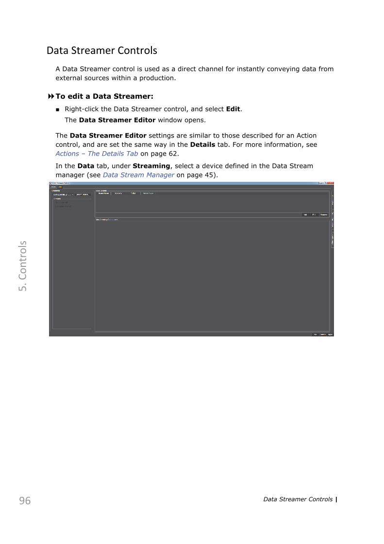
96
5. C
on
tro
ls
Data Streamer Controls
A Data Streamer control is used as a direct channel for instantly conveying data from external sources within a production.
To edit a Data Streamer:
■ Right-click the Data Streamer control, and select Edit.The Data Streamer Editor window opens.
The Data Streamer Editor settings are similar to those described for an Action control, and are set the same way in the Details tab. For more information, see Actions – The Details Tab on page 62.
In the Data tab, under Streaming, select a device defined in the Data Stream manager (see Data Stream Manager on page 45).
Data Streamer Controls |

5. C
on
trols
Clip Viewer Controls
A Clip Viewer control list the clips stored on a defined server for use in the production.
To add a Clip Viewer control:
■ From the Controls menu, select Clip Viewer.A Clip Viewer control is added.
To connect the Clip Viewer control to a Clip Viewer device:
1. In the Clip Viewer control, click Edit .
The Clip Viewer editor is displayed.
Clip Viewer Controls | 97

98
5. C
on
tro
ls
2. Assign a Name and UID, and select a device under Clip Server.To configure a Clip Viewer device, see Clip Server Manager on page 48.
3. Search for clips by creation dates or by adding metadata field to Selected Columns (on the left).
Click OK to close the editor.
To play clips directly from the Clip Viewer:
1. Once you have connected a Clip Server device to the Clip Viewer control, you can play the listed clips on the clip server device using the Player options.
NOTE:The Player options need to be enabled for each Clip Server device. For more information, see Show Player on page 50.
2. You can cue, play, pause and stop the clip. You can also jump to a specific point of the clip using the slider.
3. Information about the current status of the played clip is displayed below the Player options:
To play clips not registered in the Video Engine device:
1. Open the editing options of the selected Clip Server device by going to the Clip Server Manager.
2. In the Browse folder field, enter the path to the clips folder that you want to add to the Clip Viewer control. The folder needs to be shared and accessible by everyone. It also needs to be mounted on the Video Engine Linux machine.
3. In the Clip Viewer, a new option to browse for files appears:
Click on the ... button to open a file browser:
Clip Viewer Controls |

5. C
on
trols
Double-click on the selected clip. The clip is automatically cued in the Clip Viewer.
Clip Viewer Controls | 99

100
5. C
on
tro
ls
ShotBox Controls
You can define the commands to be executed by each LCD key on theShotBox controller to streamline the workflow. The Bank buttons beneath the Touch screen allow you to switch between nine sets (“banks”) of LCD key definitions. Each bank corresponds to a bank button on the controller box.
To add a ShotBox control:
■ From the Controls menu, select ShotBox.
A ShotBox control is added.
To customize the ShotBox LCD keys:
1. Assign the Cue, Play and Stop buttons. Right-click on a bank button and select the appropriate action. To remove an action, select Clear.
2. Three types of playable controls can be added to the ShotBox buttons: Action, Pacer and Playlist. To assign a control to a ShotBox key, add it to the Panel, and then holding the ALT key, drag it to the chosen button.
The key displays the information about the playable action that is going to be executed once the key is clicked on:
The gray status bar and the cue icon indicate that the control is going to be cued upon selection.
ShotBox Controls |

5. C
on
trols
To remove the control, right-click on the button and select Clear. 3. If the ShotBox control is connected to a ShotBox device, then the buttons on the
device are automatically updated with their new controls.
To connect the ShotBox control to a ShotBox device:
1. In the ShotBox control, click Edit .
The ShotBox editor is displayed.
2. Assign a Name and UID, and select a device under ShotBox.
To configure a ShotBox device, see Router Control Manager on page 54.
3. Click OK to close the editor.
The green status bar and the play icon indicate that the control is currently cued and it is going to be played upon selection.
The red status bar and the stop icon indicate that the control is currently played and it is going to be stopped upon selection.
ShotBox Controls | 101

102
5. C
on
tro
ls
4. The ShotBox device buttons are configured as set in the ShotBox control.
ShotBox Controls |

5. C
on
trols
Control Tools
The following controls have toolbars with options for editing the control:
• Data Group
• GPIO
• Playlist (basic)
• Clip Viewer
The following options are available in one or more controls:
Edit Open the Control editor for additional editing and search options.
Delete Delete selected media from the device.
Font Size Set the font size for the clip name display.
Search Type a string to search for. May appear with an expand control to show further search criteria.
Refresh Refresh the display of the items in the control.
In the Clip Viewer, this displays the total play time for all selected clips.
Set Hotkeys Open the Hotkeys dialog box, to set hotkeys (keyboard shortcuts) for the control.For more information, see Hotkeys on page 164.
Save As Open a browser window to save this control as a standalone control, available in all productions.
Load Open a browser window to load a control, previously saved as a standalone control.
Control Tools | 103

6. Widgets
This chapter describes how to set up a widget in Maestro | Live in the following sections:
Widgets on page 105
Widget Properties on page 106

6. W
idgets
Widgets
The following Widgets are available from the Widget Box:
Widgets can be assigned values using the Properties panel or directly in an Action control via a GI Parameter. For more information, see GI Parameters on page 80.
Input Widgets
Textbox Add a Textbox widget to the panel.For more information, see Textbox Properties on page 106.
Label Add a Label widget to the panel.For more information, see Label Properties on page 106.
Combobox Add a Combobox widget to the panel.For more information, see Combobox Properties on page 107.
Check Box Add a Check Box widget to the panel.For more information, see Check Box on page 108.
Spin Box Add a Spin Box widget to the panel.For more information, see Spinbox on page 108.
File Selection Add a File Selection widget to the panel.For more information, see File Selection on page 109.
Slider Add a Slider widget to the panel.For more information, see Slider on page 109.
Conversion Table
Add a Conversion Table widget to the panel.For more information, see Conversion Table on page 110.
Time Add a Time widget to the panel.For more information, see Time on page 111.
Container
Tabwidget Add a Tabwidget to the panel.For more information, see Containers: Tabwidget and Group on page 25.
Group Add a Group widget to the panel.For more information, see Containers: Tabwidget and Group on page 25.
Misc
Image Add an Image to the panel.For more information, see Image on page 111.
Widgets | 105

106
6. W
idge
ts
Widget Properties
Textbox Properties
To display and edit Textbox properties, select the element in the panel and click on the Properties button in the Sidebar. Text displayed in the textbox can be modified in the Edit and On-Air modes.
The following properties can be set for a Textbox element.
Label Properties
To display and edit Label properties, select the element in the panel and click on the Properties button in the Sidebar. A Label can only be modified in the Edit mode. To change the displayed text, double-click on the label.
The following properties can be set for a Label element.
General
Name - set a name for the textbox widget.
Size - set the size of the textbox widget.
Text
FontFamily - select the font family for the displayed text.
FontSize - set the font size for the displayed text.
Align - set the alignment of the text in the textbox.
FontColor - set the font color.
Global Parameters
Parameter - select a Global Parameter to assign the value of the textbox.
Value - set the current text that is displayed in the textbox.
Max Length - set the maximum length of the text displayed in the textbox.
General
Name - set a name for the label widget.
Size - set the size of the label widget.
Text
FontFamily - select the font family for the displayed text.
FontSize - set the font size for the displayed text.
Align - set the alignment of the text in the label.
FontColor - set the font color.
Widget Properties |

6. W
idgets
Combobox Properties
To display and edit Combobox properties, select the element in the panel and click on the Properties button in the Sidebar.
The following properties can be set for a Combobox element.
Global Parameters
Parameter - select a Global Parameter to assign the value of the label.
Value - set the current text that is displayed in the label.
Max Length - set the maximum length of the text displayed in the label.
General
Name - set a name for the combobox widget.
Size - set the size of the combobox widget.
Text
FontFamily - select the font family for the displayed text.
FontSize - set the font size for the displayed text.
Align - set the alignment of the text in the label.
FontColor - set the font color.
Global Parameters
Parameter - select a Global Parameter to assign the value of the label.
Value - set the current text that is displayed in the label.
Items - add the items to be displayed as a drop-down list.
Widget Properties | 107

108
6. W
idge
ts
Check Box
To display and edit Check Box properties, select the element in the panel and click on the Properties button in the Sidebar.
The following properties can be set for a Check Box element.
Spinbox
To display and edit Spinbox properties, select the element in the panel and click on the Properties button in the Sidebar.
The following properties can be set for a Spinbox element.
General
Name - set a name for the check box widget.
Size - set the size of the check box widget.
Text position - set the position of the text (left to right or right to left).
Text
FontFamily - select the font family for the displayed text.
FontSize - set the font size for the displayed text.
FontColor - set the font color.
Text - enter the text to be displayed in the check box.
Global Parameters
Parameter - select a Global Parameter to assign the value of the check box.
Value - set the current value for the check box (set 0 for an unchecked box, or 1 for a checked box).
General
Name - set a name for the spinbox widget.
Size - set the size of the spinbox widget.
Text
FontFamily - select the font family for the displayed text.
FontSize - set the font size for the displayed text.
FontColor - set the font color.
Align - set the alignment of the text in the spinbox.
Global Parameters
Widget Properties |

6. W
idgets
File Selection
To display and edit File Selection properties, select the element in the panel and click on the Properties button in the Sidebar.
The following properties can be set for a File Selection element.
Slider
To display and edit Slider properties, select the element in the panel and click on the Properties button in the Sidebar.
The following properties can be set for a Slider element.
Parameter - select a Global Parameter to assign the value of the spinbox.
Value - set the current value for the spinbox.Min Value - set the minimum value.Max Value - set the maximum value.Step - set the value of a single step. Using the arrows, the spinbox's value will be incremented/decremented by that amount. Precision - set the number of digits after the decimal point.
General
Name - set a name for the file selection widget.
Size - set the size of the file selection widget.
Text
FontFamily - select the font family for the displayed text.
FontSize - set the font size for the displayed text.
Align - set the alignment of the text in the file selection widget.
FontColor - set the font color.
Global Parameters
Parameter - select a Global Parameter to assign the value of the file selection widget.
Value - set the current value for the file selection widget.
Extension - limit the number of displayed files to the chosen extensions (for example png;*xlsx). Extensions must be separated with “;*”
General
Name - set a name for the slider widget.
Size - set the size of the slider widget.
Text
Widget Properties | 109

110
6. W
idge
ts
Conversion Table
To display and edit Conversion Table properties, select the element in the panel and click on the Properties button in the Sidebar.
The following properties can be set for a Conversion Table element.
FontFamily - select the font family for the displayed text.
FontSize - set the font size for the displayed text.
FontColor - set the font color.
Global Parameters
Parameter - select a Global Parameter to assign the value of the slider widget.
Value - set the current value for the slider widget.
Min Value - set the minimum value.Max Value - set the maximum value.Step - set the value of a single step. Using the slider, the widget's value will be incremented/decremented by that amount. Precision - set the number of digits after the decimal point.
General
Name - set a name for the conversion table widget.
Size - set the size of the conversion table widget.
Text
FontFamily - select the font family for the displayed text.
FontSize - set the font size for the displayed text.
FontColor - set the font color.
Global Parameters
Parameter - select a Global Parameter to assign the value of the In Value.
In Value - the In Value as set by the Global Parameter.
Out Value - set the corresponding Out Value.
Widget Properties |

6. W
idgets
Time
To display and edit Time widget properties, select the element in the panel and click on the Properties button in the Sidebar.
The following properties can be set for a Time element.
Image
To display and edit Image widget properties, select the element in the panel and click on the Properties button in the Sidebar.
The following properties can be set for an Image element:
General
Name - set a name for the time widget.
Size - set the size of the time widget.
Text
FontFamily - select the font family for the displayed text.
FontSize - set the font size for the displayed text.
Align - set the alignment of the text in the time widget.
FontColor - set the font color.
Global Parameters
Parameter - select a Global Parameter to assign the value of the time widget.
Value - set the current value for the time widget.
Time format- select the time format: Timecode, Frame, Miliseconds.
General
Name - set a name for the image widget.
Size - set the size of the image widget.
Border visibility - set whether the border of the image should be visible.
Global Parameters
Parameter - select a Global Parameter to assign the value of the image widget.
Image- enter the image path or browse for the chosen image.
Widget Properties | 111

7. Productions
This chapter describes various steps you might take to create a production in Maestro | Live, once you have set up all required devices for your production. The following sections are included:
Creating a Production on page 113
Using If-Then Commands on page 113
Playing Animations on page 115
Running Tickers on page 116
Playing Scenes on page 117
Playing Other Controls on page 118

7. P
rod
uctio
ns
Creating a Production
Before you begin creating a production in Maestro | Live, it is important to review the graphics prepared in Maestro | Designer, and to verify that all graphic elements and exports required for your production are clearly and correctly set up.
When you first open the Maestro | Live client GUI, it opens with an empty production panel, ready for work. You can begin work immediately, or save the empty production to give it a name (see Saving Your Work on page 26).
Set up controls for running all required graphic elements, as described in Controls on page 59.
Using If-Then Commands
If-then commands are a powerful tool for limiting and displaying graphics. For example:
• Limit graphics for specific times of day
• Display graphics only if other graphics have been aired
If-then commands are used together with global and GI parameters, to play controls only when certain conditions are fulfilled, and have the option of defining what to do when the required condition is not fulfilled.
The following procedure is an example of how to create controls to display in-out graphics, when appropriate. For this, you must have in-out animations prepared in Maestro | Designer.
Creating a Production | 113

114
7. P
rod
uct
ion
s
Exam
ple
Using an if-then command to display graphics-in/ graphics-out:1. Create an Action control (see Production Controls on page 60), and name it
“graphics-in”. Assign a device (see Actions – The Details Tab on page 62).
2. In the Graphic Item tab, in the workspace, place an Anim.Play command to define the graphics-in animation (see Anim. Play on page 69).
3. In the Global Parameters list, create a global parameter named “graphics state” with the default value “out” (see Global Parameters on page 82).
4. In the workspace, add a Set Global Parameter command, and set the “graphics state” global parameter value to “in” (see Set Global Parameter on page 68).
This sets the global parameter value to “in” each time the “graphics-in” control is played.
5. Click OK to save the control in the production.
6. Create a new control for “graphics-out” as described in steps 1–2.
7. In the workspace, add a Set Global Parameter command, and set the “graphics state” global parameter value to “out” (see Set Global Parameter on page 68).
This sets the global parameter value to “out” each time the “graphics-out” control is played.
8. Click OK to save the control in the production.
9. Create a third Action control, and name it “in-out”.
10.Add the following If-then command to the workspace:
If a “graphics state” operand =”b“ outThen
Control Play Control UID “graphics-in”
Else
Control Play Control UID “graphics-out”This sets a condition that if the value in the “graphics state” global parameter is “out”, then play the “graphics-in” control. Otherwise, play the “graphics-out” control.
11.Click OK to save the “in-out” control in the production.
Now, when the “in-out” control is played, it plays the “graphics-in” or “graphics-out” controls, with respect to the current value of the “graphics state” global parameter. You cannot play the graphics-out animation if the graphics-in animation wasn’t played previously.
To make the control even more foolproof, you can add a Wait command (see Wait on page 68) between the Anim.Play and Set Global Parameter commands, setting the length of each animation. This ensures that you are not able to play the next control until the current control plays out.
Using If-Then Commands |

7. P
rod
uctio
ns
Playing Animations
Animations can be run using Action or Pacer controls, depending on the repetition required.
It is important to know how an animation was programmed in Maestro | Designer, before creating a control to run it. Programmed animation elements that affect the way a control should be set up include:
• Keyframe name
• Stops
• Looping
• Automatic rewinds
• Start and end keyframes
Animations are run from a control using any of the animation commands (see Render Engine on page 69).
The following procedure is an example of how to create controls to display in-out graphics. For this, you must have in-out animations prepared in Maestro | Designer.
Exam
ple
Displaying a simple graphics-in/graphics-out animation:1. Create an Action control (see Production Controls on page 60), and name it
“graphics-in”. Assign a render unit device (see Actions – The Details Tab on page 62).
2. In the Graphic Item tab, in the workspace, place an Anim.Play command to define the graphics-in animation (see Anim. Play on page 69).
TIP:If you want to play an animation from a certain frame, use the Anim. Start at Frame command instead (see Anim. Start at Frame on page 69), and
specify the frame to start from.
Now, you must decide if you want to play the In and Out animations from the same control (to always play them one after the other), or if you want separate controls for each animation(to allow playing other controls between the In and Out animations).
For separate controls, create another control named “graphics- out”, as described in steps 1–2.
To run both animations from the same control:
3. Place a Pause or a Wait command in the workspace, as required:
Pause – if you want to play the Out animation manually.
Wait – if you want to define a waiting time, after which the Out animation is played automatically.
Place another Anim.Play command in the workspace, to define the graphics-out animation (see Anim. Play on page 69).
Playing Animations | 115

116
7. P
rod
uct
ion
s
Running Tickers
A Ticker should be run using a Pacer control.
To run a ticker, you must select Ticker in the Line Manager section of the Pacer Editor.
All related commands must be placed within in a Ticker command in the workspace (see Pacer Controls on page 86).
When using a Send Export command, the Type must be Ticker.
Each ticker must be assigned to its own pacer control.
The following procedure is an example of how to create controls to run a ticker that draws content from a database. For this, you must have a ticker prepared in Maestro | Designer, and a database (set up as a device).
Exam
ple
Creating a data-based ticker:1. Create an Action control (see Production Controls on page 60), name it, and
assign a device (see Actions – The Details Tab on page 62).
2. In the Query tab, set up a query (see Pacers – Data Tab on page 87).
3. In the Lines tab, click Update Data.
The query results are shown above.
4. In the Graphic Item tab, in the Line Manager, select Ticker.5. In the Scene list, load the Maestro | Designer scene containing the required
ticker.
6. Drag the ticker from the Scene list to the Ticker Name field.
The Scene/Level/Type dialog box opens.
7. Enter a Scene ID, and a default Vslot. 8. Click OK.
The scene is added to the List of Used Scenes.
9. Place a Ticker container in the workspace (see Pacer Controls on page 86).
10.Inside, place a Send Export command.
11.Drag the ticker text export from the Scene list to the Export field.
12.In the GI Parameters list, create a GI parameter (you can leave the value empty).
13.Drag the GI parameter to the Value field of the Send Export command.
14.Set the Type to Ticker.15.In the Lines tab, click Add.
The Assign Column to GI Parameter dialog box opens.
16.Select a column from the list, and a GI parameter from the list.
17.Click OK.
18.Now, when the Pacer control is played, the content displayed in the ticker is the content of the column you assigned to the GI parameter.
Running Tickers |

7. P
rod
uctio
ns
Playing Scenes
Sometimes you want to display a scene as a graphic template without playing scene elements.
(A scene is a set of graphics created in Maestro | Designer. A scene can contain graphics, textures, clips, animations, tickers, etc.)
Maestro | Live enables playing and clearing scenes from a defined Vslot. A Vslot can only display one scene at a time, including the elements in the scene.
To display a scene:
1. Create an Action control (see Production Controls on page 60), name the scene, and assign a device (see Actions – The Details Tab on page 62).
2. In the Graphic Item tab, in the workspace, place a Scene Activate command (see Scene Activate on page 70).
3. In the Scene list, select the required project and scene.
4. Click Set Defaults.
The Scene/Level/Type dialog box opens.
5. Enter a Scene ID.
6. Enter a default Vslot, if required. The Vslot can be set for each Scene Activate command separately.
7. Click OK.
The scene is added to the List of Used Scenes.
8. Drag the scene name from the List of Used Scenes to Scene Name in the Scene Activate command.
9. Enter the required Vslot number.
10.Click OK to save the control in the production.
Now, when you play the control, the scene is displayed on the specified Vslot.
Clearing a scene is done by clearing its Vslot. You can also clear scene elements.
To clear a scene:
1. In an Action control, in the Action Editor, open the Graphic Item tab.
2. In the workspace, place a Scene Deactivate command.
3. Enter the number of the Vslot to be cleared.
4. Click OK to save the control in the production.
Now, when you play the control, the scene is cleared from the Vslot. To clear all Vslots, use the Scene Deactivate All command.
Playing Scenes | 117

118
7. P
rod
uct
ion
s
Playing Other Controls
To play one control from another control:
1. In the source control, place a Control Play command.
2. Enter the Control UID of the target control.
The target control is played when the source control is played.
Playing Other Controls |

8. Databases
This chapter contains information on using a database. It contains the following sections:
Using a Database on page 120

120
8. D
atab
ases
Using a Database
Using a database is a way of airing content without the need for manual input. This reduces the chance of airing incorrect content. Database queries allow you to display data sets as required.
Before you begin, define a database to work with, as described in Data Source Manager on page 33, and verify that the database is connected.
Query results must be placed in a GI parameter, in order to be accessible to Maestro | Live commands.
■ To set up a GI parameter, see GI Parameters on page 80.
■ To set up a query for a GI parameter, see Actions – The Data Tab on page 83.
Query results, in the form of GI parameters, can be used in many types of macro commands used in Maestro | Live. You can use results to play animations and clips, to display text, to update a ticker, to send an export, etc.
The following procedure is an example of how to use a database to update the content displayed in an export. For this you must have a scene with exports created in Maestro | Designer.
Exam
ple
Displaying database content in an export:1. Create an Action control (see Production Controls on page 60), name it, and
assign a device (see Actions – The Details Tab on page 62).
2. In the Graphic Item tab, in the workspace, place a command to display the graphic set that contains your export.
3. Load the graphics, and click Cue & Play to display the graphics.
4. In the GI parameters list, create a GI parameter and name it appropriately for your export.
5. In the workspace, add a Send Export command.
6. From the Scene list, drag the relevant export to the Export field of the Send Export command.
7. From the GI parameters list, drag the GI parameter you created to the Value field of the Send Export command.
8. In the Data tab, set up and execute your query to assign the required data to the GI Parameter (see Actions – The Data Tab on page 83).
9. Click OK to save the control in the production.
Now, you have a number of possibilities.
• If you selected the content of a cell, you can display the data in the export (Cue & Play).
• If you selected the content of a column, you can select the data set from list in the Inputs list, as follows:
a. In the Production window, select the control, and click Cue.
b. In the Inputs list, from the drop-down list, select the required data set.
c. Click Apply.(cont.)
Using a Database |

8. D
atabases
Exam
ple
d. Click Play.
The data set is displayed in the export.
• If you have a Data Group control, you can select a data set to display from the Data Group.
a. Create a Data Group control and connect it to your database (see Data Groups on page 89).
b. In the Action control, in the Data tab, set up a query and set a key as required.
For example, In an MS Excel database, use the query:
select * from [shows$]where id=?
And set a key named “id” with a default value of 1.
c. Click Execute.
d. Drag the cell that you want to display in the export, to the Query column at the left.
e. Click OK.
f. In the Production window, select the data set that you want to display from the Data Group.
g. Click Cue & Play.
The selected data set is displayed in the export.
Using a Database | 121

9. Playlists
There are two types of playlist controls in Maestro | Live;
• The Advanced playlist is used to create playlists that play all graphics and video feed, with or without a scheduler. This is the preferred playlist type. (Referred to as Advanced Playlist in the Controls menu.)
• The more basic playlist is used for productions that will be controlled from an automation system. This is a legacy playlist type. (Referred to as Playlist in the Controls menu.)
This chapter describes how to set up a playlist, in the following sections:
Advanced Playlist Controls on page 123
Building a Playlist on page 136
Legacy Playlist Controls on page 142

9. P
laylists
Advanced Playlist Controls
An Advanced playlist control allows you to define a sequence in which to play controls during a broadcast (“events”), and set their order, timing, and more.
In order to use a playlist, you must set the time-base appropriate for your studio setup. For information on how to do this, see Server on page 157.
When you add a playlist by right-clicking the production panel, and selecting from the available controls, the Advanced playlist control is added to the production. It is available in the Controls menu, as well.
The following options are available in the Advanced playlist toolbar:
Validate Validate all items in the playlist. For more information, see Playlist Validation on page 140.
Cue Cue the events in the Playlist. To cue a single event, right-click the event and select Cue.
Play Play the events to the defined device. The default playlist work mode for timing events is defined in the playlist settings (see Playlist Work Mode on page 127).To set the timing for individual events, right-click the event, select Event Type, and set the type (as described in Playlist Work Mode on page 127).
Play next
Stop the currently playing event and play the next scheduled event.
Stop Stop the playlist sequence at the end of the currently playing event.
Reset Reset the status of all events and set the first event as the current event.
Edit Mode
Toggle to unlock the playlist control for editing (column header is highlighted in blue) or locked for editing by toggling this button.
Set Clock Right-click set clock to display a list of times that can be displayed in the playlist
Advanced Playlist Controls | 123

124
9. P
layl
ists
Playlist Menu
Events Menu
New Clear the current playlist of events.
Open Open a browser window to load a saved playlist in place of the current playlist.
Insert Open a browser window to insert a saved playlist into the current playlist. New content is added as a group (or groups) after the currently selected group.
Append Open a browser window to append a saved playlist to the end of the current playlist.
Refresh Refresh the displayed events in the playlist.
Save As Open a browser window to save the playlist as a standalone item, available to all productions.
Validate Validate all items in the playlist.For more information, see Playlist Validation on page 140.
Cue Cue the events in the Playlist.
Play Play the events to the defined device. The default playlist triggering type is defined in the playlist settings (see Playlist Work Mode on page 127).
Play Next Stop the currently playing event and play the next scheduled event.
Stop Stop the playlist at the end of the currently playing event.
Reset Reset the status of all events and set the first event as the current event.
Hotkeys Open the Hotkeys dialog box, to set hotkeys (keyboard shortcuts) for various actions.For more information, see Hotkeys on page 164.
Remove Remove this Advanced Playlist control from the production.
Load Event Open a browser window to open an event saved from a different playlist or production.
Save Event Save the selected event as a standalone object.
Edit Event Open the Edit Event dialog box to set UID, type, time, cue timeout, and duration.
Event Type Set the triggering type of the selected event to Auto Advance, Manual, or Clock. For more information, see Playlist Work Mode on page 127.
Cut/Copy/Paste
Cut, copy, or paste the selected event.
Validate Validate the selected event.
Cue Cue the selected event.
Advanced Playlist Controls |

9. P
laylists
Tools Menu
Pause Pause the selected event.
Skip Set the selected event to be skipped in the playlist.
Edit Control
For events that reference controls, open the control editor.
Create Dummy Event
Add a dummy event to the playlist.
Create Group
Add an empty group to the playlist. For more information, see Groups on page 138.
Expand All Expand the display of all events in the current group.
Shrink All Collapse the display of all events in the current group.
Properties Open the Group Properties dialog box to change the group name or Triggering Date. For more information, see Groups on page 138.
Remove Remove the selected event or group from the playlist.
Settings Open the Advanced Playlist Editor to set playlist preferences. For more information, see Advanced Playlist Settings on page 126.
Set Condition...
Open the Playlist Rules Builder to trigger actions when editing the playlist. For more information, see Playlist Rule Builder on page 139.
Advanced Playlist Controls | 125
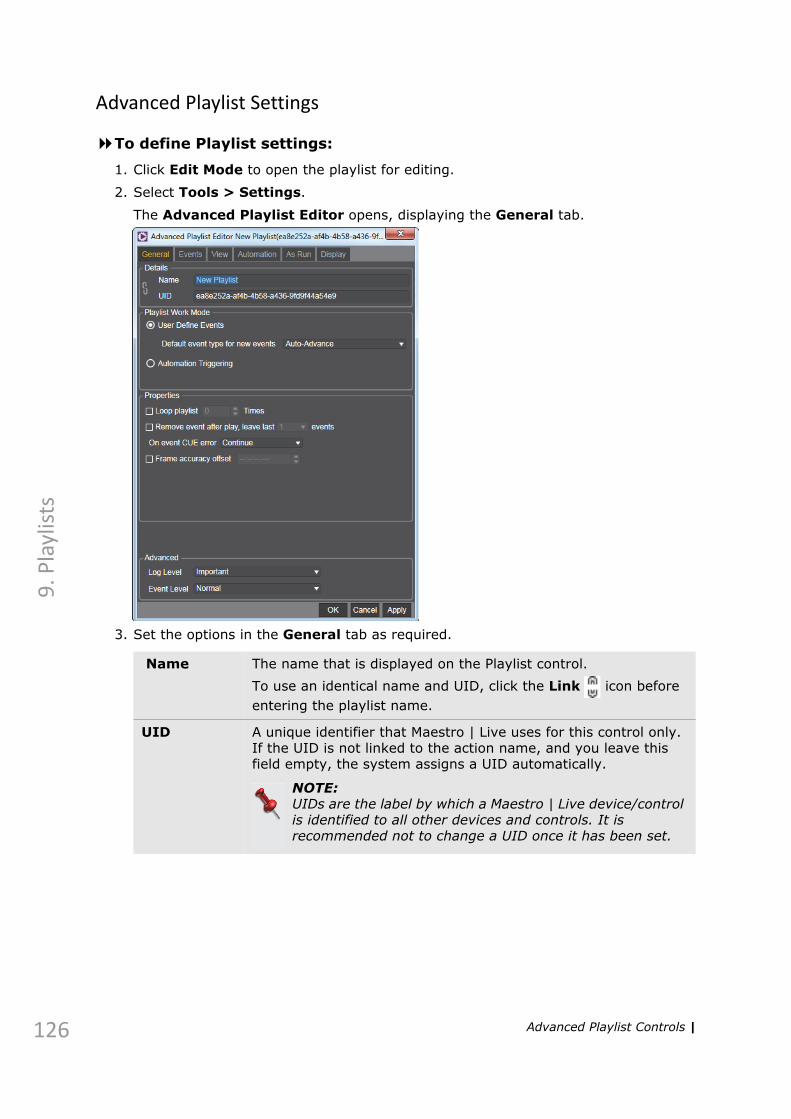
126
9. P
layl
ists
Advanced Playlist Settings
To define Playlist settings:
1. Click Edit Mode to open the playlist for editing.
2. Select Tools > Settings.
The Advanced Playlist Editor opens, displaying the General tab.
3. Set the options in the General tab as required.
Name The name that is displayed on the Playlist control.To use an identical name and UID, click the Link icon before entering the playlist name.
UID A unique identifier that Maestro | Live uses for this control only. If the UID is not linked to the action name, and you leave this field empty, the system assigns a UID automatically.
NOTE:UIDs are the label by which a Maestro | Live device/control is identified to all other devices and controls. It is recommended not to change a UID once it has been set.
Advanced Playlist Controls |

9. P
laylists
Playlist Work Mode
Set if the playlist is run according to the setting defined in the playlist (User Defined Events) or by Automation Triggering. (See step 6 for information about setting automation parameters.)If you select User Defined Events, set Default event type for new events to determine how the playlist is played out. By default, the time assigned to each event (after the first) depends on the duration of the previous event, but you can set time manually, as required. (To set a date for the group, see Groups on page 138.)Auto Advance - play one event after another, according to the order set in the playlist. Clock - play events according to the time set for each event. Manual - each event in the playlist must be played manually.
Loop Playlist
When this check box is selected, the playlist is played out in a loop. You can set the number of loops to play in the Loop Times field (0=infinite).When cleared, the playlist is played once.
Remove Event After Play
When this check box is selected, the playlist is cleared of events that were played, not including the most recent items. You can set the number of the recent items to keep, in the Leave Last X Events field. Remember that if you save the production after events are removed, that is how the playlist is saved.When the check box is cleared, events are left in the playlist.
On event CUE error
Select the action to take if an event is not cued correctly; Continue with next to play the next event, Stop playlist, or Continue to play the current event despite the error.
Frame accuracy offset
Set a delay in order to keep frame accuracy (HH:MM:SS:FF).
Log Level Set up advanced logging options for the control, other than what you set in the Application Settings dialog box.
Event Level
Advanced Playlist Controls | 127

128
9. P
layl
ists
4. Click the Events tab to set the following;
Default Cue Timeout
The default Cue time given to events when they are added to the playlist, provided the time was not calculated in the control (see The Cue&Play Toolbar on page 78) or that the actual cue time, is shorter than the default.
Default Duration Time
The default Duration time given to events when they are added to the playlist, provided that the time was not calculated in the control, or that the actual duration is shorter than the default.
Clone Used Actions
Select this check box to create virtual copies of the controls used in the playlist, to allow using the same control sequentially in different events with different data.I.e., one instance can be playing while another instance (with different data) is being cued.
Send event duration to GI Parameter
When the event is cued, send its duration to the defined GI parameter.
Advanced Playlist Controls |

9. P
laylists
Get event duration from GI Parameter
When creating an event, its duration is set according to the duration specified in the defined GI parameter, provided that the GI parameter duration is greater than the actual duration of the event. If the GI parameter duration is lesser than the actual event duration, the default event duration is used.
Countdown event duration
When selected, the event duration countdown is displayed in the duration column in the playlist. When cleared, the duration of the clip is displayed.
Forward event duration to control play time
Send event duration to Action control as play time upon cue.
Validate associated controls on event validation
When selected, when validating a playlist event, validate the associated controls (events), as well. When cleared, associated controls (events) are not validated.
Lock playlist event file (.fzn) on CUE
Select to protect playlist event file during cue and play.Fail CUE on playlist events (lock) error - if playlist event file cannot be locked, report cue failure.
When event is stopped
Set what action to take when event is stopped; reset or stop the playlist control.
Expand primary event on CUE
When selected, show the expanded view of an event, when the event is cued.
Advanced Playlist Controls | 129

130
9. P
layl
ists
5. In the View tab, move the fields that you want to display as playlist columns into the Selected Columns.
If you want all subsequent playlists to be displayed this way, click Set as Default.
Event ID The unique identifier assigned to a playlist event. If one control is added to the playlist twice, two events are created, each with it’s own UID.
Time Scheduled event time. (Depends on the event type.)
Device Video engine device name and UID.
SOM Start of Media time for clip.
Control Name & UID
The name and UID of the control to run.Name [UID].
Details Displays the scene ID and Vslot details of the scene(s) used by the referred control (assigned in the Scene View sub-tab) for a graphic event, or the clip path for a clip event.
Key & Value
If the control referred to by the event uses a database query containing a key (allowing you to choose inputs from a data group), the key name is displayed in this column.
Advanced Playlist Controls |

9. P
laylists
Display Data
Displays the data matching the specified query key for the event, defined as a display column in the data group. Up to four columns can be displayed for a key. If the selected key is changed (for the event), the change is sent to the referred control, only after the event is cued.
Input Displays the input value that was specified for the control. Up to four input values can be displayed, regardless of the number of inputs in the Playout Controller.
Cue TimeOut
The time set for cueing the event. Default cue time is set in the Default Cue Timeout field. You can calculate the cue time by clicking Cue in the control editor. (See The Cue&Play Toolbar on page 78).
Play Time The time required to trigger all the commands in the control referred to by the event. You can calculate the play time by clicking Play in the control editor. (See The Cue&Play Toolbar on page 78).
Duration The time for which the event will remain current, before moving on to the next event. The duration can be set differently from the play time, so that you can move to the next event before the current event is played out, or leave the current event on air after it is played out.The default duration is set in the Default Duration Time field.
Status Shows the current status of the event, with color coding. When the status is underlined, you can click it to get assistance from the application.
Advanced Playlist Controls | 131

132
9. P
layl
ists
6. If your selected Playlist Work Mode (see page 127) is Automation Triggering, the parameters in the Automation tab become available. Set the following parameters as required:
Device Select the automation device to be used with this playlist. Devices are set as described in Automation Mediator Manager on page 41.
Path Set the location where playlist events are stored.
Expose storage event UIDs to automation
When selected, the Automation system can read saved storage events. When cleared, saved storage events are not accessible to automation.
On validation, load missing events from storage
When you validate the event in the playlist, load missing events from storage if the event is missing (and UID exists in storage).
Event UID [First Letter] Conversion
When selected, specify the first letter of the UID sent by the automation system to be replaced with the specified letter.
Advanced Playlist Controls |

9. P
laylists
Force event reloading
When selected, upon validation, even if a playlist event is already loaded, it is reloaded from storage. When cleared events are not reloaded.
Expose loaded event UIDs to automation
Allow automation to get information on loaded events.
Enable auto ordering by event status
When this check box is selected, the events in the playlist are automatically (and continually) ordered according to their Status.
Update event duration with received duration
Replace the currently known event duration with the duration parameter sent by the automation system.
On Cue, validate event and cue
When this check box is selected, events are validated and cued when the system receives a Cue command. When cleared events are only cued.
On Validate, respond with status for:
When validating, select what event status is sent to the automation system: Primary or Primary+Secondary.
On Cue, respond with status for:
When cueing, select what event status is sent to the automation system: Primary or Primary+Secondary.
Advanced Playlist Controls | 133

134
9. P
layl
ists
7. You can record all events played from a playlist in a file, each time an event is sent to air. In the As Run tab, set the following options.
Enable ‘As Run’ File
Select this check box to create the As Run log file. When cleared, played events are not logged.
File Browse to select a file to use for logging. Logs are saved per day in the specified location, using the original name with the current date.
Separator Define the character to be used as a separator between columns.
Separator Replacement
Define the alternate character to be used as a separator between columns, if the defined separator is in use.
Advanced Playlist Controls |

9. P
laylists
8. You can set the background coloring and the font of your events, depending on their type. Open the Display tab to set the required options:
9. Click OK when finished, to save your settings.
Enable customized event colors
Select this check box to enable the option for setting different colors of backgrounds and fonts for playlist events.
Brush Select whether the background coloring should be in form of a solid color or gradient.
Background Select the background colors for the different types of events: Graphic, Clip, Other.
Font Select the font colors for the different types of events: Graphic, Clip, Other.
Advanced Playlist Controls | 135

136
9. P
layl
ists
Building a Playlist
After setting up your controls and devices, you can create a playlist to use as a structured sequence to be played in a broadcast.
Events are displayed as rows in the playlist, and their order is the sequence in which the list is played.
Events are added to the playlist as primary events or secondary events. Primary events take their timing from the event group. Secondary events are nested beneath a primary event and take their timing from the primary event.
Router, GPI, and OVS Recorder events can also be linked to a primary event.
To build a playlist:
1. Add a Playlist control to the current production (Controls > Advanced Playlist).
2. Click Edit Mode to enable the Playlist control for editing.
When Edit mode is enabled, the column header is highlighted in blue.
3. Edit the Playlist settings as required (see Advanced Playlist Settings on page 126).
4. Drag any control or clip to the Playlist, using the drag area, and holding down the ALT key.
This creates a playlist event that points to the selected control or clip.
To add a secondary event, drop the control or clip on a primary event in the playlist.
To turn a primary event into a secondary event or vice versa, use ALT and drag.
NOTE:Events can only be placed within a group (see Groups on page 138).
5. Edit the Playlist events as required, by selecting an event (in Edit mode) and using the options available in the Events menu or by right-clicking an event and selecting an option.
For more information, see Events Menu on page 124. Click Validate to validate all events in the playlist.
For more information, see Playlist Validation on page 140.
6. Click Edit Mode to lock editing, and prevent errors during play.
When done, Cue and Play the Playlist to verify that it plays out correctly, and adjust settings if required.
Building a Playlist |

9. P
laylists
Scheduling Individual Events
Playlist events are assigned a scheduling type when you add them to the playlist. The default event type is set in the Playlist Mediator preferences (see Playlist Work Mode on page 127). For primary events, the time displayed in the Time column in the playlist is calculated for each event, according to the duration of the event before it. Secondary events take their start time from their primary event.
The available event types are:
You can change the event type in the playlist as required.
To change the event scheduling type:
■ Right-click the event in the playlist and select Event Type. Select the required type from the list.
NOTE:A yellow triangle indicates that scheduled time has passed.
Tied Events
Tied events are events that execute a device-related behind-the-scenes action; you can define a router, a GPI device or a recorder. Tied events can be tied to primary events only. A primary event with a tied event displays an indicator in the playlist. All devices must be set up to define an event.
To create a tied event:
1. Right-click the required primary event.
2. Select Tied Event and select an event type.
A dialog box is displayed, different for each type of event.
3. Click Add to create an event that can be configured to its specified device.
Auto Advance The event is played automatically after the previous playlist event has played out.
Manual You must play the event manually.
Clock The event is played at the time specified in the playlist.
Router For a router event, select the device and set the source & destination routing.
GPI For a GPI event, select the device and set the channel and state.
Recorder For a recorder event, select the device and set the recording tag, name, and duration.
Building a Playlist | 137

138
9. P
layl
ists
Groups
A group in the playlist is a container for events. Groups can be assigned a name and start time.
To add a group:
■ Right-click the list area in the playlist, and select Create Group.
A new group is added to the playlist.
To set group properties:
1. Right-click on the group, and select Properties.
A dialog box is displayed.
2. Rename the group as required, or set a triggering date.
3. Click OK.
The group is updated with the new parameters.
NOTE:The Triggering Date check box is enabled when the first event in the group is a clock event.
Building a Playlist |

9. P
laylists
Playlist Rule Builder
You can set events to be added automatically to the playlist when:
• Adding an event to the playlist
• Opening a different playlist (using Playlist > Open)
• Inserting a different playlist (using Playlist > Insert)
• Appending a different playlist (using Playlist > Append)
To create a rule:
1. Select Tools > Set Condition... in the Playlist.
2. The Playlist Rule Builder is displayed.Select when the rule/s will be applied.
Building a Playlist | 139

140
9. P
layl
ists
3. Under Rules, type in a Name for the rule and click to expand the rule options.
4. Select Is enabled to activate the rule when defined or clear to disable the rule.
5. Define the rule as follows:
Click to set additional conditions or filters for the rule, and set And or Or as required.
6. Click to set additional parameters for specifying the event to add and set Event ID, Duration, Time Shift, Control UID, and/or Control Data, as required.
7. Add as many rules as required.
8. Click OK to save the rules and close the Playlist Rule Builder.
Playlist Validation
Playlist events can be validated, according to the following parameters:
1. The control referred to by the event is loaded in the production.
2. The output device is connected (if an output device is assigned).
3. The scene is loaded to the output device.
For Select the type of event the rule applies to, Primary or Secondary.
When Content Type
Select the content type the rule applies to Dummy, Graphic or Clip.
Add Event Select the type of event that is added when the above condition occurs, Primary or Secondary.
Content Type Select the content type that is added when the above condition occurs, Dummy, Graphic, GPI, Router, Recorder.
Building a Playlist |

9. P
laylists
4. The required database is connected (if a query is defined for the control).
5. Data matches the validation type set for the GI parameters (see Validation on page 81).
As part of the validation process, a transfer request is sent to the central storage if clip is missing on local storage if this option is enabled in the assigned Clip Server device (see Allow Clip Transfer on page 50).
The validation process is stopped if an item in the list is not validated, and an error message is displayed. Validation can be done manually or from an automation system (using the playlist/event UID).
To validate the playlist:
■ Click to run validation.
To validate a playlist event:
■ Right-click the event and select Validate.
Building a Playlist | 141

142
9. P
layl
ists
Legacy Playlist Controls
The [basic] Playlist control allows you to define a sequence in which to play controls during a broadcast (“events”), and set their order, timing, and more.
This section explains the settings available for a playlist control. For information on building a playlist, see Building an Automation Playlist on page 152.
In order to use a playlist, you must set the timebase appropriate for your studio setup. For information on how to do this, see Server on page 157.
To define Playlist settings:
1. Click Settings .
The Playlist Settings dialog box opens.
Legacy Playlist Controls |

9. P
laylists
2. Set the options as required.
Name The name that is displayed on the Playlist control.To use an identical name and UID, click the Link icon before entering the playlist name.
UID A unique identifier that Maestro | Live uses for this control only. If the UID is not linked to the action name, and you leave this field empty, the system assigns a UID automatically.
NOTE:UIDs are the label by which a Maestro | Live device/control is identified to all other devices and controls. It is recommended not to change a UID once it has been set.
Log Level Set up advanced logging options for the control, other than what you set in the Application Settings dialog box.
Event Level
Auto Advance Mode
Determines how the playlist is played out.When this check box is selected, events are played one after another, according to the timing set in the playlist.When this check box is cleared, events in the playlist must be played manually, by clicking Play (or from an automation system).
Loop Playlist When this check box is selected, the playlist is played out in a loop. You can set the number of loops to play in the Loop Times field (0=infinite).When cleared, the playlist is played once.
Remove Event After Play
When this check box is selected, the playlist is cleared of events that were played, not including the most recent items. You can set the number of the recent items to keep, in the Leave Last X Events field. Remember that if you save the production after events are removed, that is how the playlist is saved.When the check box is cleared, events are left in the playlist.
Default Cue Timeout
The default Cue time given to events when they are added to the playlist, provided the time was not calculated in the control (see The Cue&Play Toolbar on page 78) or that the actual cue time, is shorter than the default.
Default Duration Time
The default Duration time given to events when they are added to the playlist, provided that the time was not calculated in the control, or that the actual duration is shorter than the default.
Clone Used Actions
Select this check box to create virtual copies of the controls used in the playlist, to allow using the same control sequentially in different events with different data.I.e., one instance can be playing while another instance (with different data) is being cued.
Send event duration to GI Parameter
Get the event duration of the currently played event from the automation system and send it to the GI parameter defined here.
Legacy Playlist Controls | 143

144
9. P
layl
ists
Validate associated controls on event validation
When selected, when validating a playlist event, validate the associated controls (events), as well. When cleared, associated controls (events) are not validated.
Forward event duration to control play time
Send event duration to Action control as play time upon cue.
Lock playlist event file (.fzn) on CUE
Select to protect playlist event file during cue and play.Fail CUE on playlist events (lock) error - if playlist event file cannot be locked, report cue failure.
Fail CUE on playlist events (lock) error
If playlist event file cannot be locked, report cue failure.
Legacy Playlist Controls |

9. P
laylists
3. Click the View tab to set the columns to be shown in the playlist.
4. Select the check box next to the columns you want to display, as follows.
If you want all subsequent playlists to be displayed this way, click Set as Default.
Allow event sorting by column
When selected, you can sort the events in the playlist according to the values in each column, by clicking the column header. When cleared columns cannot be sorted.
Event UID The unique identifier assigned to a playlist event. If one control is added to the playlist twice, two events are created, each with it’s own UID.
Legacy Playlist Controls | 145

146
9. P
layl
ists
Type Signifies the timing Maestro | Live applies to an event.P=Primary.S=Secondary (timing that is relative to a primary event).D=Dummy is used when adding an event to the playlist, without dragging a control. This type of event is used to add a time-limited pause to the playlist, so that the entire playlist is paused for the duration of the dummy event.
Delay Defines a delay before the current event is played.If a delay is set, the event is played automatically following the previous event, with the delay applied, regardless of the playlist’s Auto Advance Mode setting (see Auto Advance Mode on page 143).
Control Name & UID
The name and UID of the control to run.Name [UID].
Scene Details
Displays the scene ID and Vslot details of the scene(s) used by the referred control (assigned in the Scene View sub-tab).
Key If the control referred to by the event uses a database query containing a key (allowing you to choose inputs from a data group), the key name is displayed in this column.
Value If the control referred to by the event uses a database query containing a key, the current key value is displayed in this column.
Display Data
Displays the data matching the specified query key for the event, defined as a display column in the data group. Up to four columns can be displayed for a key. If the selected key is changed (for the event), the change is sent to the referred control, only after the event is cued.
Inputs Displays the input value that was specified for the control. Up to four input values can be displayed, regardless of the number of inputs in the Playout Controller.
Cue Time The time set for cueing the event. Default cue time is set in the Default Cue Timeout field. You can calculate the cue time by clicking Cue in the control editor. (See The Cue&Play Toolbar on page 78).
Play Time The time required to trigger all the commands in the control referred to by the event. You can calculate the play time by clicking Play in the control editor. (See The Cue&Play Toolbar on page 78).
Duration The time for which the event will remain current, before moving on to the next event. The duration can be set differently from the play time, so that you can move to the next event before the current event is played out, or leave the current event on air after it is played out.The default duration is set in the Default Duration Time field.
Validation The validation status of the event (failed, succeeded, validating).For more information, see Playlist Validation on page 140.
Status Shows the current status of the event, with color coding. When the status is underlined, you can click it to get assistance from the application.
Legacy Playlist Controls |

9. P
laylists
5. Under Data Display Column, determine the number of attributes (up to four) that are displayed in the Display Data column of the playlist.
Click + to add attributes, and enter characters to use as separators in the left field.
6. Under Inputs, determine the number of GI parameters (up to four) that are displayed in the Inputs column of the playlist.
Click + to add attributes, and enter characters to use as separators in the left field.
7. Under Metadata columns, define additional columns from the metadata fields to display in the playlist, as required.
(These settings are available when using the SQL database storage option.)
For information on editing your playlist, see Building an Automation Playlist on page 152.
Legacy Playlist Controls | 147

148
9. P
layl
ists
Running a Basic Playlist from an Automation System
Unlike other production controls, playlist events do not need to have an Automation Mediator control in the production, in order to be played from a Automation system. An Automation device must be set up, as described in Automation Mediator Manager on page 41, and the automation system runs individual events, with the properties that are set in the playlist. Events are loaded only upon validation.
To allow triggering Playlist events from an Automation system:
1. Click the Settings button.
The Playlist Settings dialog box opens.
2. Open the Automation tab.
3. Set automation settings as described in step 6 of Advanced Playlist Settings.
Legacy Playlist Controls |

9. P
laylists
4. Click OK.
Each Playlist event is triggered by the Automation system, using the event UIDs.
NOTE:In order to play a complete playlist from an automation system, a Automation Mediator control must be defined, and the automation system must send the UID of the playlist.
Legacy Playlist Controls | 149

150
9. P
layl
ists
Logging Playlist Events
You can record all events played from a playlist in a file, each time an event is sent to air.
To log played events:
1. Click the Settings button.
The Playlist Settings dialog box opens.
2. Open the As Run tab.
3. Select the Enable ‘As Run’ File check box.
4. If required, browse to a different file in which to log the events, and set a character to use as a separator.
5. Click OK.
Events are logged to the selected file, when the playlist is played.
Legacy Playlist Controls |

9. P
laylists
Metadata tab
In the Metadata tab, you can fill in metadata for the Playlist control, as required.
NOTE:The Metadata tab is available only when using SQL database storage. For more information, see Storage on page 162.
Legacy Playlist Controls | 151

152
9. P
layl
ists
Building an Automation Playlist
NOTE:You must select a time-base, in order for a playlist to run properly. For more information, see Server on page 157.
The following options are available in the Playlist toolbar:
Settings Opens a dialog box that allows you to set the way the current Playlist control is run, displayed, logged, etc. (See In the View tab, move the fields that you want to display as playlist columns into the Selected Columns. on page 130).
Save As Opens a browser window, allowing you to save the playlist outside of the current production folder (while retaining a link from the production to the playlist).For more information, see Saving Controls on page 28.
Load Opens a browser window, allowing you to load a previously saved playlist in place of the current control.
Hotkeys Open the Hotkeys dialog box, allowing you to set the hotkeys to Select or to Select & Play the current playlist.For more information, see Hotkeys on page 164.
Font Size
Set the font size in which to display playlist events.
Load Missing Controls
Load controls referenced by the playlist, that have not been loaded as part of the production, or are not saved in the same production as the playlist.
Refresh Refresh the playlist by reading its current state from the server.
Remove Remove Playlist control from production.
Search Search within playlist events.
Validate Validate all items in the playlist. For more information, see Playlist Validation on page 140.
Cue Cue the current event in the Playlist.
Play Play the current event to the defined device (and continues playlist if Auto Advance mode is set).
Stop Stop the playlist sequence at the end of the current event.
Legacy Playlist Controls |

9. P
laylists
To build a playlist:
1. Add a Playlist control to the current production (Controls > Playlist).2. Edit the Playlist as required (see Automation Mediator Controls on page 95).
3. Click Edit Mode to enable the Playlist control for editing.
4. Drag any control to the Playlist, using the drag area, and holding down the ALT key.
This creates a playlist event that points to the selected control.
5. Edit the Playlist events as required, by selecting an event (in Edit mode) and using the Edit Event button or the TAB key.
6. Click Edit Mode to lock editing, and prevent errors during play.
When done, Cue and Play the Playlist to verify that it plays out correctly, and adjust settings if required.
Set as Current
Set the selected event to be the current event (the next event to be played).
Reset Reset the status of all events and sets the first event as the current event. You can choose whether to load the playlist from the last saved version (to include removed events), or not (to reset the status of the events currently displayed in the playlist).
Edit Mode
The playlist control can be locked for editing (playlist is highlighted in blue) or open for editing (playlist is highlighted in green), by toggling this button.
Add Event
Add a dummy event to the playlist.
Load Event from Storage
Open the Fusions folder to allow you to open an event saved from a different playlist or production.
Edit Event
Open a dialog box allowing you to edit some of the event properties.
Remove Event
Remove the selected event from the playlist.
Edit Control
Open the editor for the control referenced by the selected event.
Legacy Playlist Controls | 153

154
9. P
layl
ists
Automatic Event Creation
The Playlist creator is used to define rules for manipulating the automation playlist. Define a playlist event to be created when Maestro | Live receives certain commands from the automation system. The new event is added to an existing playlist in the production, defined in the rule.
To create automatic playlist events:
1. In the Tools menu, select Playlist Creator.2. In the Playlist Creator dialog box, click Add New Rule.
The Add Rule Definition dialog box is displayed.
3. Define the following parameters for the rule:
4. Under Rule definition, define the rule as required (file type must be selected in order to define rule logic)
5. Click OK.
The rule is displayed in the Playlist Creator dialog box.
Name Set the name for this rule (used only in the Playlist Creator dialog box).
File type Select the system/file type from the list.In the current version, only the Harris system file type is applicable.
Source file Set the automation system playlist file.
Destination file
Set the Maestro | Live playlist file to which the event will be added.
Startup type Set when to run this rule
Automatic Event Creation |
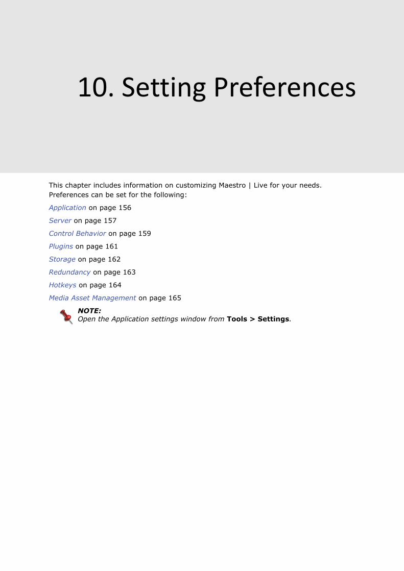
10. Setting Preferences
This chapter includes information on customizing Maestro | Live for your needs. Preferences can be set for the following:
Application on page 156
Server on page 157
Control Behavior on page 159
Plugins on page 161
Storage on page 162
Redundancy on page 163
Hotkeys on page 164
Media Asset Management on page 165
NOTE:Open the Application settings window from Tools > Settings.

156
10
. Set
tin
g P
refe
ren
ces
Application
The Startup settings allow you to choose actions to take when Maestro | Live is started. The Logging settings allow you to choose what items will be saved to the log.
Automatic Login
Select this check box to start Maestro | Live without displaying the Connect to Maestro | Live Server dialog box. When cleared, you must confirm connection details in the Connect to Maestro | Live Server dialog box (see Starting Maestro | Live on page 13).
Load Production
Select this check box to open the defined production upon startup. When cleared, Maestro | Live Controller opens in the state it was when last closed.
Play Control
Select this check box to set a control to play upon startup.
Logging The Client Log is created as a file that lists errors, warnings, etc. to allow troubleshooting errors in the application.The log file is saved in the Maestro | Live\Client folder as Maestro | Live.log.In the Logging settings, select the relevant check box to define which entry types are added to the log
Application |

10
. Setting P
references
Server
The Server settings allow you to configure initial client settings upon opening Maestro | Live (see Starting Maestro | Live on page 13) and to set clock preferences (the clock must be set in order to work with playlists and timing controls).
Here, you can also set a global parameter at the application level, to be available for all productions.
Server and clock settings
Host Host name or IP address of the computer on which the server is installed.
NOTE:The name “localhost” is used when the Maestro | Live Server and Maestro | Live Client are installed on the same computer.
Port Port number must be 6900.
Synchronize When this check box is selected, the current client production is synchronized with the server data. When cleared, the client opens without loading the server’s currently opened production.
Server | 157

158
10
. Set
tin
g P
refe
ren
ces
Log Level Set which events are saved to the Server log, as follows:Off - No events are logged.Exceptions - Only application errors are logged.Important - Principle events and errors are logged.Log - All events and errors are logged.Verbose - All events, actions, and errors are logged.
Timebase Select the required video format time base.25 fps – used for PAL.29.97 fps and 30 fps – used for NTSC.
Get update every
Specify the update frequency of reading time from system clock.
Application Globals
Create global parameters that are available to all productions.
Server and clock settings
Server |

10
. Setting P
references
Control Behavior
The Cue settings allow you to determine system behavior when a control is cued. The Validation settings allow you to determine parameters for successful validation. The Playlist setting allows you to determine system behavior when a cued event is stopped. The event can be Reset or Stopped.
Default Cue Timeout
Set the time before cue fail notification is displayed.
Lock validate file on cue
Select this check box to prevent changes to file validation when an item is cued.
Fail CUE on assigned Render Units disconnected
Select this check box to display cue fail notification when a referenced render unit is disconnected. When cleared, no notification is displayed.
Fail CUE when graphics not loaded
Select this check box to display cue fail notification when referenced graphics have not loaded. When cleared, no notification is displayed.
Fail CUE on query error
Select this check box to display cue fail notification when a query error occurs. When cleared, no notification is displayed.
Fail CUE on File Management error
Select this check box to display cue fail notification when a file management error occurs.
Validate successfully on empty path
When this check box is selected, event/playlist is validated when containing an empty path. When cleared, validation fails if an empty path is found.
Control Behavior | 159

160
10
. Set
tin
g P
refe
ren
ces
Validate successfully only when associated devices are connected
When this check box is selected, event/playlist is validated only when all referenced devices are connected. When cleared, validation does not verify device state.
Playlist Globak Settings
Determine system behavior when a cued event is stopped. The event can be Reset or Stopped
Control Behavior |

10
. Setting P
references
Plugins
This list displays a list of plugins currently in use in Maestro | Live.
Plugins | 161

162
10
. Set
tin
g P
refe
ren
ces
Storage
In the Storage settings, you can determine where productions and production elements are saved.
Storage settings
Make UID Case Sensitive
Enable this option if you want the device and control UIDs to be case-sensitive.
Server-side connection
Enable server-side connection to the configured storage. The Maestro | Live Client always requires a connection to the storage, while the Server only requires it in two scenarios:• events are loaded by Automation Protocols, • redundancy is configured.
Storage Type File Storage: defines a structured location where productions and elements are stored. The default location is defined upon installation. If you change this path, you must click Create Storage Structure. (If you do not create a storage structure in the new directory, data is saved to the original path defined upon installation.)
Database Storage: When you choose this option, you must indicate what database you are using. Below, enter the required database server connection information.
Storage |

10
. Setting P
references
Redundancy
In the Redundancy settings, set up a redundancy system to run as a backup for the current system.
Port Set the communication port of the redundancy system.
Database Location - set the SQL server location, for example ControlPC01\CYBERGRAPHICS.Name - set the DB Name.User - set the SQL username.Password - set the SQL password.Name/ID - set a UID for the redundancy instance.
Start Start running the configured redundancy system. This can be done here, or from the tool icons (see Tools Icons on page 20).
Backup Destination
Set the Host and Port to use to send a playlist.
Update Backup
Load the Blend playlist to backup systems with the same play state.
Redundancy | 163

164
10
. Set
tin
g P
refe
ren
ces
Hotkeys
In the Hotkey settings, you can set keyboard shortcuts to control a number of playout operations in the Production window for the Maestro | Live client and for individual controls within the production.
The Hotkey settings are context-sensitive; if you open them from the application settings, all options are displayed. If you open the Hotkeys dialog box from a control, the control is selected.
NOTE:To remove the hotkey for any function, select the ShortCut and click Remove.
To set a hotkey:
1. Select the action for which you want to set a keyboard shortcut, under Action.
Verify that the action is associated with the required control.
2. Press the keyboard combination.
The shortcut is displayed under Press shortcut keys:.3. Click Assign.
The shortcut is assigned to the action.
Hotkeys |

10
.Setting P
references
Media Asset Management
In the Media Asset Management window, you can set up your media sources. File Storage is added here by default, but you can also add a connection to MediaCentral | Cloud UX™ to browse for media in MediaCentral | Asset Management.
To add MediaCentral | Cloud UX as a media source:
1. In the Media Asset Management window, click on Add.
The Media Source Details window opens.
2. Enter the following parameters, as described below.
Name Set the name used to identify the media source on your connection list.
Host Enter the MediaCentral | Cloud UX IP address or its host name.
User Enter your MediaCentral | Cloud UX user name.
Media Asset Management | 165

166
10
. Set
tin
g P
refe
ren
ces
3. Click OK.
The connection is added to the list of media sources in the Media Asset Management window.
To activate a media source connection:
1. In the Media Asset Management window, select the Active check box next to the media source. When a media source is active, it will try to reconnect in case of a network failure.
The FileStorage connection is active by default.
To deactivate a connection, clear the Active check box.
NOTE:You cannot deactivate all sources. At least one media source needs to remain active.
To edit a media source connection:
1. Deactivate the connection by clearing the Active check box. The State of the connection becomes red and the Connection Message informs that it has been stopped.
2. Click on Edit. The Media Source Details dialog box opens.
3. Change the required parameters and click OK to close the window.
To delete a Cloud UX media source connection:
1. Deactivate the connection by clearing the Active check box. The State of the connection becomes red and the Connection Message informs that it has been stopped.
2. Click on Remove.
NOTE:You cannot remove the FileStorage media source.
Password Enter the password for the above MediaCentral | Cloud UX user.
Connection Attempts Interval
Set a time interval which will determine how Maestro | Live will try to reconnect in case the connection is lost. (default value: 1000 ms)
Media Asset Management |

11. Working withMediaCentral | Asset
Management
In this section:
Introduction on page 168
Activating a Connection to MediaCentral | Cloud UX on page 168
Connecting to and Browsing MediaCentral | Cloud UX Files on page 168

168
11. W
orki
ng w
ith M
edia
Cent
ral |
Ass
et M
anag
emen
t
Introduction
Maestro | Live offers direct integration with MediaCentral | Cloud UX right from its interface, enabling teams to find and access media easily across your platform—no matter where the assets are stored. Quickly locate and reuse relevant images, graphics templates, and clips from MediaCentral for use in your production without leaving Maestro | Live.
Activating a Connection to MediaCentral | Cloud UX
Before you can search for assets in MediaCentral | Cloud UX, you need to establish an active connection to the platform. To add and initialize a MediaCentral | Cloud UX connection, follow the steps listed in the Media Asset Management chapter.
Connecting to and Browsing MediaCentral | Cloud UX Files
If the MediaCentral | Cloud UX media source connection is correctly configured and activated, you can access the MediaCentral files from a GI parameter of the type Browse.
To create a Browse GI parameter:
1. Create a new GI parameter as described in To create a GI Parameter:.
2. In the Details section, set the Type to Browse.
3. In the Properties section, you can set a default value for this GI parameter. Select your MediaCentral | Cloud UX source from the drop-down list and double-click on the chosen asset.
4. Click OK.
The GI parameter is created.
5. Close the Action Editor, select the Action in the main panel and open the Inputs side panel. Your GI parameters are listed there.
Introduction |

11. Working w
ith MediaCentral | A
sset Managem
ent
To use a MAM asset in Maestro | Live:
1. In the Inputs panel, for the selected GI parameter, choose the Cloud UX instance which will be used to look for assets.
2. The Mam select window opens, where you can browse or search for assets.
3. If the Live Mode is enabled, double-clicking the asset will send it to the Input. If the Live Mode is disabled, you need to choose the asset and then press the Apply button (in the Inputs panel), to send the asset to the Input.
4. Immediately after the asset is send to the input, the resolve process is started. You can check the resolve status:
• In the Inputs panel - a colored frame is displayed around the value (yellow = resolve in progress, red = resolve error, no frame= succeeded).
• In the Media Asset Management panel (Tools > Media Asset Management) - the status is displayed. In this panel you can also click on the Resolve button to start the resolving process once again.
5. After the resolve is successfully finished, the indication frame disappears, and the action is ready to be played.
Connecting to and Browsing MediaCentral | Cloud UX Files | 169

170
11. W
orki
ng w
ith M
edia
Cent
ral |
Ass
et M
anag
emen
t
When MediaCentral | Cloud UX assets are used in an Advanced Playlist control, the main workflow remains the same. The only addition is that the graphic event will be marked as 'Failed to Validate' until the resolve process is not finished successfully (also the message will show the resolve progress - similar to validation of clip events).
Connecting to and Browsing MediaCentral | Cloud UX Files |

12. AAF File Support
In this section:
What is AAF and its usage in Maestro | Live on page 172
AAF in Media Composer on page 172
Prerequisites for using AAF files in Maestro | Live on page 173
Displaying AAF Files in Maestro | Live on page 175

172
12. A
AF
File
Sup
port
What is AAF and its usage in Maestro | Live
AAF (Advanced Authoring Format) is an industry-standard file format which facilitates exchange of media and compositions between various applications.
AAF in Media Composer
There are two types of markers: a simple Marker and a Spanned Marker. A simple Marker is a type of electronic bookmark which lets you find and identify specific frames. A Spanned Marker defines a segment of time in a clip or a sequence. In order to create clip segments, simply add in and out points in any Media Composer sequence and tag them as a marker with its name. Markers in Media Composer can have different colors, but only Red and Blue markers will be recognized by Maestro | Live. The Red Marker is used to divide clips into segments; while the Blue Marker allows to insert graphic events.
AAF, as implemented in Media Composer, provides a basic method for exporting files.
To export an AAF File:
6. Once you have created the sequence with your desired markers, navigate to bin window and right-click on the chosen sequence.
NOTE:The AAF file needs to be named identically as the clip file. The name can be changed directly in the Export As window or the sequence can be renamed beforehand.
7. Then choose Output - Export to File... and the Export As window pops up.
8. Press the Options... button at the bottom.
9. In the Export Settings window make sure that only AAF Edit Protocol, Include All Video / Data Tracks in Sequence and Include Audio Tracks in Sequence are enabled. Also check whether under the Video/Data Details and Audio Details
What is AAF and its usage in Maestro | Live |

12. AA
F File Support
sections, the Export Method is set to Link to (Don't Export) Media and all other checkboxes are disabled.
10.Now save the sequence as an AAF file, and all relevant information, such as metadata, will be saved without having to render and export the sequence as a clip.
Prerequisites for using AAF files in Maestro | Live
Before you can display the AAF segments in Maestro | Live, you need to inform a Clip Server device about the AAF files’ location.
To enable the AAF file support:
1. Go to Devices and select Clip Server Manager.
2. Select the preferred device and press .
What is AAF and its usage in Maestro | Live | 173

174
12. A
AF
File
Sup
port
3. Enable the checkbox next to the AAF Files folder and enter a local file system path or an UNC path, e.g.: G:\AAF or \\192.0.2.0\AAF, where the AAF files are stored.
NOTE:When working with AAF clips, the timebase of the AAF file and the one of the Maestro | Live application must be identical.
To change the timebase of the control application:
1. Go to Tools and select Settings.Under Server Settings, in the Clock section, choose the preferred timebase.
What is AAF and its usage in Maestro | Live |

12. AA
F File Support
Displaying AAF Files in Maestro | Live
Once the AAF segments are displayed in Maestro | Live, you can select the chosen file in the Clip Viewer and you will see the relevant metadata in the AAF File Description section:
What is AAF and its usage in Maestro | Live | 175

13. Browser
The Maestro | Live Browser is a separate, standalone application intended to be used for creating and previewing playlist events on any PC. The Browser uses RenderEngine to preview events, and then to save them. You can render graphics to a video file and save them as a a clip.
The events can later be loaded into a Maestro | Live playlist manually or via an automation system.
In this section:
Using the Browser on page 177
Browser Menus on page 181
Customizing the Layout on page 182
Maestro | Live Browser Settings on page 184

13
. Bro
wser
Using the Browser
To open the Browser:
■ Open the Browser application using the Maestro | Live Browser desktop icon.
The Browser window opens.
The following procedure outlines event creation in the Browser:
To create a new event:
1. Load the Action controls of the required production;
a. Select File > Open to open the Select Production dialog box.
Using the Browser | 177

178
13
. Bro
wse
r
b. Select a production, and click OK.
The production’s Action controls are loaded and displayed in the Production Controls tab.
3. Select an Action to execute in your event.
The Action’s GI parameters are displayed under Inputs.
4. Edit the Action as required, and click Apply.
Only GI parameters that were defined as external can be edited manually.
If the Action is connected to a data group control (in Maestro | Live), you can select the data group from the drop-down list, and select an item from the data group to use for the event.
NOTE:In order to see Data Groups, you must copy the file devices.xml from MaestroLive\Server\config to MaestroLive\Browser\config.
5. Click Load All to load the Action’s graphics in the Preview window.
6. Adjust the aspect ratio as required, in the Playout Control drop-down lists.
7. Cue & Play the Action to review it.
If required, set the event duration.
8. Click Save to save the Action as a playlist event with the specified parameters.
If you don’t assign a UID manually, one is assigned automatically.
The saved event is displayed in the Events tab.
Using the Browser |

13
. Bro
wser
Rendering Graphics as a Clip
The Render to file feature is for creating video format clips from rendered graphics.
To create a clip:
1. Select an event or control to render.
2. Click Render to file under Playout Control.
The Render to File dialog box is displayed.
3. Set the following:
Output Root Folder
Select the location where the result of the rendering should be placed.
File name Set the required name for the clip, or leave the default name.
Start / Stop Initialize or cancel the rendering.
Task Settings
Set the task settings, as described below:• Event UID - automatically filled with the selected event UID (if
it was selected).• Control Name - automatically filled with the selected action
name, or action name that is used by the selected event. • Duration - automatically set with the play time, but you can
also adjust it to the requested duration.• Preset - defines the output type (e.g. image sequence/video
file).• Layout - select the required layout.Once you have configured the required options, press on Render to begin the rendering. You can cancel it any time by pressing on Cancel.
Rendering Graphics as a Clip | 179

180
13
. Bro
wse
r
4. You can view the progress of the rendering. Once the rendering is complete, an appropriate message is displayed in the Render to file window.
Go to the output file by clicking on the Open button.
5. Click Close.
Rendering Graphics as a Clip |

13
. Bro
wser
Browser Menus
File menu
Tools Menu
Help Menu
New Open a new production to work in.
Open Open an existing production from the Maestro | Live storage.
Search Open the Search dialog box to search for assets according to defined parameters.
Switch User Open a dialog box to login with a different user name (for different user privileges), when using a MS SQL database for storage.
Exit Close the Browser.
Settings Open the Settings dialog box to set various preferences for the Browser. See Maestro | Live Browser Settings on page 184.
Global Parameters Viewer
Open the Global Parameters Viewer to view or edit global parameters.
Languages Set the GUI language from the available options. User defined names set in one language remain unchanged.You can create your own GUI translation files by copying and renaming one of the XML files in the \Client\Languages directory, and entering your own text.
Layouts Provides two default GUI configurations (with or without the Preview window), and enables you to edit and save your own GUI configuration. (Save is available after editing).
User Guide Open the Maestro | Live help.
About Display information about current version.
Browser Menus | 181

182
13
. Bro
wse
r
Customizing the Layout
You can set up the Browser window as required, and save different layouts using different names.
To change the layout:
1. From the Tools menu select Layouts > Edit Layouts.
The borders of the different panels are displayed as dotted lines.
2. Drag the lines to adjust the panels as required.
You can select one of the preset layouts on the right.
To hide a panel, us the X in the panel’s title bar. To display a hidden panel, right-click an empty area and select the required panel.
3. In the Tools menu, select Layouts > Save Layout As.
Customizing the Layout |

13
. Bro
wser
A dialog box opens.
4. Save your layout.
5. Open it from the list in the Tools menu.
Customizing the Layout | 183

184
13
. Bro
wse
r
Maestro | Live Browser Settings
Preferences
Server
Render Unit
Storage
Automatic Login
When selected, login is executed automatically upon startup. When cleared, login is manual.
Load layout When selected, the layout selected from the list is loaded upon startup. When cleared, the default layout is loaded.
Load production
When selected, the production selected from the list is loaded upon startup. When cleared, the browser is started without opening a production.
Group by When selected, when opening a production, the Controls in the production are listed according to the metadata parameter selected from the list. When cleared, the Controls in the production are listed in alphabetical order.
Load all graphics into RE
When selected, when opening a production, Load All is executed automatically. When cleared, graphics are not loaded automatically.
Load graphics into RE
When selected, when selecting a Control, only the graphics of the control are loaded to the Preview window. When cleared, graphics are not loaded.
Timebase Select the required video format time base for the clock.25 fps – used for PAL.29.97 fps and 30 fps – used for NTSC.
Render host Set Localhost or Remote to set where the Render Unit is running.
Remote render unit
Name or IP address of a remote render unit.
Render OS Select the OS of the machine where the Render Unit is running
File Storage The location where productions and elements are stored. Browse to the defined Maestro | Live production folder.
Database Storage
When you choose this option, you must indicate what database you are using. The File Storage option is for the MSSQL database.The Native Database option is for the Avid database. Below, enter the required connection information.
Maestro | Live Browser Settings |

13
. Bro
wser
Events
Panels
Logging
The Client Log is created as a file that lists errors, warnings, etc. to allow troubleshooting errors in the application.
The log file is saved in the Maestro | Live\Client folder as Maestro | Live.log.
In the Client Logging settings, select the relevant check box to define which entry types are added to the log.
Event naming method
Define the naming format for each event created in the Browser; name can include a prefix and an incremental number, or a manual name/number.
Take event duration from GI Parameter
Use the duration defined in the selected GI parameter as the event duration.
Button Visibility (Save Event tab)
Select which buttons to display in the Save Event options.
Predefined Filters (Explorer tab)
Define the default filtered display of the Controls in the Production Controls tab.
Maestro | Live Browser Settings | 185

186
13
. Bro
wse
r
Media Asset Management
In the Media Asset Management section, you can view all available MAM connections. You cannot add or remove connections here. At least one media source connection needs to be active and working.
Maestro | Live Browser Settings |

Appendix
This appendix contains the following section:
Browser Services on page 188
Available CallByName Commands on page 202

188
Ap
pen
dix
Browser Services
The Browser Services can work in two modes: an EXE application, or Windows service.
If you want to use the EXE type, you need to start the BrowserRESTApiEXE.exe application. The application can be started through Command Line with the 'id' parameter (e.g. BrowserRESTApiExe.exe id=ConfigurationName) that indicates, which configuration will be used in the service (see the Configuration paragraph).
To use the Windows service type, you need to register the Windows Service using a BAT file 'BrowserRESTApiWindowsService_InstallService_WithID.bat' with the optional parameter 'ID' used both as a part of the unique service name and the 'id' of a service configuration (see Configuration below). Afterwards, start the service using the Windows Services application. To uninstall the service, rename the BAT file to 'BrowserRESTApiWindowsService_UninstallService_WithID.bat' also with the optional parameter 'ID' (used to identify the proper service).
Configuration
Both Exe and Windows Service types need to be properly configured. The main configuration file is called 'Config.xml' and contains one default configuration, which will be used if the 'id' parameter is not specified.
You can save multiple configurations inside this XML file. Each configuration is a node called 'InstanceConfig' and should have a unique Id, Hostname and Port. For each configuration, you can set the following options:
• StorageSettings - specify if the storage type should be File System or Native Database and all other settings related to that storage.
• EventSettings - specify basic event settings.
• StartupSettings - specify, if any item should be loaded automatically when starting the service.
• LogLevel - specify the amount of details saved to the logs.
Each configuration has its own subdirectory (created by the user) named after the ID of that configuration. Inside, there should be two directories (also created manually):
• 'config' with the service configuration files,
• and 'log' with the log file.
You can copy all settings files inside the 'config' subdirectory from different settings e.g. from the 'default/config' directory and make any necessary changes inside these settings files.
TIP:To unblock a port in firewall, type in a command-line interface: netsh firewall add portopening TCP <port_no> "Open Port <port_no>".
Multiple Instances
You can start multiple instances of the Browser Services. To do that, pass the unique ID while starting the service. Each service has to work with the unique combination of a host name and a port.
Browser Services |

Ap
pen
dix
API Documentation
Production
POST /api/production Load specified item.
Response status OK (200)
DELETE /api/production Remove all loaded items.
No parameters
Response status OK (200)
GET /api/production/items Get all loaded items.
Parameter Description Type Data Type & Model type Type of items to be sent as query string
a response. Available values: Action, Pacer, DataGroup, Playlist, AdvancedPlaylist, All.
Response status OK (200) Response Body – list of items with basic description: [
{ "TypeEnum": "int", "TypeDescription": "string", "StorageParentGUID": "string", "UniqueID": "string", "Name": "string", "DateCreated": "datetime", "CreatedBy": "string", "DateModified": "datetime", "ModifiedBy": "string"
} ]
Parameter Description Type Data Type & Model body parameters Body with the description
of an item to be loaded. body {
"StorageId": "string" }
Browser Services | 189

190
Ap
pen
dix
GET /api/production/items/{id} Get the description of the specified item as an event.
Parameter id
Description ID of an item
Type path
Data Type & Model string
Response status OK (200) Response Body – item description as an event: {
"StorageParentGUID": "string", "UniqueID": "string", "DurationMS": 0, "Control": { "StorageGUID": "string", "UniqueID": "string", "Data": [
{ "Name": "string", "Type": "string", "Value": "string"
} ]
}, "Metadata": [ {
"GUID": "string", "Type": "Text", "Name": "string", "Value": "string"
} ], "AssociatedControls": [ {
"DurationMS": 0, "Control": { "StorageGUID": "string", "UniqueID": "string", "Data": [
{ "Name": "string", "Type": "string", "Value": "string"
} ]
} }
] }
Browser Services |

Ap
pen
dix
Event
GET /api/events Get all event items in the defined StorageId.
Parameter
Description Type
Data Type & Model
storageId Specify storageId if query string different than the default one.
Response status OK (200) Response Body – list of events with basic description: [
{ "TypeEnum": "int", "TypeDescription": "string", "StorageParentGUID": "string", "UniqueID": "string", "Name": "string", "DateCreated": "datetime", "CreatedBy": "string", "DateModified": "datetime", "ModifiedBy": "string"
} ]
POST /api/events Create an event based on the event description sent in the body.
Parameter Description Type Data Type & Model body
parameters Body with the event description.
{ EventDescription (EventDescription): The description of an event, EventOperationFlags (string): Event operation flag = ['None', 'ProcessControl'] }
EventDescription { StorageParentGUID (string): GUID of a parent, UniqueID (string): ID of the event, DurationMS (integer): Duration of an event in MS, Control (ControlDescription): Description of the base control, Metadata (Array[MetadataItem]): List of the additional metadata, AssociatedControls (Array[AssociatedControlDescription]): List of the associated controls }
ControlDescription { StorageGUID (string): GUID of the storage, UniqueID (string): ID of the control,
body { "EventDescription": {
"StorageParentGUID": "string", "UniqueID": "string", "DurationMS": 0, "Control": { "StorageGUID": "string", "UniqueID": "string", "Data": [ {
"Name": "string", "Type": "string", "Value": "string"
} ]
}, "Metadata": [ {
"GUID": "string",
Browser Services | 191

192
Ap
pen
dix
Data (Array[DataItem]): List of data items of the control }
MetadataItem { GUID (string): GUID of the metadata items, Type (string): Metadata type = ['Text', 'Numeric', 'DropDown', 'CheckBox', 'AutoFill', 'ReadOnly', 'CheckBoxTrueFalse', 'DateAndTime', 'Unknown'], Name (string): Metadata name, Value (string): Metadata value }
AssociatedControlDescription { DurationMS (integer): Duration of a control in MS, Control (ControlDescription): Description of the base control }
DataItem { Name (string): Item name, Type (string): Item type, Value (string): Item value }
"Type": "Text", "Name": "string", "Value": "string"
} ], "AssociatedControls": [ {
"DurationMS": 0, "Control": { "StorageGUID": "string", "UniqueID": "string", "Data": [
{ "Name": "string", "Type": "string", "Value": "string"
} ]
} }
] }, "EventOperationFlags": "None"
}
Response status OK (200) Response Body – newly created event: {
"StorageParentGUID": "string", "UniqueID": "string", "DurationMS": 0, "Control": { "StorageGUID": "string", "UniqueID": "string", "Data": [
{ "Name": "string", "Type": "string", "Value": "string"
} ]
}, "Metadata": [ {
"GUID": "string", "Type": "Text", "Name": "string", "Value": "string"
} ], "AssociatedControls": [
Browser Services |

Ap
pen
dix
DELETE /api/events/{eventId} Remove an event item.
Response status OK (200)
GET /api/events/{eventId} Get an event item description.
Parameter Description Type Data Type & Model eventId EventId required to get its path string
description.
storageId Specify storageId if query string different than the default one.
Response status OK (200) Response Body – description of the event: {
"StorageParentGUID": "string", "UniqueID": "string",
{ "DurationMS": 0, "Control": { "StorageGUID": "string", "UniqueID": "string", "Data": [
{ "Name": "string", "Type": "string", "Value": "string"
} ]
} }
] }
Parameter Description Type Data Type & Model eventId EventId required for the
removal. path string
storageId Specify storageId if different than the default one.
query string
Browser Services | 193
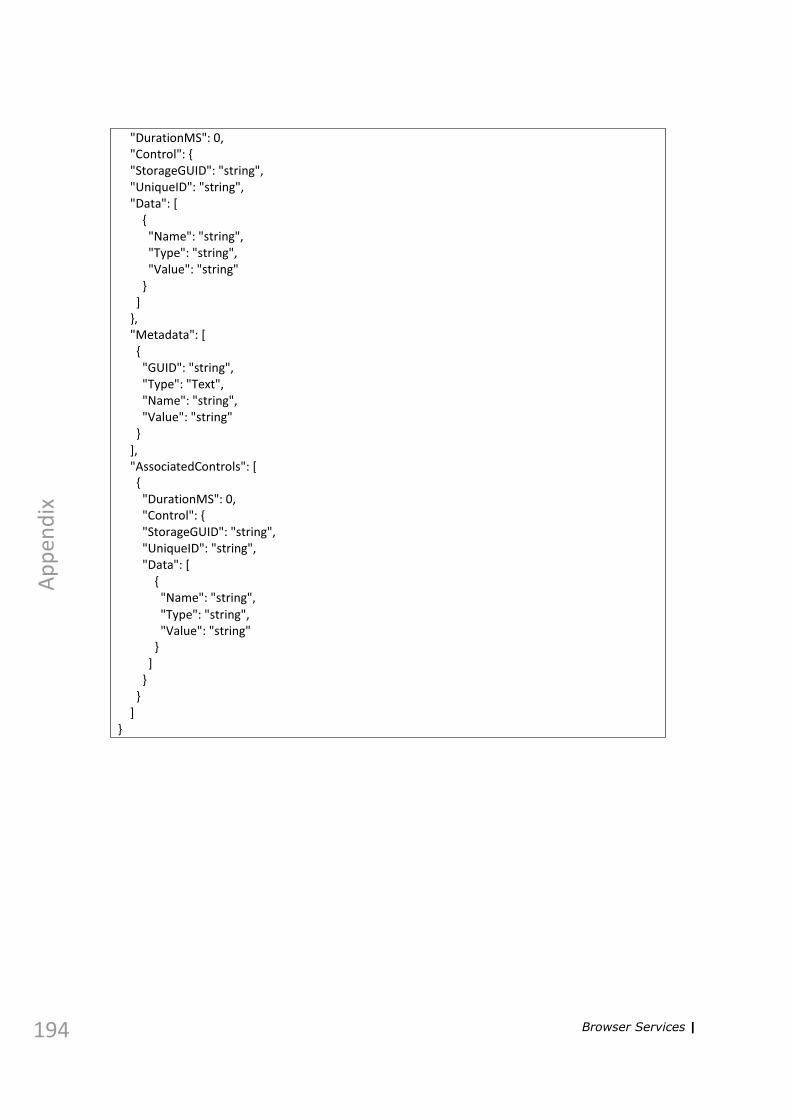
194
Ap
pen
dix
"DurationMS": 0, "Control": { "StorageGUID": "string", "UniqueID": "string", "Data": [
{ "Name": "string", "Type": "string", "Value": "string"
} ]
}, "Metadata": [ {
"GUID": "string", "Type": "Text", "Name": "string", "Value": "string"
} ], "AssociatedControls": [ {
"DurationMS": 0, "Control": { "StorageGUID": "string", "UniqueID": "string", "Data": [
{ "Name": "string", "Type": "string", "Value": "string"
} ]
} }
] }
Browser Services |

Ap
pen
dix
PUT /api/events/{eventId} Update an event based on the event description sent in the body.
Parameter Description Type Data Type & Model eventId EventId required for the update. path string
body Body with the event description. body { parameters "EventDescription": { { "StorageParentGUID": "string",
EventDescription (EventDescription): The description of an event, "UniqueID": "string", EventOperationFlags (string): "DurationMS": 0, Event operation flag = ['None', 'ProcessControl'] } "Control": {
"StorageGUID": "string", EventDescription { "UniqueID": "string", StorageParentGUID (string): GUID of a parent, "Data": [ UniqueID (string): ID of the event, { DurationMS (integer): "Name": "string", Duration of an event in MS, Control (ControlDescription): "Type": "string", Description of the base control, "Value": "string" Metadata (Array[MetadataItem]): List of the additional metadata, } AssociatedControls ] (Array[AssociatedControlDescription]): }, List of the associated controls } "Metadata": [
{ ControlDescription { "GUID": "string", StorageGUID (string): GUID of the storage, UniqueID (string): ID of the control, "Type": "Text", Data (Array[DataItem]): "Name": "string", List of data items of the control } "Value": "string"
} MetadataItem { ], GUID (string): GUID of the metadata items, "AssociatedControls": [ Type (string): { Metadata type = ['Text', 'Numeric', 'DropDown', "DurationMS": 0, 'CheckBox', 'AutoFill', 'ReadOnly', 'CheckBoxTrueFalse', 'DateAndTime', 'Unknown'], "Control": { Name (string): Metadata name, "StorageGUID": "string", Value (string): Metadata value } "UniqueID": "string",
"Data": [ AssociatedControlDescription { { DurationMS (integer): Duration of a control in MS, "Name": "string", Control (ControlDescription): "Type": "string", Description of the base control "Value": "string" }
} DataItem { ] Name (string): Item name, Type (string): Item type, } Value (string): Item value } } ]
}, "EventOperationFlags": "None"
}
Response status OK (200) Response Body – updated event:
Browser Services | 195
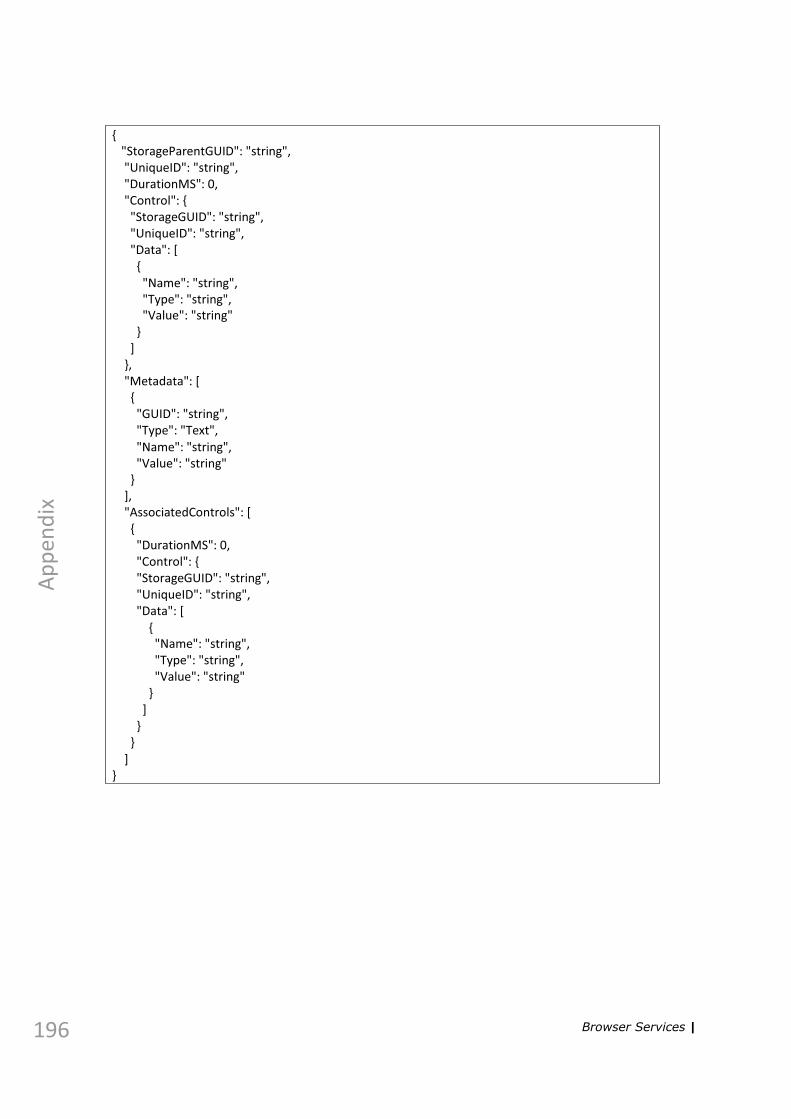
196
Ap
pen
dix
{ "StorageParentGUID": "string", "UniqueID": "string", "DurationMS": 0, "Control": { "StorageGUID": "string", "UniqueID": "string", "Data": [
{ "Name": "string", "Type": "string", "Value": "string"
} ]
}, "Metadata": [ {
"GUID": "string", "Type": "Text", "Name": "string", "Value": "string"
} ], "AssociatedControls": [ {
"DurationMS": 0, "Control": { "StorageGUID": "string", "UniqueID": "string", "Data": [
{ "Name": "string", "Type": "string", "Value": "string"
} ]
} }
] }
Browser Services |

Ap
pen
dix
Account
POST /api/account/login Log in to the service.
Response status OK (200)
GET /api/account/logout Log out of the service.
no parameters
Response status OK (200)
GET /api/account/refreshticket Refresh the authentication ticket to maintain the session.
no parameters
Response status OK (200) with new authentication cookie
Parameter Description Type Data Type & Model body parameters Body with the
credentials. body {
"Password": "string", "User": "string"
}
Browser Services | 197

198
Ap
pen
dix
Timelines
POST /api/timelines Create a new timeline.
Response status OK (200) Response body – a GUID of the newly created timeline
DELETE /api/timelines/{timelineGUID} Remove a timeline.
Parameter Description Type Data Type & Model timelineGUID GUID of the timeline used path string
to create preview.
Response status OK (200)
GET /api/timelines/{timelineGUID}/events Get all events added to a timeline.
Parameter Description Type timelineGUID GUID of the timeline used path
to create preview.
Data Type & Model string
Response status OK (200) Response body – a list of all added events: [ {
"EventUID": "string", "StartPoint": 0, "Duration": 0
} ]
Browser Services |

Ap
pen
dix
POST /api/timelines/{timelineGUID}/events Add an event to a timeline.
Parameter Description Type Data Type & Model timelineGUID GUID of the timeline used path string
to create preview.
body parameters Body with the timeline body { event description. "EventUID": "string", { "StartPoint": 0, EventUID (string): UID of an "Duration": 0 event to be added, } StartPoint (integer): start position of the event in MS, Duration (integer): duration of the event in MS }
Response status OK (200)
DELETE /api/timelines/{timelineGUID}/events/{eventUID} Remove an event from a timeline.
Response status OK (200)
Parameter Description Type Data Type & Model timelineGUID GUID of the timeline used
to create preview. path string
eventUID UID of an event to be removed.
path string
Browser Services | 199

200
Ap
pen
dix
POST /api/timelines/{timelineGUID}/preview Render a timeline.
Parameter Description Type Data Type & Model timelineGUID GUID of the timeline used path string
to create preview.
body parameters Body with the render job body { request description. "Start": 0, { "End": 0 Start (integer): start time of the } render in MS, End (integer): end time of the event in MS }
Response status OK (200) Response body – a render job description: {
"Guid": "string", "Path": "string", "Progress": "string", "Length": "string", "CompletedState": bool, "CompletedStateMessage": "string"
}
GET /api/timelines/preview/{jobGUID} Get the render status.
Parameter jobGUID
Description GUID of the render job.
Type path
Data Type & Model string
Response status OK (200) Response body – a render job description: {
"Guid": "string", "Path": "string", "Progress": "string", "Length": "string", "CompletedState": bool, "CompletedStateMessage": "string"
}
Browser Services |

Ap
pen
dix
POST /api/timelines/preview/{jobGUID} Stop the render job.
Parameter jobGUID
Description GUID of the render job.
Type path
Data Type & Model string
Response status OK (200)
DELETE /api/timelines/preview/{jobGUID} Delete the render job.
Parameter jobGUID
Description GUID of the render job.
Type path
Data Type & Model string
Response status OK (200)
Browser Services | 201

202
Ap
pen
dix
Available CallByName Commands
Target UID Command Data Description
KernelAPI CtrlPlay UID of playable control+data
CtrlCue UID of playable control+data
DeviceConnect UID of device
DeviceDisconnect
UID of device
GlobalVarsGet Name of global variable
Assign value of one Global parameter to a different Global parameter
GlobalVarsSet Name of global variable + value for this variable
Set the value of a Global parameter
UID of playable control
CtrlPlay Data
CtrlCue Data
CtrlUpdateAndPlay Data
CtrlSetDefaults Data
UID of device Connect
Disconnect
Reset
UID of GPIO control
Register GPIO Line Number (number)+GPIO State List (True of False)+UID of the playable control
Registers the control in the invocation list
Unregister GPIO Line Number (number)+GPIO State List (True or False)+index of the control in the invocation list (number)
Removes the control from the invocation list
Available CallByName Commands |

Ap
pen
dix
UID of Pacer control
UpdateData Executes any query and updates the Pacer items with the results
PacerGoToLine Database line number to go to.
Changes the current line in the database assigned to the Pacer to the data in the specified cell.
GetPacerLine Assign the current line number to a global or GI parameter.
GetPacerLoop Assign the current loop number to a global or GI parameter.
GetPacerTotalLine Assign the total number of lines to a global or GI parameter.
GetPacerTotalLoop Assign the total number of loops to a global or GI parameter.
UID of Action control
SetKey Name of key+Value for key
Sets the value of the key defined for the Action control.
SetGIParamValue GI_param,~:global:~
Sets the current value of a GI parameter, data delimiter is ",".
CtrlSetName UID of playable control + name
Sets the name of the specified control.
CtrlSetImage UID of playable control + image path
Sets the image of the specified control.
CtrlSetColor Sets the color of the specified control.
Target UID Command Data Description
Available CallByName Commands | 203

204
Ap
pen
dix
CtrlSetSelectHotkey
UID of playable control + string defining the hotkey.
Sets the “Select” hotkey for the specified control.
CtrlSetSelectAndPlayHotkey
UID of playable control+string defining hotkey.
Sets “SelectAndPlay” hotkey for specified control.
Target UID Command Data Description
Available CallByName Commands |

Index
Numerics
3DPlay server controller 13
A
actioncontrol 60editor 62
addingadvanced playlist 60automation mediator 41, 48control 60database 34, 36GI parameter 80global parameter 82GPIO device 38graphic control 51, 54, 57HDVG 30new render unit 30
advanced playlist 60control 123
advanced playlist control 60animations 115application settings 18archiving productions 16, 27assigning graphics to channel/device 63assigning render unit 63automation mediator
control 60editor 95
automation systems 41, 95
C
calculator 67clip viewer control 60, 105command
list of 66removing 79
configuringautomation mediator 41, 48automation system 41, 95database 34GPIO device 38graphic control 51, 54, 57HDVG 30
connectingall devices 19automation mediator 41, 48database 34, 36GPIO device 38graphic control 51, 54, 57HDVG 30render unit 32
controlcreating 60manager 61pausing 68
creatingcontrol 60GI parameter 80global parameter 82new render unit 30panels 24
cue tab 77
D
data groupcontrol 60, 105editor 91
data source manager 33data streamer
editor 96data tab 83database query 83defining
database 34, 36database query 83new render unit 30
details tab 62devices
bar 20connecting all 19disconnecting all 19
disconnectingall devices 19automation mediator 41, 48database 34, 36GPIO device 38graphic control 51, 54, 57HDVG 30
docking control/elements 18, 20, 21
| 205

206
E
editingaction control 62automation mediator control 95data group 91data streamer control 96GPIO control 94pacer control 86
events 136exporting production for earlier version 16
G
GI parameter 80GI parameter editor 80, 84global parameter 82global parameters viewer 19GPIO
control 60, 105editor 94manager 38
graphic item tab 66, 86grouping commands 68GUI language 19
H
hotkeys 61, 103, 124, 152, 164
I
if-then commands 113importing production from earlier version 16inputs list 18interface language 19
K
keyboard shortcuts 61, 103, 124, 152, 164
L
language 19layout editor 24line manager 86lines tab 88loading graphics 17logic 114
M
merging productions 16
O
openingautomation mediator manager 41, 48control manager 61GPIO manager 38graphic control manager 51, 54, 57render unit manager 30
P
pacer control 60, 105pacer editor 86panels 24pausing a control 68play tab 77playing
animations 115scenes 117
playlistcontrol 142validation 140
playlist events see eventsplugin 161production window 15
Q
query 83refining 84
query tab 87
R
refining database query 84removing
command 79render unit 31
renaming a production 26render unit
assigning to control 63manager 30
RenderEngine, starting and stopping 20router event 137running
tickers 116
|

S
savingcontrol outside production 28production 26production for earlier version 16to new location 162
scene 117scheduling individual events 124sending content to ticker 88server controller 13set clock 123setting
interface language 19ticker content 88
setting up a query 83settings 18showing
hotkeys 18, 20inputs 18
simulating GPIO device 40snapping to grid 18, 20starting
3DPlay 13RE 20
storage 162streaming protocols 45synchronizing 156, 157synchronizing with server 157
T
testing GPIO device 40tickers 116tied events 137timing individual playlist events 124
U
UID 31, 35, 42, 46, 49, 52, 55, 58, 63, 165unloading
graphics 30graphics from render unit 32scene 117
using logic 114
V
validation (playlist) 140vslot
clearing 117
W
workspace 77
Z
zipping productions 16, 27
| 207