Embed Size (px)
Citation preview

0 EN715 User Guide AVerMedia Technologies, Inc www.avermedia.com
AVerAI EN715 Carrier Board and Box PC Designed for NVIDIA
® Jetson Nano
TM / Xavier NX
AVerMedia Technologies, Inc.
No. 135, Jian 1st Rd., Zhonghe Dist., New Taipei City 23585, Taiwan
Tel: 886-2-2226-3630
Fax: 886-2-3234-4842
Sales and Marketing: Contact
Technical Support: Professional User

1 EN715 User Guide AVerMedia Technologies, Inc www.avermedia.com
Table of Contents
Preface ......................................................................................................................................................... 3
Disclaimer _____________________________________________________________________________________ 3
Technical Support ____________________________________________________________________________ 3
Contact Enquiry ______________________________________________________________________________ 3
Download User Manual ______________________________________________________________________ 3
Revision History ______________________________________________________________________________ 3
AVerMedia Global Offices ___________________________________________________________________ 4
Limited Product Warranty __________________________________________________________________ 5
Copyright Notice______________________________________________________________________________ 5
Trademark Acknowledgement_______________________________________________________________ 6
ESD Warning _________________________________________________________________________________ 6
1.0 Introduction .................................................................................................................................... 7
1.1 Product Specifications ___________________________________________________________________ 8
1.2 OPTION ACCESSORY _________________________________________________________________ 9
2.0 Product Overview ........................................................................................................................ 10
2.1 Block Diagram _________________________________________________________________________ 10
2.2 Front View and Back View of EN715 _________________________________________________ 11
2.3 Front View and Three-Quarter View of EN715 BoxPC _____________________________ 12
2.4 Connector Summary ___________________________________________________________________ 12
2.5 Switch Summary _______________________________________________________________________ 14
3.0 Feature Description ................................................................................................................... 15
3.1 Connector and Switch Locations _____________________________________________________ 15
3.2 SerDes (V-by-One® HS) _______________________________________________________________ 16
3.3 Jetson™ Nano/NX Module Connector _______________________________________________ 17
3.4 Fan Power connector __________________________________________________________________ 17
3.5 MIPI CSI-2 DPHY Lanes _____________________________________________________________ 18
3.6 RTC Battery Connector _______________________________________________________________ 20
3.7 OTG/USB Micro-Type Connector ____________________________________________________ 20

2 EN715 User Guide AVerMedia Technologies, Inc www.avermedia.com
3.8 20-Pin GPIO expansion ________________________________________________________________ 21
3.9 Power Supply Connector ______________________________________________________________ 22
3.10 Gigabit Ethernet Connector ________________________________________________________ 22
3.11 USB 3.1 Gen 1 Type-A Connector #1 and #2 ______________________________________ 23
3.12 HDMI OUTPUT ____________________________________________________________________ 23
3.13 Optional Function Selection ________________________________________________________ 24
3.14 Micro SD Card Slot _________________________________________________________________ 24
3.15 Other Switches and Jumpers _______________________________________________________ 24
4.0 Installation ................................................................................................................................... 25
4.1 BSP Setup Instructions ________________________________________________________________ 25
5.0 Software ........................................................................................................................................ 26
6.0 Force Recovery Mode ................................................................................................................ 27
7.0 Power Consumption ................................................................................................................... 28
8.0 Option Accessory Drawings ...................................................................................................... 28
8.1 Power Cable, Fan Module and Adapter and Power Cord __________________________ 28
9.0 Dimension Drawings and Assembly Drawings ..................................................................... 34
9.1 Dimension Drawings of EN715 _______________________________________________________ 34
9.2 Dimension Drawing of EN715 Box PC _______________________________________________ 35

3 EN715 User Guide AVerMedia Technologies, Inc www.avermedia.com
Preface
Disclaimer
The information contained in this user manual, including but not limited to any product
specification is subject to change without notice. AVerMedia assumes no liability for any
damages incurred directly or indirectly from any technical or typographical errors or omissions
contained herein or for discrepancies between the product and the user manual.
Technical Support
If you experience the difficulty after reading this manual and/or using the product, please contact
the reseller from which you purchased the product. In most cases, the reseller can help you with
the product installation and the difficulty you encountered.
In case the reseller is not able to resolve your problem, our highly capable global technical
support team can certainly assist you. Our technical support section is available 24 hours a day
and 7 days a week through our website, with the click here. For more contact information, you
may find it in the section of AVerMedia Global Offices.
Contact Enquiry
For more information of our products, pricing, and order placement, please fill in our inquiry
form here, we will contact you within 24 hours.
Download User Manual
Please click the link here to download the file of this user manual from AVerMedia website.
Revision History
Revision Date Updates
Version 1.0 May 15, 2020 Release user manual

4 EN715 User Guide AVerMedia Technologies, Inc www.avermedia.com
AVerMedia Global Offices

5 EN715 User Guide AVerMedia Technologies, Inc www.avermedia.com
Limited Product Warranty
AVerMedia provides the one-year product warranty. Should this product, in AVerMedia's
opinion, fail to be in the good working order during the warranty period, AVerMedia will, at its
option, repair or replace it at no charge, provided that the product has not been subjected to abuse,
misuse, accident, disaster, or non-AVerMedia authorized modification or repair.
You may obtain the warranty service by delivering this product to an authorized AVerMedia
business partner or to AVerMedia along with the proof of purchase. Product returned to
AVerMedia must be pre-authorized by AVerMedia with an RMA (Return Material Authorization)
number marked on the outside of the package and sent prepaid, insured, and packaged for the safe
shipment. AVerMedia will return the product by prepaid shipment service.
The limited product warranty is only valid over the serviceable life of the product. This is
defined as the period during which all components are available. Should the product prove to be
irreparable, AVerMedia reserves the right to substitute an equivalent product if available or to
retract the product warranty if no replacement is available.
The above product warranty is the only warranty authorized by AVerMedia. Under no
circumstances will AVerMedia be liable in any way for any damages, including any lost profits,
lost savings, or other incidental or consequential damages arising out of the use of, or inability to
use, such product.
Copyright Notice
The information contained in this document is subject to change without notice. AVerMedia shall
not be liable for errors contained herein or for incidental consequential damages in connection
with the furnishing, performance, or use of this material. This document contains proprietary
information that is protected by copyright. All rights are reserved. No part of this document may
be photocopied, reproduced, or translated to another language without the prior written consent
by AVerMedia.

6 EN715 User Guide AVerMedia Technologies, Inc www.avermedia.com
Trademark Acknowledgement
AVerMedia acknowledges all the trademarks, registered trademarks, and/or copyrights referred to
in this document as the property of their respective owners. Not listing all possible trademarks or
copyright acknowledgments does not constitute the lack of acknowledgment to the rightful
owners of the trademarks and copyrights mentioned in this document.
ESD Warning
Electronic components and circuits are sensitive to Electrostatic Discharge (ESD). When
handling any circuit board assemblies including AVerMedia AVerAI products, it is highly
recommended that ESD safety precautions can be observed. ESD safe best practices can include,
but are not limited to the following ones.
1. Leave the circuit board in the antistatic package until it is ready to be installed.
2. Use a grounded wrist strap when handling the circuit board. At a minimum, you need to touch
a grounded metal object to dissipate any static charge, which may be present on you.
3. Avoid handling the circuit board in the carpeted areas.
4. Handle the board by the edges and avoid the contact with the components.
5. Only handle the circuit boards in ESD safe areas, which may include ESD floor and/or table
mats, wrist strap stations, and ESD safe lab coats.

7 EN715 User Guide AVerMedia Technologies, Inc www.avermedia.com
1.0 Introduction
AVerMedia AVerAI EN715 includes three fully featured carrier boards and one associated Box
PC’s which is all developed for NVIDIA® Jetson NanoTM (Version B01) / Xavier™ NX modules.
AVerAI EN715 provides not only the access to a great list of latest interfaces on Xavier™ NX
modules but also one RJ-45 interface and one RTC battery as the function enrichment.
EN715 provides one 4Kp60 HDMI video output, two USB 3.0 ports, one GbE RJ-45 port,
20-pins GPIO expansion, and one Micro-B USB 2.0 port for recovery. It also comes with a
single-mold PCB terminal block module for easy power connection.
Operating with NVIDIA® Jetson NanoTM / Xavier™ NX module and the rich I/O functions,
AVerAI EN715 is the perfect choice in building a compact, high performance AI edge computing
platform for the intelligent video analytics applications.

8 EN715 User Guide AVerMedia Technologies, Inc www.avermedia.com
1.1 Product Specifications
Model EN715-BBC3 EN715-BBC2
Compatibility NVIDIA® Jetson Nano™ (Version B01)/Xavier™ NX module
Networking 1x GbE RJ-45
Display Output 3840 x 2160 at 60Hz
Temperature
Operating temperature 0°C~70°C
Storage temperature -40°C ~ 85°C
Relative humidity 40 °C @ 95%, Non-Condensing
MIPI Camera
Inputs
-2x 2 lane MIPI CSI-2, 15 pin FPC
1mm Pitch Connector
-1x 4 Lane MIPI CSI-2, 36 pin FPC
1mm Pitch Connector
-2x 2 lane MIPI CSI-2, 15 pin FPC
1mm Pitch Connector
USB 1x USB 2.0 Micro-B for recovery
2x USB 3.0 Type-A
Storage 1x micro-SD card slot
GPIO Expansion 20 pins: 2x I2C, 1x UART, 9x GPIOs
Input Power 3.5mm Screw Terminal; 9V~19V is recommended.
Buttons Power and Recovery
RTC Battery Support RTC battery and Battery Life Monitoring by MCU
Dimension/ Weight W: 87mm x L: 70.6mm x H: 27.3mm (3.43” x 2.78” x 1.07”), Weight: 70g
Accessory DC Jack Power Extension Cable (5.5 x 2.5mm x 30cm)
Certifications CE, FCC, KC

9 EN715 User Guide AVerMedia Technologies, Inc www.avermedia.com
1.2 OPTION ACCESSORY
Item EN715-BBC3 EN715-BBC2
NVIDIA® Jetson Nano™ (Version B01) / Xavier NX
Fan Module
-Heat sink with Fan (Dimension: 56 x 40.8 x 20 mm) for Jetson Nano™ (Version B01)
-Heat sink with Fan (Dimension: 59 x 40.8 x 30 mm) for Xavier™ NX
module
AC Adaptor 12V, 5A
Power cord EU/JP/TW/US/CN/UK
MIPI Camera
Camera Module Manufacturer: APPRO.PHO
– For 15 pin MIPI connector
B-04: IMX179(8M)MIPI, 1080P(30fps)
C-04: IMX290(2M)MIPI, 1080P(30fps)
C-05: IMX290(2M)+ISP(YUV), 1080P(30fps)
– For 36 pin MIPI connector
B-03: IMX334(4K) MIPI, 4K(30/60fps)
B-13: IMX334(4K)+ISP(YUV) , 4K(30fps)
A-03: IMX290(FHD) V-by-One® HS, 1080P(60fps)
A-06: IMX334(4K) V-by-One® HS x1, 4K(30fps)

10 EN715 User Guide AVerMedia Technologies, Inc www.avermedia.com
2.0 Product Overview
2.1 Block Diagram

11 EN715 User Guide AVerMedia Technologies, Inc www.avermedia.com
2.2 Front View and Back View of EN715

12 EN715 User Guide AVerMedia Technologies, Inc www.avermedia.com
2.3 Front View and Three-Quarter View of EN715 BoxPC
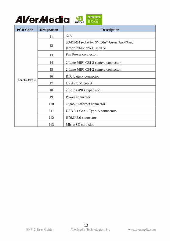
2.4 Connector Summary
13 EN715 User Guide AVerMedia Technologies, Inc www.avermedia.com
PCB Code Designation Description
EN715-BBC2
J1 N/A
J2 SO-DIMM socket for NVIDIA® Jetson Nano™ and
Jetson™XavierNX module
J3 Fan Power connector
J4 2 Lane MIPI CSI-2 camera connector
J5 2 Lane MIPI CSI-2 camera connector
J6 RTC battery connector
J7 USB 2.0 Micro-B
J8 20-pin GPIO expansion
J9 Power connector
J10 Gigabit Ethernet connector
J11 USB 3.1 Gen 1 Type-A connectors
J12 HDMI 2.0 connector
J13 Micro SD card slot

14 EN715 User Guide AVerMedia Technologies, Inc www.avermedia.com
PCB Code Designation Description
EN715-BBC3
J1 4 Lane MIPI CSI-2 camera connector
J2 SO-DIMM socket for NVIDIA
® Jetson Nano™ and
Jetson™XavierNX module
J3 Fan Power connector
J4 2 Lane MIPI CSI-2 camera connector
J5 2 Lane MIPI CSI-2 camera connector
J6 RTC battery connector
J7 USB 2.0 Micro-B
J8 20-pin GPIO expansion
J9 Power connector
J10 Gigabit Ethernet connector
J11 USB 3.1 Gen 1 Type-A connectors
J12 HDMI 2.0 connector
J13 Micro SD card slot
2.5 Switch Summary
Designation Description
SW3 RECOVERY button
SW4 POWER on button
SW5 Fan PWM controller/Auto Power on

15 EN715 User Guide AVerMedia Technologies, Inc www.avermedia.com
3.0 Feature Description
3.1 Connector and Switch Locations
J3
J1
J2
J6
J10
J5 J4
J11
J8
J12
J7
J9
SW5
5
J13
SW3
SW4
SW3

16 EN715 User Guide AVerMedia Technologies, Inc www.avermedia.com
3.2 SerDes (V-by-One® HS)
Function MIPI camera module connector
Location J1
Type Description WAFER_1*36PIN_0.5㎜_180°
Manufacturer and
Part Number PINREX 979-44-93610A_ZIF FPC
Mating Connector 4 Lane MIPI CSI-2 camera connector (36PIN)
PIN OUT

17 EN715 User Guide AVerMedia Technologies, Inc www.avermedia.com
3.3 Jetson™ Nano/NX Module Connector
Function Provide connection with NVIDIA® Jetson
Nano™ / Xavier™ NX
Location J2
Type Description SOCKET_DDR4
SO-DIMM_260PIN_90°
Manufacturer
and Part Number Foxconn ASAA826-EASB0-7H
Mating
Connector
NVIDIA® Jetson Nano™(Version B01) /
Xavier™ NX module
Pinout
Please refer to NVIDIA Jetson Nano™ /
Xavier™ NX and AGX Xavier™
System-on-Module datasheet for pinout
details.
Remarks https://developer.nvidia.com/ embedded/downloads
3.4 Fan Power connector
Function Fan Power Connector
Location J3
Type Description WAFER_1*4PIN_1.25㎜_90°
Manufacturer
and Part Number ACES 50271-0040N-001_BLACK
Pinout
Pin # Description
PIN 1 GND
PIN 2 Power +5V
PIN 3 FAN_TACH
PIN 4 FAN_PWM
Remarks None

18 EN715 User Guide AVerMedia Technologies, Inc www.avermedia.com
3.5 MIPI CSI-2 DPHY Lanes
Function MIPI camera module connector
Location J4 , J5
Type
Description WAFER_15PIN_1㎜_90°
Manufacture
r and Part
Number
CHAMPWAY AFA07-S15FCA-HF_FPC
ZIF-LOWER
Mating
Connector 2 Lane MIPI CSI-2 camera connector (15Pin)
Pinout
J4
PIN# Description PIN# Description
Pin1 GND Pin9 CSI0_CLK_P
Pin2 CSI0_D0_N Pin10 GND
Pin3 CSI0_D0_P Pin11 MIPI2_PWDN
Pin4 GND Pin12 CAM2_MCLK
Pin5 CSI0_D1_N Pin13 CSI0_I2C_SCL
Pin6 CSI0_D1_P Pin14 CSI0_I2C_SDA
Pin7 GND Pin15 +3V3_MIPI
Pin8 CSI0_CLK_N

19 EN715 User Guide AVerMedia Technologies, Inc www.avermedia.com
J5
PIN# Description PIN# Description
Pin1 GND Pin9 CSI2_CLK_P
Pin2 CSI2_D0_N Pin10 GND
Pin3 CSI2_D0_P Pin11 MIPI2_PWDN
Pin4 GND Pin12 CAM2_MCLK
Pin5 CSI2_D1_N Pin13 CSI2_I2C_SCL
Pin6 CSI2_D1_P Pin14 CSI2_I2C_SDA
Pin7 GND Pin15 +3V3_MIPI
Pin8 CSI2_CLK_N

20 EN715 User Guide AVerMedia Technologies, Inc www.avermedia.com
3.6 RTC Battery Connector
Function RTC battery for module
Location J6
Type Description 2.0mm wire-to-board header 02P type
Manufacturer
and Part Number Pinrex, 721-94-02TWR9
Mating
Connector Tyu, TU2001HNO-02
Pinout
Pin # Description
PIN1 3V Power
PIN2 GND
Remarks RTC Battery: MITSUBISHI, CR2032 3V
3.7 OTG/USB Micro-Type Connector
Function OTG programming recovery
Location J7
Type Description USB micro-type B female connector
Manufacturer
and Part Number Fullglory, FG-MCB-111440
Mating
Connector
Any USB standard Micro-type
interface cable or device.
Pinout Please refer to USB Micro-type
standard.
Remarks None

21 EN715 User Guide AVerMedia Technologies, Inc www.avermedia.com
3.8 20-Pin GPIO expansion
Function General-purpose input/output)
Location J8
Type Description 2x I2C, 1x UART, 9x GPIOs
Manufacturer and
Part Number 光桀_PHPME006-100ARRH
Mating Connector 20-Pin GPIO expansion
Pinout

22 EN715 User Guide AVerMedia Technologies, Inc www.avermedia.com
3.9 Power Supply Connector
Function Power Supply
Location J9
Type Description Socket_Terminal Block_1*2PIN_90°
Manufacturer and
Part Number DECA MB332-350M02
Mating Connector DC 5.5 x 2.5 mm Power cable
Pinout
PIN# Description Color
#1 12V Red
#2 GND Black
Remarks None
3.10 Gigabit Ethernet Connector
Function 1Gb Ethernet connector, used to connect
to the host system.
Location J10
Type Description RJ45 8P8C single-port with LED
Manufacturer and
Part Number Champway, 8188D-B514-00200
Mating Connector Any RJ45 plug with Cat5, Cat5e, Cat6
type cabling.
Pinout Comply with Ethernet standards.
Remarks None

23 EN715 User Guide AVerMedia Technologies, Inc www.avermedia.com
3.11 USB 3.1 Gen 1 Type-A Connector #1 and #2
Function USB 3.1 Gen 1 Type-A connector #1 & #2
Location J11
Type Description Dual-port USB 3.1 Gen 1 Type-A female
connector
Manufacturer and
Part Number Foxconn, UEA1112C-4HK1-4H
Mating Connector Any USB 3.1 standard Type-A interface
cable or device.
Pinout Please refer to USB 3.1 Gen 1 standard.
Remarks None
3.12 HDMI OUTPUT
Function HDMI output connector
Location J12: HDMI
Type Description HDMI Type-A female connector
Manufacturer and
Part Number Compupack, ACNHM220028-001
Mating Connector Any HDMI standard Type-A interface
cable or device.
Pinout Please refer to HDMI standard.
Remarks None

24 EN715 User Guide AVerMedia Technologies, Inc www.avermedia.com
3.13 Optional Function Selection
Function Fan PWM controller/Auto Power on
Location SW5
Type Description 4 SPST DIP switch
Manufacturer and
Part Number
DIPTRONICS IN OFF-SWITCHING
0.025A/24VDC
Pinout
SW Description ON
S1 Fan PWM controller Fan always on
S2 N/A N/A
S3 Auto power on Auto power on disabled
S4 Test mode off Test mode on (for factory use)
Remark None
3.14 Micro SD Card Slot
Function Micro SD Card
Location J13
Type Description SOCKET_MICRO SD
CARD_9PIN_90°_SMD
Manufacturer and
Part Number Fullglory, FG-0011BAAS09A
Pinout Refer to MicroSD card standard
Remark None
3.15 Other Switches and Jumpers
Other switches and jumpers listed on the boards but not mentioned in this manual are reserved
for the internal use by AVerMedia. They are not open to the client application.

25 EN715 User Guide AVerMedia Technologies, Inc www.avermedia.com
4.0 Installation
1. Check and ensure all the external system power supplies are turned off.
2. Install NVIDIA® Jetson Nano™ / Xavier™ NX module onto the SO-DIMM connector (J2).
Check and be sure to follow the manufacturer’s instructions for the proper installation of the
mounting hardware, heat sink or heat spreader, fan, and any other applicable requirements
from the associated manufacturers.
3. Install the necessary cables for the application. The cables can include the following ones. For
the additional information of these mentioned cables, please refer to 8.0 Cable Assembly in
this manual.
Power cable to the PCB terminal block module on the carrier board.
HDMI video display cable to HDMI video output connector (J12).
Mouse and keyboard cables to USB connectors (J11).
MicroSD card to MicroSD card slot (J13)
4. Connect the included power cable to the PCB terminal block module.
5. Connect the power cable to the power adapter.
6. Turn on the power adapter. (Please be reminded NOT to power on the system by plugging in a
live power.)
4.1 BSP Setup Instructions
BSP (board support package) file: EN715-R1.0.*.4.*.tar.gz
https://drive.google.com/drive/folders/11DBr14jZCZTtk8zJ-BormrY-cY8PIFeg
Default login username/password of the BSP is nvidia/nvidia
If you have difficulties to access the BSP download link, please visit AVerMedia website at
https://www.avermedia.com/professional/download, or contact technical support at
https://www.avermedia.com/professional/technical_support or e-mail us at
[email protected] for further assistance.
BSP Installation steps for NVIDIA Jetson board: (Important Note: Please backup your
personal files before re-flashing BSP)
After you download the BSP file and put the file in a Linux PC, please refer to the steps below
to re-flash BSP.
1. Let the JETSON Nano Xavier NX board initiate recovery mode.
You have to keep pressing “Recovery” button and then power on the NVIDIA Jetson board
to initiate recovery mode.

26 EN715 User Guide AVerMedia Technologies, Inc www.avermedia.com
When connecting a NVIDIA Jetson board to a Linux PC via a MicroUSB to USB cable, you
can check kernel messages with `dmesg` command in the Linux PC.
Once you see these messages in the kernel messages, this means that the NVIDIA Jetson
board is in the recovery mode.
[24685.229129] usb 1-7: Product: APX
[24685.229132] usb 1-7: Manufacturer: NVIDIA Corp
2. Using the commands below in the Linux PC to start re-flashing BSP.
$ sudo tar zxvf EN715-R1.0.*.4.*.tar.gz
$ cd JetPack_*.**/Linux_for_Tegra
$ sudo ./flash.sh Jetson-nano-emmc mmcblk0p1
Note: sudo is required to re-flash the BSP.
5.0 Software
For L4T (Linux for Tegra) BSP support and the other software support associated with
NVIDIA® Jetson NanoTM / Xavier™ NX module, please visit Avermedia website to contact our
technical support function. (https://www.avermedia.com/tw/support/contact)

27 EN715 User Guide AVerMedia Technologies, Inc www.avermedia.com
6.0 Force Recovery Mode
USB 3.l/OTG port of EN715 can be used to re-program NVIDIA® Jetson Nano™ / Xavier™ NX
module by using the other host system running NVIDIA JetpackTM, as the procedure described
below.
1. Power off the system. Ensure the system power must be completely OFF, instead of staying
in the suspend mode or the sleep mode.
2. Connect a USB cable from OTG USB port to the other host system which will be used to
re-program the new system file into NVIDIA® Jetson Nano™ / Xavier™ NX module.
3. Press and hold down Force Recovery Button and then power on the carrier board.
4. After three seconds, release Force Recovery Button.
5. NVIDIA® Jetson Nano™ / Xavier™ NX module will show up on the USB list of the host
system as a new NVIDIA target device.
6. After the system software is updated successfully, please ensure to power off the system. A
clean power-on will then revert OTG port back to the host mode.

28 EN715 User Guide AVerMedia Technologies, Inc www.avermedia.com
7.0 Power Consumption
Item Description Power Consumption
Theoretical Maximum System Power
Consumption 60W
Typical System Power Consumption
The power consumption under the normal
operating mode is depending on the
application software running with NVIDIA®
Jetson Nano™ Xavier NX module on the
carrier board or in the box PC’s.
8.0 Option Accessory Drawings
8.1 Power Cable, Fan Module and Adapter and Power Cord
Part Number 064APOWERBXS

29 EN715 User Guide AVerMedia Technologies, Inc www.avermedia.com
Nano Fan Module (Option)
Nano & Xavier NX Module (Option)

30 EN715 User Guide AVerMedia Technologies, Inc www.avermedia.com
Power Adapter 04131HGOUANK
64APOWERBRX-IPD (TW version)

31 EN715 User Guide AVerMedia Technologies, Inc www.avermedia.com
064APOWERBR2-IPD (US version)
064APOWERBRW-IPD (UK version)

32 EN715 User Guide AVerMedia Technologies, Inc www.avermedia.com
064APOWERBR5-IPD (EU version)

33 EN715 User Guide AVerMedia Technologies, Inc www.avermedia.com
064APOWERBSL (JP version)
064APOWERBR4-IPD (CN version)

34 EN715 User Guide AVerMedia Technologies, Inc www.avermedia.com
9.0 Dimension Drawings and Assembly Drawings
9.1 Dimension Drawings of EN715

35 EN715 User Guide AVerMedia Technologies, Inc www.avermedia.com
9.2 Dimension Drawing of EN715 Box PC