Embed Size (px)
Citation preview
Auxiliary measures applied in the tunnel construction of the Jonica motorway
Kolloquium Bauhilfsmassnahmen im Tunnelbau
ETH Zürich
Salvatore Lieto (ASTALDI S.p.A.)Paolo Perazzelli (ETH Zurich)
Project overview
Outline
Tunnel construction problems and design changes
Conclusions

Project overview
Taranto
Reggio Calabria
Jonica motorway (490 km)
Old motorway
Project overview
New motorway
Completed Sections
Launched
Assigned andnot launchedIn design
Taranto
Reggio Calabria

Project overview
Completed Sections
Launched
Assigned andnot launchedIn design
Taranto
Reggio Calabria
ASTALDI S.p.A. as General Contractor
Section 3 (Sibari - Roseto Capo Spulico)
Section 2 (Squillace - Simeri Crichi)
Section 1 (Gerace - Marina di Gioiosa Jonica )
Project overview
“Strada extraurbana principale – Cat. B (D.M. 5 novembre 2001) ”
Two-lane dual carriageway (lane width 3.75 m)
Velocity: 70 - 120 km/h
Total length 11.3 km

Project overview
Two-tube tunnelsn° 5; l = 2.6 km
Viaductsn° 7; l = 2.5 km
Two-tube cut-and-cover tunnelsn°7; l = 1.1 km
GERACE TRIGONI TIMPA PERGOLA LIMBIA
Costs of the project = 354 Ml €
3.753.75 9.75 m
1.750.5
I = 30-35 m
total length of the tunnels (L = 5.2 km)
H>2B
H = 4.5 m – 75 m
35% 35% 30%
2B>H>B H<B
ground surfacewater table
11.9 m
B
9.4 m
Project overview

Pl Monte Narbone formation (gravelly sand)
Ap Trubi formation (silty clay, clayey silt)
Pl 25%
Low
erP
leis
toce
neU
pper
Plio
cene
Sp Trubi formation (clayey sandy silt)
Hol
ocen
e
Qt Quaternary deposits (superficial deposits)
5% 20%
Ap
Qt
Pl
total length of the tunnels (L = 5.2 km)
Pl Ap
75%
Sp
z [m]
Project overview
Project overview
Outline
Tunnel construction problems and design changes
Conclusions

Tunnel construction problems and design changes
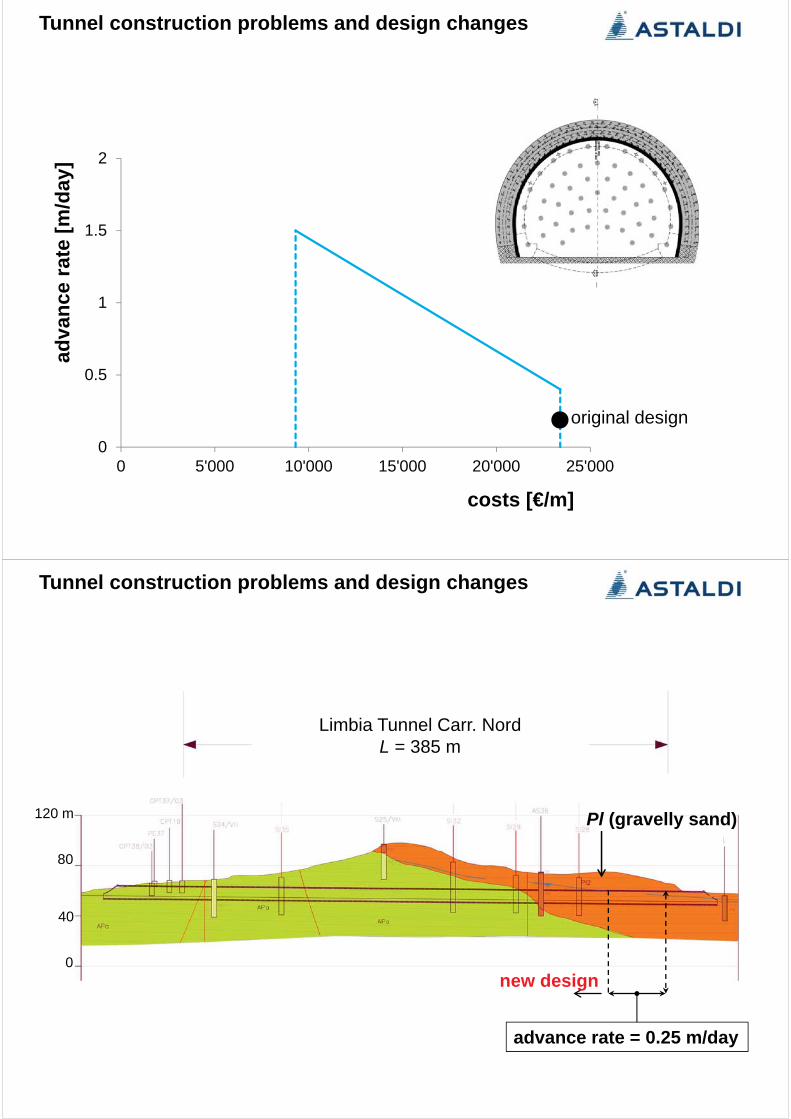
Limbia Tunnel Carr. NordL = 385 m
Pl (gravelly sand)
considered section
0
120 m
40
80
GravelSand
6040
0% 50% 100%Granulometry
0% 50% 100%granulometry
relative density Dr = 40 - 80% friction angle ’ = 30°– 45°DR=100%
DR=80%
0
100
200
300
400
500
6000 10 20 30 40 50 60 70 80
' v (k
Pa)
NSPT
Limbia
AS36
Limbia 1
’ v[k
Pa]
20 40 600600
400
200
0
NSPT
Dr [%] =10080
800
10
20
30
40
50
60
70
80
90
0,0 0,5 1,0 1,5 2,0 2,5 3,0 3,5 4,0 4,5 5,0
N S
PT
(kg/cm2)
Limbia
AS36
5002500 ’v [kPa]
80
40
20
0
60
NS
PT
3025
4540
35
cohesion c’ = 0
Tunnel construction problems and design changes
Pl : Monte Narbone formation (gravelly sand)
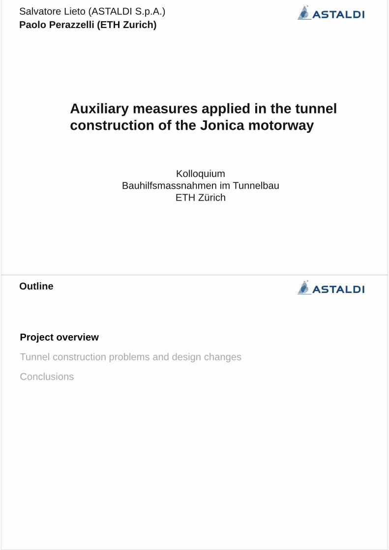
Tunnel construction problems and design changes
jet grouting columnsreinforcedwith fiberglass bolts
drainage24 m
drainage
1418
9
0.6 m 0.67
13.8 15.4
9.7
10.3 m
1.25
A
A
B
B
A-A B-B(after exc.)
0.72
C
C
C-C
1.5 m
0.4 m
0.8 m
shotcrete and steel ribs
length of round= 0.75 m Installation every 9 m of advance
jet grouting columnsreinforcedwith steel pipes
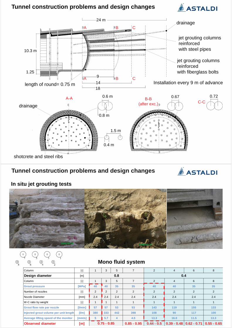
Tunnel construction problems and design changes
In situ jet grouting tests
Mono fluid systemColumn [-] 1 3 5 7 2 4 6 8
Design diameter [m]
Column [-] 1 3 5 7 2 4 6 8
Grout pressure [MPa] 40 40 35 35 40 40 35 35
Number of nozzles [-] 2 2 2 2 2 2 2 2
Nozzle Diameter [mm] 2.4 2.4 2.4 2.4 2.4 2.4 2.4 2.4
W-C ratio by weight [-] 1 1 1 1 1 1 1 1
Grout flow rate par nozzle [l/min] 57 57 53 53 143 119 155 133
Injected grout volume per unit length [l/m] 380 333 442 398 108 90 117 100
Average lifting speed of the monitor [mm/s] 5 5.7 4 4.5 13.3 16.0 11.5 13.3
Observed diameter [m] 0.85 - 0.95 0.44 - 0.5 0.39 - 0.48 0.62 - 0.71 0.55 - 0.65
0.8 0.4
0.75 - 0.85

Tunnel construction problems and design changes
9 m
5 m
10.3 m
10.3 m
9 m
Tunnel construction problems and design changes
9 m
9 m
5 m
10.3 m
10.3 m
0
0.5
1
1.5
2
0 5'000 10'000 15'000 20'000 25'000
adva
nce
rate
[m/d
ay]
costs [€/m]
original design
Tunnel construction problems and design changes
Tunnel construction problems and design changes
Limbia Tunnel Carr. NordL = 385 m
new design
advance rate = 0.25 m/day
Pl (gravelly sand)
0
120 m
40
80

Tunnel construction problems and design changes
10 m
4
1.212 m
A
A
A-A
1.25
drainage
jet grouting columns15-35 m
shotcrete and steel ribs
Tunnel construction problems and design changes
4
1.2
14.3
A
A
B
B
A-A
B-BC-C
CC
A B
A B
1.25
15-35 m
0.9 m
1 m
1.2 m
10 m
12 m
drainage
jet grouting columns
shotcrete and steel ribs

Tunnel construction problems and design changes
Dt =1.2 m1.2Lt = 2.1 m
Dm =1.04 m Lm =2.03 m
0.9
Dm =1.06 m Lm =2.07 m Dm =1.25 m Lm =2.15 m
Injected grout volume per unit length
Average lifting speedof the monitor
733 l/m 800 l/m 933 l/m
7.3 mm/s 6.7 mm/s 5.7 mm/s
4.5 m
0.5 m
Mono fluid system
Observed
Design values Dt =1.2 m1.2 Lt = 2.1 m Dt =1.2 m
1.2Lt = 2.1 m
0.9 0.9
Grout pressure 40 MPa
Number of nozzles 2
Nozzle Diameter 4 mm
W-C ratio by weight 1
Grout flow rate par nozzle 160 l/min
In situ jet grouting tests
Tunnel construction problems and design changes
Grout pressure 40 MPa
Number of nozzles 2
Nozzle Diameter 4 mm
W-C ratio by weight 1
Grout flow rate par nozzle 160 l/min
Injected grout volume per unit length 969 l/m
Average lifting speed of the monitor 5.5 mm/s
Mono fluid system Design values
Dt =1.2 m Lt = 2.1 m
Dm =1.04 m Lm =2.03 m
0.9
Dm =1.06 m Lm =2.07 m Dm =1.25 m Lm =2.15 m
Injected grout volume per unit length
Average lifting speedof the monitor
733 l/m 800 l/m 933 l/m
7.3 mm/s 6.7 mm/s 5.7 mm/s
4.5 m
0.5 m
Observed
Design values Dt =1.2 m Lt = 2.1 m Dt =1.2 m1.2Lt = 2.1 m
0.9 0.9
1.2 1.2
In situ jet grouting tests

Tunnel construction problems and design changes
12 m 12 m
12 m 12 m
shotcrete and steel ribs
0
0.5
1
1.5
2
0 5'000 10'000 15'000 20'000 25'000
adva
nce
rate
[m/d
ay]
costs [€/m]
new design
original design
Tunnel construction problems and design changes
Tunnel construction problems and design changes
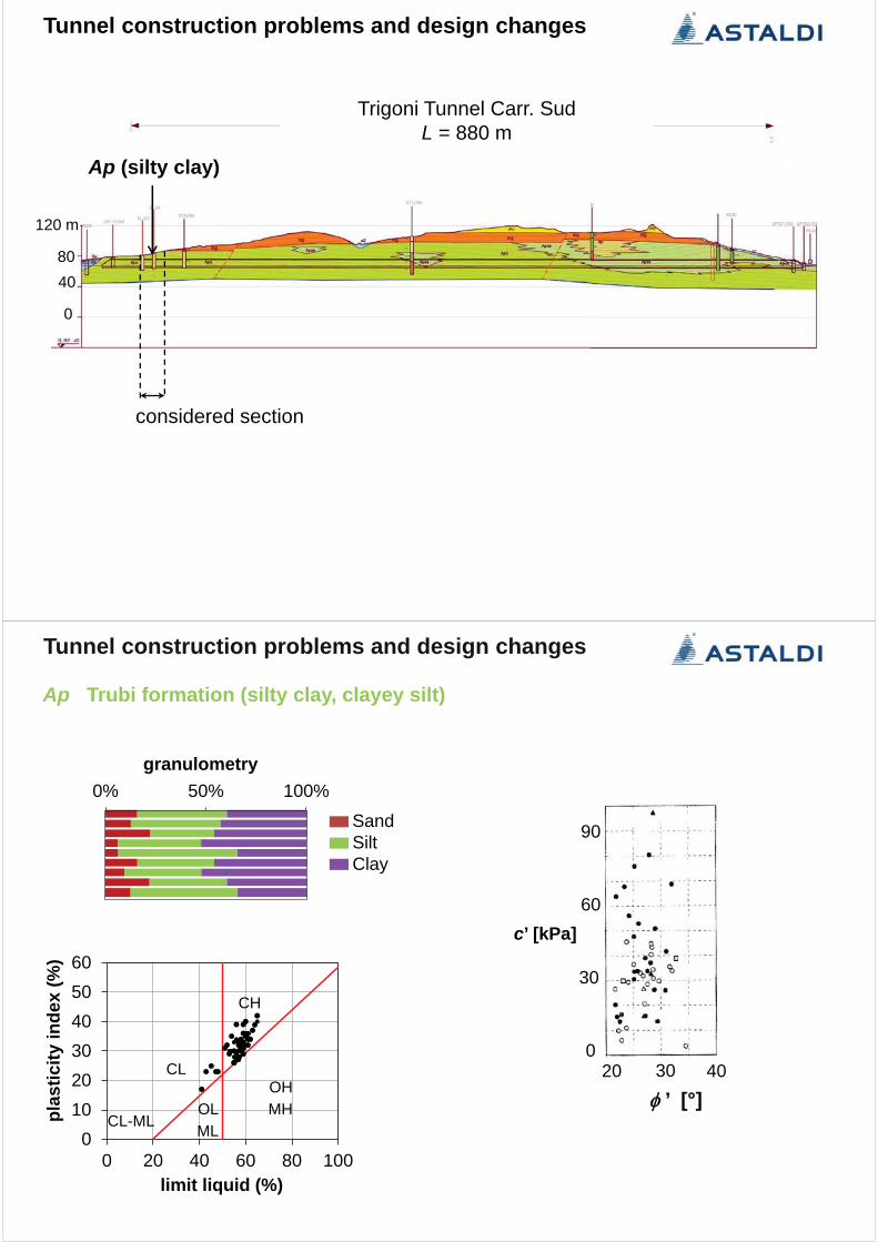
Trigoni Tunnel Carr. SudL = 880 m
considered section
0
120 m
4080
Ap (silty clay)
0% 50% 100%granulometry
SandSiltClay
0102030405060
0 20 40 60 80 100
plas
ticity
inde
x(%
)
limit liquid (%)
CH
MHOH
MLOL
CL-ML
CL
’ [°]30 4020
30
60
90
0
c’ [kPa]
Tunnel construction problems and design changes
Ap Trubi formation (silty clay, clayey silt)

Tunnel construction problems and design changes
16 18 m
12
9.8 m
1.25
12
A
A
B
B
A-A B-B (after exc.)
shotcrete and steel ribs
length of round = 0.75 m concrete invert
fiberglass bolts
grouted steel forepolings
60-110 fiberglass bolts(density 0.5 - 0.9 bolts/m2)
48 steel forepolings(spacing 0.4 m)
installation every 12 m of advance
Tunnel construction problems and design changes
surface fractures induced by the excavation
excavation faces
0.2 m
0monitoring stations in a distance of 24 m from the tunnel face
design threshold
uv
uh1+uh2 uh1 uh2
uv
re-profiling of the tunnel section inorder to guarantee the minimumclearance profile

0.0
0.5
1.0
1.5
2.0
0 5'000 10'000 15'000 20'000 25'000
adva
nce
rate
[m/d
ay]
costs [€/m]
original design
Tunnel construction problems and design changes
Tunnel construction problems and design changes
Trigoni Tunnel Carr. SudL = 880 m
new design
advance rate = 0.3 m/day
0
120 m
4080
Ap (silty clay)

Tunnel construction problems and design changes
A
A
CC 24 m
A-A
C-C
11 m
12-16 m
2.5 m
1.35 m1.5 m
1.35 m
1.5 m
13.7 m
shotcrete and steel ribs
length of round = 1 m concrete invert bored piles of lean concrete
bored piles of lean concrete
Tunnel construction problems and design changes
bottom of the bored piles
0.2 m
0monitoring stations in a distance of 24 m from the tunnel face
new design
tunnel convergences strongly reduced
uh1+uh2
uvuv
uh1 uh2

0.0
0.5
1.0
1.5
2.0
0 5'000 10'000 15'000 20'000 25'000
adva
nce
rate
[m/d
ay]
costs [€/m]
new design
original design
Tunnel construction problems and design changes
Tunnel construction problems and design changes
Gerace Tunnel Carr. NordL = 553 m
0
H = 4 – 6 mAp (clayey silt)Sp (clayey sandy silt)
considered sections
120 m
40
80

0% 50% 100%granulometry
SandSiltClay
’ [°]30 4020
30
60
90
0
c’ [kPa]
0% 50% 100%granulometry
SandSiltClay
’ [°]30 4020
30
60
90
0
c’ [kPa]
Tunnel construction problems and design changes
Ap Trubi formation (clayey silt)
Sp Trubi formation (clayey sandy silt)
Tunnel construction problems and design changes
16 18 m
12
9.8 m
1.25
12
A
A
B
B
A-A B-B (after exc.)
shotcrete and steel ribs
concrete invert
fiberglass bolts
grouted steel forepolings
60-110 fiberglass bolts(density 0.5 - 0.9 bolts/m2)
48 steel forepolings(spacing 0.2-0.4 m)
installation every 12 m of advance
length of round = 0.75 m

Tunnel construction problems and design changes
Face instability
0.0
0.5
1.0
1.5
2.0
0 5'000 10'000 15'000 20'000 25'000
adva
nce
rate
[m/d
ay]
costs [€/m]
original design
Tunnel construction problems and design changes

Tunnel construction problems and design changes
Gerace Tunnel Carr. NordL = 553 m
H = 4 – 6 mAp (clayey silt)Sp (clayey sandy silt)
new design
advance rate = 0.25 m/day
0
120 m
40
80
Tunnel construction problems and design changes
1.25
24-36 m
length of round = 1 m
14 m
21.5
3.1
15.2
groundsurface
lean concrete
9.8 m
A
A
A-A
shotcrete and steel ribs
Steel reinf. 6 15x15
concrete invert

Tunnel construction problems and design changes
Carr. Sud Carr. Nord
0.0
0.5
1.0
1.5
2.0
0 5'000 10'000 15'000 20'000 25'000
adva
nce
rate
[m/d
ay]
costs [€/m]
new design
original design
Tunnel construction problems and design changes

Conclusions
Contractual obligations (construction time and costs) & uncertainties in the design phase
flexibility in the execution phase