Embed Size (px)
Citation preview
AutoPAT MI 2143
User Manual Ver 1.0, Code no. 20 750 779
2
Distributor: Producer: Metrel d.d. Ljubljanska cesta 77 SI-1354 Horjul E-mail: [email protected] http://www.metrel.si © 2003 Metrel
Mark on your equipment certifies that this equipment meets the requirements of the EU (European Union) concerning safety and interference causing equipment regulations
No part of this publication may be reproduced or utilized in any form or by any means without permission in writing from METREL.

AutoPAT MI 2143
3
Table of contents
1 General description ........................................................................................................ 4
1.1 Warnings .................................................................................................................. 4
1.2 Applied standards .................................................................................................... 4
2 Instrument description .................................................................................................... 5
2.1 Front panel ............................................................................................................... 5
2.2 Connector panels ..................................................................................................... 5
2.3 Bottom ..................................................................................................................... 6
2.4 Indicator panel ......................................................................................................... 7
2.4.1 Warning indications ............................................................................................ 7
3 Instrument operation and application ............................................................................. 8
3.1 General .................................................................................................................... 8
3.2 Measurement limit values ........................................................................................ 9
3.3 Test setup .............................................................................................................. 10
3.4 Test procedure ....................................................................................................... 12
4 Technical specifications ............................................................................................... 13
5 Maintenance ................................................................................................................ 15
5.1 Periodic calibration ................................................................................................. 15
5.2 Fuse ....................................................................................................................... 15
5.3 Service ................................................................................................................... 16
5.4 Cleaning ................................................................................................................. 16
6 Instrument set and accessory ...................................................................................... 16
AutoPAT MI 2143
4
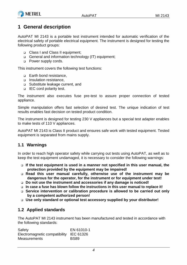
1 General description
AutoPAT MI 2143 is a portable test instrument intended for automatic verification of the electrical safety of portable electrical equipment. The instrument is designed for testing the following product groups:
Class I and Class II equipment; General and information technology (IT) equipment; Power supply cords.
This instrument covers the following test functions:
Earth bond resistance, Insulation resistance, Substitute leakage current, and IEC cord polarity test.
The instrument also executes fuse pre-test to assure proper connection of tested appliance.
Simple manipulation offers fast selection of desired test. The unique indication of test results enables fast decision on tested product condition.
The instrument is designed for testing 230 V appliances but a special test adapter enables to make tests of 110 V appliances.
AutoPAT MI 2143 is Class II product and ensures safe work with tested equipment. Tested equipment is separated from mains supply.
1.1 Warnings
In order to reach high operator safety while carrying out tests using AutoPAT, as well as to keep the test equipment undamaged, it is necessary to consider the following warnings:
If the test equipment is used in a manner not specified in this user manual, the protection provided by the equipment may be impaired!
Read this user manual carefully, otherwise use of the instrument may be dangerous for the operator, for the instrument or for equipment under test!
Do not use the instrument and accessories if any damage is noticed! In case a fuse has blown follow the instructions in this user manual to replace it! Service intervention or calibration procedure is allowed to be carried out only
by a competent authorized person! Use only standard or optional test accessory supplied by your distributor!
1.2 Applied standards
The AutoPAT MI 2143 instrument has been manufactured and tested in accordance with the following standards:
Safety EN 61010-1 Electromagnetic compatibility IEC 61326 Measurements BS89
AutoPAT MI 2143
5
2 Instrument description
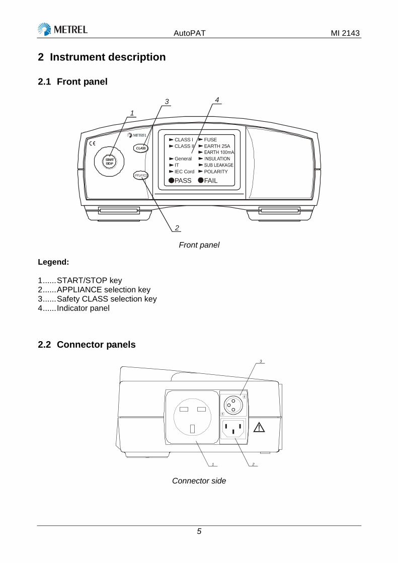
2.1 Front panel
CLASS
STARTSTOP
1
2
3 4
CLASS I
CLASS II
General
IT
IEC Cord
PASS
FUSE
EARTH 25A
POLARITY
FAIL
Front panel
Legend: 1 ...... START/STOP key 2 ...... APPLIANCE selection key 3 ...... Safety CLASS selection key 4 ...... Indicator panel
2.2 Connector panels
1 2
3
Connector side

AutoPAT MI 2143
6
4
Mains supply entry
Legend:
1 ...... Test socket 2 ...... IEC lead connector Warning! The connector input is only for test purposes; do not connect it to
mains supply! 3 ...... Earth bond connector, also used as an input for class II measurement of insulation Note: During IEC cord testing the earth bond clip need not be connected into earth
bond connector. 4 ...... Mains supply cord
2.3 Bottom
7
6
5
4
3
2
1
Bottom side
Legend:
1 ...... Plastic cover with rubber foot, for inclined position 2 ...... Screw. 3 ...... Label with measurement data. 4 ...... Fuse compartment cover. 5 ...... Information label. 6 ...... Fixing screw for fuse compartment cover (see chapter 11.2 Fuses for instructions on
fuse replacement). 7 ...... Rubber foot.
AutoPAT MI 2143
7
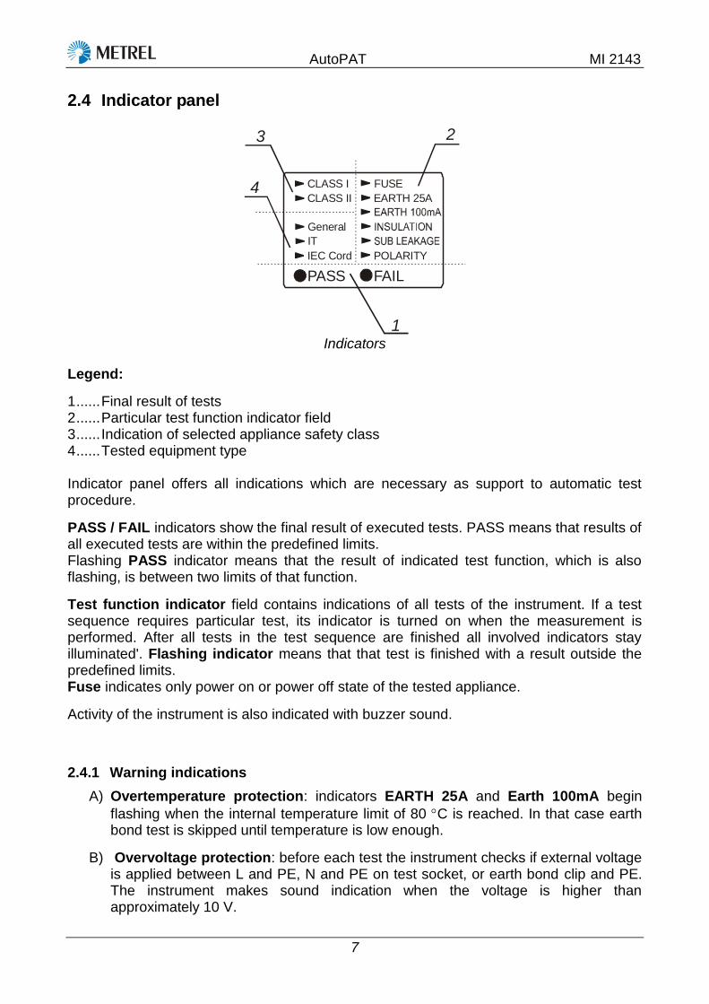
2.4 Indicator panel
1
23
4 CLASS I
CLASS II
General
IT
IEC Cord
PASS
FUSE
EARTH 25A
POLARITY
FAIL
Indicators
Legend:
1 ...... Final result of tests 2 ...... Particular test function indicator field 3 ...... Indication of selected appliance safety class 4 ...... Tested equipment type Indicator panel offers all indications which are necessary as support to automatic test procedure.
PASS / FAIL indicators show the final result of executed tests. PASS means that results of all executed tests are within the predefined limits. Flashing PASS indicator means that the result of indicated test function, which is also flashing, is between two limits of that function.
Test function indicator field contains indications of all tests of the instrument. If a test sequence requires particular test, its indicator is turned on when the measurement is performed. After all tests in the test sequence are finished all involved indicators stay illuminated'. Flashing indicator means that that test is finished with a result outside the predefined limits. Fuse indicates only power on or power off state of the tested appliance.
Activity of the instrument is also indicated with buzzer sound.
2.4.1 Warning indications
A) Overtemperature protection: indicators EARTH 25A and Earth 100mA begin
flashing when the internal temperature limit of 80 C is reached. In that case earth bond test is skipped until temperature is low enough.
B) Overvoltage protection: before each test the instrument checks if external voltage is applied between L and PE, N and PE on test socket, or earth bond clip and PE. The instrument makes sound indication when the voltage is higher than approximately 10 V.

AutoPAT MI 2143
8
3 Instrument operation and application
3.1 General
Automatic appliance testing with AutoPAT MI 2143 is very simple. It is just necessary to select class and type of appliance and start the test sequence. It is also possible to stop testing before completion by pressing START / STOP key again. In this case all test indicators are cleared.
Only those tests that are required for selected options are executed. Following is a short description of tests.
FUSE
This is pre-test only and is intended to detect if tested appliance is turned on. The instrument measures the impedance between L and N on test socket. If this impedance is too high then fuse indicator starts flashing. This pre-test does not have any influence on final PASS / FAIL decision. The reason is that very low power consumption appliances exist and thus they may have impedance higher than the limit.
EARTH 25A
Continuity test of PE connection is executed between test socket and earth bond clip. Earth bond clip has to be connected to accessible conductive parts that are connected to PE of the appliance supply cord. Test current of 25 A is required for most appliances in safety class I. The instrument contains two limits for this test.
EARTH 100mA
Some information technology (IT) appliances are very sensitive and could be damaged during standard PE continuity test as defined above. For this case the test current is limited to the nominal value of 100 mA.
INSULATION
For the CLASS I appliance the insulation resistance is measured between PE and shorted L and N conductors. The insulation resistance for CLASS II appliance is measured via earth bond clip instead of PE. Test voltage is 500 V nominal, only for CLASS I IT is 250 V. This test shows that the resistivity of the dielectric between accessible conductive part and L / N is high enough. For safety reason do not touch any accessible conductive parts with capacitance higher than 90 nF during insulation testing.
SUB LEAKAGE
Instead of measurement of leakage current with a real mains supply, this measurement is executed with separated voltage source with output voltage lower than safety limit. The source is connected between PE and shorted L / N conductors. Current into PE is measured and scaled to supply voltage.
POLARITY
This is a special test for detachable supply cords. Polarity in this case means correct connection between the terminals of a plug on one side and a socket on the opposite side.

AutoPAT MI 2143
9
NOTE! If polarity test with EU version of Autopat FAILS the first time, try to swap L and N terminals of tested IEC cord and repeat the test. If result is »PASS« at least one time, then IEC Cord is OK, otherwise it is not.
3.2 Measurement limit values
Appliances are designed for different purposes and various supply conditions. These ranges of conditions are covered by various general and product standards. A part of the standards are requirements against electric shock with test conditions and limit values. AutoPAT MI 2143 is designed for test conditions and compares results according to the standards mentioned in paragraph 1.3 Applied standards.
The following limit values are applied for the built-in functions:
230 V appliances Test function Appliance
type Safety class Limit values Test condition
FUSE General
CLASS I
30 k
40 V
CLASS II
IT CLASS I
CLASS II
EARTH 25 A General CLASS I 0.1 and 0.5 *
25 A
IEC cord CLASS I
EARTH 100 mA IT CLASS I 0.1 and 0.5 * 100 mA
INSULATION General
CLASS I 1 M 500 V
CLASS II 2 M
IT CLASS I 1 M 250 V
CLASS II 2 M 500 V
IEC cord CLASS I 1 M
SUB LEAKAGE General CLASS I 0.75 mA and 3.5 mA*
40 V
IT CLASS I
POLARITY IEC cord CLASS I <50 V
110 V appliances Test function Appliance
type Safety class Limit values Test condition
EARTH 25 A General CLASS I
0.1 and 0.5 * 25 A IEC cord CLASS I
EARTH 100 mA IT CLASS I 0.1 and 0.5 * 100 mA
INSULATION
General CLASS I 1 M
500 V CLASS II 2 M
IT CLASS I 1 M 250 V
CLASS II 2 M 500 V
IEC cord CLASS I 1 M
SUB LEAKAGE General CLASS I
0.75 mA and 3.5 mA* 40 V IT CLASS I

AutoPAT MI 2143
10
*Note: When test result is between two limit values then PASS and appropriate test function indicator are flashing. This is valid only if results of other test are acceptable. If result is out of the worst limit, FAIL indication is activated. In the case of flashing PASS indicator the tested appliance can still be acceptable for known reason, e.g. long mains cord.
In the case that numeric results are required, we recommend to test the appliance with AlphaPAT MI 2142, OmegaPAT MI 2140, or BetaPAT MI 2141.
3.3 Test setup
For regular testing it is required to prepare appropriate test setup. This setup must include all connections required for all measurements of particular appliance.
Following figures represent connections for testing appliance.
APPLIANCEUNDER
TEST
accessible conductive part connected to PE
Connection of the CLASS I appliance
Note: If appliance contains accessible conductive parts not connected to PE, then the test has to be repeated as for CLASS II appliance to test the insulation resistance of those parts to L / N.
CLASS II APPLIANCEUNDER TEST
accessible conductive part not connected to PE
Connection of the appliance of CLASS II

AutoPAT MI 2143
11
IEC CORDUNDERTEST
IEC cord connection
Connection of 110 V appliances Special adapter exists for testing 110 V appliances. The instrument automatically detects this adapter and calculates sub-leakage current to 110 V. Note: fuse pre-test and polarity (IEC cord) test are disabled.
Connecting 110 V adapter to the instrument
Measurement connections of tested 110 V appliances with this adapter are the same as mentioned above.

AutoPAT MI 2143
12
3.4 Test procedure
Flowchart for automatic testing of 230 V appliances:
START
CLASS &
Type
FUSE FUSE FUSE FUSE EARTH
25A
set to CLASS I
EARTH 25A
Insulation
Sub leakage
Insulation Insulation EARTH 100mA
Insulation
Sub leakage
Insulation
Polarity
FUSE result good
Rest results
flashing FUSE
PASS FAIL &
flashing
END END
All good
Yes
No
Any one bad
CLASS I, General
CLASS II, General
CLASS I, IT
CLASS II, IEC cord
CLASS I, IEC cord
CLASS II, IT
PASS &
flashing
END
Any one between its high and low limit
FAIL lits continously, flashing the test with bad result
PASS flashes, flashing the test with result between limits
PASS lits continously all involved tests lit continously

AutoPAT MI 2143
13
Flowchart for automatic testing of 110 V appliances:
START
CLASS &
Type
EARTH 25A
Insulation
Sub leakage
Insulation Insulation EARTH 100mA
Insulation
Sub leakage
Results PASS FAIL &
flashing
END END
All good Any one bad
CLASS I, General
CLASS II, General
CLASS I, IT CLASS II, IT
PASS &
flashing
END
Any one between its high and low limit
FAIL lits continously, flashing the test with bad result
PASS blinks, flashing the test with result between limits
PASS lits continously all involved tests lit continously
4 Technical specifications
Earth 25 A
Limit1 .................................... 0.1 0.03
Limit2 .................................... 0.5 10 %
Test current ........................... 25 A (100 m, mains supply voltage: 230 V a.c., ambient temperature: 25 °C)
Open circuit voltage .............. <6 V a.c. (mains supply voltage: 230 V a.c.) Test duration ......................... 5 s Output ................................... test socket (PE) to earth bond clip

AutoPAT MI 2143
14
Earth 100 mA
Limit1 .................................... 0.1 0.03
Limit2 .................................... 0.5 10 %
Test currents ......................... 100 mA (100 m, mains supply voltage: 230 V a.c., ambient temperature: 25 °C)
Open circuit voltage .............. <6 V a.c. (mains supply voltage: 230 V a.c.) Test duration ......................... 5 s Output ................................... test socket (PE) to earth bond clip Insulation resistance
Limit CLASS I ....................... 1 M
Limit CLASS II ...................... 2 M
Accuracy ............................... 10 %
Nominal voltage CLASS I IT . 250 V d.c. (+10 %, -0 %; 250 k)
Nominal voltage rests ........... 500 V d.c. (+10 %, -0 %; 500 k)
Test current ........................... > 1 mA at 500 k @ 500 V; > 1 mA at 250 k @ 250 V Short circuit current ............... 1.3 mA Test duration ......................... 5 s Output ................................... CLASS I: test socket (L+N to PE); CLASS II: test socket
(L+N) to earth bond clip Auto discharging after test. ... Yes Substitute leakage current
Limit ...................................... 0.75 mA, 3.5 mA
Accuracy ............................... 10 % Open circuit voltage .............. <50 V a.c. (mains supply voltage of 230 V a.c.) Short circuit current ............... <40 mA Test duration ......................... 2 s Output ................................... test socket (L+N to PE) Current scaled to .................. 230 V 110 V with 110 V appliance adapter Polarity test
Test voltage .......................... up to 80 V d.c. / < 1 mA Detects .................................. Pass, L-open, N-open, PE-open, L-N crossed, L-PE crossed,
N-PE crossed, L-N shorted, L-PE shorted, N-PE shorted, multiple faults
Output ................................... test socket and IEC cord Fuse pretest
Limit ...................................... 30 k
Accuracy ............................... 10 % Test voltage .......................... <50 V a.c. Output ................................... test socket (L to N)

AutoPAT MI 2143
15
General data
Rated supply voltage ............ 210 V 264 V, 50 Hz or 60 Hz Max. power consumption ...... 1.3 A
Fuse ...................................... T 1.6 A / 250 V, 5 22 mm
Overvoltage category ............ 300 V CAT II Protection classification ........ II (double insulation) Pollution degree .................... 2
Display .................................. LED indicators
Dimensions (w*h*d) .............. 26.5 cm × 11 cm × 18.5 cm Weight (without accessories) 2.76 kg
Storage temperature range ... -10 C +70 C
Reference / operating conditions
Temperature range ............... 0 C +40 C
Humidity range ...................... 80 % RH (0 C +40 °C), no condensing Reference voltage ................. 230 V
5 Maintenance
5.1 Periodic calibration
It is essential for all measurement instruments to be regularly calibrated. We recommend calibration once per 12 months.
5.2 Fuse
The instrument contains a mains fuse T 1,6 A / 250 V, 20 x 5 mm. It is located under fuse cover.
N
L
F1
T1,6A250V
K2
20311156 02.10.2003
F1
Mains fuse

AutoPAT MI 2143
16
To change the fuse:
Disconnect the instrument mains cord and all test leads before removing fuse cover!
Unscrew screws on fuse cover (pos 6 of bottom part) and remove cover Replace blown fuse with the same type as mentioned above Close fuse compartment and fix the fuse cover. Check the instrument.
5.3 Service
For repairs under or out of warranty please contact your distributor for further information. Unauthorized person is not allowed to open the AutoPAT MI 2143. There are no user replaceable components inside the instrument, except the fuse (refer to chapter 5.2 Fuse).
5.4 Cleaning
Use soft patch slightly moistened with soap water or alcohol to clean the surface of AutoPAT MI 2143. Leave the instrument to dry totally before using it. Notes:
Do not use liquids based on petrol or hydrocarbons! Do not spill cleaning liquid over the instrument!
6 Instrument set and accessory
Standard set
Instrument AutoPAT MI 2143 Soft carrying case Earth bond clip User manual Production verification data Conformity declaration
Optional accessory
110 V test adapter