Embed Size (px)
Citation preview

Electronic IndicatorOperating Manual Non-Analog Digital Display
3 Programmable Presets and 3 Programmable Ratios
TIR ABS INCRHOLD TOLERANCE
APPLY TRVL MOVE CHANGE
HOLD IN/MM 2ND TOL
OFF/MODEON/CLR
AUTO/OFFMADE IN USA
Extra-Large Number DisplayIncremental Measuring ModeSPC Cables USB, MTI, RS232Measuring System in English or MetricTravel ReverseAuto OffFloating ZeroRotating BezelInternal and External Serial NumbersT.I.R. with Low & High Storage Recall Power with Batteries
Additonal Power Through AC Jack or Data OutputProgrammable Lock CombinationUser Tolerance Settings (high & low)Up to 4 User Changeable ResolutionsInch/Metric Display ConversionLarge LCD DisplayMaximum Reading HoldDisplay/Freeze Reading HoldMinimum Reading HoldAbsolute/Preset Measuring Mode

2
TABLE OF CONTENTS
Power Source Options .............................................................................3
Button Functions ......................................................................................4
Summary Chart For Digital Button Actions .............................................5
Display-Operating Prompts & Conditions ................................................6
Power On/Off ...........................................................................................7
Auto-Off Toggle ........................................................................................7
Travel Reverse Toggle ..............................................................................7
Change Units ............................................................................................8
Hold Mode ................................................................................................8
Tolerance On/Off .....................................................................................9
Tolerance Settings ...................................................................................9
Set High Tolerance Number ...................................................................10
Set Low Tolerance Number....................................................................10
Set Absolute Number ............................................................................. 11
Lock Toggle ............................................................................................12
Lock Combination ..................................................................................12
Reset to Factory Defaults ......................................................................13
Verify Data I/O Type ...............................................................................13
Set Gage Resolution ..............................................................................14
TIR Mode ................................................................................................14
Ratio Mode .............................................................................................15
Custom Applications ..............................................................................16

3
CHOICE OF THREE POWER SOURCES
1. BatteriesThe lithium battery used in this indicator is an IEC standard, type CR2450. The indicators are shipped with the batteries installed.
Note: This indicator has an AUTO-OFF feature to conserve battery life. After 10 minutes of “no activity” (no key presses or spindle movement), the gage will turn itself off. This feature may be disabled if continuous operation is desired; see AUTO-OFF On/Off instructions in this book.
Installing BatteriesUsing a narrow screwdriver, gently pry under the tab on the left side of plastic bezel and slide out the battery tray as you turn the indicator face side down. Insert two batteries, “+” side up, into tray cavities, then slide the tray back into its bezel slot, taking care that the batteries stay in proper position.
2. AC AdapterFirst insert the mini-plug into the socket on the lower right side of the bezel, then plug the adapter into a wall outlet.
3. Data I/O ConnectorPower also may be provided through the data I/O connector, for special fixturing or applications where the indicator is integrated with another piece of equipment. A ripple-free 5 VDC regulated voltage source is required.

4
BUTTON FUNCTIONS
Key Function Controlled
OFF/MODE Off – turns indicator off MODE – controls absolute
numbers & display setup
ON/CLR On – turns indicator on CLR – resets the Lock Toggle,
Data I/O Type, gage resolution, and Display setup mode
HOLD Allows you to hold the value
on the display according to the specified Mode (MAX, MIN, FRZ)
IN/MM Controls the display units (default is English)
2ND Controls the Lock Toggle, Data I/O Type, gage resolution, Travel Reverse, Auto Off and Display setup mode
TOL Controls Low, High and On tolerance settings
MADE IN USA

5
BUTTONFUNCTION
PRIMARY SUBSIDIARY 2ND FUNCTION 3RD FUNCTION
HOLD Toggle on/off•
Select hold type (MAX, •MIN, FRZ) press and hold to step through selectionApply function•
Enter setting process •for ratios*
Enter resolution select process*•(2ND, ON/CLR, HOLD)•
IN/MMToggles between •inches, millimeters and X
Toggles travel reverse •(normal/reverse)
Resets to factory default •settings(2ND, ON/CLR, IN/MM)•
2ND Enables 2ND •functions
Move function•Verify data out put•(2ND, ON/CLR, 2ND)•
TOL Toggles tolerance •on or off
Select high or low to view •or set numbers*Change function•
Enter preset •setting process*
Toggles lock on and off; press •and release (2ND, ON/CLR, TOL)Enters user lock combination •setting mode (press and hold to access setting mode)*
ON/CLR Turn gage on•
Clears/resets display to •‘0’ or spindle position, or ‘abs’ number or ‘abs’ +/- spindle position
Enables •3RD function
OFF/MODE Turns gage off•
Select measurement mode •(INCR, ABS, TIR) press and hold to step through selection
Toggles auto-off •on and off
To turn on RATIO feature and •select RATIO 2ND, ON/CLR, OFF/MODE. Press and release to turn on, during button sequence hold down OFF/MODE to select RATIO position
* Note: apply, move and change are automatically active when in preset, lock and tolerance setting modes. Apply and change are automatically active when in resolution set mode.
SUMMARY CHART FOR DIGITAL BUTTON ACTIONS
Button actions should occur on the press of the button whenever possible. Some button presses will have the action occur on the release of the button press. For example, when the ‘ON/CLR’ button is used to clear the display, the action is to happen on the release of the button. When the ‘ON/CLR’ button is used as the 2nd function in a sequence of button pushes, the action can be on the press of the button. Whenever a button press requires a continuous press to scroll through some selection process, the action of the button needs to be on the release of the button.

6
MADE IN USA
HOLD
ON/CLR OFF/MODE
IN/MM
TIR ABS INCRTOLERANCE
APPLY TRVL MOVE CHANGE
AUTO/OFF
HOLD
2ND TOL
DISPLAY-OPERATING PROMPTS & CONDITIONS
AUTO-off is enabled to conserve
battery life.
Negative reading indicator. No sign is displayed for
positive readings.
Features and presets numbers
are locked
Indicator is in preset number setting function for ABS or
tolerance high or low numbers
Preset indicators Ratio indicators
Indicator ready for 2nd or 3rd function key entry
sequences
Displays IN for English (inch), or MM for Metric
Measuring Units.
For Total Indicator Runout (TIR), travel direction is
ignored. Peak (MAX) and valley (MIN) values are
available.
Display counts up with inward
spindle movement for INCR and ABS
measurement modes.
Display counts down with spindle movement
for INCR and ABS measurement modes.
Menu selection items under hold or
tolerance areas

7
OPERATING INSTRUCTIONS
Power On/OffTo turn the unit on, press and hold ON/CLR until indicator turns on. To turn off, press OFF/MODE.
Auto-Off ToggleTo turn the Auto-Off function on or off, press the 2ND button (2ND ICON should appear on the display). Press the OFF/MODE.
An hour glass appears at the left side of the display if AUTO OFF is active. If AUTO OFF is active the indicator will power off in 10 minutes with no activity (button press or spindle movement).
Travel Reverse ToggleTo change count direction:Press 2ND button, then press the IN/MM button. Note: When arrow is pointed down , the display counts down with inward spindle movement for INCR and ABS.
When the arrow is pointed up , display counts up with inward spindle movement. For most applications this is the normal setting.
MADE IN USA
HOLD
ON/CLR OFF/MODE
IN/MM
TIR ABS INCRTOLERANCE
APPLY TRVL MOVE CHANGE
AUTO/OFF
HOLD
2ND TOL
MADE IN USA
HOLD
ON/CLR OFF/MODE
IN/MM
TIR ABS INCRTOLERANCE
APPLY TRVL MOVE CHANGE
AUTO/OFF
HOLD
2ND TOL
1
1
2
2

8
OPERATING INSTRUCTIONS
Change UnitsTo change the display units, press the IN/MM button.
Default unit of measure is set at the factory for English or metric scales.
Hold ModeAllows you to hold the value on the display according to the specified mode.
Press HOLD to toggle hold mode on and off.
MAX – Holds and displays the highest reading attained.
MIN – Holds and displays the lowest reading attained.
FRZ – Holds and displays the reading displayed when HOLD is engaged.
To select type of HOLD (MAX, MIN, FRZ):Press HOLD until desired feature is flashing, then release HOLD.
Note: Pressing ON/CLR button resets indicator to spindle position except in FRZ; resets to zero
MADE IN USA
HOLD
ON/CLR OFF/MODE
IN/MM
TIR ABS INCRTOLERANCE
APPLY TRVL MOVE CHANGE
AUTO/OFF
HOLD
2ND TOL
MADE IN USA
HOLD
ON/CLR OFF/MODE
IN/MM
TIR ABS INCRTOLERANCE
APPLY TRVL MOVE CHANGE
AUTO/OFF
HOLD
2ND TOL

9
OPERATING INSTRUCTIONS
Tolerance On/OffPress TOL to toggle tolerance mode on and off. If no tolerances are programmed into the gage, then tol is displayed to indicate an invalid tolerance setting and the HIGH and/or LOW icons flash on and off.
When the tolerance settings are incorrect (high, low, or both) the corresponding icon or icons will flash.
Tolerance SettingsContinuously press the TOL button to activate the tolerance menu (LOW, HIGH, ON) and view the low and high tolerance settings.
If no preset tolerance number is set into the gage then zero will be displayed.
When viewing low or high, that icon will flash.
MADE IN USA
HOLD
ON/CLR OFF/MODE
IN/MM
TIR ABS INCRTOLERANCE
APPLY TRVL MOVE CHANGE
AUTO/OFF
HOLD
2ND TOL1

10
OPERATING INSTRUCTIONS
Set High Tolerance NumberTo change to high tolerance settings: Press 2ND button (2ND icon should appear on the display). Press the TOL (CHANGE) button. High icon will be flashing.
Use the secondary function buttons, CHANGE and MOvE to set your tolerance setting. After you have set your high tolerance setting, press AppLy to store numbers to memory.
Set Low Tolerance NumberTo change to low tolerance settings: Press 2ND button (2ND icon should appear on the display). Press the TOL (CHANGE) button. Low icon will be flashing.
Use the secondary function buttons, CHANGE and MOvE to set your tolerance setting. After you have set your low tolerance setting, press AppLy to store numbers to memory.
Note: once high and low tolerances are set, the numeric readings will flash when your readings are out of tolerance.
The LOW or HIGH icon will flash indicating if the reading is under or over the tolerance.
MADE IN USA
HOLD
ON/CLR OFF/MODE
IN/MM
TIR ABS INCRTOLERANCE
APPLY TRVL MOVE CHANGE
AUTO/OFF
HOLD
2ND TOL1 2
MADE IN USA
HOLD
ON/CLR OFF/MODE
IN/MM
TIR ABS INCRTOLERANCE
APPLY TRVL MOVE CHANGE
AUTO/OFF
HOLD
2ND TOL1 2

11
OPERATING INSTRUCTIONS
Absolute /Preset ModePress and hold the OFF/MODE button. Until the icon appears above the ABS lettering, release the OFF/MODE button. If no preset number is stored in indicator ABS will show on display.
To change to absolute number (preset number), press 2ND button; 2ND icon should appear on the display. Press the TOL (CHANGE) button.
To step through pRESET 1 2 3 press the MOvE (2ND) button.
Use the secondary function buttons, CHANGE and MOvE, to set your absolute number. Press MOvE until the +/- or digit to be set is blinking.
Press the CHANGE button to reverse the +/- sign or change the value of the blinking digit. Repeat until the desired number is entered. Press AppLy to store absolute number to memory.
MADE IN USA
HOLD
ON/CLR OFF/MODE
IN/MM
TIR ABS INCRTOLERANCE
APPLY TRVL MOVE CHANGE
AUTO/OFF
HOLD
2ND TOL
MADE IN USA
HOLD
ON/CLR OFF/MODE
IN/MM
TIR ABS INCRTOLERANCE
APPLY TRVL MOVE CHANGE
AUTO/OFF
HOLD
2ND TOL
1
2 3

12
OPERATING INSTRUCTIONS
Lock ToggleWhen the LOCk is on, a key icon is displayed. When the LOCk is on, all of the setting modes are disabled, and all 2nd and 3rd functions are disabled except the lock/unlock sequence.
Press the 2ND button (2ND icon should appear on the display). Press ON/CLR. Press TOL. A key symbol will appear on the display when features are locked.
Lock CombinationPress the 2ND button (2ND icon should appear on the display), then press ON/CLR. Continuously press TOL until 000 appears on the display.
Use the CHANGE and MOvE button to set your lock combination. After you have set your 3 digit lock combination press AppLy. A key symbol will appear on the display and your 3 digit combination is stored in memory.
WARNING: To change functions after the indicator has been locked with a combination, the correct combination must be applied.
Please contact the factory if the Lock Combination is lost.
MADE IN USA
HOLD
ON/CLR OFF/MODE
IN/MM
TIR ABS INCRTOLERANCE
APPLY TRVL MOVE CHANGE
AUTO/OFF
HOLD
2ND TOL
MADE IN USA
HOLD
ON/CLR OFF/MODE
IN/MM
TIR ABS INCRTOLERANCE
APPLY TRVL MOVE CHANGE
AUTO/OFF
HOLD
2ND TOL
1
2
3
1
2
3

13
OPERATING INSTRUCTIONS
Reset to Factory DefaultsThis will set all features and functions back to the factory default settings.
Press the 2ND button (2ND icon should appear on the display), followed by ON/CLR, then press IN/MM.
Note: Factory defaults cannot be reset if the LOCk feature is on.
Verify Data I/O TypeTo view the Data I/O Type Output, press the 2ND button. The 2ND icon will appear on the display. Press ON/CLR. Press 2ND. Format information is displayed on the LCD.
All digits of the display are turned off; characters displayed represent data modes as RS-232, MITUTOyO serial output, USB or BypASS mide.
To exit: Repeat button sequence.
MADE IN USA
HOLD
ON/CLR OFF/MODE
IN/MM
TIR ABS INCRTOLERANCE
APPLY TRVL MOVE CHANGE
AUTO/OFF
HOLD
2ND TOL
MADE IN USA
HOLD
ON/CLR OFF/MODE
IN/MM
TIR ABS INCRTOLERANCE
APPLY TRVL MOVE CHANGE
AUTO/OFF
HOLD
2ND TOL
13
2
1
2
3

14
OPERATING INSTRUCTIONS
Set Gage ResolutionFor the change resolution feature: Press 2ND, press ON/CLR, then press HOLD.
After that, each press of the CHANGE Button (TOL) steps through the available resolution options: .001˝, .0005˝, .0001˝ or .00005˝ *
*This resolution only available on a .00005˝ resolution gage.
Press the AppLy button to store the resolution setting. Display returns to measuring mode at desired resolution, but does not change displayed value.
TIR ModeTotal Indicator Runout (TIR) mode ignores travel direction, instead measuring the difference between peak and valley (MAX and MIN) values. To enter TIR Mode, continuously press the OFF/MODE button until the diamond icon appears above the TIR function. In TIR mode, the Freeze (FRZ) is the only hold function available.
To view the Peak (MAX) Value or the Valley (MIN) Value, use the HOLD button. Press HOLD button down until the MIN or MAX is displayed. The difference between the MIN and MAX Values equals the TIR Value.
MADE IN USA
MADE IN USA
MADE IN USA

15
OPERATING INSTRUCTIONS
Ratio ModePress 2ND, ON/CLR, and OFF/MODE to turn the ratio feature on and off.
Continue pressing the OFF/MODE button to step through the three ratio positions.
If no ratios have been set previously, the display will show NONE. The gage will not operate until a ratio is entered or you exit the ratio feature.
In this case, a ratio of 2.000 will display 2 inches on the indicator for every 1 inch of travel, or 2mm on the display for every 1mm of travel.
There are three ratio settings that be stored. For the ratio feature to work properly, the current ratio must be set to a value other than NONE. Use the MOvE, CHANGE and AppLy buttons to program or change ratio.
MADE IN USA
MADE IN USA
MADE IN USA
1
2 3
16
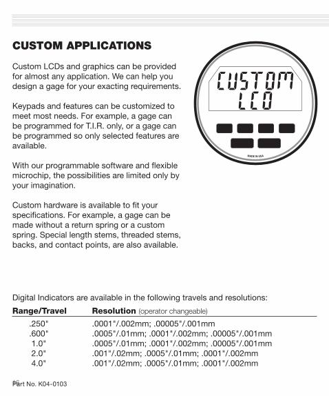
CUSTOM APPLICATIONS
Custom LCDs and graphics can be provided for almost any application. We can help you design a gage for your exacting requirements.
Keypads and features can be customized to meet most needs. For example, a gage can be programmed for T.I.R. only, or a gage can be programmed so only selected features are available.
With our programmable software and flexible microchip, the possibilities are limited only by your imagination.
Custom hardware is available to fit your specifications. For example, a gage can be made without a return spring or a custom spring. Special length stems, threaded stems, backs, and contact points, are also available.
Digital Indicators are available in the following travels and resolutions:
Range/Travel Resolution (operator changeable)
.250" .0001"/.002mm; .00005"/.001mm .600" .0005"/.01mm; .0001"/.002mm; .00005"/.001mm 1.0" .0005"/.01mm; .0001"/.002mm; .00005"/.001mm 2.0" .001"/.02mm; .0005"/.01mm; .0001"/.002mm 4.0" .001"/.02mm; .0005"/.01mm; .0001"/.002mm
MADE IN USA
Part No. K04-0103


![Operating instructions Analytical balance 80-4N... · 10.7.1 Freely programmable weighing unit ... 400 mA 50/60Hz . ... With numerical input the indicator [#] appears](https://img.dokumen.tips/doc/110x75/5aaf50c67f8b9a3a038d3554/operating-instructions-analytical-balance-80-4n1071-freely-programmable-weighing.jpg)