Embed Size (px)
Citation preview

Pesticides Research Nr. 59 2002Bekæmpelsesmiddelforskning fra Miljøstyrelsen
Autonomous weeders for Christmastree plantations - a feasibility study
Henrik Have (Editor)
With contributions from:
Simon Blackmore1 Henrik Have1, Bent Keller2, Spyros Fountas1,Henning Nielsen1 and Frans Theilby2
1) The Royal Veterinary and Agricultural University, Section ofAgroTechnology2) The Danish Forest and Landscape Institute, Department ofForestry

The Danish Environmental Protection Agency will, when opportunity
offers, publish reports and contributions relating to environmental
research and development projects financed via the Danish EPA.
Please note that publication does not signify that the contents of the
reports necessarily reflect the views of the Danish EPA.
The reports are, however, published because the Danish EPA finds that
the studies represent a valuable contribution to the debate on
environmental policy in Denmark.

3
Contents
PREFACE 5
SAMMENFATNING 6
SUMMARY 8
1 INTRODUCTION 10
2 THE ECONOMIC SIGNIFICANCE OF CHRISTMAS TREEPRODUCTION 12
2.1 STRUCTURE 122.2 EXPORT 122.3 ECONOMICS 12
3 CURRENT CULTIVATION METHODS 13
3.1 ESTABLISHMENT 133.2 WEED CONTROL METHODS 14
3.2.1 Chemical 143.2.2 Mechanical 14
3.2.2.1 Conditions for mechanical weeding 163.2.2.2 Tools for mechanical weeding 17
3.2.3 Animals 193.3 HARVESTING 193.4 CONTRACTORS AND CONTRACTOR COSTS 193.5 COSTS OF THE VARIOUS OPERATIONS 19
4 WEED CONTROL REQUIREMENTS IN CHRISTMAS TREEPRODUCTION 21
4.1 METHOD 214.2 RESULTS 22
4.2.1 The average height of the trees. 224.2.2 Root collar diameter of the trees 234.2.3 Health score of the living trees. 234.2.4 Soil moisture 24
4.2.4.1 Tønballegård 244.2.4.2 Wedellsborg 25
4.3 OTHER INVESTIGATIONS 264.4 DISCUSSION 264.5 SUB CONCLUSION 27
5 SPECIFICATION OF STAKEHOLDER REQUIREMENTS 28
5.1 THE CURRENT LEVEL OF SATISFACTION WITH SPRAYING ANDMECHANICAL WEEDING TECHNOLOGY 285.2 STAKEHOLDER REQUIREMENTS TO AN ACW 295.3 SUB CONCLUSION 30
6 SPECIFICATION OF TECHNICAL REQUIREMENTS FOR ANAUTONOMOUS CHRISTMAS TREE WEEDER 31
6.1 OVERVIEW OF CULTIVATION METHODOLOGY 31

4
6.2 DEFINITION OF OPERATION SCENARIOS FOR THE ACWDEVELOPMENT 326.3 DEFINITION OF WORK TASKS 326.4 SUB CONCLUSION 33
7 AUTONOMOUS VEHICLE TECHNOLOGY – A LITERATUREREVIEW 34
7.1 AUTOMATIC AND AUTONOMOUS VEHICLES IN AGRICULTURE,FORESTRY AND HORTICULTURE 357.2 EVOLUTION OF AUTOMATIC STEERING FOR AGRICULTURALVEHICLE 367.3 SENSORS FOR NAVIGATION 37
7.3.1 Real time Kinematic global position system 377.3.2 Computer vision 377.3.3 Supplementary sensors 387.3.4 The leader-cable principle 387.3.5 Laser-based principles 387.3.6 Other principles 39
7.4 SAFETY 397.5 SYSTEMS ARCHITECTURE 40
7.5.1 Three-layer architecture 417.5.2 The Saphira architecture 417.5.3 The animate agent architecture 427.5.4 Behavioural reactive system architecture 42
7.6 SUB CONCLUSION 42
8 PROPOSED OUTLINE OF AN AUTONOMOUS CHRISTMASTREE WEEDER 44
8.1 WEEDER TOOL 448.2 OPTIMUM OPERATION PATTERN AND VEHICLE POSITIONING 448.3 VEHICLE CONCEPTS 45
8.3.1 The beetle type 458.3.2 The portal type 47
8.4 VEHICLE OPERATION PROCEDURE AND TRANSPORT 478.5 SYSTEM ARCHITECTURE 488.6 SUB CONCLUSION 48
9 ESTIMATED PERFORMANCE OF SELECTED ROBOTCONCEPTS 49
9.1 ENVIRONMENTAL BENEFITS 499.2 EFFECTIVENESS OF WEED CONTROL 499.3 MACHINE CAUSED LOSSES 499.4 SAFETY 509.5 ESTIMATED AREA CAPACITY 509.6 ESTIMATED COSTS 519.7 ADDED VALUES 549.10 SUB CONCLUSIONS 54
10 CONCLUSIONS 55
11 REFERENCES 57
Bilag A: A specification of behavioural requirements for an autonomoustractorBilag B: Proposed Systems architectureBilag C: General motivation of using autonomous vehicle systems.

5
Preface
Agriculture, horticulture and forestry have in the past benefited from asuccession of technological developments that have brought greaterproductivity and economic efficiency. Historically, the emphasis of thesedevelopments has been on the mechanisation to increase work rates throughuse of larger and more powerful machines. The newer information basedtechnologies have already been used for some time to improve functions andcontrols of machinery, especially for spatial graduation of treatments. Thesetechnologies have now reached a stage which seems to make autonomous fieldmachinery and individual treatment of plants realistic.
Mechanical weeding in Christmas tree plantations is a well suited area tobegin development of such equipment because of the relatively large size ofthe plants, the difficulties of using standard agricultural machinery andpresent extensive use of herbicides.
This report presents results from a study on the feasibility of developing anautonomous Christmas tree weeder, including the technical, economic andenvironmental aspects, as well as the possibilities of using it for automatic datacollection for management decisions.
The study was carried out in a collaborative project between The RoyalVeterinary and Agricultural University, Section for AgroTechnology and TheResearch Centre of Forestry and Landscape, Department of ForestManagement. The study has been financially financed by the Ministry ofEnergy and Environment.
I acknowledge with thanks the valuable assistance we have received from:Tomas Nordfjell, The Research Centre of Forestry and Landscape,Hans-Werner Griepentrog, The Royal Veterinary and Agricultural UniversityBent K. Christensen, The Christmas Tree Growers Association,Sten Gellerstedt, Forestry Robot Research Group, Agricultural UniversitySweden,Andreas Bergstedt, The Royal Veterinary and Agricultural University,Mogens Blanke, The Technical University of DenmarkSøren Honoré, Danish Forest and Nature Agency,Esben Pedersen, Silvatec A/S, andMorten Sørensen, Wedellsborg Estate.
Dvoralai Wulfsohn has checked the language.
Henrik Have

6
Sammenfatning
Den danske juletræsproduktionen dækker ca. 31000 ha og har en samletomsætning på 500-600 mill. kr. Omkring 4100 producenter er involveret. Defleste har mindre end 1 ha.
For at opnå god vækst og kvalitet af juletræer er det nødvendigt med hyppigukrudtsbekæmpelse. Dette gennemføres i langt de fleste tilfælde medherbicider, hvilket fører til helt rene kulturer med ringe levemuligheder forandre arter. Endvidere medfører det risiko for forurening af grundvandet.
For at reducere disse problemer er der udviklet maskiner til mekaniskrenholdelse. De første ca. 2 år efter plantningen kan anvendes såkaldtelangfingerharver, der kan bekæmpe mindre ukrudt uden at beskadige træernefor meget. I de efterfølgende vækststadier er det nødvendigt at anvenderadrensere eller andre tilsvarende maskiner. Disse maskiner er imidlertid fordet meste kun i stand til at bearbejder jorden mellem rækkerne. Bekæmpelsener således mindre effektiv. Samtidig er omkostningerne omkring dobbelt såhøje som for sprøjtning. Endvidere har jordbearbejdningen uhensigtsmæssigevirkninger i form af udvaskningen af næringsstoffer og øget jorderosion.
Nærværende projekt præsentere muligheder og ideer for udvikling af en lilleautonom maskine til mekaniske ukrudtsbekæmpelsen på en mere miljøvenligmåde. Studiet er indledt med en undersøgelse af det minimale behov forukrudtsbekæmpelse på basis af løbende forsøg ved Forskningscenter for Skovog Landskab. Den viste, at det er tilstrækkeligt at bekæmpe ukrudtet i cirkleraf 40 cm radius omkring det enkelte træ, hvilket svarer til ca. 40% af det totaleareal. Det ikke bekæmpede ukrudt på den øvrige del af arealet må gerne blivestående, da det giver en vis læ og derfor har en positiv virkning på væksten aftræerne.
På basis af et litteraturstudium vedrørende robotteknologi er der i projektetudarbejdet konceptforslag til nogle forskellige systemer, herunderoperationsmønstre, design af køretøj, behov for sensorsystemer, databaser ognavigationssystem. Også et estimat for omkostningerne ved brug af en sådanmaskine er blevet udarbejdet for at kunne sammenligne medmaskinstationstakster for nuværende operationer.
Undersøgelsen konkluderer, at det ud fra et tekniske synspunkt er realistisk atudvikle en sådan lugemaskine, og at den vil kunne opfylde målsætningen omat renholde arealet omkring træerne og at lade det meste af floraen stå.Endvidere konkluderes det at maskinen for små omkostninger vil kunneudvikles til i forbindelse med arbejdet, at indsamle data om det enkelte trævedrørende tilstand og kvalitet med henblik på anvendelse i driftsledelsensbeslutningstagning og dokumentation.
Det vurderes, at maskinen vil have væsentlige lavere miljømæssige effekter oggive en lidt bedre tilvækst end de nuværende teknologier (sprøjtning ogmekanisk ukrudtsbekæmpelse). Det vurderes endvidere, at maskinkonceptetvil have betydelig interesse i forbindelse med ukrudtsbekæmpelse i andrespecialkulturer, som f.eks. frugt- og bærplantager.

7
Det valgte koncept bygger på nøjagtig bestemmelse af positionerne for deenkelte træer og for den autonome maskine ved hjælp af et meget præcistglobal positioneringssystem (RTK GPS). Træernes position tænkes målt ogkortlagt automatisk i forbindelse med plantningen, idet et elektronisk systemmåler positionen, hvor de placeres i jorden. Det fremkomne kort anvendesderpå gennem hele plantagens levetid af den autonome maskinen somgrundlag for navigation under arbejdet. Ud over positionen vil der også værebehov for løbende måling af en række andre parametre for tilstanden omkringog på maskinen til brug for navigation, styring og kontrol, herunder etintegreret sikkerhedssystem, der skal forhindre sammenstød medforhindringer, beskadigelse af træer og materiel, samt tilskadekomst afmennesker og dyr. Disse styrings - og kontrolfunktioner er struktureret i ensærlig systemarkitektur.
Til bekæmpelse af ukrudtet er valgt en rotorklipper, der har mindreenergiforbrug og næsten lige så god effekt som et jordbearbejdningsværktøj.Som operationsmønster er valgt en tilnærmelsesvis retlinet bevægelse langsden enkelt række, hvilket har vist sig at være det mest effektive og økonomiske.Det er endvidere valgt, at styre rotorklipperens horisontale finpositionering iforhold til det enkelte træ via en mekanisk eller optisk sensor.
To typer af platforme er undersøgt: 1) En lille, lav 4 hjulet maskine, der kankøre under grenene og ind mellem træerne, og 2) En portal maskine, der kan”skræve” over en række og bearbejde på begge sider. Den førstnævnte typevurderes at være den enkleste og mest velegnede.
Det er valgt at opbygge systemarkitekturen i flere lag, der bl.a. omfatter”koordinatoren”, som er det menneske, der sætter maskinen i gang og løbendeer i kontakt med maskinen via en PC, ”vejlederen”, der er en computer påmaskinen, som primært via ”mode changer” sørger for at maskinen opførersig hensigtsmæssigt (navigation, ruteplanlægning, sikkerhedscheck ogudførelse af arbejdsopgaver mm.), sekundært vejleder de forskellige stadier afmaskinens sikkerhedsadfærd og endelig kommunikerer maskinens situationeller tilstand til koordinatoren.
Med hensyn til omkostningerne ved anvendelsen af maskinen må der i deførste tid efter udviklingen forventes et noget højere niveau end for de kendteteknologier. Men den generelle udvikling i elektroniske komponenter ogudstyr, sammen med stigende produktionstal må forventes ret hurtigt atbringe omkostninger ned på et niveau mellem de nuværende mekaniske ogkemiske metoder. Ud over dette vil maskinen antagelig kunne givetillægsværdier i form af indsamlede data for det enkelte træ som grundlag fortil driftslederens beslutninger og kundeinformation.

8
Summary
The Danish Christmas trees production covers about 31000 ha and has anannual turnover about 500-600 million DKK. About 4100 producers own thisarea. The majority have less than 1 ha.
To obtain good growth and quality frequent weed control is essential. This ismainly done by application of chemicals, which leads to clean stands withpoor living conditions for other species and risks of pesticide leaching.
To reduce these problems of chemical weed control machinery has beendeveloped for mechanical weeding. The first approximately two years afterplanting it is possible to use special spring tooth harrows with long flexibletines, which are effective in control of small weed plants without damaging thetrees too much. In the following growth phases it is necessary to use row cropweeders. These weeders, however, are generally only able to control weedsbetween the rows an also less effective and more costly to use than herbicides.In addition the tillage process may cause negative effects of nutrient leachingand soil erosion.
This project report presents the feasibility of developing a small autonomousmachine for mechanical weed control in a more environmentally friendly way.The study was initiated by defining the minimum requirements to weedingusing results from an ongoing investigation at The Danish Forestry andLandscape Research Institute. This investigation has shown, that maximumtree growth and development is achieved by weeding of concentric circle areasof only 40 cm radius around each tree. The left over weeds on the remainingarea have beneficial effects on the trees because of shelter effects.
On the basis of a literature review the idea and overall concepts of a smallautonomous weeding machines is outlined, including suggestions of operationpatterns, physical designs of the vehicle and the system architecture withsensors, databases, navigation system, and actuators. Also the likely costs ofusing such a machine were estimated and compared to currents contractorrates.
The study has led to the conclusion, that it from a technical point of view isrealistic to develop an autonomous Christmas tree weeder and possible tofulfil the aim of cleaning only part of the area. In addition the machine isconsidered suitable for collection of tree specific data concerning conditionand development for use in plantation management and productdocumentation.
It is estimated that the machine will have significantly lower environmentaleffects and facilitate better tree growth than present technologies (sprayingand mechanical weeding). Further on it is estimated, that the machine asconcept will have considerable interest for weed control in other specialcultures as fruit and berry plantations.
The chosen concept is based on centimetre precision determination of theposition of each tree as well as the current position of the ACW by means of a

9
RTH GPS (Real Time Cinematic Global Positioning System). The positionsof the trees are to be measures automatically during machine planting byrecording of the position where the tree is placed in the soil. The mapproduced in this way can then be used by the autonomous machine as basisfor navigation during weeding over the entire lifetime of the plantation. Apartfrom the position it would also be necessary to measure a number of otherparameters of the conditions around and in the machine itself for navigation,steering and controls, including an integrated safety system, which is to avoidcollisions with obstructions, and injury of humans, animals and trees. Thesesteering and control functions are structurized in the system architecture.
As weed control tool is chosen a rotor cutter similar to those used in certainlawn mowers, as this needs less energy than tillage, and the effect is nearly thesame as for mechanical weeding. As operation pattern is chosen a nearly linearmovement along the rows as this was found to be the most economic. It wassuggested to control the horizontal fine position of the rotor relative to thesingle tree by means of an optical or mechanical distance sensor.
Two platforms were considered: 1) A small, low machine being able to movebelow the branches and in between the trees. 2) A portal machine that have aset of wheels and a working tool on either side of the row. The first isestimated to be the simplest and best suited.
The system architecture, which is to be built up in several layers, comprises acoordinator, who is the person that runs the vehicle via a PC, a supervisor,which is a computer, that primarily via a ”mode changer” controls themachine to behave appropriate, i.e. to navigate, to do route planning, safetycheck, and secondary supervision at the different stages of the safetybehaviour, as well as communicating the situation and conditions to thecoordinator.
As regards economy it is estimated that the continued price reductions ofelectronic equipment together with increasing production numbers ratherquickly will bring the costs dawn at a level between the present costs ofmechanical weeding and spraying. On top of that added values may beachieved in terms of tree specific data for management decisions andcostumer information.

10
1 Introduction
To achieve good growth and quality of Christmas trees it is traditionallyconsidered necessary to weed very intensively to compensate for the weakcompetitiveness of Christmas trees, especially Nordmann’s fir, which is themost grown species. Intensive weed control is in most cases achieved byapplication of persistent soil herbicides with a broad spectrum of effect.
In resent years many growers have shifted to screened spraying with foliageacting herbicides. The rate of application is usually close to the allowedmaximum, and the spraying takes place every year over the entire productionperiod (app. 10-12 year).
The extensive use of herbicides is alarming in itself, especially seen in the lightof the latest investigations, which show that it is leaching into the soil(Jacobsen et al. 2000). Leaching of nutrients – especially nitrates – from a soilalmost without vegetation is also considerable, as the sparsely placed trees areonly able to utilise an insignificant fraction (Rubow et al. 2000). Thebiodiversity of total cleaned areas is probably very low as a result of the lack offood and hiding places.
This makes Christmas tree plantations a high priority area for alternativeweeding methods (Bichel, 1998). Some growers have moved in that directionduring the past years and are beginning to use mechanical weeding (Keller,1997). The weeding implements developed for the purpose are well able toremove weeds between the rows, but mostly not in the rows, where the need isgreatest. Most of the implements are rather heavy, of low capacity, and costlyto use. The general strategy of weeding using these machines is the same asfor spraying: to achieve a total clean area. Therefore, this also leads toproblems of leaching and relatively low biodiversity.
The purpose of the present project was to investigate the feasibility ofdeveloping a light, autonomous weeding machine being able to performmechanical weed control more competitively within a relatively short period oftime and also to reduce the environmental problems associated with thepresent methods. The machine should have an acceptable behaviour, be ableto operate unattended and safely for longer periods of time.
The project comprises: a description of the present Christmas tree cultivation systems, an investigation of the need for weed control around single Christmas
trees, specification of the conditions in which the autonomous systems should
work, specification of the stakeholder requirements of an autonomous system, specification of the technical requirements of the system two proposed machine concepts, a proposal for a system architecture, including navigation system, safety
system and overall control system, an evaluation of the proposed concepts compared to present methods,
including biological, technical, economic, environmental and safety issues

11
as well as the possibility to achieve added values by collection ofinformation on the trees for management decisions.

12
2 The economic significance ofChristmas tree production
Bent KellerThe Danish Forest and Landscape Institute, Department of Forestry
According to the registrations at The Production Fee for Christmas Trees andGreenery (PAF) that the production area in Denmark is 31.370 hectare.From this Nordmann’s fir constitutes the major part (approx. 22.000 hectare)and noble fir approximately 9.000 hectare. Further there are some specialproductions of cypress, Serbian spruce, holly, cryptermeria and others. Andfinally there is Norway spruce, which is either produced in field plantations ortaken from forest plantations as thinning trees. The total area is thus app.35.000 hectare.
2.1 Structure
About 4.100 producers are registered, of which the majority are operatingwith area units < 1 hectare. It is estimated that the size of an averageproduction unit is about 1,5 hectare; however, there has been a tendencytowards larger production units during the later years.
2.2 Export
Denmark is the country in Europe that exports the most Christmas trees andgreenery cuttings. Each year 6-8 million Christmas trees and 30 – 35.000tonnes of greenery cuttings are exported. The major buyer is Germany with50 – 60% of the Christmas trees and 70 – 75% of the greenery cuttings. Nextin place are France, Austria, England, Switzerland and Norway.
2.3 Economics
The annual turnover is 500-600 million DKK and makes up 50% of the totalturnover of Danish forestry. For each producer this involves a very intensiveproduction in which about 100.000 DKK per hectare is tied up in one cropfor a period of 10 years. An essential condition for a reasonable yield of theinvestment is that the plantation is weeded. Today this is to a great extent(app. 70% of the area) done chemically, amounting to 20-25% of the totalcultivation costs equivalent to around 25.000 DKK per hectare.

13
3 Current cultivation methods
Bent KellerThe Danish Forest and Landscape Institute, Department of Forestry
This chapter provide an introduction to the most common methods ofChristmas tree production in Denmark with focus on mechanical weeding.Other control methods are described briefly.
3.1 Establishment
At present Christmas tree plantations are established on considerable areas.The majority of the plantations are established on previously cultivated land,and only a small part on forestland. When establishing plantations the area isin most cases prepared with thorough brushwood clearing and stumping,sometimes followed with several haulages with a spring tine harrow to removeirregularities. The area is on the whole ready to be treated like previouslycultivated land.
Today three cultivation methods are used:
1. Clear cutting (planting - harvesting of all trees – planting). This isthe most prevalent cultivation system. It is highly systematic and iseasy to manage regarding planning. The planting is generally donewith planters. The planting distance is typically 1,2 x 1,2 m, equal toapp. 6.000 plants per hectare (Figure 3.1).
2. Current planting (planting every time a tree is cut). Planning within
this cultivation system is much more difficult because the trees in eacharea are of different ages and thus have different demands regardingtreatment. However this system gives a more even division of expensesand income. Here planting is always carried out manually. Themethod has some biological as well as environmental advantages.
3. Regeneration (new trees develop from the stumps of the cut trees).
This method is only used to some extent because it is technicallydifficult, hard to manage, and often gives a poorer quality. Theadvantages are that there are no planting expenses, and as the plantalready is established there will be no period of stagnation ofestablishment.

14
Figure 3.1. Normann´s firs planted in rows.
3.2 Weed control methods
There are advantages as well as disadvantages to the presence of weeds in thecultivation area.
Advantages:• Leaching of nutrients is diminished• Microclimate is improved• Risk of wind- and water erosion is diminished• The biodiversity is improved
Disadvantages:• Increased competition for water, light and nutrients• Physical damage such as wear on the trees• Grass vegetation increases the risk of spring night frost damage• Complicates trafficking
Normally the disadvantages are rated to carry great weight and this is why avery intensive weeding is started. This weeding can be chemical, mechanicalor using animals.
3.2.1 Chemical
Chemical weeding is by far the most used weeding method. Traditionallyslowly degradable broad-spectrum soil weed control was used. The rate ofapplication was always close to or the maximum allowed dose, and theapplication was repeated each year throughout the rotation, which was 10-12years. Several of the traditionally used persistent soil weed controls are noweither forbidden or are being re-evaluated, and many of the producers havenow started using screened spraying with leaf spray. The purpose of weedingis still the same – to keep the cultivation totally or almost free weeds.
3.2.2 Mechanical
Mechanical weeding of Christmas trees is the method that at present is

15
regarded to be the best alternative to chemical weeding. Mechanical weedingin plantations on previous forestland demands careful brush wood clearingand either stump removal or stumping, as the available tools have beenproduced for cultivated land without obstacles in the soil.
Mechanical weed control can be done by mowing plants above the ground orby soil tillage. Soil tillage is superior and the safest method. Mowing does notreduce the risk of spring night frost like soil tillage, and the competition fromthe weeds for water will not be completely reduced. A high occurrence ofnatural vegetation has a beneficial effect however, during winter as it reducesthe risk of winter frost damage, and a certain competition from the vegetationcan probably have a beneficial restrictive effect on leader shoot growth.Therefore mowing can sometimes be justified, for example combined withother weed control methods (sheep grazing) and at certain times in therotation or growth season. The following descriptions focus on soil tillagemethods only.
The weed controlling effect of soil tillage consists of detaching and covering ofthe weed. The effect of this depends on a number of factors: among othersthe weather, the soil structure and moisture, the structure of the weed and thestage of development of the weed, travelling speed and depth of tillage. Theeffect is very dependent on the weather and can be considerably reduced inmoist weather and soil. The effect is highest when the weed control is carriedout in a dry period, as the detached weed will dry more rapidly. In moistweather the weed will often strike roots and keep on growing. Most toolsoperate better in sandy soil than in heavy clay soil, where the effect can bevery poor. Furthermore moist clay soil is restricted to drier periods. Rootweeds are difficult to control mechanically, whereas seed weed is easy tocontrol. The majority of the tools known today have not sufficient effect onstrong and well-developed weeds, but are effective against smaller weeds. Formany tools the effect is better speeds of 8-12 km/h than at 4-6 km/h, however,it can be difficult to drive at high speed without damaging the trees if the treeshave not been planted correctly at equal distances. The depth of soil tillagehas great influence on the effect on root weeds and larger seed weeds; deepsoil tillage can damage tree roots.
To obtain a satisfactory result with mechanical weeding it is thereforeimportant to weed frequently, while the weeds are still small. One should notclean but keep clean. Blind harrowing – before the weeds starts to grow –often gives extremely satisfactory results. However, early actions can behindered by moist soil, which is not suitable for traffic and tillage. The weedsstart to grow in April and grow tremendously from May and onwards. Sincethe risk of tools damaging the newly busted buds is large, it is advisable not todrive in the plantations for 2-3 weeks in the period of bud breaking. It istherefore essential to weed before bud breaking. Depending on thecircumstances the treatments have to be repeated 4-8 times per growingseason.
Only very few tools have the capacity to clean in the actual rows (spring tineharrow, hydraulic Dutch hoe, rotor harrow on flexible arm), most tools areonly able to weed in the inter-row area. In that case weeds are left around thetrees, where competition for water for the first 2-3 years probably is mostintensive. When the tree crown has grown bigger and denser the competitionfor water will be most intensive in the periphery of the crown. The trees areby now shading away the majority of weeds near the stem, nevertheless there

16
will still be competition for light, and wear on the branches by tall weedspresent in the row.
3.2.2.1 Conditions for mechanical weedingThe planning is one of the most important conditions for a successfulmechanical weeding. The whole sequence of the cultivation has to bethoroughly considered and carefully planned. Firstly to make sure that theweeding practically can be carried out with the tools and machines at disposal,and secondly to ensure as low weeding costs as possible
Row length. It is crucial for the achievement and with this the economy ofmechanical weeding, that the rows are as long as possible to minimise thenumber of turnings.
Appropriate headland. It is important that the rows do not continue all theway out to any fence around the plantation. A headland sufficiently broad forthe later operating machines and tools is necessary. If the headland is toonarrow the operator of the machine is forced to go forward and backwards tobring the machine in position.
Irregular areas. Irregular areas should as far as possible be avoided or beadjusted, as wedge-shaped areas with the direction of row taperingproportional to the headland are time-consuming and space demanding toweed. It is comparatively time-consuming to turn and bring tractor and tool inposition. The headland, which is an unproductive but indispensable area,must also be considerably wider for the tractor and tool to make turns.
Distance between the rows. The distance between the rows must match thetools and machines to be used. It almost seems commonplace to mention this,but it is very often seen that the plan of cultivation had to be rearrangedbecause the distance between the rows appeared not to fit to the machines atdisposal.
Straight parallel rows. To carry out mechanical weeding at a sufficiently highspeed the rows should be straight and parallel, at least in sets corresponding tothe width of the weeding implement. Sufficiently accurate planting can beobtained either by a planting machine with a number of rows which fit thesubsequent tools, or by drilling the area with a suitable number of holes beforethe plants are manually planted. Manual planting after two or more sticksdoes not give a satisfactory result.
The size of the weed. In general only a small number of the tools on themarket right now can manage taller weed. The tools normally operatesatisfactory on weed sizes up to 5 cm. If the weeds get much higher they maycause implement clogging or get entangled.
Soil conditions. Mechanical weeding is most successful and easy on light soil.The heavier the soil the harder mechanical weeding is to perform. On verystiff clay soils the traffic conditions in wet or moist periods can be so difficult,as to exclude the possibility of mechanical weeding.
The weather. The ideal weather for mechanical weeding is warm, dry and alittle windy. The detached weed dries quickly and does not strike roots again.In practise it is not always possible to wait until the weather is ideal because ofthe risk tat the weeds will grow too high. Therefore weeding is often carried

17
out on wet soil and in weather conditions. This means that a lot of weedsstrikes roots and keep on growing. Even though the weeds are not controlledthey are impeded and will not get so high that the tools can no longer manage.
3.2.2.2 Tools for mechanical weedingSeveral types of soil tillage tools are used in Christmas trees. These aredescribed below.
Spring tine harrow. This is one of the few tools able to weed in the rows.However, as it worksng in full width and thus running over the trees, the useof it is limited to the second and in rare cases to the third year after planting.Then the trees have become too high and will be damaged. In some caseswhere the spring tine harrow has been used, damage as found to on theunderside of the branch on the lowest branch whorl from the second or thirdgrowth year. However the survival and the growth of the trees does not seemto be influenced considerably neither in the short nor the long term. There is aparticularly great risk of damage when using the spring tine harrow duringand just after bud breaking. The tool works best on sandy to medium heavysand, whereas the effect on heavy clay soil is poor. On sandy soil the toolworks best on dry soil. On clay soil the effect is normally best on moist soil. Byregulation the weight of the harrow e.g. by means of hydraulics, the effect canbe increased even on dry clay soil. The harrowing depth can also be adjustedto fit to soil, weed and so on.
The effectiveness of the tool is due to covering of the weed plants. This meansthat the impact is highest on little seed weeds from the stage of seed leaf andup to 5 cm height. The spring tine harrow has poor influence on larger seedand root weeds. If the spring tine harrow is the only tool used for weeding inthe first 2-3 years, there is risk of extensive couch grass development.
As the spring tine harrow works independently of rows, there are no demandsas to accuracy when planting. However as the tool has a highly reduced effecton weeds higher than 5 cm it is necessary to carry out 5-8 haulages perseason.
The spring tine harrow has many advantages on lighter soils:• it works in the full width and is thus weeding in the rows close to the
trees,• it has a wide working width and therefore a high field capacity,• it is easy to manage and suitable for fast driving, because it is not
necessary to drive accurately in relation to the rows,• it does not demand specific distances between the rows.
However the spring tine harrow also has some distinct limitations:• the suitability on heavy soil is limited,• it can only be used in quite young cultivation, as explained above.
Disc harrow or spade-roller harrow. The Lindenborg harrow, which is a discharrow, is usual in forestry for soil tillage. It has a good effect on seed as wellas root weeds. The tool leaves comparatively broad unprepared streaksaround the trees, and sometimes it causes problems with banks or soil thrownat the planted trees.The Loft spade-roller harrow runs over every second row and weeds in thetwo row spacing. High weed can get entangled in the spade rollers, whichthen cannot work freely. To avoid one-sided moving of soil and banking the

18
spade rollers are placed on two axles working towards each other. The effectof the harrow depends on the travelling speed. It takes quite some speed – 12km/h or more – to obtain a satisfactory effect.
Hoe. A hoe is a tool that follows the rows. The working organs can havedifferent shape, but the most common is tines with one- or two-wingedshares. If mounting half shares towards the row the roots of the trees will bespared damages. The tool undercuts and covers the weed; the most importanteffect is the undercutting. The tool controls weed efficiently; the hoe normallyeven has an effect on root weeds – e.g. couch grass . Due to the aggressiveundercutting it has a good effect on higher weed, and is much less dependenton the size of the weed than the spring tine harrow. At any rate this alsoconcerns the hoe the less weed the easier the control. The hoe can be usedthroughout the rotation. Only the height of trees compared to the tool bearer’sfree height reduces its utility. The decisive disadvantage of hoe, is that it canonly weed in the spacing between the rows and not in the actual rows.
The conditions of success with this type of tool:• that the rigidity of the tines fits the type of soil,• that the winged shares give full cutting of the soil and have a good
overlap,• that the tines, to give the highest possible material flow, are placed
with large distance• that the tines do not go deeper than app. 5 cm, often even higher,• that the travelling speed is at least 5 to 6 km/h, so that the tines are
vibrating, keeping themselves cleaned, and bringing the cut off ordetached weed to the ground surface.
Hydraulic Dutch hoe. The hydraulic Dutch hoe can be used for weeding inthe actual rows. A hydraulic run knife of 50-65 cm undercuts the weed at thedepth of 2-5 cm. The tool is mounted with a mechanically or ultrasonic sensorthat disconnect the hydraulic system when it senses some resistance – e.g. thestem of a tree. As the tool is driven forward due to the resistance from thesoil, the knife is pushed back and turns out into the space between the rows.After the tree has been passed the knife is then again hydraulically activatedinto the row. Hydraulic Dutch hoes are used in ecological as well asconventional fruit plantations. In the fruit plantations 7-8 haulages per seasonare needed to achieve sufficient effect. The travelling speed is 7-10 km/h.
Rotary cultivator. The rotary cultivator is also an option. The knives aremounted on a horizontal-rotating axle. The rotary cultivator works by tearingup, cutting up and covering. The effect on weeds is good, and the rotarycultivator can handle even large amounts of weeds and thick grass. Rootweeds, however, can only be controlled with repeated treatments. The rotarycultivator can be problematic to use for repeated haulages in the cultivationdue to the risk of damaging the soil structure. The rotary cultivator is onlyweeding in the space between the rows. The PTO run rotary cultivator has alow performance, whereas the friction driven rotary cultivator has a highperformance.
Under the category of rotary cultivators also belongs the hydraulic drivencultivator from the firm PolyTrac Inc. – the so-called “Mulcher”. TheMulcher can tear up and break even high weed without getting entangled.
Rotary harrow. The rotary harrow has vertical stiff tine rotors that has a

19
cycloidal movement through the soil. This levels the soil fairly well across thedirection of travel. The firm of Silvatec produces a PTO driven rotary harrowintended for weed control in Christmas tree plantations. The rotary harrow isalso available mounted on a flexible arm, which makes it possible to weed inthe actual rows between trees big enough to reject the tool. The rotary harrowis suitable for weeding in overgrown cultivations.
3.2.3 Animals
Together with mechanical weeding grazing is among one of the mostpromising methods of weed control in Christmas tree cultivations at themoment. In principle grazing can be carried out with many different speciesof grazing animals; however, sheep of improved fattening breeds – especiallyShropshire – are the most used.
3.3 Harvesting
The harvest of Christmas Trees starts in the early autumn with classificationand marking every tree. In the middle of November the actual harvestingstarts. Felling is accomplished using handsaws, brush cutters or chain saws.During the past years there has been a development within mechanic fellingmachines. After felling the trees are dragged or carried out manually to thetractor tracks in the cultivation, where the trees are wrapped to protect themand facilitate further transportation to a central loading place easier. The treesare then loaded on lorries. Over the past years there has been a developmentof more mechanized transport systems, where the trees after wrapping areplaced on pallets, which makes the further transport considerably easier.
3.4 Contractors and contractor costs
The use of contractors has become more common within Christmas treecultivations. This is partly because of the general reduction of the permanentstaff within the trade, and partly because the individual Christmas treeproducer gets the work done by experts having special machines at theirdisposal; machines that would not be economical for the individual Christmastree producers to own. The contractor can today carry out all the tasks withinChristmas tree cultivation, from little isolated jobs to turnkey contracts.
It is difficult to get an exact overview of the contractor costs, as these arestrongly dependent on the conditions. Some contractors operate with a fixedrate per hour and a special road rate. Others have fixed prices per hectare withextra charges for small or difficult jobs/areas. Others again are not paid perhour or hectare but work out an offer for each contract
On good areas without road transport the contractor costs for mechanicalweeding with a tractor mounted harrow are estimated to be between 2.200 to3.000 DKK/ hectare/year at a price per hour of about 400 DKK weeding withrotary cultivator/mulcher mounted at a special tool carriers will amount from1.250 to 2.850 DKK/hectare/year at a price per hour of about 475 DKK.depending on the planting and weeding system.
3.5 Costs of the various operations
In table 3.1 is shown a typical cultivation model for 1 hectare of Nordmann’sfir Christmas tree cultivation on former farmland. Planting is assumed to be

20
carried out manually, and spraying with leaf and soil herbicides is used forweed control.
Table 3.1. Estimated cultivation costs (DKK/hectare).Year from establishing 0 1 2 3 4 5 6 7 8 9 10 11 TotalCosts, DKKPreparing chemical weeding 907 907Soil preparation 1.155 1.155Plants 13.889 1.389 15.278Planting including transportation 5.884 833 6.717Fence 8.716 2.309 11.025Chemical weeding 1.245 1.991 3.581 1.991 3.581 1.991 3.581 1.991 2.336 779 779 23.846Insect control 679 679 679 679 679 679 679 4.753Fertilisation 771 826 892 892 892 892 892 6.057Pruning 200 500 1.000 1.000 1.000 1.000 1.000 5.700Various 600 600 600 600 600 600 600 1.200 1.200 1.200 1.200 1.200 10.200Cultivation costs total 32.396 4.813 4.381 2.591 5.452 4.096 6.752 5.762 6.107 4.550 4.550 4.188 85.638

21
4 Weed control requirements inChristmas tree Production
Bent KellerThe Danish Forest and Landscape Institute, Department of Forestry
This chapter present results from an ongoing experiment that has the purposeof investigating the influence of different spatial weeding intensity onChristmas tree growth and survival on former agricultural land.
4.1 Method
The species in the experiment are Nordmann fir (Abies nordmanniana). Twoparallel test areas were established; one in Randbøl National Forest District –at Tønballegård, and one in Wedellsborg Forest District. The experimentalarea at Tønballegård is on a clay loam soil and the area at Wedellsborg is on alight sandy soil. Planting was done with machines. Around each tree a circle isweeded mechanically.
The following treatments are included in the test (the percentage area iscalculated on the basis of a planting distance, which leaves a circular growthspace of app. 1.2 m2 for each tree. The actual planting distance in the trial iswider):
1. 0% (un-weeded)2. 20% (mechanically weeded, r=28 cm or 0.25m2)3. 40% (mechanically weeded, r=39 cm or 0.48 m2)4. 60% (mechanically weeded, r=48 cm or 0.72m2)5. 80% (mechanically weeded, r=56 cm or 0.99 m2)6. 100% (mechanically weeded, r=62 cm or 1.21 m2)7. 20% (chemically weeded)8. 40% (mechanically weeded planting place without plants (only 10 circles
for TDR measurements))
The trial is on singletree basis with 30 trees per treatment, for a total of 210trees plus 10 empty planting spots. The trees are inspected for shootdevelopment at the start of each growing season. Plant survival, health, height,leader shot length, number of leader shots, number of branches in the topbranch whorl, root collar diameter are measured/registered after each growingseason.
In 10 circles of each treatment, the soil moisture content in the ploughinglayer (25 cm) is measured using the TDR method. In each circle the soilmoisture content is measured five times in increasing distance from thecentre: 15, 30, 45, 60 and 75 cm. The soil water content is expressed in termsof percent of field capacity. Field capacity is determined by measurements ofthe soil water content in winter about 2 days after the last rainfall.

22
4.2 Results
4.2.1 The average height of the trees.
The average height of the trees can be seen in table 4.1 and 4.2.
Table 4.1. Mean height of trees (cm), Tønballegaard.Treatment 1996 1997 1998 1999 20000 % 14,6 20,2 28,9 50,3 78,420 % 16,2 22,7 * 34,1 * 55,6 88,240 % 15,7 22,7 * 32,6 52,4 81,360 % 15,9 24,1 *** 35,9 *** 57,4 90,4 *80 % 14,6 22,0 33,4 * 51,5 81,0100 % 14,3 22,8 * 36,3 *** 54,5 86,020 %chemicallyweeded
14,9 22,2 29,9 50,0 80,1
On the solid soil of Tønballegård the trial shows that there has been nounambiguous effect of the treatment on the average height of the trees. Theweeded trees have obtained a slightly higher average height, which in year2000 only in one single case is significant.
Table 4.2. Mean height (cm), Wedellsborg.Treatment 1996 1997 1998 1999 20000 % 11,1 13,4 17,8 28,1 37,320 % 10,8 16,7 *** 21,6 ** 35,0 ** 49,3 **40 % 11,6 16,5 ** 22,9 *** 37,0 *** 55,0 ***60 % 11,2 16,5 ** 23,0 *** 36,3 *** 56,1 ***80 % 11,1 16,2 ** 22,7 *** 36,2 *** 53,5 ***100 % 11,6 16,3 ** 22,6 *** 35,4 ** 54,8 ***20 %chemicallyweeded
10,3 14,5 18,3 31,5 42,8
In the Wedellsborg trial on the poor sandy soil the picture is considerablydifferent. From growing seasons 1997 to 2000 all the mechanical treatmentshad considerably larger height than the untreated (0 %). Apparently the 20 %treatment differs from the other treatments with a somewhat lower averageheight in year 2000, however, the difference is not significant.
The chemical treatment does not at any time differ significant from theuntreated. On the other hand the average height in year 2000 is significantlower then the 40, 60, 80 and 100 % treatments (p-values 0,0004 0,00010,0011 and 0,0001).

23
4.2.2 Root collar diameter of the trees
The root collar diameter of the trees can be seen in table 4.3 and 4.4.
Table 4.3. Mean root collar diameter (mm), Tønballegaard.Treatment 1996 1997 1998 1999 20000 % 6,7 10,9 16,2 23,2 29,720 % 7,3 13,0 ** 20,8 *** 29,2 *** 35,9 **40 % 7,3 13,0 ** 20,5 *** 27,8 ** 34,1 *60 % 8,0 ** 14,5 *** 23,0 *** 32,0 *** 38,8 ***80 % 7,8 ** 14,1 *** 22,4 *** 29,7 *** 36,2 **100 % 8,2 *** 14,2 *** 23,0 *** 31,0 *** 38,2 ***20 %chemicallyweeded
7,6 * 12,2 * 18,4 * 25,2 33,2
It is evident that all the mechanical treatments have given a significantly largerroot collar diameter from 1997 to 2000. The 60, 80 and 100 % treatmentshave already even given a significant larger root collar diameter after the firstgrowing season. The chemical weeded trees do not differ significantly fromthe untreated in the years 1999 and 2000.
Table 4.4. Mean root collar diameter (mm), Wedellsborg.Treatment 1996 1997 1998 1999 20000 % 6,4 6,1 9,2 11,0 14,820 % 6,1 8,0 *** 12,7 *** 18,2 *** 23,7 ***40 % 6,2 8,6 *** 14,4 *** 20,4 *** 26,6 ***60 % 6,3 8,6 *** 14,7 *** 21,1 *** 27,7 ***80 % 6,1 8,3 *** 14,4 *** 20,2 *** 26,5 ***100 % 6,0 8,4 *** 14,9 *** 20,2 *** 27,1 ***20 %chemicallyweeded
6,0 7,6 *** 11,4 ** 15,0 *** 20,0 ***
From 1997 and further on all the treatments have given significant larger rootcollar diameters than the untreated. In the year 2000 the chemical weededtrees have a significant smaller root collar diameter than all the mechanicaltreated (p-values 0,0151 0,0001 0,0001 0,0001 0,0001).
4.2.3 Health score of the living trees.
The state of health of the trees can be seen in table 4.5 and 4.6.
Table 4.5. Tønballegaard. Health score of the living trees (0 to 10, where 0 = dead)Treatment 1996 1997 1998 1999 20000 % 7,8 9,2 9,3 8,5 8,420 % 8,3 8,6 9,0 8,4 9,040 % 8,5 * 8,7 8,6 * 7,9 8,360 % 8,8 ** 9,1 8,5 * 8,1 8,780 % 8,3 8,9 8,3 ** 7,4 * 8,6100 % 8,7 ** 8,5 * 8,6 * 7,9 8,920 %chemicallyweeded
7,6 8,3 * 8,9 8,0 8,4
It is evident that no immediate evidence of effects of the treatment on the stateof health of the trees on the rich soil. There are significant manifestations inthe years 1996, 1997, 1998 and 1999. In 1996 an improved healthiness hasbeen obtained by weeding. The other years the health of the weeded trees hasbeen poorer than the health of the untreated trees.
24
Table 4.6. Health score of the living trees (0 to 10, where 0 = dead), Wedellsborg,Treatment 1996 1997 1998 1999 20000 % 7,6 7,5 9,0 7,2 8,820 % 7,9 8,5 * 9,0 8,5 *** 8,940 % 7,8 8,8 ** 8,9 9,0 *** 9,4 *60 % 7,7 8,7 ** 8,6 8,8 *** 9,280 % 8,2 8,6 ** 8,8 8,8 *** 9,4 *100 % 7,9 8,5 * 8,4 8,5 *** 9,3 *20 %chemicallyweeded
7,4 8,1 8,6 8,3 ** 8,8
On the light sand soil there are significant effects of the treatments in the yearsof 1997, 1999 and 2000. In all cases there are positive effects due to theweeding.
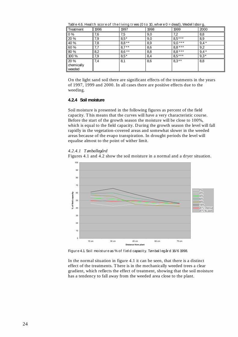
4.2.4 Soil moisture
Soil moisture is presented in the following figures as percent of the fieldcapacity. This means that the curves will have a very characteristic course.Before the start of the growth season the moisture will be close to 100%,which is equal to the field capacity. During the growth season the level will fallrapidly in the vegetation-covered areas and somewhat slower in the weededareas because of the evapo transpiration. In drought periods the level willequalise almost to the point of wither limit.
4.2.4.1 TønballegårdFigures 4.1 and 4.2 show the soil moisture in a normal and a dryer situation.
0
10
20
30
40
50
60
70
80
90
100
15 cm 30 cm 45 cm 60 cm 75 cm
Distance from plant
% o
f fie
ld c
apac
ity
0%20%40%60%80%100%20 % Chemical20 % No plant
Figure 4.1. Soil moisture as % of field capacity. Tønballegård 16/6 1998.
In the normal situation in figure 4.1 it can be seen, that there is a distincteffect of the treatments. There is in the mechanically weeded trees a cleargradient, which reflects the effect of treatment, showing that the soil moisturehas a tendency to fall away from the weeded area close to the plant.

25
0
10
20
30
40
50
60
70
80
90
100
15 cm 30 cm 45 cm 60 cm 75 cm
Distance from plant
% o
f fie
ld c
apac
ity
0%20%40%60%80%100%20 % Chemical20 % No plant
Figure 4.2 Illustration of a very dry situation, where the level probably is very closeto the wither limit. There are not seen any significant differences in treatment.
4.2.4.2 WedellsborgThe corresponding curves for the Wedellsborg trial can be seen in figures 4.3and 4.4.
0
10
20
30
40
50
60
70
80
90
100
15 cm 30 cm 45 cm 60 cm 75 cm
Distance from plant
% o
f fie
ld c
apac
ity
0%20%40%60%80%100%20 % Chemical20 % No plant
Figure 4.3. Soil moisture as % of field capacity. Weedelsborg 21/6 1998.

26
0
10
20
30
40
50
60
70
80
90
100
15 cm 30 cm 45 cm 60 cm 75 cm
Distance from plant
% o
f fie
ld c
apac
ity
0%20%40%60%80%100%20 % Chemical20 % No plant
Figure 4.4. Soil moisture as % of field capacity. Weedelsborg 21/8 1997.
The gradient in the normal situation in figure 4.3 is much more distinct andreflects the effect of the treatment.
In the dry situation the level of moist in the mechanical weeded areas near theplants has come down to almost the same level as in the not weeded areas.
4.3 Other investigations
In each growing season the time of bud breaking, frequencies of leader shotsand mean number of branches in the top whorl were recorded. Theseparameters, however, were not affected significantly by the differenttreatments.
4.4 Discussion
Christmas Tree producers are basing their cultivation systems on traditionand practical experience, which has indicated that the Nordmann’s fir isresponding to the weeding with better prosperity, growth and quality.Traditionally a 100 % weeding is therefore carried out in the Christmas treeplantations. In the trials reported here the trees have appeared to besurprisingly little influenced by the degrees of weeding above 40 %. Thus itcan be expected that fully satisfactory cultivation can be maintained with aconsiderably reduced level of weeding.
On both study sites the development of height has only been slightlyinfluenced by degrees of weeding above 40%. The root collar diameter, whichnotoriously is a parameter very sensitive to treatment, only responds very littleon degrees of weeding above 40%. The general state of health of the trees hashardly been affected by degrees of weeding above 20%. Regarding thearchitecture of the trees the trials show that the number of trees with leadershot defects does not seem to be influenced by the degree of weeding, just asthe type of defect also seems to not be influenced. This last issue is veryimportant as trees with more than one leader shot can be corrected by cuttingoff the extra leader shoots, and thus get into perfect shape. In contrast treeswith no leader shot at all are very difficult to repair. Also the number ofbranches in the branch whorl does not seem to be influenced by the degree of

27
weeding. The missing influence of the degree of weeding on the architectureof the trees is in good accordance with the fact that the time of bud breaking isalso not influenced by the degree of weeding in the trials. In this connection itis important to remember that the risk of spring night frost damages partlydepends on the time of bud breaking and partly on the locality. The trials areplaced on coastal areas and are thus not very likely to be exposed to springnight frost damages.
Regarding the soil moisture the TDR measurements from the trial shows thatunder normal circumstances in he areas with graduated mechanical weeding,there is more plant available water close to the trees than in areas withuntreated soil. The TDR data also show that the mechanical weeding can beregarded as an insurance because soil drying out in drought situations occursmore slowly in the mechanical weeded soil than in the vegetation covered soil.
4.5 Sub conclusion
To date, the he trials show that fully satisfactory cultivation results can beachieved on light as well as relatively heavy soils with area graduatedmechanical weeding with a weeding degree of 40%, corresponding to aweeded circle shaped area of app. 0,5 m2 around each plant.
28
5 Specification of stakeholderrequirements
Frans TheilbyThe Danish Forest and Landscape Institute, Department of Forestry
Spyros Fountas and Henning NielsenThe Royal Veterinary and Agricultural University, Section forAgroTechnology
An important part of developing new technology is to define the desires orrequirements of stakeholders, i.e. the future growers, operators, manufacturersand maintainers of the system. Those users know the circumstances underwhich the system should work as well as the function and shortcomings ofpresent systems. They are also the people that have to live with the newsystem and its properties in relation to people, work tasks and theenvironment.
To get a good basis for the development work a workshop was organised withthe project team and representatives from important stakeholder categories onthe 5th of March 2001. The participants contributed with presentations onvarious aspects of Christmas tree production and on ideas in relation todevelopment of an autonomous Christmas tree plantation (ACW). After thisa brainstorm session was arranged to identify the current level of satisfactionwith spraying and mechanical weeding as well as a specification of stakeholderrequirements and wishes for an ACW. The main outcome of this process isreported in the following.
5.1 The current level of satisfaction with spraying and mechanicalweeding technology
Weeding in the plantations is primarily done to reduce the direct competitionfor water, nutrients and light; however heavy weeds in Christmas treeproductions can also lead to wear damages, which are deteriorating to thequality of the trees. Furthermore, various weed species which are deeplyrooted in the plantation can restrain or even totally ruin a Christmas treeplantation. In general the need for weeding is greatest in the phase ofestablishing the plantation to secure survival.
Approximately 70% of the producers are using chemical weed control to someextent. Especially when using system 1, which mainly is used within fieldplantations, the use of chemical control is widespread.
Among growers the general attitude is that it is desirable to introduce moreenvironmentally compatible weed control methods, if these also technically,economically and effectively are alternatives. The use of chemical weedcontrol, especially the use of chemical soil weed control, has been stronglyreduced in the recent years. The improvement in spreading techniques, e.g.

29
band spraying and screened spraying, has also contributed to a reduction ofthe use of pesticides.
A political wish to reduce the use of pesticides has also contributed to theintroduction of various alternative weeding methods such as mechanical weedcontrol and weed control with animals. These methods are currently beingimproved and refined, but in general they are still too expensive. The cost ofthese alternative methods are 10-100% higher than spraying. At a time withdecreasing income per tree produced it is only natural if the producers aretrying to avoid increasing production costs, including weed control costs.
In general it is not the quality of the alternative weed control methods that isthe main problem, but the higher requirement of manpower that thesemethods imply.
5.2 Stakeholder requirements to an ACW
In the project stakeholder requirements were specified on the basis of aworkshop with participants from the various stakeholder categories:
Requirements:• Costs should be at most at the same level as chemical weed control• Able to work on steep gradients and irregular soil surfaces• Able to carry different tools, e.g. weed cutter and tillage tools• Safe in relation to humans and animals• Less than 5% trees damaged• Simple ACW transport• Easy maintenance (standard spare parts)• Secured against theft• Able to record important properties of trees and plantation
Wishes of additional work tasks:• Basal pruning• Fertilizer application• Spot spraying• Tree marking for sale• Shape regulation• Growth regulation• Transport of equipment for production measurements• Recording of tree properties for management and on line sale
purposes• Selective planting of new trees• Selective tree felling (and possibly transport trees to a field handling
point)• Selective replanting• Spatially selective processing according to needs.
In relation to the development stakeholders indicated that it is essential to getclarification about:
• The frequency of treatment• The appropriate periods of treatment (from the middle of May, the
beginning of July should be avoided for bud breaking reasons)• The possibility of combining different working operations.

30
5.3 Sub conclusion
The stakeholders found it desirable to introduce autonomous technology formechanical weeding in order to reduces environmental effects and labourrequirements, but this new technology should be competitive to the presentmethods. Also the stakeholders were interested in autonomous machines for anumber of other work tasks.

31
6 Specification of technicalrequirements for an autonomousChristmas tree weeder
Henrik HaveThe Royal Veterinary and Agricultural University, Section forAgroTechnology
Bent KellerThe Danish Forest and Landscape Institute, Department of Forestry
On basis of the described cultivation methods, minimum weed controlrequirements and stakeholder requirements the following full and reducedoperation scenarios and requirement specifications have been specified asgoals for the first generation autonomous Christmas tree weeder (ACW).
6.1 Overview of cultivation methodology
Christmas trees are mostly grown on farmland in rows 90 to 125 cm apartand with similar intra row spacing. Another pattern is a 60° triangular pattern(referred to as rhombic), which corresponds to closest packing of equal sizecircles. Using this latter pattern about 20% more trees can be grown on thesame area. Different tree species are chosen depending on the soil types.
The production cycle starts when typically two year old trees (about 20 cmhigh) are planted on prepared land, and it ends after 6 to 10 years when thetrees are cut selectively. In some cases new, small trees are planted in betweentrees remaining from this selective harvest.
Mechanical weeding during the first two years after planting is normallyperformed with special spring tine harrow (langfingerharve) developed forweeding in agriculture (see chapter 4), which is relatively cheap, and yields asatisfactory result. At the later growth stages this method is not suitable. Thisis when the ACW is to be employed.
Weeding is needed until the trees are about 1,5 m high. It must at least cover acircular area of 40 cm radius from the stem to avoid competition and stiffshoots of perennial weeds (including trees) to cause mechanical damage to thebranches.
The weed control may be performed either as shallow soil tillage or as weedcutting near the ground. The latter provide sufficient reduction of weedcompetition, but in some areas it is an advantage to clear the soil around thetrees during springtime, as it reduces the risk of frost damage of emergingshoots. A shallow form of soil tillage is considered suitable for this purpose.Weeding should be done 4 – 8 times a year (chapter 4). Recently emergedshoots are brittle and easily damaged mechanically.

32
About 6 years from planting, when the trees are about 1 m high, some of thelower branches of the trees are removed to reduce the top shoot growth. Thisoperation is in some cases done twice. Further growth regulation is sometimes made by removing part of the bark around the lower part of the stem.
Late in the growing period tracks may be cleared in the plantations fortransport depending on the harvest strategy (chapter 3).
6.2 Definition of operation scenarios for the ACW development
It is clear that the full range of plantation scenarios occurring in practicalconditions is wide, and that it would be difficult and costly to develop anautonomous machine that could cope with all situations. Therefore asomewhat narrower range of scenarios is chosen for the analyses.
Table 6.1. Christmas plantation parameters and requirements chosen for the ACWdevelopment.Category Parameter Occurring conditions Chosen machine requirements
Unevenness < 5 cm from average < 5 cm from averageAmount and type ofresidue
First generation: Noresidue.Second generation:Branches and stubbles
None: Residue to be clearedbefore second generationplanting
Inclination < 12 % <10 %Traffic ability Dry to slippery Dry until normal traffic ability
levelPhysical obstructions Stones, stubbles from
previous generations,branches
None
Soilsurface
Plant coverage Bare to dense Bare to denseHeight 5 to 200 cm 25 cmWeedsCoverage None to dense None to denseHeight 0.2 to 2.5 m 0.2 to 1.5 mAge 2 to 12 years Third to fifth yearBranch location aboveground:• at the trunk ->• at the branch tip -
>
Depends on species and age• 0–20 cm• 0–30 cm
Min. 5 cm
Tree size,andshape
Trunk diameter 3 – 8 cm 3 – 8 cmTemperature -5 to + 35 -5 to 35ClimatePrecipitation All Resistance to rainAnimals Dears
Nests and youngstersAvoid stationary items greaterthan 10 cm
Uncon-trolledobjects People Curiosity, larceny Stop, send alarm
In addition the mechanical damage of trees between planting and harvestshould be less than 5%. Also any contact between trees and the ACW shouldbe gentle or avoided during 3 weeks from medium May when the bud arevery sensitive to damage.
6.3 Definition of work tasks
During the workshop and further analyses (chapter 5) the followingoccurring as well as new work tasks were identified as suitable for one ormore autonomous machines. However it was decided to limit this initial workto weeding while keeping the other potential tasks in mind (Table 6.2).

33
Table 6.2. Work tasks considered in the present analysis.Work tasks Main parameters Possibilities Choice
Method Weed cutting, tillage andothers
Weed cutting
Tool Rotary cutters, drum cutters Rotary cutter withhinged exchangeableknifes
Weed development stage Early to late Relatively early
Weedcontrol
Frequency of operation Four to eight Ad-hocFrost riskreduction
Removal of weeds andtrash around trees
Usual cultivation method.ACW with tillage tool.
Usual cultivationmethod
6.4 Sub conclusion
In conclusion it is recommended to focus on development of an autonomousvehicle for weeding with rotor cutter near the ground in a slightly reducedrange of occurring scenarios. Further development of the vehicle for some ofthe other tasks appears feasible, but should be postponed to a later stage.

34
7 Autonomous vehicle technology –a literature review
Henning Nielsen and Spyros FountasThe Royal Veterinary and Agricultural University, Section forAgroTechnology
Autonomous vehicles (also called mobile robots and robotic vehicles) arenormally categorized as developments from automatic steered vehicles andremote controlled vehicles, while the term robot usually is used for materialshandling and tool operating automata mostly used in industry. Varieties of thetwo have found use in agriculture. An example is the experimental, roboticfruit harvesters developed years ago, which moved (autonomously) from treeto tree and picked the fruit by mean of an robotic arm. Another example is themilking robots, which are used in practical farming, milking the cows whenthey prefer. Human like robots ought to be regarded as an entertainmentindustry phenomena.
The most primitive robots, sometimes called industrial robots are just materialhandlers, mostly pneumatic, typically running through a process of gripping awork piece, carrying it and placing it in another place and returning to startthe next cycle. True industrial robots are versatile equipments able to be setup to perform work tasks like seam welding, painting, moving a work pieceand assemble components. To do this it should be reprogram able in an easyway without physical changes, have a memory and logic to be able to workindependently and automatically and further have a physical structure of afashion that allows for its use for several tasks without major restructuring(Lundquist, 1996).
Another area relevant to mention about work on robotics and autonomousvehicles is toys. The LEGO Mind stones products have by themselvescontributed to the development, but the products have also been found usefulas experimental modelling tools. Works like Rooker & Lund (2001) may beapplicable for developing the man-machine interface for the operators settingup the work of autonomous machinery. This reference describes aprogramming tool for LEGO robots to be used by children for setting upautonomous robot soccer players.
Autonomous mini sub-marines designed for under-sea prospecting and searchare mentioned by different sources, their relevance for the actual purpose isjudged to be limited.
Going into the real life of designing autonomous vehicles, Gomi (2001) statedthe priorities of hardware units to be: Battery, motor, connector, sensor, cpu.
The greatest future application of autonomous vehicles, many with roboticactions, is expected to be for domestic purposes including assistance todisabled people (Christensen, 2001; Gomi, 2001). At present most work inthis area is at the pre-commercial stage. An exception is a vacuum cleaner

35
from Electrolux. Although the research on other of these types of equipmenthas reached a rather high level of perfection, marketing for end users mustprobably wait for some time for safety reasons. However there is a great rangeof commercial vehicle types available as platforms for research purposes(figure 7.1). Some of these contain controllers with great computing capacity.
Figure 7.1: Example of skid steered commercial available autonomous vehicle platform forexperiments. The unit is electric powered from batteries and fitted with basic sensors, computersand communication equipment, which are open for addition of supplementary units.
7.1 Automatic and autonomous vehicles in agriculture, forestry andhorticulture
Petersen (1985) described some possibilities for application of robots inagriculture and mentioned picking of fruit, harvesting of vegetables as well astransplanting and spraying. Research has been reported on robotic harvest ofapples, grapes and oranges (Burely et al. 1990), robotic harvest of apples(Kataoka et al. 1997), robotic pruning of grapes (Lee et al. 1994) and roboticharvest of vegetables (Hilton, 1997).
Kondo & Ting (1998) describes a number of robots for fruit and vegetableharvesting. Robots for other crop growing operations are also shown. Many ofthe robots are mounted on vehicles, some without an operator. Apparently thedescribed robots rank from commercial to experimental. The treatment showsthe importance of sensors as part of the robots. Reports related to roboticweeding, e.g. Molto (1997) mostly consider weed sensing, in most cases usingvision systems. According to Kondo & Ting (1998) the interest for robotictractors (~autonomous tractors) in Japan is increasing.
Except for some robotic equipment mentioned above the only autonomousvehicle marketed for agriculture-related purposes seems to be lawn movers.Most well-known are two types sold by Husquarna, one solar poweredanother with battery loading from a mains connected servicing station that themachinery drive to when needed. These lawn movers move the grass in arandom linear pattern like the abovementioned vacuum cleaner formElectrolux.
Autonomous vehicle platforms for experiments are commercially available,e.g. from Applied AI Systems, Inc. (2001)(figure 7.1). This firm offers anumber of different types (called robots), mostly for indoors use; a few can beused outdoor. The problem is that the latter types are skid-steered, which isnot very suitable for weeding purposes. Up to now no commercial vehicleplatforms, which are easy to adapt for development of an autonomous weederhave been found.

36
An apparently more suitable vehicle platform has been made by Madsen &Jacobsen (2001) (Figure A.2, appendix A) as their M.Sc. thesis project. Thisis a robotic vehicle designed as a carrier for weeding purposes. The vehiclehas four-wheel drive four-wheel steer and is designed by mechatronicsprinciples with individual steering motors at each wheel
7.2 Evolution of automatic steering for agricultural vehicle
Experiments on ideas of removing the tractor driver or easing his steering jobhave already been reported from 1909 (AGRI/WP.2/69, 1962). Since thenthe technology has developed to make automatic steered vehicles possible. Asstated in a review by Wilson (2000) the fact is that for automatic steering ofagricultural vehicles of today the guidance will in most cases use GPS (GlobalPosition System) for absolute position sensing and vision systems (imageprocessing systems) for relative position sensing. A further element necessaryfor practical automatic steering are controllers based on computers withreasonable computing capacity.
The history of automatic steering of agricultural vehicles can briefly bedivided in two epochs. Until about 1940 the experimens had mostly been onmechanical systems. A prominent result was furrow followers delivered asstandard equipment for some tractors. Remote radio control of tractors wasdemonstrated in 1936. During the second world war servomechanisms wereput into general use. This developed the theory of control systems.
From the 1950’es to the 1980’es a great amount of research on automaticsteered agricultural machinery was performed. Reviews of this is found in thereferences above and in Jahns (1976) and Nielsen et al. (1976). A great partof this research considers sensor principles for guidance information. Furtherresearch considers design of the control systems, some on more generallyapplicable principles and mostly on detailed electronic design with minorrelevance today. Liljedahl et al. (1962) applied the theory of automatic controlon automatic tractor steering and by this introduced application ofmathematical modelling or systems analysis into the subject.
In the 1970’es the increased application of electronic instrumentation foragricultural engineering research was crossbreed with electronic control forthe advance of both topics, and at the end of the decennium themicroprocessor was introduced in some systems. The decade also saw the firstsimple electronic monitoring instruments in practical farming.
During the 1980’es electronic equipment found more widespread use inpractical farming, mostly monitoring equipment and some simple controls. Inthis decade also targeted work to increase the quality of farm electronics hadbeen performed. Development and standardization of data bus systems foragricultural tractors were also started up in this period.
In the 1990’es the concept of precision farming brought positionmeasurement (~ navigation systems) into practical farming with GPS (GlobalPositional System) in practice becoming the universal sensor for absoluteposition. To obtain sufficient accuracy error correction using differential GPShad to be used, but since the intentionally introduced error (selectiveavailability) has been removed other means of obtaining accuracy havebecome possible. However, for guidance purposes the accuracy obtained by

37
these systems is not sufficient. In stead RTK GPS (Real Time KinematicGPS) has to be used. The RTK system extends the differential principle withcorrections based on application of the GPS carrier wave phase.
The 1990’es also saw the development of image processing systems able toprocess relatively complicated images nearer to real time. These systems werepartly developed to become research measurement tools, partly researched forpost harvest processing of horticultural products (Bennedsen et al., 1996;Bennedsen & Kohsel, 1996; Bennedsen, 1997). Some of the latter have beendeveloped into systems, which now are inserted into production lines inhorticulture (Anonymous, 1997). Further research has been made onapplication of image processing systems for application by control of fieldmachinery, e.g. fruit picking (Peterson & Bennedsen, 1999), weed detection(Pedersen, 2001) and guidance in row crops. The latter has been developedinto control systems marketed for guidance of row crop cultivators(Bundgaard, 2001).
An updated broader overview on automatic steering of farm vehicles can befound in a thematic issue (no. 25, 2000) of Computers and Electronics inFarming.
7.3 Sensors for navigation
The primary sensors needed for navigation are systems that can provideinformation on absolute and relative position, vehicle absolute and relativeorientation and speed. Supplementary systems may be needed for specificpurposes. Many other sensor types may also be used internally in machineryand for crop sensing, e.g. tactile sensors for mechanically sensing presence ofmaterial or force from material. It is worth noting that some in generaloutdated guidance principles have properties, which may make themcandidates for special applications.
7.3.1 Real time Kinematic global position system
As mentioned above navigation (~guidance) of automatically steered vehiclein future is today assumed mostly to be based on measurement of the absoluteposition based on RTK GPS (Real time kinematic global position system)and relative position determined by vision.
The RTK GPS is based on measurements of the propagation time for theradio waves from the Navstar satellites. The RTK principle is based onapplication on a local ground based reference station and obtains centimetrelevel accuracy using the carrier wave phase difference. The principles aredescribed in a number of textbooks and articles. A short technical descriptionof an actual system is, e.g. found in a manual from Trimble (1999). As aminimum a GPS equipment will deliver horizontal coordinates in a groundbased coordinate system, but most provide also the vertical coordinate, timeand additional information, e.g. about accuracy.
7.3.2 Computer vision
This technology is in many cases based on use of video cameras, oftencommon colour cameras (giving RGB colour information) or grey levelcameras. In some cases cameras with other spectral sensitivities or even morespecial camera types are used. The camera signals are after digitisingprocessed computationally to extract relevant sensor information, e.g. the

38
vehicle heading relative to a crop row. A great amount of literature existsabout vision systems and image processing. A part of this is about vision forguidance purposes.
7.3.3 Supplementary sensors
Besides both the above primary navigational sensor systems reliable guidanceoften will depend on supplementary sensors, among others to detect theangular orientation/attitude of the vehicle. This comprises the threeparameters: Heading, roll and pitch. The heading is the direction of drivingexpressed as an angle relative to another direction; it is primary informationfor control of the steering. Absolute measure for heading is the compasscourse. Different compass sensors are available, but the heading can also becalculated from a number of subsequent position measures when driving. Rolland pitch are the angular deviation of the vehicle’s vertical axis from the actualvertical, roll is the sideward angle and pitch is the up-down angle of thevehicle’s forward direction. Both can be measured with inclination sensors.For accurate position determination with RTK GPS roll and pitch are oftenneeded for correction because the GPS aerial is placed at a higher level thanthe tool to be positioned.
In some cases information on driving distance and velocity are needed for agood control of vehicle driving. This can be supplied by an odometer. Formeasurement of shorter distances or as an alternative to vision, sensors basedon ultrasound can be used.
7.3.4 The leader-cable principle
By this principle the vehicle follows a single cable buried below the track. Thecable carries a voice frequency alternating current. The approach iscommonly used for automatic transport systems in industrial plants, where thedriver-less vehicles have bumpers operating safety stops to avoid damage onpersons or other objects in the vehicle path. Variants of this system have beenused or been tried for quite a lot of applications. A system for farm use wasdescribed by Morgan (1958) and since then more advanced experimentalsystems have been described, e.g. Jahns (1976,b). Bearing some resemblanceto the present project, is the application for automatic lawn movers where thecable signals the limit of the area to be moved. Some automatic movers alsouse a leader cable for homing guidance to a servicing station. In a GPS-basedsystem a leader cable could be used as part of an emergency subsystem.
7.3.5 Laser-based principles
The use of lasers has possibilities for high accuracy in areas where line of sightcan be obtained. Using a laser beam as a very straight guidance line is used fordifferent purposes. Lasers can be used for accurate measurement of angles inone or two dimensions by mechanically scanning the beam in a plane angle ora solid angle respectively. Further the distance can be measured by means of amodulated laser beam reflected back into the instrument with the laser.Distance measurement and angle scanning is sometimes combined in oneinstrument.
A commercial version of this combined principle made for accurate guidancein limited areas is described by Arnex (1995) and Søgaard (1998). Thesystem has a laser scanner on the vehicle and uses reflective fix-pointsinstalled around the field in positions accurately surveyed. The system delivers

39
two measurements per second for each reflector. Because of the lowmeasurement frequency the equipment has a Kalman filter, which is asoftware estimator to extrapolate into the time interval between lastmeasurement and the time when next position coordinates have beenmeasured and calculated. Another remarkable feature is optics to broaden thelaser beam so the light intensity is reduced to eye-safe level.
Laser scanners and laser distance-meters may be used as test instruments.Kalman filtering is generally applicable for real time purposes e.g. in controlsystems with time discrete and noisy signals. Laser scanners may also beapplicable for replacements of vision systems, especially if range data arerequested for 3d imaging.
7.3.6 Other principles
Other relative position sensors with possible relevance are mechanical typeswith a feeler arm. For instance the type used for sensing maize stalks(Kutzbach & Quick, 1999; Suggs et al., 1972), could be modified for sensingChristmas tree trunks.
Simple optical sensors sensing presence or non-presence of material havebeen used for many purposes, but not very many have been used in fieldmachinery because of the risk of contamination.
Simple optical sensors with ability of discriminating between green plants andother materials have been used experimentally in the 1970’es (Palmer &Owen, 1971; Hooper et al., 1976). The special relevance is that these sensortypes, instead of using the green colour used the more pronounced differencebetween red reflectance and near-infrared reflectance of green plant materials;this feature is also used in some modern vision-based systems.
Tillet (1991) has produced a more recent review of automatic guidancesensors for agricultural field machines.
The topic “degree of autonomy” has been discussed by Castelfranchi (2001).Degree of autonomy is approximately the same as “level of delegation”. Thetopic brings in a lot of implications partly of rather philosophical nature.
7.4 Safety
Safety of machinery working without continuous human supervision iscritical. Apart from the functional reliability the machinery must not hurthuman or animals and should neither damage third persons property. Forunmanned machinery working in open country the problem of possible entryby unwanted persons into the work area is serious.
The controller must handle safety problems as part of its operation. In thecase of damage to the machinery or other error conditions the design of thecontroller and the rest of the machinery must assure a safe function with agraceful degradation.
For the matter of safety of third parties and the operator an alternative outerlayer of safety must be provided. In most cases this will be performed by ahardware safety system independent of the controller. In particular themachinery must stop if children or animals are coming near, but not if theoperator or another authorized person is present in a safe way.

40
The safety systems must comply with the rules set up by safety at workauthorities. A first approach for safety of an area with working machines isfencing with safety switches stopping the machines in case the fence isopened, a solution which may be prohibitively costly in the case of weedingmachinery and also a problem in relation to the work of an operatorsupervising the work now and then. In general if a specific machine is notcovered by special rules the safety system of an actual machine will be judgedto comply or not with a generalized set of rules. Danish rules possiblyapplicable to the safety of autonomous field machinery are at least partlycovered by the rules for remote control of technical equipment(Arbejdstilsynet, 1995a) and the rules for automatic controlled machinery,industrial robots included (Arbejdstilsynet, 1995b).
An elementary set of safety demands to automatic steered agricultural vehicleshave been set up by Jahns (1975).
7.5 Systems Architecture
An architecture is a description of how a system is constructed from basicsand how those components fit together to form the whole (Albus, 1991).
Mobile robots, if they are to perform useful tasks and become accepted inopen environments, must be autonomous: capable of acquiring informationand performing tasks without programmatic intervention. Due to thecomplexity and intelligence of an autonomous vehicle it is necessary toincorporate systems architecture already in the design phase. As a result, theliterature review is derived by the Artificial Intelligence and Robotics.
There are not many references about systems architectures for autonomousvehicles in agriculture. Nilsson (1980), states that a control system for anautonomous tractor should be decomposed into three functional elements: asensing system, a planning system, and en execution system. The job of thesensing system is to translate raw sensor input into a world model. The job ofthe planner is to take the world model and a goal and generate a plan toachieve the goal. The job of the execution system is to take the plan andgenerate the actions it prescribes.
Later on, the sense-plan-act approach (SPA) became the dominant one in thisarea. The SPA approach has two significant architectural features. First, theflow of control among these components is unidirectional and linear. Second,the execution of an SPA plan is analogous to the execution of a computerprogram. Executing a plan or a program is easy when compared withgenerating one. Therefore, the intelligence of the system lies on the planner orthe programmer and not on the execution mechanism (Connell, 1989).
The next step of the sense-plan-act (SPA) approach was the “subsumption”approach, applying task-dependent constraints to the subsumption layers tomake SPA more efficient. The most well known example of this approach isthe mobile robot called Herbett’s which was programmed to find and retrievesoda cans in an office environment (Connell, 1989).
Rzevski (1995) mentions three main types of three systems architectures formobile robots. The hierarchies, networks and layered architectures.

41
A hierarchy is an architecture that consists of elements linked as “parents”and “children”. Each parent can have one or more children. Each child maybe a parent of other children. In this way multilevel hierarchies areconstructed. Hierarchies are used whenever it is necessary to reduce theperceived complexity of a system caused by its scale (size).
In networks, in contrast to hierarchies, there are no levels of importance andall elements may be connected to each other. These architectures are usedwhen there is a need for cooperation between units that are equal inimportance but different in terms of skills or capabilities.
Layered architectures, consist of self-contained elements, called layers, eachconnected to a set of inputs and outputs and thus each capable of creating asystem behaviour.
Moreover, from the artificial intelligence literature for mobile robots, thefollowing are some dominant system architectures, which have been widelyused in autonomous vehicles:
7.5.1 Three-layer architecture
The three-layer architecture consists of three components: a reactive feedbackcontrol mechanism, a reactive plan-execution mechanism, and a mechanismfor performing time-consuming deliberative computations. Thesecomponents run as separate computational processes. According to thealgorithms, which are going, to be executed in the processes they should fallinto three major equivalence classes.
The first one is the fast, mostly stateless reactive algorithms with hard realtime bound on execution time, slow deliberative algorithms like planning, andintermediate algorithms with hard real-time bounds on execution time. Slowdeliberative algorithms like planning, and intermediate algorithms, which arefairly fast, but can not provide hard real-time guarantees. “Fast” and “slow”are measured with respect to the rate of change of the environment (Gat,1998).
7.5.2 The Saphira architecture
This architecture design consists of three central aspects. The ability to attendto another agent, to take advice about the environment and to carry outassigned tasks. All three involve complex sensing and planning operations onthe part of the robot, including the use of visual tracking of humans, co-ordination of motor controls and planning. To be able to achieve theseaspects, the Saphira architecture uses the concepts of co-ordination ofbehaviour, coherence of modelling and communication with other agents.(Konolige and Myers, 1998)
At the coherence concept, a mobile robot must have a conception of itsenvironment that is appropriate for its tasks and consequently the more open-added the environment and the more complex the tasks, the more the mobilevehicle will have to understand and represent the environments. At thisarchitecture, an internal model is used, the local perceptual space (LPS)which uses connected layers of interpretation to support reactivity anddeliberation. The communication concept implies the ability to understandtask commands as well as integrate advice about the environment or itsbehaviour.

42
7.5.3 The animate agent architecture
The aim of the animate agent architecture is to design software systems forintelligent robotic agents. Such agents need to be able to pursue a wide varietyof goals and interact naturally with people when deciding which goals toachieve and how to achieve them. This type of architecture addresses theseissues using a two level model for encoding robot behaviour. A lower levelconsisting of continuous processes that control the robot’s sensors andeffectors and a higher level consisting of a reactive plan executor that selectssequences of actions and programs the lower level at run-time (Firby, et al.,1996).
The two level approaches is designed to cope with the following issues:
• The details of the world• Dynamic situations• Contingencies, problems and opportunities• The control of continuous processes• The integration of purposive vision
The architecture in general consists of a reactive task execution system, usinga hierarchical library of discrete plans and plan steps, and a continuouscontrol system using composable modules called skills. A two levelarchitecture is used to allow the encoding of two quite different, butcomplementary, types of robot behaviour. The skill level supports thedescription of continuous control processes, while the task execution levelsupports the description of multistep plans.
7.5.4 Behavioural reactive system architecture
A behavioural reactive system architecture tightly couples perception to actionwithout the use of intervening abstract representations or time history. This isdrawn from the behaviourist school of psychology which considers thatbehaviour is simply a reaction to a stimulus. The reactive robotic systems havethe following characteristics (Arkin, 1998):
• Behaviours serve as the basic building blocks for robotic actions• Use of explicit abstract representational knowledge is avoided in the
generation of a response• Animal models of behaviour often serve as a basis for these systems• These systems are inherently modular from a software design perspective
7.6 Sub conclusion
Autonomous vehicles, also called mobile robots and robotic vehicles, for usein open environments are in an early stage of development. No realautonomous machines have yet been marketed for practical purposes, but afew experimental types are being built and offered for sale for researchpurposes. A range of sensing systems is being developed to perceive necessaryinformation on position and structure of surroundings. Other work has beendone on processes for navigation, steering, safety precautions and otheroperational purposes. Various system architectures, including a range of

43
databases and processors, have been developed to facilitate this informationcollection, processing and utilization in an organised way.
44
8 Proposed outline of anautonomous Christmas tree weeder
Henrik Have and Simon BlackmoreThe Royal Veterinary and Agricultural University, Section forAgroTechnology
The idea of developing an autonomous machine for weeding in Christmastree plantations has come up in connection to general considerations of a newmechanization concept of using small agricultural autonomous machines. As aconsequence the present feasibility study has been made as part of a generalconcept development, which is presented in the three appendices:
• A specification of behavioural requirements for an autonomous tractor,• Proposed Systems architecture, and• General motivation of using autonomous vehicle systems.
These general considerations together with information and requirementspresented in the previous chapters forms the basis of the following proposedoutlines of autonomous Christmas tree weeder.
8.1 Weeder tool
The specified requirements of weeding (chapter 4) are that the weeds as aminimum should be cut within a 40 cm radius circle area around each tree asclose as possible to the ground. The operation scenarios that an ACW shouldcope with are specified in table 6.1, while the work tasks considered and themethods chosen are specified in table 6.2.
The simplest and most robust method for weed cutting is a rotary cutter,which is well-known from lawn mowers and agricultural forage mowers,which are available in many different designs and sizes. Figure 8.1 show somedifferent cutter unit designs with the cutter blade shielded in a housing. Thisis a good safety precaution but will require rather frequent cutting to preventweed plants from growing too large and vigorous to be bent beneath the cuttershielding.
8.2 Optimum operation pattern and vehicle positioning
Cutting of the minimum required circular areas around each tree may beperformed by a loop type operation pattern where the ACW travels aroundeach tree while cutting a band of 40 cm. Alternatively the ACW could travelparallel to the rows on either side (figure 8.2). Of these the parallel operationpattern is found to be the simplest and most favourable in terms of efficiencyand costs (see chapter 9).

45
Figure 8.1. Outline of different rotor cutter designs. The rotor may be mountedwithin a housing (a) to achieve maximum safety on the expense of ability to cut highrobust weeds, or the rotor may be mounted just below the housing (b and c) toimprove the ability to cut such weeds on the expense of safety. In all cases the shieldwill protect the trees, if the vehicle positioning should be insufficiently accurate.Type a and b are considered suitable for vehicle designs having the trailing wheelsmounted close to the rotor, while type c, which has a skid-pan underneath the rotor,is suitable for rotor placement in larger distance from the trailing wheels.
The parallel operation pattern means that the vehicle travels along the rowwith the rotor cutter overlapping the row centre line by a few cm. Whenapproaching a tree it may be designed to go about it by a quick sidewardreciprocal movement. Alternatively the rotor cutter may be moved side wardsin a similar way.
Figure 8.2. Parallel (top) and loop type operation patterns.
8.3 Vehicle concepts
Of the vehicle concepts described in appendix A the “beetle type” and theportal type was selected for closer examination.
8.3.1 The beetle type
The “beetle type” is a small lawn mower type of machine (figure 8.3). It onlytravels within the cut swath and is small enough to move relatively close to thetrees has a size suitable to move underneath branches and in between any twotrees in a plantation. It would not have any restrictions from the size of the

46
trees and would not cause problems of tree damage at headlands. In addition it would be suitable for weeding in a number of other tree and bush cultures, e.g. in horticulture. It is probably also the simplest possible design with a minimum of moving parts as the wheels are used to do all positioning relative to the ground and to the trees. For the same reason 4-wheel drive and 4-wheel steering would be important. The larger beetle type (figure 8.4) is somewhat more complicated but because of the floating rotor cutter suspension and skid-pad, it may have better abilities to work on uneven ground and to pass obstacles. The relative positioning of the rotor to the trees may in this case be done by one set of steering wheels, but it may be simpler to have the vehicle to travel on a strait line and to position the rotor cutter relatively to the vehicle by means of a simple control system. This beetle version could even carry a rotor cutter on either side with individual near positioning systems, which would double the capacity, but also make turning more difficult. Another disadvantage would be the low clearance, which would affect the leftover weeds between the rows. Also, extra space would have to be provided between the field border and the first row to provide enough space for the wider machine.
Figure 8.3. Outline of small “beetle type” ACW mounted with central placed rotor cutter.
Figure 8.4. Outline of large beetle type weeder with front mounted rotor cutter. A wide design is proposed to place the wheel traffic in the cut lanes only.

47
8.3.2 The portal type
The portal type (figure 8.5) would be a two-rotor type machine travelling with a set of wheels on either side of a row.
Figure 8.5. Outline of portal type weeder with two rotor cutters seen from the under side. This type would have limitations regarding the size of the trees, and would also be more complicated to turn on headlands. Another negative point is, that it would be unsuited for operation in most other tree and bush cultures. However the methods of controlling the cutter units into the intra-row area would be similar to those describe above.
8.4 Vehicle operation procedure and transport
It is proposed, that the ACW should work autonomous only within the borders of plantations or a group of plantations having common borders. Before starting the work and eventually at times during the work the operator will input work instructions into the controller by suitable means (e.g. radio or chip card). As part of the work instruction map information (GIS data) for the field borders, occurring obstructions and the tree location has to be provided. The controller will also get information from vehicle-mounted sensors to be used for vehicle guidance, control of the weeding tool and for check up on its own status. Having been placed in a plantation and given the necessary information the ACW should start to measure its own position and orientation in the field. Then it should work out the best overall operation strategy, i.e. the most efficient order of sub tasks. After that it should start the rotor cutter, move to the first tree and begin to work. Having finished the last tree the ACW should move to the point where it was started up, and report back to the supervisor. As the production of Christmas trees mostly takes place in small plantations an ACW would in most cases have to serve several plantations to improve utilization and reduce costs. Therefore, the machine would often have to be moved between plantations. This calls for a small, light machine, which is easy to move. One person may move, service and operate many machines simultaneously in one or more plantations at the same time depending on locations.

48
8.5 System architecture
To achieve the above-described operation of an ACW it must have acontroller, which can control machine movements and weeding tool functions.A proposal of a general type of system architecture suitable for this type ofcontroller is provided in appendix B. The information needed for thecontroller would be a priory information on the positions of plantationborders and trees (GIS database), technical specifications of the vehicle(ACW database and tool database), real time sensor information on the ACWorientation and position absolute and relative to trees and other nearby itemsof relevance to be able to move and work relative to these, as well as sensorinformation on the vehicle itself (self awareness and check). Using this datawould enable the ACW to work as described in section 8.4. To compensatefor inaccuracies of sensor information and positioning of the ACW thereseems to be need to sense tree positions relative to the vehicle.
8.6 Sub conclusion
Outlines were proposed of a weeder tool, various vehicle designs, operationpatterns as well as vehicle operation procedure and system architecture. Theweeder tool suggested is a shielded rotor cutter that can go close to the trees.For the same reason a small vehicle, being able to move beneath the branches,is considered best suited. An operation pattern of linear movement along treerows was found most efficient. To navigate such a vehicle appropriatelywould require sensors for measurement of position, orientation and structureof surroundings and others, as well as information on the position of the trees.The system architecture should be adapted to these characteristics.

49
9 Estimated performance of selectedrobot concepts
Henrik HaveThe Royal Veterinary and Agricultural University, Section forAgroTechnology
Having proposed possible outlines of autonomous Christmas tree weeders inthe previous chapter the purpose of the following is to estimate theperformance characteristics of these outlines.
9.1 Environmental benefits
Compared to the present practice of herbicide application the ACW weedingmethod has several advantages. Weeds can be controlled without use ofherbicides and some natural plant cover may be left over between the rows toimprove the biodiversity – an improvement that may help decreasingproblems of pests and diseases, and thus the use of pesticides to control these.
Compared to mechanical inter row weeding the method also has theadvantages that the soil surface is left nearly untouched and covered by plants,which will reduce problems of nutrient leaching and soil erosion. In additionthe energy consumption and CO2 emission will be much less, because cuttingrequires less energy than tillage, because only part of the area is treated, and alightweight vehicle is used. The low weight will also reduce soil compaction.
9.2 Effectiveness of weed control
As described in chapter 4 weeding of 40 cm radius circular areas around eachtree is enough to achieve good tree development. Both of the autonomousmachine designs outlined in chapter 8 will weed more than this minimum areaas they have to mow continuously between the trees. But still they will leaveabout 33 % (parallel operation pattern) and about 49% (loop operationpattern) of the area untreated. The weeds left in these areas may affect thetree growth positively as they provide shelter and increase biodiversity asalready mentioned.
However, problems may occur from large weed plants or trees developing inthe untreated areas. This may occasionally require supplementary treatments.
With the precision mechanisms used it is considered possible to weed within afew centimetres of the individual trees, leaving probably less than 1 dm2
untouched. Weed development in these areas is not likely to cause essentialproblems because of strong competition from the trees.
9.3 Machine caused losses
Machine caused losses may arise from traffic of vehicles and from injuriescaused by weeding tools.

50
Ignoring any possible negative effects of spray chemicals the only cause ofdamage associated to spraying may be mechanical injuries along sprayingtracks. Also, the damage caused by the present type of mechanical weedingimplements is little when they are properly used. It is estimated, that an ACWcould reach the same low level.
However when it comes to headlands the present normal size machineryneeds a rather broad area for turning, and because of the many turningsrequired, headlands are often not utilised or suffer from considerable damage.This problem would be solved or would become much less of a problem byuse of a small autonomous machine, which can move between the trees atheadlands.
9.4 Safety
The methods of achieving safe operation of the suggested ACW in relation topeople, animals, trees and the machine itself (described in appendix A and B)are considered sufficient, as the machine is to work in an enclosedenvironment, is small and is to use screened working tools.
9.5 Estimated area capacity
The term area capacity is defined as the area treated within a unit of time.The area capacity of the beetle type ACW concept was calculated by use oftypical or estimated data for the loop type and parallel operation patterns(figure 8.2 and 8.3). It should be noted, that the calculation refers to a design,where the rotor cutter is placed 20 cm off centre.
The parameter values and results are shown in table 9.1. It appears that theeffective area capacity (capacity in the defined practical conditions) of theparallel operation pattern is 56% higher than for the loop type. If the offcentre distances is reduced to zero the parallel operation pattern is superior byonly 4 %, as the vehicle then gets a shorter travelling distance, but this is notconsidered feasible when the tree becomes some years old, because of the lowbranches on the trees.
Table 9.1. Anticipated parameter values and corresponding area capacity of theselected types of ACW´s and operation patterns.Variable “Beetle”, loop “Beetle”,
parallelUnit
Row distance 1,2 1,2 mTree distance in row 1,2 1,2 mACW minimum distance to tree centre 0,02 0,02 mDistance from ACW centreline to cutter headcentre
0,2 0,2 m
ACW forward speed 0,75 0,75 m/sACW cutting width 0,4 0,4 mField efficiency 0,8 0,8 h/h
ResultsTime spent on each tree 5,12 3,20 sTheoretical area capacity 0,28 0,45 m2/sEffective area capacity 0,23 0,36 m2/sEffective area capacity 0,07 0,16 ha/h
The sensitivity of the results to changes in the assumed parameters values areshown in figure 9.1.

51
Tree distance
Row distance
Offcenter distance
Foreward speed
Cutting width-0,200
-0,150
-0,100
-0,050
0,000
0,050
0,100
0,150
0,200
0,250
Parameter
Are
a ca
paci
ty in
crea
se b
y 20
%
incr
ease
of t
he n
amed
par
amet
ers,
%
Figure 9.1. Sensitivity of the area capacity of weeding using an ACW in loop operationpattern.
From this it can be seen, that an increase of the forward speed and the rowdistance have high positive influence on the capacity. The same is the case forthe field efficiency, which is not shown. Increases of the off centre distanceand the cutting width have less and negative effects.
In case of the parallel operation pattern the field capacity will be proportionalto the forward speed, and the field efficiency, while the other parameters haveno essential effects.
9.6 Estimated costs
The level of costs associated with operation of an ACW was estimated using acalculation model and best judgement parameter estimates for differentoperation patterns, (table 9.2). It is of cause not possible to know how realisticthese values would be some years a head, but to take an example aconventional self-propelled lawn mower of a suitable size would cost around25000 to 35000 DKK. Transforming it into an ACW would require sensingsystems and controls, which probably will cost considerably more than that,when buying general-purpose equipment. However, prices are expected todrop when the equipment is adapted to the specific purposes, and theelectronic processes and software are compressed onto a few computer chips.As an example a general purpose RTK GPS, which now costs about 150000DKK, is estimated to cost 10000-20000 when adapted to a specific purposeand a general base station. Also the general drop in prices of electronichardware over time is likely to continue.
The cost estimate in table 9.2 shows an annual cost of around 3300 and 2400DKK/ha respectively for the two operation modes when weeding 20 ha. Thisvalue should be compared to the current contractor rates, which are 1000 –1500 DKK/ha for spraying of herbicides and 2500 – 3000 for mechanicalweeding.
To get an impression of the relative influence on the specific costs of thevarious parameters a sensitivity analyses was made. For both operation

52
patterns the analysis shows (figure 9.2), that the most important parametersare the area capacity, the parameters of the group of variable costs, and thenumber of annual weeding operations, while the purchase price and the areaallocated to a single ACW are less important.
Table 9.2. Duration and costs associated with the use of an autonomous weeder: Acase calculation bases on anticipated parameter values.
Variable “Beetle”, loop“Beetle”,parallel Unit
Anticipated purchase price 100000 100000 DKK
Fixed cost factor (depreciation + interest) 20 20 %
Annual fixed costs 20000 20000 DKK
Maintenance 15 15 DKK/h
Fuel and oil 10 10 DKK/h
Labour requirement (10 % of operation time) 10 10 DKK/h
Variable costs 35 35 DKK/h
Operational conditions (example)
Plantation area 20 20 Ha
Working hours each day 16 16 H/day
Number of treatments each season 5 5 1/year
Calculated work duration
Hours for one treatment 247 154 H
Days for one treatment 15,4 9,6 Days
Hours one season 1234 772 h/season
Days one season77 48 days/seaso
n
Costs
Fixed costs 15000 20000 DKK/year
Variable costs 43181 27006 DKK/year
Total costs 63183 47006 DKK/year
Specific annual costs 3159 2350 DKK/ha

53
Area capacity
Purchase price
Variable costs
Plantation area
Number of treatments
-20,0
-15,0
-10,0
-5,0
0,0
5,0
10,0
15,0
20,0
Parameter
Cos
t inc
reas
e by
20%
incr
ease
of
para
met
ers,
%
Figure 9.2. Sensitivity of the annual costs of weeding one ha using an ACW in theloop operation pattern.
Area capacity
Purchase price
Variable costs
Plantation area
Number of treatments
-15,0
-10,0
-5,0
0,0
5,0
10,0
15,0
Parameter
Cos
t inc
reas
e by
20%
incr
ease
of
para
met
ers,
%
Figure 9.3. Sensitivity of the annual costs of weeding one ha using an ACW in one-sided “strait” operation pattern.
There may be different opinions about whether the chosen parameter valuesare realistic ore not, but at least the calculations provide an idea about levelsand relative significance of the parameters. It appear to be important to finddesigns and operation patterns that provide high area capacity and lowvariable costs, while the ACW purchase price is less important. It also seemsto show that competitiveness in relation to the present mechanical weedingmachinery may be reached within a few years

54
9.7 Added values
The use of ACW´s in Christmas tree plantations opens possibilities of usingthe machine sensors and additional sensors to obtain information onindividual trees in the plantation. This could for example be size, shape,colour, and occurrence of large weeds near to tree trunks and between therows. This information could be used for improvement of managementdecisions like:• The optimal time of growth regulation (partial debarking or cutting of
lower branches), which may vary across the field,• Supplementary weeding of large weeds,• Spatial and single tree graduated application of fertilizer and pesticides,
Placement of fertilizers and pesticides close to the trees, e.g. carried out bythe ACW, to get maximum effect and minimum leaching.
In that way the consumption of auxiliary constituents can be optimised andmost likely reduced on plantation basis. At the same time systematic datacollection will enable a growth regulation in time and optimise the quality ofthe plantation.
The value of these opportunities could be quite considerable and wouldimprove the overall economy of the machine.
9.10 Sub conclusions
It is estimated that the proposed ACW system compared to presentmechanical weeding may deliver a better quality of work and considerableenvironmental advantages. On top of that there could be added values interms of tree specific data for management decisions and costumerinformation. The costs of the system are estimated to be similar to presentcontractor rates of mechanical weeding.

55
10 Conclusions
1. Current Christmas tree production occupies about 31000 ha and hasan annual turnover of 500-600 mill. DKK. There are about 4100producers, of whom the majority have less than 1 ha.
2. Most Christmas trees are produced on farmland. Typically two yearold trees are planted on prepared soil. They are cut after 6 to 10 yearsusing selective harvest. Planting patterns are typically square gridswith spacing in the range 90 cm to 125 cm.
3. Present weed control measures are mainly chemical (about 70%) andthe costs are about 20-25% of the total cultivation costs. Mechanicalweeding methods are being developed but are still relatively costly andcan mostly only do inter row weeding, which has limited effect and iscausing nutrient leaching and soil erosion.
4. The minimum requirement to weed control is found to be an area ofabout 40 cm radius around each tree corresponding to about 40% ofthe total area.
5. The requirements of stakeholders are that autonomous Christmas treeweeders should be competitive to present methods and fulfil theminimum requirement of weeding. Stakeholders also want to haveseveral other work tasks, i.e. growth regulation, spot spraying, spatialvariable fertilizing, and data collection, done by the autonomousChristmas tree weeder (ACW).
6. The technical requirements to an ACW were defined to cover mostplantation scenarios but not extreme cases. Also the workings tasks forthe first generation ACW were defined to weeding only, as thedevelopment of an appropriate controller system would be the firstpriority.
7. The general developments within sensing technology, computingtechnology and robotics has reached a stage where it is consideredrealistic to develop autonomous machines with appropriate behaviourfor regular agricultural and forestry field operations over longerperiods.
8. An analysis of different ACW design outlines and operation patternsrevealed that the most suitable system was a small machine being ableto move in between the trees in a simple operation pattern relative tothe location of trees, which are provided in a GIS database.
9. A suitable general type of system architecture was defined usingsensor information on position, orientation, surroundings structure,vehicle structure and self-awareness.
10. The environmental benefits of using an autonomous machine in thedescribed way were identified as:

56
• effective weed control without use of herbicides,• higher biodiversity because of left over weeds between the rows• reduction of nutrient leaching and water erosion• reduction of energy consumption.
11. The overall annual costs of weeding with a future ACW is estimatedto be similar to or less than the present costs of mechanical weeding.The costs are more sensitive to changes in the operation costs than tochanges in the fixed costs, which means that the purchase price of anautonomous weeder is less important.
12. Added values can be achieved by means of data from the vehiclesensors or additional sensors on tree conditions for managementdecision purposes, by fitting auxiliary equipment, which can provideindividual treatments of the trees.

57
11 References
AGRI/WP.2/69 (1962): Automation in agriculture. Economic Commissionfor Europe, Committee on Agricultural Problems, Working Party onMechanisation of Agriculture. 8. August 1962. (Non-revised translation fromRussian)
Albus, J. (1991): Outline for a theory of intelligence. IEEE Transactions onSystems, Man and Cypernetics, Vol. 21, No.3, May-june, pp. 473-509.
Anonym 1998: Rapport fra udvalget til vurdering af de samlede konsekvenseraf en hel eller delvis afvikling af pesticid anvendelsen (Bichel-rapporten)
Anonymous (1997): Computeren sorterer blomster (The computer sortsflowers). Product prospect, Thoustrup & Overgaard a/s, Randers, Denmark.
Applied AI Systems (2001): Products, Robots.http://www.aai.ca/products/robots/index.html.
Arbejdstilsynet (1995): Indretning af fjernstyring til tekniske hjælpemidler.At-anvisning Nr. 2.0.1.1, November 1995, DK.http://www.arbejdstilsynet.dk/services/exec/mask.exe?mask=framecont.msk&MyMask=BrList.msk&AREAPATH=regler&Categ=5 , (2000.03.14)
Arbejdstilsynet (1995 b): Automatisk styrede maskinanlæg, inklusiveindustrirobotanlæg. At-anvisning. Nr. 2.2.0.3. November, DK.
Arkin, R. (1998): Intelligent robots an autonomous agents. – The MIT PressCambridge, Mass.
Arkin, R., Balch, T. et al. (1993): Buzz: instantiation of a schema-Basedreactive robotic system. –Proceeding of the international conference onintelligent autonomous systems (AIS-3), Pittsburgh, USA.
Arnex (1995): Electro-optic sensors and position determination. Informationleaflet from: Arnex Navigation Systems AB, Stora Bådhusgatan 16, S-411 21Göteborg, Sweeden.
Bennedsen, B. S. (1997): Measuring Quality Potentials of Half-grown Pot-Plants., 3rd International Symposium on sensors in Horticulture, Tiberias,Israel, August 17-21, 1997.
Bennedsen, B. S.; Kohsel, L. (1996): Supervised and un-supervised featureextraction for classification of pot plants. - NJF-Teknik-96, 1996, Århus.
Bennedsen, B. S.; Moth-Poulsen; H. Kohsel, L: (1996): Objective qualitymeasurements of pot rose and hibiscus by image processing.- AgEng´96,Madrid 23-26/9. pp. 954-955. (Paper 96F-077).
Bennedsen, B.S. and Rasmussen, P. (2001): Plant spectra classification byneutral networks, 3rd European PA conference, Montpellier, France, June

58
Birrell, S.J. and Hummel, J.W. (1993): Multi_ISFET Sensors for Soil NitrateAnalysis. -Proceedings of the Soil Specific Crop Management: Research andDevelopment Issues, ASA, CSSA, SSSA, Robert, Rust and Larson (eds).p349
Blackmore , S. and Steinhauser, T. (1993): Intelligent Sensing and Self-Organising Fuzzy Logic Techniques Used in Agricultural Automation. ASAEPaper No. 93-1048 Spokane June 4 pp.
Blanke, M.; Staroswiecki, M. and Wu, N.E. (2001):Concepts and Methods in Fault-tolerant controlACC2001, Washington, USA, June
Bundgaard, S. (2001): Fire bud på optisk styring af radrenser. (Four bids ofoptical control of row crop cultivators). Landsbladet Mark, no. 3, (March), p.10. (Three articles).
Burely, A.; Rabatel, G.; Grand d’Esnon, A. & Sevilla, F. (1990): Fruit harvestrobotization: 10 years of CEMAGREF experience on apple, grape andorange. Proceedings: AgEng Berlin 1990, p. 178-179.
Castelfranchi, C. (2001): Invited talk. Seventh Scandinavian Conference onArtificial Intelligence. 20 - 21 February 2001, University of SouthernDenmark, Odense. (No paper. For further information see:http://pscs2.irmkant.rm.cnr.it/users/cristiano/home.html )
Chamen, W.C.T.; Dowler, D.; Leede, P.R. and Longstaff, D.J. (1994):Design, operation and performance of a gantry system: Experience in arablecropping. Journal of Agricultural Engineering Research, Vol. 59, Nr. 1, 45-60
Connell, J. (1989): A colony architecture for an artificial creature . Technicalreport 1151, Artificial Intelligence Laboratory. - MIT, Cambridge Mass.
Christensen, H.I. (2001): Invited talk. Seventh Scandinavian Conference onArtificial Intelligence. 20 - 21 February 2001, University of SouthernDenmark, Odense. (No paper. For further information see:http://www.cas.kth.se/ , http://www.nada.kth.se/~hic/ )
Earl, R.; Thomas, G. and Blackmore B.S. (2000): The potential role of GISfor autonomous field operations. Computers and Electronics in Agriculture,Elsevier, Special issue; Navigating Agricultural Field Machinery. Ed GerhardJahns, Vol.25 Issue 1-2, 1 Jan, pp. 107-120
Eco-Dan (www.eco-dan.com)
Ehsani, M.R.; M.L. Mattson and S.K. Upadhyaya (2000): An ultra-precise,GPS based planter for site-specific cultivation and plant specific chemicalapplication. 5th PA, Minneapolis, USA, July
Ellenrieder, K. (1996): Design of an autonomous agricultural vehicle.Unpublished Mphil thesis, Cranfield University

59
Firby, J., Prokopowicz, P. and Swain, M. (1998): The animate agentarchitecture. In: Artificial intelligence and mobile robots, edited by D.Kortenkamp, R.P. Bonasso and R. Murphy, AAAI Press
GEO-TEC, Am Soldnermoos 17, D-85399, Hallbergmoos-Munchen,Germany (www.geo-tec.de)
Gomi,T. (2001): Invited talk. Seventh Scandinavian Conference on ArtificialIntelligence. 20 - 21 February 2001, University of Southern Denmark,Odense (No paper. For further information see:http://fox.nstn.ca/~aai/gomib.htm )
Gat, E. (1998): Three-layer architecture. – In: Artificial intelligence andmobile robots, edited by D. Kortenkamp, R.P. Bonasso and R. Murphy,AAAI Press.
Grath T. ( 1997 ): Körning med tunga maskiner orsakar eller kan orsaka. In:Rapport från växtodlings- och växtskyddsdagar i Växjö den 9 och 10december 1997. Meddelande från Södra jordbruksförsöksdistriktet, no 48 ,ISSN 0282-180X, ISRN SLU-SJFD-M-48-SEhttp://zeus.bibul.slu.se/documents/slu/meddelande_sjfd/MSJ48/MSJ48AF.HTM
Hako Holding GmbH & co, Hamburger Strasse 209-239, D-23843 BadOldesloe, Germany (www.hako-werke.de)
Håkonson, I. (2000): Packing av åkermark vid maskindrift. – Report No. 99,Institutionen för markvitenskap, Sveriges Lantbruksuniversitet, Uppsala.
Hilton, D.J. (1997): A gantry machine for robotic harvesting of horticulturalrowcrops. 5th International Symposium on Fruit, Nut, and VegetableProduction Engineering. September 3-10, 1997, Davis California, USA.Organized by: Department of Biological and Agricultural Engineering,University of California, USA.
Hoffman, M. (1991): Machine Vision for row crop sensing. UnpublishedMSc thesis, Cranfield University
Hooper, A.W.; Harries, G.O. & Ambler, B. (1976): A photoelectric sensor fordistinguishing between plant material and soil. Journal of AgriculturalEngineering Research. Vol 21, p. 145-155.
Jacobsen, L.W.; De Jonge, H.; Villeholth; Ullum & Møldrup (2000):Pesticider bundet til jordpartikler kan udvaskes (Naturens Verden,Særnummer Pesticider, februar 2000).
Jahns, G. (1975):Safety demands for agricultural vehicles with automaticsteering. Paper no. 75-1028, For presentation at the 1975 Annual Meeting,University of California, Davis, California, June 22-25, 1975. AmericanSociety of Agricultural Engineers, St. Joseph, Michigan, USA.
Jahns, G. (1976): Possibilities for producing course signals for the automaticsteering of farm vehicles. In: Automatic guidance of farm vehicles amonograph. Agricultural Engineering Department, Series no. 1. AgriculturalExperimental Station, Auburn University, Auburn, Alabama, USA

60
Jahns, G. (1976,b): Einsatz induktiver Leitkabelsysteme zur Bearbeitung einerFläche mit fahrerlosen Fahrzeugen. Dr.-Ing. Dissertation, Fakultät fürMachinenbau und Elektronik der Technischen Universität Carolo-Velheminazu Braunschweig, Germany
Kataoka, T.; Ishikawa, Y.; Hiroma, T. & Ota, Y. (1997): Mechanisms ofapple harvesting by robots. 5th International Symposium on Fruit, Nut, andVegetable Production Engineering. September 3-10, 1997, Davis, California,U.S.A.
Keller, B. (1997): Mekanisk renholdelse af kulturer plantet på agerjord(Miljørapport nr. 353, Miljøstyrelsen 1997
Kondo, N. & Ting, K.C. (1998): Robotics for bioproduction systems. TheSociety of Agricultural Engineers, St. Joseph, Mi. USA. ASAE publication 05-98, ISBN 0-929355-94-6.
Konolige, K., Myers, K. (1998): The saphira architecture for autonomousmobile robots. -In: Artificial intelligence and mobile robots, edited by D.Kortenkamp, R.P. Bonasso and R. Murphy, AAAI Press.
Kutzbach & Quick (1999): CIGR Handbook of Agricultural Engineering,Volume III, p. 331. The American Society of Agricultural Engineers.
Liljedahl et al. (1962): Automatic tractor steering. –Agricultural Engineering,June 1962, p.322-335, 349.
Lee, M.-F.; Gunkel, W.W. & Throop, J.A. (1994): A digital regulator andtracking controller design for a electro-hydraulic robotic grape pruner.Proceedings of the 5th International Conference: Computers in Agriculture. 6-9 February 1994, Orlando, Florida, USA. P. 23-28.
Lundquist, J. (1996): Robotics course, introduction.http://www.ite.his.se/ite/research/automation/course/introtoc.htm(2001.03.12).
Madsen, T.E. & Jakobsen, H. L. (2001): Mobile Robot for Weeding. Masterthesis project, Department of Control and Engineering Design, TechnicalUniversity of Denmark. (http://www.gbar.dtu.dk/~928543/mobilerobot.pdf(January 31, 2001), http://www.ertboelle.dk/mobilrobot/ ).
Molto, E.; Blasco, J.; Alexos, N.; Carrión, J. & Juste, F. (1997): A machinevision system for robotic weeding of row crops. 5th International Symposiumon Fruit, Nut, and Vegetable Production Engineering. September 3-10, 1997,Davis, California, U.S.A.
Morgan, K.E. (1958): A step towards an automatic tractor. FarmMechanisation, November 1958.
Nielsen, H.; Christiansen, S.A. & Kofoed, S. Sonne (1977): A split-powerapproach: The M & S tractor system. Meddelelse nr. 31, JordbrugstekniskInstitut, Den Kgl. Veterinær- og Landbohøjskole, Danmark.

61
Nieminen, T.; Mononen, M. J. & Sampo, M. (1994): Unmanned tractor foragricultural applications. Proceedings. XII World Congress on AgriculturalEngineering. Milano, August 29 - September 1, 1994.
Nilsson, N. (1980): Principles of artificial intelligence. –Palo Alto, TiopaPress.
Palmer, J. & Owen, G.M. (1971): Automatic control of sugar beet singlingand thinning by means of an on-line digital computer. Journal of AgriculturalEngineering Research. Vol 16, no. 2, p. 107-125.
Petersen, T. T. (1985): Muligheder for anvendelse af robotter i landbruget.P.150- 164 in: Elektronik, mikrodatamater og robotter i landbruget. Indlægved det Kgl. Danske Landhusholdningsselskabs akademiråds seminar februar1985. Meddelelse nr. 51. Jordbrugsteknisk Institut, Den Kgl. Veterinær- ogLandbohøjskole, Danmark.
Pedersen, B.B. (2001): Weed mapping from digital images in spring barley.M.sc. Thesis (in preparation), AgroTechnology, Department of AgriculturalScience, The Royal Veterinary and Agricultural University, Denmark.
Peterson, D.J. & Bennedsen, B.S. (1999): A systems approach to roboticharvesting of apples. USDA, Appalachian Fruit Research Station, WestVirginia, USA.
Pöyhönen, A.; Allakku, L.; Aura, E. & Sampo, M. (1998): Soil compactionreduction in ploughed and stubble cultivated clay soil by using light,unmanned tractor. Paper no. 98-A-125, Proceedings from: AgEng Oslo 98,International Conference on Agricultural Engineering, Oslo, 24 - 27 August1998, p. 785 -86.
Rooker, M & Lund, H.H. (2001): Run-time Adaptation of Robot SoccerPlayers. P. 153-154 in: Seventh Scandinavian Conference on ArtificialIntelligence; Edited by: H.H.Lund, B. Mayoh & J. Perram. IOS Press,Amsterdam, ISBN 1 58603 161 9.
Rubow, T.; Friis, E. og Keller, 2000: Juletræer kan blive ”grønnere” . -Naturens Verden, Særnummer Pesticider, februar 2000.
Rzevski, G. (1995): Designing intelligent machines – Volume 1. The OpenUniversity, UK.
Schønning, P.; Munkholm, L.J.; Elmtoft, S.; Debosz, K.; Mikkelsen, G.H.&Trautner, A. (2000): Efterårsseminaret: Den danske dyrkningsjords tilstandog kvalitet - konsekvenser af trafik og jordbearbejdining. Tidsskrift forlandøkonomi. Vol. 187, no. 4. (december), p. 293 - 300.
Shibusawa, S. (1996): PhytoTechnology- An introduction to the concept andtopic of a new project. School of Bio-Applications and Systems Engineering,Tokyo University of Agriculture and Technology. (iacns.ishikawa-c.ac.jp/WhatIs.html)
Shibusawa, S.; Made Anom, S.W.I.; Sata, H.; Sasao, A.; Hirako, S.; Otomo,A.; and Blackmore, S. (2000): On-line real-time soil spectrophotometer. (5th
PA conference, Minnesota, July)

62
Steinhauser, T. (1993): Steering a Mechanical Weeder with IntelligentSensing using Machine Vision Unpublished MPhil thesis, CranfieldUniversity
Suggs, C.W.; Huang, B.K. & Davis, P.E. (1972): Automatic steering of fieldmachines. Paper no. 72-122, 1972. Annual Meeting, American Society ofAgricultural Engineers., Hot Springs, Arkansas, June 27-30, 1972.
Søgaard, H.T. (1998): Evaluation of the accuracy of a laser optic positiondetermination system. Paper no. 98-A-046. AgEng Oslo 98 Conference, Oslo,Norway.
Søgaard, H.T. and Olsen, H.J. (2000): A new method for determination ofcrop row position by computer vision. AGENG2000, Warwick, Paper 00-AE-016
Tillet, N.D. (1991): Automatic guidance sensors for agricultural fieldmachines: a review. Journal of Agricultural Engineering Research. Vol. 50, p.167-187.
Trimble (1999): MS750 Operation Manual, Part Number: 36574-00,Trimble Navigation Limited, Surveying & Mapping Division, 645 NorthMary Avenue, Post Office Box 3642, Sunnyvale, CA 94088-3642, USA.Waine, T.W. (1999): Non-Invasive Soil Properly Measurement for PrecisionFarming. Unpublished EngD Thesis, Cranfield University
Wayne, T.W.; Blackmore B.S. and Godwin, R.J. (2000): Mapping availablewater content and estimating soil textural class using electro-magneticinduction. AGENG 2000, Warwick, Paper 00-SW-044
Wilson, J.N. (2000): Guidance of agricultural vehicles - a historicalperspective. Computers and Electronics in Agriculture. Vol. 25, no. 1-2, p. 3-9.

Bilag A
63
A specification of behaviouralrequirements for an autonomoustractor
Simon Blackmore, Henrik Have and Spyrus FountasThe Royal Veterinary and Agricultural University,Section for AgroTechnology
1.1 Abstract
Over the last decade new information technologies, such as GPS and GIS,have been introduced that has allowed the scale of management to bereduced from farm level, down to field level and occasionally to sub fieldlevel. With the advent of new information technologies, such as behaviour-based robotics, this process can be continued into the future by looking at aneven smaller scale such as plant scale technology or Phytotechnology. (Fromthe Greek phyto, which means plant) These new Phytotechnology units willbe small autonomous systems that can behave in a sensible manner for longperiods unattended, caring for the individual plant from seeding through toselective harvesting. With this level of sophisticated equipment, it is likely thathigher value crops such as in horticulture or forestry will be able to justifysuch an investment first. Very little new hardware is needed but the challengeis in defining and implementing sensible behaviour and developing thesystems architecture to support it. This paper sets out the criteria for thedesign of such a system.
1.2 Introduction
To further improve the efficiency of developed agriculture, horticulture andforestry found in northern Europe a new concept is being developed that hasidentified that multiple small autonomous machines would be more efficientthan traditional large tractors. In order to meet this hypothesis a small tractorwith intelligent control is proposed. These vehicles will be able to work longerhours at a slower rate, giving the same, or even greater, overall output asconventional systems. Each vehicle would be capable of working 24 hours aday all year round, in most weather conditions and have the intelligenceembedded within it to behave sensibly in a semi-natural environment such ashorticulture, agriculture, parks and forestry, whilst carrying out a useful task.Moreover, it may have less environmental impact if it can replace the over-application of chemicals and the high usage of energy, such as diesel andfertiliser, by control that is more intelligent. Additionally, it will requiresmaller incremental investment and will have lower labour costs. Finally, itmay have very low soil compaction that would lead to a more sustainableproduction system.

64
Agriculture, horticulture and forestry has benefited in the past from asuccession of technological developments that have brought greaterproductivity and economic efficiency to systems operated in many regions ofthe globe. Historically, the emphasis of these developments has been on themechanisation of field operations to increase work rates achievable byindividual operators. Today, however, the general trend of increasedefficiency through the use of larger, more powerful, machines may besuperseded by the adoption of newer information based technologies thatmay ultimately enable reliable autonomous field operations to be viable (Earlet.al. 2000). A review of possible platforms was carried out by Ellenreider(1996) and a review of automatic steered tractors is given in Wilson 2000.
This scale-reduction process, started by Precision Farming, may lead to thepossibility of individual plant care systems called Phytotechnology. (Shibusawa1996) Precision Farming is a set of methodologies that utilise technologiessuch as the Global Positioning System (GPS), Geographical InformationSystems (GIS) and Management Information Systems (MIS) as well as thesensors and controllers in the field, to reduce the area of management fromthe whole farm down to field level and on occasions sub field level. Due tothe increased data processing required to cover a complete field at theindividual plant level, only certain operations are carried out with humanintervention these processes lend themselves to different forms ofautomation, especially in high value crops. Two good examples of thisprocess are mechanical weeding and field scouting.
1.3 Mechanical weeding
As most horticultural crops are grown in widely spaced rows, inter-rowmechanical weeding (weeding between the rows) has been popular sincemechanisation started. The only problem has been in assessing the relativedistance between the crop and the weeding tool, as nowadays it is difficult tokeep the tractor exactly parallel with the crop row. To overcome thisproblem, another operator is used to steer the weeding tool relative to thecrop row, but this increases the cost. Recent developments have lead to theuse of machine vision to recognise the contextual information of the croprows and steer the tool to within a few centimetres of the plants. This ideawas first tested in 1992 (Hoffman 1992, Steinhauser 1994) and has morerecently been commercialised by the Danish Institute of Agricultural Sciencesand Eco-Dan (Søgaard, 2000).
Intra-row weeding (weeding within the row) has proved to be more difficultdue to the problems of discriminating between crop plants and weed plants.A number of techniques have been tried notably categorising plants due totheir spectral reflectance characteristics. (Bennedsen 2001) These techniqueshave worked well in controlled environments, such as the laboratory, buttraditionally have not proved so reliable in natural lighting.
An alternative development has been to uniquely identify each individualcrop plant by recording the position of each seed as it was planted. (Ehsani2000) This is not as difficult as it sounds, as technology has developedsufficiently in the form of now standard high-speed PCs and the Real-TimeKinematic Global Positioning System (RTK GPS). Most desktop PCs caneasily manage the data rates required during planting as they can also storethe 100,000 seed positions in each hectare for Sugar Beet or 10,000

65
Christmas trees per hectare. The RTK GPS can resolve positions down to 1cm in stationary mode and 2 cm whilst moving slowly. As the plant positionsare now known, a mechanical intra-row weeder can be controlled to movearound each plant. Whether this level of accuracy can be maintained inagricultural conditions remains to be seen but a 2 cm systemic shift wouldresult in all the crop plants being removed! (NB Denmark is moving 1 cm tothe East each year).
1.4 Field scouting
There are many sensing techniques that that can ascertain crop and soilhealth. Many of them could be used now in production horticulture, apartfrom the fact that they take a long time to process the data. Examples aremulti-spectral response from the plant canopy that can indicate stress(whatever the cause) and chlorophyll content is associated with crop vigour.Carbon dioxide (CO2) has been associated with soil health, Ethylene can beassociated with pest attack and conductivity has been correlated with soilmoisture. (Waine 1999, Waine, et.al. 2000) Soil nitrates, organic matter,Charged-ion Exchange Capacity (CEC), pH and soil moisture have beenmeasured at different depths using Near Infra-Red (NIR) reflectance with asoil photo spectrometer. (Shibusawa 2000) Ion Selective Field EffectTransistors (ISFETs) can be modified to be sensitive to nitrates, pH andother factors from soil solution. (Birrell #) Most of these sensing systems arestill in the research phase but they hold great promise to improve ourunderstanding and management of the growing crop and its environment. Ifthese systems were mounted on an autonomous vehicle then they could beused commercially now and not have the associated problems of paying anoperator to wait in the field while the processing takes place.
1.5 Autonomous vehicle requirements
Both of these tasks (as well as many more) could be mounted on a smallautonomous vehicle that could roam the field carrying out its task overprolonged periods of time but to be able to achieve this the vehicle must havecertain attributes and behaviours.
The main design parameters for this proposed vehicle are that it is:• Small in size (and therefore unmanned)• Light weight• Exhibit long-term sensible behaviour• Capable of receiving instructions and communicating information• Capable of being co-ordinated with other machines• Capable of working collaboratively with other machines• Behave in a safe manner, even when partial system failures occur• Carry out a range of useful tasks
1.5.1 Small size
A small vehicle size is very meaningful as it ensures higher precision ofoperation, lower incremental investment and is relatively safe during systemfailures. The vehicles will probably be 1-2 metres long and in the 10-30 hprange, as they will require an internal combustion engine. An engine isneeded due to the energy - density requirement that battery power alonecannot supply. Smaller vehicles of less than a metre and around five hp could

66
be developed for highly specialised tasks with low energy requirements suchas non-contact sensing. Much smaller systems could be developed whenhigher density energy sources become available such as fuel cells. The controlsystems described here could be applied to any size platform. Incrementalinvestment and replacement of the vehicle and high production runs can beachieved by possibly using standard car components. The farmer’s and thepublic’s acceptance will be increased with the launch of small autonomousvehicles rather than bigger ones. These vehicles will have the advantage to bemore site-specific than larger machines, due to higher manoeuvrability.Inevitably, the smaller vehicle will have a lower work-rate but as it will beunmanned, it can work for longer hours to compensate. Using site-specificfertilising and spraying, it can achieve a further reduction in inputs, ifcombined with appropriate sensors These small machines will be able to doselective and more precise treatments and can potentially be developed tosense and care for individual plants or sub plant manipulation, e.g. thinning,pruning, selective harvesting etc.
1.5.2 Light weight
The lightweight design parameter is important as it implies reduced soilcompaction. Chamen (1994) has identified that a 70% energy saving can bemade in cultivation energy by moving from traditional trafficked systems(255 MJ/ha) to a non-trafficked system (79 MJ/ha). This was for shallowploughing and did not include any deep loosening. From this we estimate that80-90% of the energy going into traditional cultivation is there to repair thedamage done by large tractors. If we can accept the premise of a lightintelligent vehicle replacing the large tractors, there is the possibility todevelop a completely new agricultural mechanisation system. As we have thepossibility of very low compaction and mechanical weeding, then we do notneed to plough, but use micro-tillage and direct drilling, which could play amajor role in conservation agriculture. As the natural healthy soil bio-systemmodifies the soil structure into a near ideal situation for root development,almost zero compaction agriculture could be developed that allows thenatural processes to enhance production rather than introducing energy tocompact and then recreate a good soil structure. As the vehicle is inherentlylight, it should also require lower energy inputs although this is offset by thehigher efficiencies of the larger engines.
1.5.3 Autonomous behaviour
The main behavioural requirement of this vehicle is that it will have sensiblelong-term unattended behaviour in a semi-natural environment such ashorticulture, agriculture, parkland and forestry. This sensible long-termbehaviour is made up of a number of parts. Firstly, sensible behaviour needsto be defined, which at the moment is device independent. Alan Turingdefined a simple test (the Turing test) for artificial intelligence, which is, inessence, if a machine’s behaviour is indistinguishable from a person then itmust be intelligent. We cannot yet develop an intelligent machine but we canmake it more intelligent than it is today by defining a set of behaviour modesthat make it react in a sensible way, defined by people, to a predefined set ofstimuli in the form of an expert system. Secondly, it must be able to carry outits task over prolonged periods, unattended. When it needs to refuel or resupply logistics, it must be capable of returning to base and restocking.Thirdly, safety behaviours are important at a number of levels. The

67
operational modes of the machine must make it safe to others as well as itself,but it must be capable of graceful degradation when sub-systemsmalfunction. Catastrophic failure must be avoided, so multiple levels ofsystem redundancy must be designed into the vehicle. Fourthly, as the vehicleis interacting with the complex semi-natural environment it must usesophisticated sensing and control systems, probably in an object orientedmanner, to be able to behave correctly in complex situations.
Behaviour in general terms is a thematic set of reactions to a stimulus.Behaviour-based systems provide a means for the vehicle to execute abehaviour e.g. navigation, by endowing the vehicle with behaviours that dealwith specific goals independently and coordinating them in a purposeful way(Arkin 1998). Four main behaviour modes for this vehicle have beenidentified.
1.5.3.1 Navigation mode
The vehicle must be able to navigate safely to a desired position. We estimatethat the vehicle will be in navigation mode around 80-90% of its time, aspositioning itself and its working tool is the vehicle’s main requirement. Thevehicle must be able to plan an efficient route to the target point taking intoaccount known objects, tracks, paths, gateways etc., as well as being able toreact to unknown objects or situations. This high-level behavioural modesubsumes other lower level behaviours such as route planning and objectavoidance.
Deterministic planning of the optimal route for the vehicle between thecurrent position and the desired position requires detailed information aboutthe physical terrain and attributes. This type of spatially related data is beststored and processed in a geographical information system (GIS). Routeplanning software is currently available but it must take into account thecharacteristics of the vehicle, such as width, height, turning circle etc., as wellas expected time of arrival so that speeds can be calculated. The goal for thevehicle should be to arrive at a predetermined position, attitude and time.
When objects are detected, a sub system will track the range and bearing ofthe nearest objects until it is clear that the object may become an obstacle, thevehicle will slow its speed to a safe distance and then stop. If the object doesnot move then the vehicle will perceive it as stationary and give an audiblewarning to an animal or human to move out of the way. If the obstacleremains stationary then the vehicle will go around it and record the size andposition in the GIS. On the other hand, if the object moves, it will then waitfor it to move out of the way and then proceed. If finally the objectapproaches the vehicle, it will perceive the object as threat, and it will closedown into a safe mode.
A specialised navigation mode is refuelling. When the vehicle needs to refuel,restock logistical requirements (e.g. replenish chemicals or replace worntines) or need other attention, it must navigate back to its base and connectwith the docking station. Once refuelled and restocked or manually repaired,it can then go back to the field and continue.

68
1.5.3.2 Exploratory mode
The vehicle will be fitted with local environment sensing systems, which willenable it to explore and record an unknown environment. If the vehicle isinitialised in an unknown area with an empty GIS, it can start to populate theGIS with its own data. In the exploratory mode, the vehicle will record datafrom all its sensors at the current position. If it assesses that it is safe to moveahead it will then move slowly recording relevant data as it moves. Dependingon the search pattern required (zigzag across an area, follow boundaries etc.)it could work out a route dependant on conditions. Once an area has beenexplored and surveyed, more optimal deterministic route plans can be madeto carry out surveys. A good example would be a self-adaptive soil surveybased on the position and the results from the sensor. Fewer readings couldbe taken from seemingly homogenous areas, while more intensive samplingcan occur in areas of heterogeneity.
1.5.3.3 Self-awareness mode
The vehicle will also be fitted with self-sensing systems built into it to keep acheck that all the major parameters are within normal limits. Some of theseparameters will be fuel level, engine temperature, tilt angle and outsidetemperature. (It may be beneficial to add a small weather station as well sothat it can return to base or close down if conditions get too bad.) If any ofthese parameters go outside expected limits, it can give non-critical warningsbut if they are seen as critical then the vehicle can move into one of its safemodes. This behavioural mode is not mutually exclusive to any of the othermodes so may be run entirely in parallel as a separate process.
1.5.3.4 Implement task mode
The vehicle will have mechanical, electrical power and communicationinterfaces to allow a range of implements to be fitted so that the vehicle andimplement can undertake specific tasks such as mechanical weeding or cropsensing. The mechanical interface is likely to consist primarily of a categoryzero three-point linkage, which is a recognized standard coupling. Alternativearrangements may be considered if a tighter mechanical coupling is required.The power and the communication interface may well utilize another existingstandard such as the control area network (CAN) bus or LBS connector. Inthis model, we are taking the same roles as existing tractors and implementsbut scaling them down. The vehicle, like the tractor, will supply the motivepower and positioning for the more specialist implement. Common data likepositioning, attitude etc. is more closely linked with the vehicle as it is likely tobe common to all implement tasks. The data will be available to theimplement via the bus. Each implement will have at least one job computer tocontrol the implement tasks and send requests to move to the vehicle. Whilstthe implement task is active, the implement controller will control the actionsof the vehicle. The implement will have at least one ‘focus area’. That is, theactive area on the vehicle such as the view from the camera or weeding areaof the tine. This must be matched up to the ‘target area’ by moving thevehicle or the implement may have an extra degree of freedom. In either case,when the implement has finished in one area, it will instruct the vehicle tomove to the next area. If a continuous process can be achieved then thevehicle could move along a predefined path and speed while the implementworks independently.

69
Each implement will have its own special requirements for calibration anderror checking. It is envisaged that each implement task will have sub-behaviours and that all the processes can be properly calibrated or checked.This will allow the task to periodically carry out a self-check to ensure allfunctions are working correctly. If an implement task recognises that theweeding tines are worn or that the camera lens is obscured it can carry outremedial action or return to base for servicing.
1.5.4 Communication
Communication between the various processes within the vehicle will beimplemented by using a bus system and processor nodes. The bus will be arecognised standard such as CAN or Ethernet but the communication trafficwill be kept to a minimum by utilising a high level message passing protocol.All messages will be in text form and a log file will be kept for faultfindingand error checking. All processes will be closely coupled to their respectivesensors and actuators directly to avoid any closed loop control systems beingadversely affected by time lag over the network. Each vehicle will have asupervisor process (probably in the form of a laptop) that will display thestatus, keep the log file, and check that the messages are within bounds for asecond level of safety.
Communication between a vehicle and the coordinator will be through thevehicle supervisor and a radio Ethernet LAN or other wide bandwidthprotocol. Peer-to-peer communication between the vehicles will beimplemented in the same way.
1.5.5 Co-ordination
A computer at the farm office, operated by the manager, will hold the overallcontrol of the autonomous vehicles. It should have an independent real timereal-time video link to each vehicle with a steerable camera so that themanager can get a quick impression of what the vehicles are doing. This canbe combined with a mimic status display of all the functional parameters ofthe vehicles.
When a new job is planned or a new vehicle is added to the team, anoptimisation routine can be invoked to calculate the best strategies, initialroutes, placements etc. for the vehicles. This overall plan can then bedecomposed into specific tasks for each vehicle and send via a dedicatedradio link. The coordinating PC will also hold the master GIS that can besynchronised with the vehicle GIS at the end of each day. The coordinatorwill also prepare all the required operational and application maps as well asthe actual treatments carried out by the vehicles. Other functions will keeprecords of the logistics.
At times it may be more convenient to have a mobile base station, in the formof a trailer, within a distant field that can serve as a remote docking station forlogistics, contain the differential GPS base station, radio repeater, weatherstation etc. It should have the capacity to allow multiple machines to self dockon the trailer after work to allow the operator to then hook it up to a car ortractor and move the whole system back to the farm for servicing or storage.

70
1.5.6 Collaboration
As part of the overall design philosophy, these small vehicles must be capableof collaborating on mutual tasks. This will help to improve the works ratesand allow the time critical tasks to meet their deadlines by scaling up thenumber of operational machines. As each machine will still be independentand autonomous, its tasks will be coordinated centrally with the other vehiclesto achieve optimal effectiveness. High levels of system integration later mayallow the vehicles to work as one entity.
1.5.7 Safety
The autonomous vehicles should always operate in a safe state. Safety isexpressed in terms of safety to others, safety of self and safety of the crop.These safety issues are addressed in terms of intelligent sensing andredundant systems. Intelligent sensing involves more than one transducersensing the same object. Multiple transducers can sense the samemeasurements for double-checking and contain redundant data to improvereliability. The embedded processor arbitrates between the transducersoutputs and chooses the better one. (Blackmore and Steinhauser, 1993) Anexample of this approach is by using ultrasonic range sensors combined witha laser scanner to track potential obstacles in front of the vehicle.
Redundant systems allow the capability of graceful degradation during partialsystem failure. Graceful degradation is the process where parts of the systemfail but the overall system is capable of functioning even though with areduced capability. This generally involves only part of the task beingfulfilled, which is arguably better than a complete shut down. Functionality isgradually reduced as faults increase. Only systems with redundant subsystems can allow this type of behaviour.
The primary safety modes for the vehicle and implement task will be1 In a safe operation2 All vehicle and implement systems are operating within normal
parameters3 Safe operation with warnings4 Operating safely, but there are some warnings about abnormalities
(e.g. low fuel)5 Partial system shut down – mobile6 Partially shut down, although it remains mobile (e.g. camera lens
obscured)7 Partial system shut down – immobile8 Partially shut down, the vehicle is immobile (e.g. transmission fault)9 Stopped – still communicating10 Fully shut down, but it still communicates with the co-ordinator (e.g.
internal fault)11 Dead12 The system has fully shut down and there is no communication with
the co-ordinator
To ensure that a controlled process is reliable, always available and safe, it isnecessary to perform condition monitoring, predictive maintenance and faultdiagnosis, as well as ensuring the quality of the system components (thesensors, the actuators, the process control computers, etc.). One of the main

71
goals is an early diagnosis (detection, isolation and identification) of faults,whilst they are incipient and hard to detect and isolate. Another goal is toensure that the process can tolerate faults through control systemreconfiguration or by a graceful degradation of safe and stable closed-loopperformance. Human factors and man-machine interfaces are the final linksin the safe operation of technical processes so full data about the vehicle andtask should be available in an understandable form.
Blanke et.al. (2001) refer to fault-tolerant control systems that employredundancy in an automation system to make “intelligent” software thatmonitors behaviour of components and function blocks. Faults are isolatedand appropriate remedial actions taken to prevent that faults develop intocritical failures. The overall fault-tolerant control strategy is to keep theautomation system’s availability and accept reduced performance whencritical faults occur.
Control of the vehicle will also be layered. Full automation will occur whenthe vehicle system has complete autonomy in its own actions after the taskhas been defined. At the other extreme, an operator can control the vehicle’smain control functions. This can be achieved by either using a joystick, ormore directly, adjusting each control parameter individually from either thesupervisor laptop or the coordinator PC via the radio Ethernet.
As these vehicles are being designed to work for long periods unattended,there is a significant likelihood of theft. If someone approaches the vehicle, itwill shut down into a safe mode until the person goes away. A legitimateoperator could have access to the vehicle control by using a radio key fob butwithout it, the machine could go into stasis recording activity and sending thisrecord with its position back the coordinating PC. If the vehicle was seen tomove without powering the drive motors, then an alarm could be triggered.
1.6 Vehicle concepts
Although this paper is predominantly focussed on the specification ofrequirements independent of the hardware, it is useful to consider alternativeplatforms.
We are considering using three main types of vehicle layout:1 Conventional small tractor (e.g. 26 hp Hakotrac 3000)2 Specialised portal tractor (small and medium sized)3 Highly specialized very small vehicle
1.6.1 Conventional small tractor
This type of vehicle has many advantages in that it is commercially produced,reliable, multi-purpose product supported by the manufacturer. All themechanical and hydraulic systems conform to recognised standards. Theautonomous systems can be retro fitted and the human control interfaceswould be modified to include actuators.
Although the vehicle is lighter than most conventional tractors, (see figure 1)it is still heavy enough to cause soil compaction. Another difficulty is to fit theshear bulk of the autonomous systems, as the original tractor design does notallow for this type of addition. Furthermore, as the tractor is of conventional
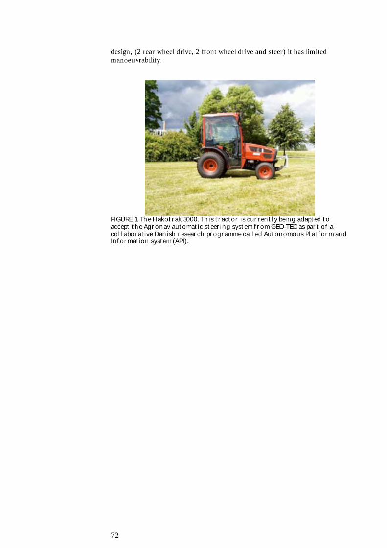
72
design, (2 rear wheel drive, 2 front wheel drive and steer) it has limitedmanoeuvrability.
FIGURE 1. The Hakotrak 3000. This tractor is currently being adapted toaccept the Agronav automatic steering system from GEO-TEC as part of acollaborative Danish research programme called Autonomous Platform andInformation system (API).

73
TABLE 1. The technical requirements for the small conventional tractorPower 20 - 30 hpEngine DieselSpeeds Infinitely variable within 3 ranges, hydrostaticControls Mechanically operated hydrostatic
Electrically operated hydrostaticWheels Four wheel drive
2 wheel steeringChassis Medium ground clearanceImplementmounting
Front three-point linkageRear three-point linkage
1.6.2 Portal tractor
The small portal tractor will have to be completely fabricated as no knowncommercial examples exist. It will be highly manoeuvrable as it will be 4-wheel drive and 4-wheel steer, which will greatly help the control algorithmswhen accurate positioning is required. It should be capable of carry a range ofimplements that will be centre mounted within the portal frame of the tractor,such as the mechanical weeding tool. A good example of such a vehicle wasdesigned and built by two Master of Science students (Madsen and Jakobsen)at the Danish Technical University in 2001 and is shown in figure 2.
FIGURE 2. Small portal tractor from the Danish Technical University
The larger portal tractors are produced in great numbers in Japan, forworking in paddy fields. They have the advantage of being designed and builtfor the agricultural environment, light weight, high ground clearance and hasstandard category zero (or one) rear three-point linkage. The example inFigure 3 has 4WD, 2WS but a 4WS could be easily made by using two frontaxles.
TABLE 2. The technical requirements for the smaller portal tractorPower 10 – 15 hpEngine Internal combustion engine (Battery at the
moment)Speeds Infinitely variable wheel motorsControls Electronic interfaceWheels Four wheel drive (4WD)
Four wheel steering (4WS)Chassis High ground clearanceImplements Centre mounted

74
FIGURE 3. A Japanese, larger type, portal tractor.
TABLE 3. The technical requirements for the larger portal type tractorPower 10 – 20 hpEngine DieselSpeeds Conventionally gearedControls MechanicalWheels Four wheel drive
Two wheel steeringChassis High ground clearanceImplementmounting
Rear three-point linkage
1.6.3 Very small vehicle. (The ‘Beetle’)
This type of vehicle is probably as small as an agricultural vehicle can get(~1m), as it needs to carry enough energy for the required tasks as well asbeing able to remain mobile over cultivated soil and crop residues. Each typeof vehicle will be highly specialised and contain an integrated tool such as agrass cutter (figure 4). To achieve such a small size, very high levels ofintegration will be needed.

75
FIGURE 4. Simple schematic drawing of the beetle Existing grass cutting equipment could be modified to give the required mobility and carry the associated control equipment. This could cause problems due to the bulk of the current equipment. This vehicle is currently being evaluated for suitability of autonomous Christmas tree weeding by the authors. TABLE 4. The technical requirements for the beetle Power ~ 5 hp Engine Petrol Speeds Fixed speeds Controls Electro-mechanical Wheels Four wheel drive
Four wheel steering Chassis Very low clearance (dependant on task) Implement mounting
Integral grass cutter
1.7 Conclusions
This paper has defined a set of requirements that form the basis for a control system that should be capable of behaving sensibly in a semi-natural environment. Behaviours modes have been described as well as the philosophical approaches to the final design from a top-down approach. Graceful degradation through using redundant systems has been identified as a key element in the production of a safe autonomous vehicle. Some alternative vehicle platforms have been considered.

Bilag B
77
Proposed Systems architecture
Simon Blackmore and Spyros FountasThe Royal Veterinary and Agricultural University, Section forAgroTechnology
To be able to achieve the behaviours noted in appendix A an inherentlycomplex and sophisticated system architecture is needed. It must haveredundant systems to achieve fault tolerance and be object oriented to remainmanageable. The objects with the SA will follow the same definitions ofobject-oriented software in terms of encapsulation, inheritance andpolymorphism. Encapsulation is of most use to us as it denotes a rigid sub-system boundary that we only need to define the interface and function atthis time. Inheritance and polymorphism is a little more difficult to achieve inhardware but processing units that can fulfil the basic functions can bemodified to suit particular applications. Communication between objects willonly be as text messages that can be understood by people as well to alloweasy analysis of the system.
The system architecture presented here has been developed to accommodatethe behavioural requirements.
1.1 Background
We consider the definition of both the behaviour and the system architectureto be of paramount importance before constructing the vehicle itself. Ingeneral terms, it is a description of how a system is constructed from basicsand how the components fit together to form the whole system (Albus,1995).
Kortenkamp (1998) states that systems architecture is a set of inter-relatedcomponents organized to achieve certain goals. Every component of thesystem has to be fully understood and to the interrelationships among thecomponents has to be defined. Arkin (1998) states that behaviors are actuallythe answer to the question “What should the autonomous vehicle be able todo?” Rzevski (1995) mentions that behavior of a machine is a particularinteraction of the machine with its environment over a period of time, definedby a particular set of inputs from and outputs into the environment over thatperiod.
In general terms, at every point in time, the vehicle is faced with a variety offeasible next states to which the machine could move, and it aims to find thetransition that is likely to provide the maximum long-term benefit. Themaximum benefit may be expressed in a variety of ways- like the minimumrisk of failure, the shortest route to a destination and the maximum utilizationfactor of a given machine (Rzevski, 1995).

78
The proposed systems architecture has been designed to accommodate thebehaviors already defined. As this behavior-based system consists of anumber of different behaviors that the vehicle needs to undertake toaccomplish the desired tasks each element within the system must contributeto one of them. A short description of the proposed behaviors can be seen intable B.1.
1.2 Systems Architecture design
In order to achieve these behaviours an object-oriented systems architecturedesign was developed. To construct this design we followed the Arkin (1998)assumption that robotic architecture designs refer to a software architecture,rather than hardware side of the system.
The benefit with the proposed system architecture is that we can divide thesystem into elements or objects and we can deal with them independently.Rzevski (1995) also supports this concept. He states that the architecturedesign usually divides the product into large modules that bring together a setof conceptually related concerns, with relatively narrow interfaces betweenthem. A narrow interface minimizes the interaction between the modules itconnects to. The advantage of well-defined interfaces is that if a change hasto be made in one module during the design process, no change is needed inother modules unless the interfaces are modified. This interface definitionalso adheres to the object oriented design philosophy.
Table B.1. Descriptions of behaviour modes.Behaviours DescriptionNavigation The process of moving safely to a
required position at a given timeRefuelling A SPECIALISED FORM OF NAVIGATION
BACK TO A BASE STATIONIdle The vehicle is doing nothing. It waits for a
command to react.Implement task A behaviour that is executed by the
attached implement whilst carrying outthe assigned task.
Self-check A process that runs all the time in thebackground. It checks to see if all theparameters of the vehicle are nominal. Itkeeps a log file and reports abnormalities
Safety Consists of different layers according tothe importance of the existing situation.
Explore A behaviour that extracts informationfrom the unknown external environmentto populate the GIS.
Planning A behaviour that analyses all theaggregated information to determine theinitial waypoints.
Request to start The behaviour from power up of thevehicle and before it moves into any othermode. All systems are reset and checkedbefore continuing.
Request to stop This behaviour indicates that the systemis ready for power off. It will be a terminalbehaviour requiring that the power haveto be shut off. During this process, thevehicle may also put all the mechanicalcomponents into a safe neutral position.

79
Each object will only communicate through high level or natural languagemessages. Each message will have the capability to pass specific parametersthat are closely coupled to the particular message. This is the approach takenby a number of other researchers. (Konoglie, 1998 etc) The schematicdiagram of the proposed system architecture is shown in Figure B.2.
In the proposed systems architecture design there are two types of objects:processes and databases. Processes execute a coherent set of tasks to achievean overall goal. This could be pure processing of data, interfaced to sensorsor closed loop control. The databases store and retrieve data on demand.Each on-board process could be realized as a processor node, with onlymessages being passed between them, over a common bus. The currentobject oriented processes and databases are described here.
Request to start
Implement Task
Navigate
Explore
Safety - Self Check (tractor-implement)
RefuellingIdle
Request to stopstart stop
Planning
Figure B.1. Statediagram showing some of the behaviours and their transitions.
1.2.1 Coordinator
The coordinating process will be carried out in the farm office on a PC. (Allother processes will be realised on-board the vehicle) It is likely to be a set ofoptimisation routines that can be instigated by the farm manager. High-levelrequests can be made, such as monitor the crop in field 10 for 2 days or carryout intra-row weeding in field 5 with implement number 2. The coordinatingprogram can then allocate resources, (e.g. which vehicles to use) prepare aninitial route plan based on the GIS and develop a suggested instruction set forthe vehicle(s). The manager can then review the proposed itinerary and makeadjustments to it before it is then downloaded to the vehicle(s). Thecoordination process will also be in on-demand communication with thevehicles and show the manager the current location and status of eachmachine. A real-time video link to steer able on-board cameras would alsoallow a better understanding of the vehicle’s environment.
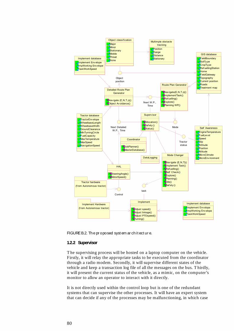
80
Tractor hardware(f rom Autonomous tractor)
Multimple obstacle tracking
PositionRangeDistanceStationary
Controltask
Implement Hardware(f rom Autonomous tractor)
Implement
Adjust speed()Adjust linkage()Adjust PTOspeed()Turning()
Implement databaseImplement Env elopeImpWorking Env elopeTaskWorkSpeed
Implement databaseImplement Env elopeImpWorking Env elopeTaskWorkSpeed
Detailed Route Plan Generator
Nav igate (E,N,T,z)()Object Av oidance()
Object position
Route Plan Generator
Nav igate(E,N,T,z)()ImplementTask()Ref uelling()Explore()Planning WP()
GIS databaseFieldBoundarySoilTy peCropTy peRef uellingStationHomeFieldGatewayTopographyCurrent positionRoadsTreatment map
Self AwarenessEngineTemperatureFuelLev elSpeedSlipAttitudePositionAltitudeMicroClimateMicroEnv ironment
Object classif icationMajorMinorStationaryMobileThreatNone
Tractor databaseTractorEnv elopeWheelbaseLengthWheelbaseWidthGroundClearanceMinTurningCircleFuelCapacityMaxTemperatureMaxSpeedNav igationSpeed
HAL
SteeringAngle()MotorSpeed()
Mode
Next W.P., Time
Next Detailed W.P., Time
Coordinator
JobPlanner()MasterDatabase()
DataLogging
Tractor status
Mode Changer
Nav igate (E,N,T)()Implement Task()Ref uelling()Self Check()Explore()Planning()Idle()Saf ety ()
Superv isor
Allocation()Saf ety ()Status()
FIGURE B.2. The proposed system architecture.
1.2.2 Supervisor
The supervising process will be hosted on a laptop computer on the vehicle.Firstly, it will relay the appropriate tasks to be executed from the coordinatorthrough a radio modem. Secondly, it will supervise different states of thevehicle and keep a transaction log file of all the messages on the bus. Thirdly,it will present the current status of the vehicle, as a mimic, on the computer’smonitor to allow an operator to interact with it directly.
It is not directly used within the control loop but is one of the redundantsystems that can supervise the other processes. It will have an expert systemthat can decide if any of the processes may be malfunctioning, in which case

81
it can then intervene. The expert system can hold a set of sensible parametervalues for comparison with what the processes are sending. It can also sendsimple requests to each process and check that it gets an expected reply. If itreceives an unexpected reply then further checks can be made to identify thesituation and take suitable actions like reset the process or shut down thewhole vehicle into one of the safety modes.
1.2.3 Mode changer
The mode changer is a process that can assess the current situation fromother processes and command each process to switch into a particular modethat can allow an appropriate overall behaviour. It may receive an imperativecommand from the coordinator, through the supervisor, for the vehicle to goto a particular position. It will check all processes to establish it is safe toswitch modes and then issue the appropriate command to each process. Anexample would be where the manager instructed the vehicle to navigate to aparticular Easting and Northing near by. If each process responded that itwas nominal, capable of accepting a new mode, and that the implement wassecured ready for transport, then each process could be configured to allowthe vehicle to navigate to the required position.
Identified messages are: Navigate(Easting, Northing, Time of arrival),Implement task(mode), Refuelling(), Self check(), Explore(), Idle(),Safety(mode), Status(), Reset(), Load program(File Name).
1.2.4 Route plan generator (RPG)
The route plan generator can accept a completed route plan from the routeplanner in the coordinator or generate its own when asked to navigate to acertain position. It will generate a series of waypoints that the vehicle willfollow to arrive at its final destination at the desired time. The waypoints willtake into account all the prior knowledge in the GIS, such as gateways,preferred paths and tracks, as well as obstacles such as fences, ditches andpublic roads. At this stage of the planning it is assumed that the vehicle willtravel on the straight line between the waypoints, so careful positioning iscrucial if the vehicle is to stay on a narrow curving track. These series ofpoints will be optimised for efficiency of the task in hand (minimum distancewould be one criteria), such as to provide the best route to start at a gateway,go down every row in a field and come back to the gateway, avoiding theknown obstacles. This route plan is predetermined before the vehicle movesand includes the estimated time of arrival at each waypoint, knowing the starttime, end time and distance to be travelled. If the arrival time at the targetposition computes to unrealistic speeds for the vehicle then a warning will begiven to the operator. The control processes will not allow the vehicle to beoperated outside predefined limits stored in the vehicle database.
1.2.5 Detailed route plan generator (DRPG)
The detailed route plan generator initially calculates a series of detailedwaypoints linearly between the waypoints from the RPG at a set distanceapart and sends steering and speed messages to the hardware abstractionlayer to move towards the next target position. As the vehicle gets to within acertain distance from a detailed waypoint, it switches to the next one in the

82
series. This process will continue until it reaches the next waypoint, unlessthere is an obstruction in the way.
If an object is sensed within a predefined range and bearing of the vehicle,then the DRPG will stop the vehicle and wait. If the range and bearing of theobstacle changes, then the DRPG will consider it to be a mobile obstacle andwait for it to move outside the safety range and resume its navigation. If theobstacle moves towards the vehicle then it will be seen as a threat and warnthe mode changer. If the object appears to be stationary, then its estimatedboundary will be entered into the GIS and the vehicle will try tocircumnavigate the obstruction.
An obstacle will be deemed an obstruction if it is likely to interfere with themovement of the vehicle or attached implement. If an obstacle is sensed bythe obstacle tracking processes to be within the working safety envelope,(derived from the tractor envelope in the tractor database and the implementenvelope from the implement database) a new detailed waypoint will begenerated to take the vehicle towards the next waypoint but at a safe distancefrom the obstacle. At this stage, the DRPG does not know the size or theextent of this unforeseen obstacle, so it must rely on the sensors to estimatethe distance and plan the next detailed waypoint accordingly and update theGIS for future reference.
1.2.6 Multiple obstacle tracking
This process runs in parallel all the time with the other processes and usessensors to search the local environment around the vehicle for any obstacles.It can estimate the range and bearing (relative to the vehicle) of a number ofobstacles within its sensing range and make a special note of the nearest oneand passes this to the DRPG and the safety process. (not shown in thediagram).
1.2.7 Object classification
The navigation process described so far has assumed a two-dimensionalworld, i.e. all obstacles are of infinite height, as is the tractor and implement.The object classification process may be needed to deal with three-dimensional objects interacting with the three dimensional vehicle. If there isa small obstacle (e.g. a small stone) in the way, can the vehicle go over it, orshould it go round? This complex issue would need a separate model of thetractor and implement.
1.2.8 Hardware abstraction layer (HAL)
The hardware abstraction layer object receives the bearing and speedmessages from the DRPG and then implements it on the physical platform. Itwill use an inverse kinematic model to determine the steering angles andwheel speeds before controlling the actuators. Each actuator will also have atransducer to measure the actuator to ensure accuracy. Closed-loop feedbackwill be used at a number of levels to ensure reliability, but all loops will bewithin the HAL object (apart from the GPS messages) as the stability ofclosed loop feedback requires fast responses which cannot be guaranteed overthe bus. As the vehicle is encapsulated within the HAL object, no process canget direct access the vehicle control system unless it goes through the HAL.
83
1.2.9 Self awareness
The self-awareness process also runs parallel and independently all the time.A wide range of sensors on the vehicle supply information about the vehicleand implement hardware components such as position, attitude, enginetemperature, fuel capacity and implement logistics. A number of othersensors provide information related to local environment such as altitude, airspeed and air temperature from a mobile weather station. All of these data areused to update the GIS database and to send messages to the safety processto decide if there is a need to shut down in adverse weather conditions orunusual situations, like if the vehicle turns over or gets stuck in mud.
1.2.10 Implement task
The implement task process is highly specialised to the particular activities ofthe implement. It gets data about the implement from the implementdatabase and has control over the whole vehicle whilst active. Examples of atask could be mechanical weeding, selective harvesting etc.
1.2.11 Tractor database
Contains information about tractor dimensions, wheelbase length and width,ground clearance, minimum turning radius, fuel capacity, maximumtemperature, maximum speed, navigation speed as well as any otherparameters considering important for the autonomous vehicle.
1.2.12 Implement database
Contains information about implement dimensions, implement-workingdimensions, task working speed as well as any other parameters consideringimportant for the implement task.
1.2.13 GIS database
The geographic information system (GIS) is the main database to store allthe spatially related data. Earl, R., Blackmore, S. et al (2000) state that theGIS is essential for generating the field operations maps for autonomousvehicles. GIS database can contain information from an asset survey,provides all the permanent spatial attributes of the field, pertinent to fieldoperations, transient data, provides attributes of a field that change during thegrowing season, e.g. crop structure and soil nutrient status and fieldoperations maps.

Bilag C
85
General motivation of usingautonomous vehicle systems
Spyros Fountas and Henrik HaveThe Royal Veterinary and Agricultural University, Section forAgroTechnology
Agriculture, horticulture and forestry have in the past benefited from asuccession of technological developments that have brought greaterproductivity and economic efficiency. Historically, the emphasis of thesedevelopments has been on the mechanisation of operations to increase workrates achievable by individual operators through the use of larger, morepowerful, machines. Today, however, the newer information basedtechnologies seems to enable reliable autonomous field operations to be viable(Earl, 2000). This may make small-scale machinery an interestingalternative.
There are many reasons to justify the use of small autonomous vehicles. Themain one may be to replace the heavy big tractors and machinery, which maydamages the soil, and moreover requires large energy inputs. According toGrath (1997) light machinery compared to the conventional have advantagesin:
• Lowered soil compaction• Lower energy consumption• Less influence from weather• Increased yield• Increased permeability for water• Less risk for prolonged periods with surface water• Increased quality of seed bed.
1.1 Vehicle efficiency and costs
Autonomous machines differ from present machinery in many ways. Theycan work for longer hours than manned machinery, they are less susceptibleto weather and soil conditions and may have better utilization, which alltogether have considerable effects on costs and environmental consequences.
1.1.1 Machinery Utilisation
Operation of common manned machinery is in most cases restricted bylabour availability (often only 5-6 hours a day on average), unsuitableweather, soil and crop conditions (up to 60 % of the time) and machinerydown time (about 3 %). This means that presently used machinery only canbe operated about 10-20 % of the total time.

86
If the labour restriction to a large extend can be removed this means thatmachinery utilisation may be increased up to 3-4 times. Additionally, if anautonomous machine is less sensitive to adverse weather conditions we canfurther increase the machinery utilisation further.
1.1.1.1 Machinery costs
A survey by Poulsen et al. (1997) of 500 full time farms in Denmark showedthat on average the largest part of the total labour and machinery costs wasthe labour costs (31%), followed by machinery depreciation (21%), interest(18%), and maintenance (16%) and energy costs (5%). A shift toautonomous machines would give a major reduction in the labour costs andalso a consider reduction because of better machine utilisation. However,high initial investment costs of autonomous systems may work in the otherdirection.
1.1.1.2 Operator limitations
Often the rate and quality of fieldwork are limited by the skill of the operator,as he has to make steering adjustments continuously while maintaining theattached implement at some level of acceptable performance. Althoughadvances have been made in tractor and cab design to improve operatorconvenience and comfort, increased speeds, power and machine widthsrequire the operator to be more attentive to the driving function, often at theexpense of reduced equipment performance. The need to relieve him isperhaps the most frequently cited reason for the need of a vehicle guidancesystem (Wilson, 2000).
Kondo and Ting, (1998), states that even though many agriculturaloperations have been mechanized, there are still many laborious andmonotonous tasks that are not suited for human beings, but require someintelligence to perform. Additionally, the availability of the farming workforceis decreasing. Compared with many other sectors, agriculture and forestry areless attractive for the younger generation. This means that the supply ofhuman resources for farming may continue to decrease in the foreseeablefuture. The development of intelligent vehicles can serve to preserve somefarming expertise. As a consequence to labour shortage, labour costs arerising, especially to highly skilled people.
Another aspect is avoidance of operator health problems from dusts andchemicals, which today is limited by various precautions as inconvenientbreading filter and skin protecting devices.
1.2 Environmental impact
The most important environmental factors affected by a shift to smallautonomous machines are soil compaction, energy savings, emission andleaching of pesticides and nutrients.
1.2.1 Soil compaction
Even though, many tractors are fitted with broad tyres , which producing lesscompaction in the topsoil, there is always a consequential problem for asevere deep compaction under the topsoil. According to numerousinvestigations this is beginning to take place when axle loads exceeds 6 ton.

87
Fear is accelerated if we bear in mind that the latest tractors with attachedimplements can weigh up to 18 tons.
Schønning et al. (2000) states, that deep soil compaction will in practice bepermanent and cannot be repaired by natural processes neither by knowngrowing processes. Permanent yield loss has been measured to 3-5%. Inreality yield loss up to 15% may be expected.
According to Håkansson (2000), soil compaction increases the need of tillageas well as the draft of tillage implements. Therefore soil compaction increasesthe costs, the energy requirement as well as the environmental effects oftillage. Various investigations he refer to has shown, that this increase may be300 % or more, when heavy machinery is operated with single wheelconfiguration in wet soil condition, while it may be insignificant when thesame machinery is operated with double wheel configuration in dry soilconditions.
Already Nielsen et al., (1977) in their motivation for researching possibilitiesfor development of a master and slave tractor system mentions versatility andavoiding deep soil compaction as reasons for using smaller tractors
1.2.2 Energy savings
Another factor of significant importance is the reduction of energy inputs. Ithas been stated by many researchers , that up to 80-90% of the energy thatgoes into traditional tillage, is required for repairing the compaction causedby the large tractors. Another factor is, that the heavy equipment uses a quitelarge amount to.
1.2.3 Site and plant specific treatment
In agriculture new technology is being developed for site and plant specifictreatments. This technology uses many technological improvements in thearea of electronics, computers and sensors. Global position system (GPS)provides precise satellite-based information on the location of various soiltypes, plants and machinery. Remote sensing devices offer the potential ofprecise mapping of soil and crop conditions. Direct sensing technology canmonitor ambient field conditions at fixed location. Electronic control systemsfacilitate precise placement of measured quantities of seed, fertiliser,herbicides and water (Blackmore, 1994). Additionally, developments incommunications and computers provide the basis for rapid transfer of data.
Together with this spatially management strategies are being developed,which attempt to approach the varied agronomic operations that take place,starting with primary tillage and ending with crop harvesting, (Earl, 2000).
The mentioned processes are diverse in type including maps of fieldoperations and final yields, remotely sensed images and records of actualtreatment. When agronomic control functions are combined with navigationsystems for automatic guidance, large data exchange and processingrequirements result such that conventional analogue systems must beexchanged for electronic systems. The majority of the data and informationrequired for autonomous field operations are position and time related. Theuse of the Geographic Information Systems (GIS) that appears pivotal to the

88
development of an integrated approach that may ultimately provide the basisfor implementing autonomous field operations.
Being able to incorporate all of these new technologies in agriculture, leads toa new scale approach. Presently the mostly used strategy is the field scaleapproach, where each field gets its specific treatment. The next strategy is thesub-field approach, where each sub-field of certain homogeneity gets itsspecific treatment. The future approach may be the plant scale strategy,which is called “phytotechnology” by the Japanese.
The site or plant specific treatments being possible by this technology meansthat blanket approach of herbicide and fertilizer applications on the wholefield may be replaced by applications adapted to the local requirements andreduce the amounts used considerable. By doing that, we will move a longstep towards sustainable and ecological agriculture.
1.2.4 Added value
Apart from the above advantages the data collected by the sensor systems ofautonomous or precision machinery or may be used to improve managementin other ways, i.e. estimation of crop quality and yield values for salesdecisions as well as identification of problem areas or plants of the field.