Embed Size (px)
Citation preview
Autonomous Navigation in Crowded CampusEnvironments
Z. J. Chong∗, B. Qin∗, T. Bandyopadhyay‡, T. Wongpiromsarn‡, E. S. Rankin¶,M. H. Ang Jr.∗, E. Frazzoli§‡, D. Rus§‡, D. Hsu∗, K. H. Low∗
∗ National University ofSingapore,
Kent Ridge, Singapore
‡ Singapore-MIT Alliance forResearch and Technology,
Singapore
§ Massachusetts Instituteof Technology,
Cambridge, MA., USA.
¶ DSO NationalLaboratories,
Singapore
Abstract—This paper considers autonomous navigation incrowded city environments. An autonomous vehicle testbed ispresented. We address two challenges of pedestrian detectionand GPS-based localization in the presence of high-level build-ings. First, we augment the localization using local laser mapsand show improved results. A pedestrian detection algorithmusing a complementary vision and laser system is proposed.We implement this algorithm in our testbed and evaluate itsperformance using purely off the shelf components and opensource software packages provided by ROS. We also showhow utilizing existing infrastructural sensors can improve theperformance of the system. Potential applications of this workinclude fully automated vehicle systems in urban environmentstypical in megacities in Asia.
I. INTRODUCTION
One of the long-standing research activities in robotics hasbeen towards increasing the level of autonomy in both mannedand unmanned systems. In transportation systems, automationhas been employed, for example, in traffic light managementand congestion avoidance services and has attracted numerousresearch interests in the transportation science and logisticscommunity. Intelligent vehicle/highway systems (IVHS) tech-nologies have also been developed to enhance operationalsafety and efficiency [14].
In this paper, we focus on putting more autonomy into thetransport vehicles to deal with the problem at a more locallevel. Interests in autonomous driving, especially in urban en-vironments, were largely stimulated by the launch of the 2007DARPA Urban Challenge (DUC). In this competition, theautonomous vehicles have to navigate, in a fully autonomousmanner, through a partially known urban-like environmentpopulated with (static and dynamic) obstacles and performdifferent tasks such as road and off-road driving, parkingand visiting certain areas while obeying traffic rules. As theemphasis of the competition is geared more towards militaryapplications, the vehicles have to be fully self-contained inevery aspect including sensing, perception, computing, power,and control. Although this leads to an elegant setup, thesituations encountered in DUC do not closely represent thosefaced in a real-world crowded city like Singapore, London,etc. In addition, the cost of hardware components on theseautonomous vehicles is extremely high, making them imprac-
tical to be employed in social or commercial applications. Themajority of the cost comes from expensive, high-performancesensors (e.g. Velodyne LIDAR) and localization units (e.g.Applanix Intertial Navigation System) needed so that the ve-hicles can effectively handle all the possible (even adversarial)environments they may encounter.
This paper focuses on crowded city situations where au-tomation can significantly improve the throughput as comparedto on ground human decisions. As opposed to adversarialenvironments faced in military applications, city environ-ments faced in social or commercial applications are typicallyequipped with infrastructure including cellular networks, traf-fic cameras, loop detectors and ERP (Electronic Road Pricing)gantries. In addition, the detailed road network and manyfeatures of the environment in which the vehicles operate canbe obtained a priori. In fact, autonomy in transport vehicleshas been attained at various levels of interaction with the in-frastructure. Systems that are driven with heavy infrastructuredependence such as mono-rails typically require significantsetup and are more suitable for a fully controlled environmentsuch as warehouses and docks. FROG (Free Ranging on Grid)Navigation Systems1 is an example of such heavily structure-dependent systems and has been deployed for container han-dling operations in factory sites. Their system consists of ateam of autonomous vehicles and a centralized supervisorysystem. The autonomous vehicles localize themselves usingmagnets on the floor and GPS for point to point navigationand use laser and sonar for obstacle avoidance. An advantageof this approach is that the global viewpoint of the environmentcan be obtained while the main disadvantages include delayedinformation, communication burden and cost of specializedinfrastructure setup.
On the other hand, Google driverless car, for example,is fully autonomous [9]. Their converted Toyota Prius usescameras to detect traffic lights and radars to detect pedestrians.Their autonomous navigation also relies on laser range finders,cameras, radars, inertial sensors and high-detail maps. Anadvantage of these fully autonomous systems is the abilityto handle dynamic and adversarial scenarios. However, as
1http://www.frog.nl/

opposed to heavily structure-dependent systems, only limited,local viewpoint can be obtained as on-board sensors on eachvehicle have the same limitation of limited viewpoint andocclusion by urban structures and other vehicles. Each vehiclealso bears the burden of sensing and perception. Additionally,being fully autonomous and self-contained comes with a heavyprice tag.
In this paper, we investigate the integration of the heavilystructure-dependent and the fully autonomous approaches inorder to build an autonomous vehicle system at reasonable costas well as keep the high level of autonomy even in a crowdedscenario. As an initial step, we focus on campus environments.We exploit an abundance of infrastructural sensors available tothe road network that can provide very important informationabout the presence of other entities on the road in real time.This information can help in planning collision-free optimaltrajectories for each vehicle beyond visual range. Exploitingthe infrastructure also helps reduce the sensing burden onthe vehicle and reduce the cost of the vehicle, making suchsystems more economical and accessible to normal people.The main contributions of the paper are the following.
1) Typical localization techniques heavily depend on GPS(Global Positioning System). These techniques do notwork when dealing with high-level buildings in cityenvironments. We augment the localization using locallaser maps and show improved results.
2) We implement a more robust pedestrian detection systemusing a complementary vision and laser system. Weshow that such a set up works well even for a movingvehicle.
3) Our approach is to incorporate existing infrastructuralsensors whenever possible into the motion planningof the autonomous vehicle. To demonstrate the setup,we show a scenario incorporating the infrastructuralsensors that significantly improves the performance ofthe vehicle operation.
The remainder of the paper is organized as follows. Anoverview of our testbed is provided in Section II. SectionIII describes our dynamic obstacle detection component and,in particular, the pedestrian detection algorithm implementedin our testbed. Its performance is evaluated, both for singleand multiple pedestrian cases. The localization and navigationcomponents are described in Section IV. Section V describesthe role of infrastructural sensors in our system. Finally,Section VI concludes the paper and discusses future work.
II. AUTONOMOUS VEHICLE TESTBED
Our autonomous vehicle testbed is a Yamaha G22E golf carmounted with various sensors (Fig.1a). It was modified andequipped with actuators to achieve drive by wire capabilities.Two servo motors are used to control the steering angle andamount of brake applied separately. Since it is an electricvehicle, the throttle control is readily accessible through avarying PWM voltage signal that can be regulated by alow level controller. To fulfill the power requirement for awide variety of sensors, a 1350W inverter was used. For the
sensors, a wheel encoder is fitted at the left front wheel.The steering angle and brake are inferred implicitly from themotors encoder. To receive GPS signal, Ublox EVK-6R isused. The module comes with Enhanced Kalman Filter to givean estimate of global location using integrated data input fromwheel encoders tick count and onboard gyroscope. The mainsensors are the laser range finders that consist of two SICKLMS 291 and Hokuyo UTM 30LX. The SICK lasers have arange of 80 m with 180◦ field-of-view (FoV). The Hokuyosensor, on the other hand, has 270◦ FoV with 30 m range. Anoff the shelf webcam is fitted on one of the SICK lasers toprovide visual feedback and to perform vision processing.
Software Architecture: We have developed a modularsoftware architecture for ease in incorporating additionalfunctionality without modifying the core system. The systemhas been integrated into ROS (Robotic Operating System),which provides a standard form of communication amongdifferent software modules [11]. The main modules that havebeen implemented on the current system include perception,mapping-and-prediction, localization, planner and controller asshown in Fig. 1b.
The perception module takes as an input the raw senseddata from the sensors. Detection and tracking algorithm is thenapplied to extracted features (e.g., pedestrian and other movingand stationary objects) from the raw sensed data. As discussedin Section V, the sensors we have utilized include not onlyonboard cameras and laser range finders but also infrastructurecameras installed, for example, at an intersection. The datafrom these infrastructure cameras are transmitted through aWiFi network. To reduce the amount of data that needs tobe transmitted, the raw sensed data may be processed so thatonly important features (e.g., other vehicles and pedestriansapproaching the intersection) are transmitted.
The mapping-and-prediction module maintains the globalmap of the environment in which the system is operating.In addition, it predicts the motion of moving objects suchas pedestrians. The localization module incorporates the datareceived from the GPS (Global Positioning System), IMU(Inertial Measurement Unit), laser range finder and vehicle’sodometer to provide an estimate of the current state (position,velocity and heading) of the vehicle.
The planner module is responsible for computing anobstacle-free path, satisfying certain traffic rules, to the goal. Inthe case where the user is onboard, the goal may be specifiedas the destination through the user interface. Alternatively,the scheduling system that computes the pick-up and drop-offposition for each autonomous vehicle may send the origin anddestination to the system through a cellular network. Finally,the controller module is responsible for computing the actuatorcommands, including the speed, gear and steering angle, tothe physical actuators so that the vehicle closely follows theplanner-generated path.
III. DYNAMIC OBSTACLES DETECTION
For autonomous navigation, we need to pay special attentionto dynamic objects, like pedestrians and other vehicles on the
2

Localization
Perception
Mapping and Prediction
Planner
Controller
gear, speed, steering angle
path
Camera
LIDAR
Infrastructure
GPS
IMU
Odometry
User Interface
Scheduling System
destination origin/destination
vehicle state
global map
vehicle state
vehicle state
local map
Vehicle
(a) System Testbed (b) System ArchitechtureFig. 1. Autonomous Vehicle Testbed
(a) (b)Fig. 2. Pedestrians and other dynamic vehicles need to be detected andhandled. (a) NUS campus road, (b) Golf-cart operating in the presence ofpedestrians
road in addition to static environmental features like kerbs,drains, traffic lights, etc (Fig.2). Usually the presence ofstatic objects are known a-priori from a traffic database orbuilt during and initial phase in an offline manner. However,dynamic objects on the road can only be handled while theautonomous vehicle is driving. Pedestrians, as a key factor in acampus environment, deserve more attention. On-board cam-eras are one of the most effective ways of identifying objectsin the environment. However, the computation requirementand dependence of ambient light conditions limit their utility.Alternatively, laser based approaches can detect the presenceof an object more reliably but have problem disambiguatingdifferent types of objects. In our project, we built an onboardpedestrian detection system by hierarchical fusing of a single-layer LIDAR and a simple off the shelf webcam. We combinethe advantages of LIDARs in detecting an object with thesimplicity of disambiguating objects from the camera images.It proves to be fast, computationally efficient and robust in ouroperations.
Significant research has been done on pedestrian detectionand tracking with LIDARs and vision. The LIDARs pro-vide accurate position information of scanned points in thesurroundings, which will be segmented, clustered, and thenclassified into different objects. Pedestrians can be extracted
with certain criteria or features, such as static features of shapeand size founded in [5], [10], or dynamic features of gaitfounded in [15], [2], and so on. These algorithms performwell with multiple LIDARs placed off-board and in relativelystructured environment, but would probably fail in real urbantraffic, due to severe occlusion and complex surroundings. Inthe final analysis, limitation of these algorithms comes fromsparsity of information of LIDARs. The idea of multi-sensorfusion arises to counter this limitation. The most common typethat can be found is a combination of LIDAR and camera.While some related algorithms have been introduced in [4],[6], few of them are suitable to autonomous vehicles, withconsiderations to the demanding working environment. Analgorithm similar to our approach is proposed in [3]. It dependson a four-layer LIDAR to track pedestrians and do preliminaryclassification, and then use camera to refine the classificationbelief. In our project, a similar algorithm is proposed. Whilewe also rely on a single-layer LIDAR to track objects, wedo not try to classify them in this part, but leave that to thefollowing part of vision verification. Our algorithm provesfast, computationally efficient, robust in operation, and easyto implement.
A. Pedestrian detection algorithm
In our implementation the moving object tracking is realizedwith a single-layer LIDAR. While the approach is generalto any dynamic object, like vehicles, pedestrian and otherobjects, we take the pedestrians as a representative class totalk about in details in this paper. Fig.3 shows the flow ofthe algorithm while, Fig.4 shows the result of the detectionalgorithm for a single data frame. The algorithm runs intwo phases, pedestrian candidate detector and pedestrianverification.
Pedestrian candidate detector: The LIDAR data is seg-mented and clustered based on their position and relative
3

(a) Camera Input (b) Laser Input (c) laser based image segmentation
(d) HOG classifier output (e) Robust pedestrian detection (f) Track of single pedestrian.Fig. 4. Pedestrian detection module
Fig. 3. Pedestrian detection module.
velocity (Fig.4b). Potential candidate clusters for pedestriansare filtered out based on their size and velocity. We use asimple linear velocity model in our implementation. Howeveradvanced model checks could also be used for higher accuracy.In fact keeping a more relaxed and conservative filter decreasesthe rate of false negatives in the subsequent pedestrian verifi-cation phase.
Pedestrian verification: In this part, we use a commonwebcam to verify whether extracted objects are pedestriansor not. Extrinsic calibration of webcam and LIDAR is donebeforehand. These candidates are projected onto certain areas
of webcam image correspondingly. The whole image is thencropped into several smaller sub images (Fig.4c). Since onlya small number of sub-images are processed, we decrease thecomputational time in image processing. The vision verifi-cation algorithm used here is histogram of oriented gradientobject detection (HOG). In this work, a default trained peopledetector Support Vector Machines (SVM) from OpenCV waschosen. To enable fast verification, GPU accelerated HOGalgorithm was used. HOG classifier identifies each sub imagecontaining pedestrians (Fig.4d) and we label the LIDARtracks accordingly. This helps us in avoiding running visionbased pedestrian detectors on the whole image (Fig.4a,e) andsignificantly reduces the computational load. The reducedcomputation allows us to run such detectors in real time onthe vehicle.
Note that the pedestrian detection allows us to improve themotion planning for the autonomous vehicles by reasoningabout the motion models of the pedestrian obstacles. In thecase of false negatives due to vision errors and FoV limitations,the pedestrian clusters are still tracked by the laser, treated asa generic dynamic object and avoided accordingly.
B. Performance evaluation
Single pedestrian detection: Fig.4 shows how this systemdetects and track a single pedestrian. Fig.4(f) shows the trackof this pedestrian. At first, the pedestrian gets tracked byLIDAR, and labeled as a dynamic object shown in white. Afterit enters the FoV of webcam, it gets verified as a pedestrian
4
and the track turns green. Other potential dynamic objects inthe image are correctly rejected.
Multiple pedestrian detection: Fig.5 shows the result ofour pedestrian detection module during an segment of anautonomous run. Fig.5a shows a snapshot of a typical scenewith multiple pedestrians. We see that when the pedestrians aretoo close to each other the laser signatures get merged and theyare detected as a single cluster. However, in the view of motionplanning it does not matter how many actual pedestriansare close by, our autonomous vehicle avoids the pedestrianseffectively. In the test, most pedestrians got detected, whetheras an individual, or as a group, making safe autonomousdriving of our vehicle. Frequency of this detection system isup to 37Hz, limited by scan frequency from LIDAR. Rangeof effective detection is about 14 meters, limited by resolutionof webcam. Our system works well within 14 meters withsystem precision around 0.8, From Fig.5b, Vision verifica-tion improves precision of detection system based on laserextraction. Even when much noise exists, as what happenedat the distance between 4 to 6 meters in our collected data,while precision of laser part is only about 0.20, vision partimproves it to about 0.80. Note that most of the errors if anyin detection as shown in Fig.5b are corrected at around 4m,at which distance the autonomous vehicle is able to come toan emergency stop under the influence of high frequency lowlevel obstacle avoidance. We will be re-visiting this detectionrate at higher speeds once we implement the system on a fastervehicle.
IV. LOCALIZATION AND AUTONOMOUS NAVIGATION
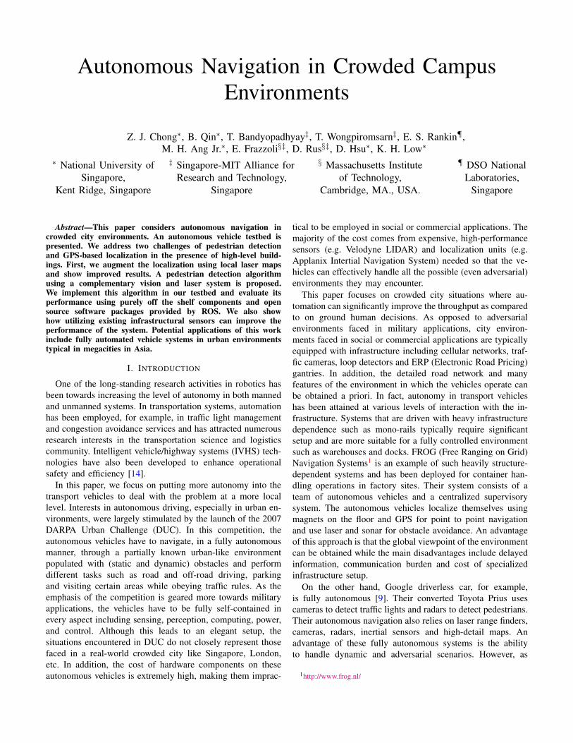
Most of the popular approaches in autonomous navigationoutdoors depend heavily on GPS based localization. In factthe DARPA challenge was based on GPS based waypointsas input. However GPS is not very reliable in urban areasdue to multi-path, limited satellite view in tall sky-scrapers.Such a scenario is shown in Fig.6a. A cloudy sky coupledwith tall buildings can attenuate the GPS signals, resulting inerroneous localization as shown by the GPS track in Fig.6b. Asthe vehicle moves, its GPS erroneously estimates the vehiclelocation inside buildings and a pure GPS based localizationand control could lead to failed navigation.
Interestingly one of the main reasons of GPS limitation i.e,the proximity of buildings, itself provides a good opportunityto utilize range based localization algorithms. In our work weuse the laser based maps to augment in regions where GPSunderperforms.
A. Localization
We compare our approach with the popular approach usedby most of the participants successfully in the DARPA Ur-ban Challenge of using the integrated GPS + Inertial basedbayesian estimate. While such an approach can help localize ina-priori unknown environments as was the case in the DARPAChallenges, the presence of cloudy sky and high rise buildingsgive very poor estimates.
(a) (b)Fig. 6. Bad GPS with integrated gyro based odometry
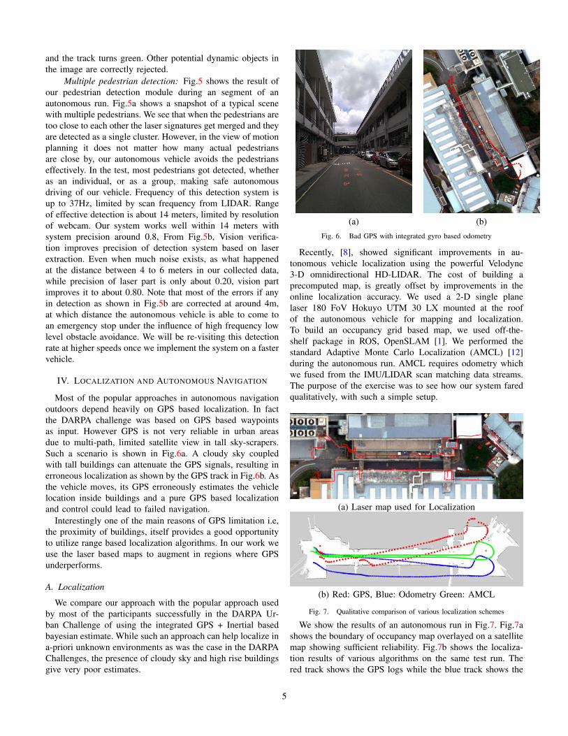
Recently, [8], showed significant improvements in au-tonomous vehicle localization using the powerful Velodyne3-D omnidirectional HD-LIDAR. The cost of building aprecomputed map, is greatly offset by improvements in theonline localization accuracy. We used a 2-D single planelaser 180 FoV Hokuyo UTM 30 LX mounted at the roofof the autonomous vehicle for mapping and localization.To build an occupancy grid based map, we used off-the-shelf package in ROS, OpenSLAM [1]. We performed thestandard Adaptive Monte Carlo Localization (AMCL) [12]during the autonomous run. AMCL requires odometry whichwe fused from the IMU/LIDAR scan matching data streams.The purpose of the exercise was to see how our system faredqualitatively, with such a simple setup.
(a) Laser map used for Localization
(b) Red: GPS, Blue: Odometry Green: AMCL
Fig. 7. Qualitative comparison of various localization schemes
We show the results of an autonomous run in Fig.7. Fig.7ashows the boundary of occupancy map overlayed on a satellitemap showing sufficient reliability. Fig.7b shows the localiza-tion results of various algorithms on the same test run. Thered track shows the GPS logs while the blue track shows the
5

(a) Sample pedestrian detection (b) Pedestrian precisionFig. 5. Pedestrian detection from an autonomous run of our testbed.
location of the vehicle using the odometry alone. The greentrack is computed by the AMCL algorithm. We see that for thepurposes of our sample test run, our laser based localizationwas sufficient. This is also borne out by various runs of ourautonomous vehicle one of which is shown in Fig.7b, in thepresence of temporary occlusions and other dynamic vehicles.
B. Cost based Navigation function
Fig. 8. Navigation module of the autonomous vehicle
Fig.8 shows the structure of our navigation module. Duringeach run, the vehicle maintains its own map based on rollingbasis, with the vehicle centered on the map. A map of 50mx 50m with a grid cell size of 0.2m is maintained at all time.Each cell in the map can have a 1 byte value. Initially, thecells in the map are marked as unknown with a value of 255.Whenever an obstacle is observed, the map is updated witha cost value of 254, with the cells now marked as obstacles,the cost is propagated radially outward with an exponentialfunction. At the low level, speed and steering control areseparated. For the speed control, the vehicle considers thefollowing input before planning for next action: the averagecost function that is present within a defined area in frontof itself and the curvature of the path. To ensure stability, aconservative approach is utilized. First, an exponential functionis used to calculate the safe speed given the steering angle ofthe golf car. Then, from the normalized average cost along theprojection of the golf car within a fix distance, another safespeed is obtained. Between these 2 values, the minimum one ischosen as the final set point for the speed. The implementationof waypoint follower uses pure pursuit control [7]. Since thegolf car’s maximum speed is limited to 2 m/s, the look-aheadvector is fixed to 3 meters.
V. EXPLOITING INFRASTRUCTURE SENSORS
An important feature that distinguishes urban environmentsfrom those considered in military applications is the tech-nological advances that we can exploit in order to increasesafety and efficiency of the system without imposing muchadditional cost. Consider, as an example, the scenario wherean autonomous vehicle has to traverse an intersection. In manycases, other vehicles approaching the intersection from otherdirections may not be detected properly by the onboard sensorsdue to limited sensing coverage and occlusions caused bystructures and other environmental features. In [13], the au-thors mitigate this problem by using two pointable long-rangesensors and propose a methodology for computing the optimalangles of the sensors to maximally cover relevant unobservedregions of interest. A method for detecting occlusions is alsopresented. A phantom vehicle is then placed in the occludedarea, leading to a safe but potentially conservative result.
In this work, we consider utilizing infrastructure cameras in-stalled, for example, at an intersection, rather than completelyrelying on the onboard sensors. These infrastructure camerascan provide information about whether there are pedestrians orother vehicles approaching the intersection. The informationcan then be transmitted through a WiFi or cellular network. Anadvantage of this approach is that more accurate informationcan be obtained as the infrastructure cameras may be mountedto avoid occlusions. In addition, as the number of autonomousvehicles in the system exceed the number of intersections, thecost can be substantially reduced. In fact, in many moderncities, cameras are already installed at many intersections todetect traffic violations. Hence, this approach may incur almostno additional cost.
A. Avoiding Unobserved Pedestrians
To show the effect of additional information, we simulatean infrastructural sensor as a wifi-node broadcasting specificinformation. The infrastructural camera detects the presenceof pedestrians and gives a binary information to the golf-cartwhether there are pedestrians about to cross the road or if theregion is pedestrian free. Currently we are not building modelsof pedestrian intentions to analyze whether the pedestrian isfacing the road or whether s/he is just waiting rather thantrying to cross the road. Any pedestrian detection would
6

trigger the autonomous vehicle to slow down in anticipationfor the pedestrian to cross the road. The rate of pedestriandetection is 5 Hz. However, since the algorithm only dependson the pedestrian detection alone and not a more detailedanalysis based on the pedestrian position and heading, it wouldalso work well with modern traffic/security cameras operatingaround 1Hz.
Fig.9(a,b) show the view of the scene from onboard as wellas a mock infrastructure sensor. The detection of the pedestrianin the left of the image in Fig.9a is quite difficult due to theocclusion from pillars and railings. The autonomous vehiclehas to communicate with an existing sensor (security camera)to get more information to plan its path. The pedestriandetection is much easier in Fig.9b. The autonomous vehiclegets the pedestrian information from the infrastructure pedes-trian detector sensor and modifies its motion plan, as shownin Fig.9c. The videos of the operation can be accessed athttp://dl.dropbox.com/u/20792983/pedestrianVisual1.mp4 andhttp://dl.dropbox.com/u/20792983/pedestrianVisual2.mp4.
. . .
Ped. Sensor
V2 V1
Ped. sensing region
Ped. crossing
Looped track
Fig. 10. Simulation environment setup.
1) Control comparative experiments: Clearly, we wouldexpect to see an improvement in the navigation performancewhile incorporating the information from an infrastructuralsensor. To test the amount of improvement in a stochasticpedestrian arrival scenario, we run a control experiment insimulation as shown in Fig.10. One or more vehicles move in aloop that has a pedestrian crossing. A pedestrian detection sen-sor (i.e., a traffic camera) detects the presence of pedestriansand sends information to the autonomous vehicles V 1, V 2, . . ..Depending on the presence of pedestrians appearing in astochastic poisson process of mean rate λ = 1ped/sec.,the vehicles slow down or keep moving. The vehicles arealso constrained to maintain a minimum distance betweenthem to avoid collision. We run the experiment both fora single vehicle as well as multiple vehicles. We comparethe performance with the baseline case where there is noinfrastructural sensor and the autonomous vehicle has to cometo a stop before detecting pedestrians on road, somethingsimilar to a regular stop and yield traffic sign. We run thesimulation for various vehicle speeds and various number ofvehicles. Let Tbase be the time taken to reach the pedestriancrossing by the baseline algorithm, while Tinfra. be the samemeasure for our algorithm getting additional information fromthe infrastructure sensor. We compute the difference in thetime taken to complete each lap, as the time gained by using
the infrastructural sensor, Tgain = Tbase − Tinfra..Single Vehicle: Fig.11a, shows the plot of Tgain vs the
number of laps the vehicle completes. We see clearly thatthe cumulative time gained by using the infrastructural sensorimproves with time. We also note that such a gain is moresignificant when the vehicle moves at a higher speed. Theblue plot is the gain for vehicle moving at 2m/s while the redat 1m/s. This shows that the traffic flow at pedestrian crossingswhere the vehicles are able to move at higher speeds can besignificantly improved by using infrastructural sensors.
Multiple Vehicles: Fig.11b, shows the plot of Tgain vsthe number of laps the vehicle completes for multiple vehicles.We see that as the number of vehicles increases, Tgain alsoincreases. This is because in the baseline algorithm, eachvehicle has to stop for pedestrians whether or not they arepresent. Additionally they have to stop to maintain a minimumdistance to the vehicle in front when the front vehicle stops.The number of vehicle stops increases significantly when thenumber of vehicles increases raising the discrepancy betweenthe proposed and the baseline algorithm.Tgain is the difference in cumulative improvement in per-
formance. In a stochastic setting, Tgain varies and so althoughwe see a clear mean increase in performance, the plot is notstrictly monotonic. Moreover for the multiple vehicle scenariowe assumed that pedestrian take longer duration to completethe crossing than the car making the stop and go sequence.Hence over the long run, more often than not the lead car(Vehicle 1) takes the burden of stopping for the pedestriansshowing a smaller rate of performance improvement.
During the operation and our experimental runs, we noticedthat the infrastructure sensor rarely had any failure in detectingthe appearing pedestrians. As the detection is a boolean i.e,either there is a pedestrian or not, a very reliable detectionrate is achieved by carefully tuning the parameters of thestatic infrastructure sensor to the exact detection region. More-over, the autonomous vehicle testbed moves relatively slowlyunder 3m/s and performs a proximity test with its onboardrange sensors at a very high frequency. These two factorsin conjunction avoids any future collisions of the vehiclewith incoming pedestrians. We are currently investigating theeffects of noisy infrastructure sensor, information delay, andhigh speed vehicles for more complex scenarios.
VI. CONCLUSION AND FUTURE DIRECTIONS
We considered three main challenges in autonomous naviga-tion in crowded city environments: localization, pedestrian de-tection and limited onboard sensing capability. We showed thatin the proximity of tall buildings, popular GPS-based localiza-tion can be extremely erroneous. Odometry-based localizationwas shown to perform slightly better. In order to achieveacceptable performance, we augmented the localization usinglocal laser maps based on Adaptive Monte Carlo Localizationtechnique and showed significantly improved results. We alsointegrated the use of vision and LIDARs to achieve morerobustness in pedestrian detection and tracking. Finally, we
7

(a) Onboard camera view (b) Infrastructure camera view (c) Vehicle in operationFig. 9. Pedestrian crossing experiment
0 10 20 30 40 50−20
0
20
40
60
80
Time step
Tga
in
Vel 1m/s
Vel 2m/s
0 10 20 30 40 50−20
0
20
40
60
80
Time step
Tgai
n
Vehicle 1
Vehicle 2
Vehicle 3
(a) Single vehicle (b) Multiple vehiclesFig. 11. Improvement in traffic flow due to incorporating infrastructural sensing in simulation.
exploited existing infrastructural sensors to improve the on-board sensors visibility. The performance of the overall systemwas evaluated.
Future work targets at augmenting the current system toa fully automated campus vehicle system. To this end, weare currently investigating the use of WiFi-based localizationas a complementary approach to GPS-based and laser-basedlocalization. We also plan to incorporate pedestrian intentionsin motion planning. Implementation of high-level logics toensure that the autonomous vehicle obeys traffic rules, properlyhandles pedestrian and responds to faults and failures is alsoof interest. Finally, the system needs to be verified for safetyboth for nominal operations and in the presence of faults andfailures.
REFERENCES
[1] OpenSLAM. http://openslam.org/.[2] J. Cui, H. Zha, H. Zhao, and R. Shibasaki, “Robust tracking of multiple
people in crowds using laser range scanners,” in Proceedings of ICPR,vol. 4, 2006, p. 857.
[3] F. N. G. Gate, A. Breheret, “Fast pedestrian detection in dense envi-ronment with a laser scanner and a camera,” in Proceedings of IEEEVehicular Technology Conference, 2009.
[4] R. S. H. Zhao, “A real-time system for monitoring pedestrians,” inProceedings of IEEE WACV/Motions, vol. 1, 2005, p. 378.
[5] V. W. K. Fuerstenberg, K. Dietmayer, “Pedestrian recognition in urbantraffic using a vehicle based multilayer laserscanner,” in Proceedings ofIntelligent Vehicle Symposium, 2002.
[6] Y. Kobayashi and Y. Kuno, “People tracking using integrated sensors forhuman robot interaction,” in Proceedings of 2010 IEEE InternationalConference on Industrial Technology, 2010, p. 1617.
[7] Y. Kuwata, J. Teo, G. Fiore, S. Karaman, E. Frazzoli, and J. P.How. Real-time motion planning with applications to autonomous urbandriving. http://dspace.mit.edu/openaccess-disseminate/1721.1/52527.
[8] J. Levinson and S. Thrun, “Robust vehicle localization in urban en-vironments using probabilistic maps,” in Proceedings of InternationalConference on Robotics and Automation (ICRA), 2010.
[9] J. Markoff, “Google cars drive themselves, in traffic,” The New YorkTimes, October 9, 2010.
[10] T. H. O. Mozos, R. Kurazume, “Multi-part people detection using 2drange data,” in Proceedings of 2009 IEEE ICRA, 2009.
[11] M. Quigley, K. Conley, B. P. Gerkey, J. Faust, T. Foote, J. Leibs,R. Wheeler, and A. Y. Ng, “ROS: an open-source Robot OperatingSystem,” in ICRA Workshop on Open Source Software, 2009.
[12] D. F. Sebastian Thrun, Wolfram Burgard, Probabilistic Robotics. MIT.Press, 2005.
[13] Y.-W. Seo and C. Urmson, “A perception mechanism for supportingautonomous intersection handling in urban driving,” in IEEE/RSJ Inter-national Conference on Intelligent Robots and Systems (IROS), 2008,pp. 1830–1835.
[14] S. E. Shladover, “Potential contributions of intelligent vehicle/highwaysystems (IVHS) to reducing transportation’s greenhouse gas production,”Transportation Research Part A: Policy and Practice, vol. 27, no. 3, pp.207 – 216, 1993.
[15] H. Zhao and R. Shibasaki, “A novel system for tracking pedestriansusing multiple single-row laser-range scanners,” in Proceedings of 2005IEEE Transactions on Systems, Man, and Cybernetics-Part A: Systemsand Humans, vol. 35, no. 2, March 2005.
8