Embed Size (px)
Citation preview

Autonomous multichannel dataacquisition systemG. T. Kouroupetroglou, C. A. Caroubalos, D. N. Asimakopoulos, and N. T. Vakasis Citation: Review of Scientific Instruments 59, 179 (1988); doi: 10.1063/1.1140003 View online: http://dx.doi.org/10.1063/1.1140003 View Table of Contents: http://scitation.aip.org/content/aip/journal/rsi/59/1?ver=pdfcov Published by the AIP Publishing Articles you may be interested in The Tramp DataAcquisition System Comput. Phys. 7, 638 (1993); 10.1063/1.4823239 Dataacquisition system for a thermal desorption spectrometer Rev. Sci. Instrum. 60, 958 (1989); 10.1063/1.1140355 Inexpensive computer dataacquisition system Rev. Sci. Instrum. 56, 1972 (1985); 10.1063/1.1138407 Intelligent multichannel dataacquisition system for pulsed laser applications Rev. Sci. Instrum. 55, 204 (1984); 10.1063/1.1137717 New pulsed laser dataacquisition system Rev. Sci. Instrum. 54, 97 (1983); 10.1063/1.1137232
This article is copyrighted as indicated in the article. Reuse of AIP content is subject to the terms at: http://scitationnew.aip.org/termsconditions. Downloaded to IP:
130.18.123.11 On: Mon, 22 Dec 2014 04:48:55

Autonomous multichannel data-acquisition system G. T. Kouroupetrog!ou, Co A. Caroubalos, and Do N. Asimakopoulos
Department 01 Physics, University 01 Athens, GR 15771, Greece
N. T. Vakasis
National Defence Research Center, Athens, Greece
(Received 1 July 1987; accepted for pUblication 18 September 1987)
A flexible, general pur~ose, portable and autonomous data-acquisition system is presented. Data are stored on a mne-track IBM-format compatible digital magnetic tape recorder. The hardware allows data captur~ fro~ 1 to 16 channels and with 12-bit resolution at speeds of up to 2~ kHz, for relevant long tIme mtervals. A special buffer has been also designed to support nonmterleaved operation at the maximum transfer rates for both the analog-to-digital converter and the storage device.
INTRODUCTION
The steady growth of the amount of data generated in various experiments of physics and the increasing complexity of such experiments necessitate the processes of data acquisition and data reduction. In many applications we need a data-acquisition system with the following general specifications; (a) very simple operation, (b) autonomous and portable, (c) direct transfer of the collecting data for subsequent processing to the usual existing computer facilities of a research laboratory, (d) flexible in the changes of the collecting parameters (number of input channels, sampling rate, and input voltage ranges), and (e) data collection for relevant long time periods without loss of a single point at the acoustic frequency range.
With this paper we present a data-acquisition unit, the design of which gives the following solutions to the above specifications: (a) Its operation during the data-acquisition phase is as simple as using a home analog tape recorder; (b) It is autonomous and portable. There is no connection to a computer system during the acquisition time. The only connection is to the power line; (c) Data are stored on a ninetrack IBM-format compatible digital tape and can be read from any computer with an analogous tape unit; Cd) One can select by simple operations from: (1) 12 internal sampling frequencies of up to 24 kHz and an external clock input, (2) 1-16 input channels, and (3) input voltage ranges ± 2.5, ± 5, ± 10,0-5,0-10, and 0-2.5 V; and (e) It uses a
dedicated analog-to-digital-converter (ADC) buffer so that it can store, in any sampling rate, up to 12X 106 measurements, with 12-bit resolution and without loss of one point. Notice that the above specifications Cd) and (e) are dependent on the specific components used in the present unit. The general design philosophy of the system allows, for example, with the use of a 1600-bpi tape transport, to achieve twice the above storage capacity.
I. HARDWARE DESCRIPTION
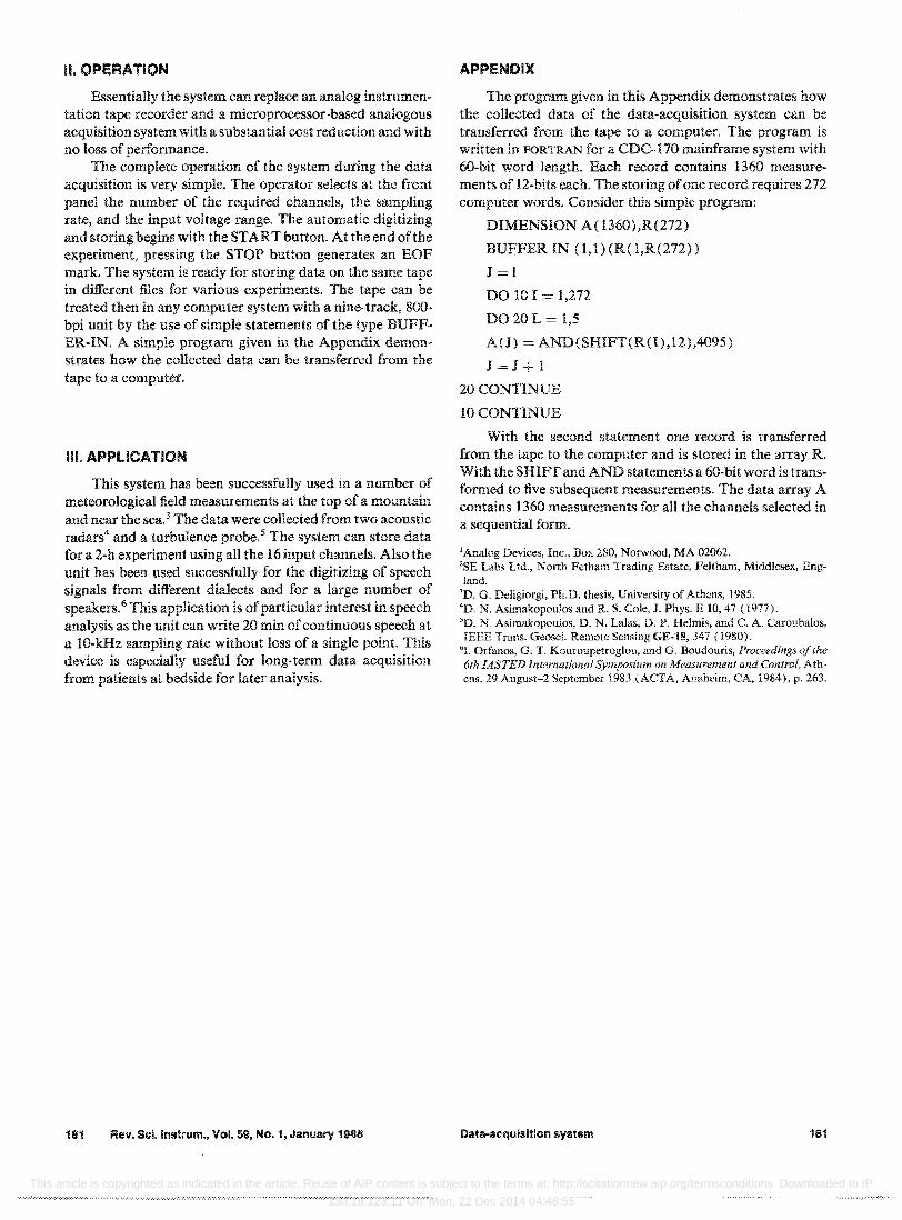
A block diagram of the data-acquisition system is shown in Fig. 1. The system consists of three main parts: 0) the analog input section with the ADC, Oi) the buffer, and (iii) the digital tape unit.
We have used the model AD363 circuit of Analog Devices l as the analog input section. This circuit includes two eight-channel multiplexers, a differential unity gain amplifier, a sample-and-hold amplifier, channel address latches, and control logic. The 16 input lines can be connected to the amplifier input singly referred to the analog ground or in differential pairs, depending on the channel chosen and the state of the MODE SELECT control input.
The ADC i.s a 12-bit-resolution, 25-,us-conversion-time successive approximation device (Analog Devices1 model AD572) that includes an internal clock, a precision refer~nce, and scaling resistors to provide user-selectable analog mput ranges.
The circuit for selecting the sampling frequency includes a 12-bit counter timed by a crystal-controlled clock. A selector controls the frequency division giving 12 different sampling rates. Also there is an input for an external clock. The channel address information is provided from a counter controlled by the number on the input channel selector.
A frequent requirement in data-acquisition systems, arising from the nature of the physical phenomenon we desire to digitize, is the noninterleaved sampling. To meet this requirement the storage device should be fast, but this is only a part of the solution. The ADC and the storage device have an asynchronous relationship. Data cannot be transferred from the ADC to the mass storage device directly, even when both systems have the same transfer rate. Data are
STAll)S
WRI"f.'.: --,-~
DIGIT .... L
TAPE
i'tcCORDER
omCLOCK ~----~ ~~--~
EOR
FIG. L Block diagram of the data-acquisition system.
179 Rev. Sci.lnstrum. 59 (1), January 1988 0034·S148/88/010179·03$01.3Cl @ 1988 American institute of Physics 179
This article is copyrighted as indicated in the article. Reuse of AIP content is subject to the terms at: http://scitationnew.aip.org/termsconditions. Downloaded to IP:
130.18.123.11 On: Mon, 22 Dec 2014 04:48:55

loaded from the ADC to a buffer and then from the buffer to the storage device. However, a one-buffer system is not a good solution, since one of the devices has to wait while the other is either loading or unloading the buffer.
To avoid these problems a dual buffer or a first-in, firstout (FIFO) buffer should be used. In a dual buffer system the ADC loads the data into one, while the storage device reads from the other buffer. The size of each buffer equals the block size. The FIFO solution uses a buffer with capacity larger than the block size. The excess storage can be calculated when the ADC has a constant sampling rate. In this paper we present a new architecture for ADC-dedicated buffers. Basically, it consists of a circular buffer with overflow-time prediction ability. This time is a function of the variable sampling rate. The buffer's capacity equals the block size, which can be variable. This new approach avoids the data over-run susceptibility of the FIFO systems and the high cost of a dual buffer.
The operating principle of the special buffer is as follows: assume that we have a buffer with a size of N bytes. Data are loaded into the buffer from the ADC at a rate of'L bytes/so Data are transferred from the buffer to the storage device at a rate of,w bytes/s (rw> rL ). The mechanical delay of the storage device is t DL' This delay corresponds to the time required by the tape to reach its stable velocity from the moment it receives the write command. The write command is transmitted just before N LW bytes have been loaded to the buffer. The value of NLw can be calculated from the fact that the time (N - NLw )/rL required by the buffer to become overflow must be equal to the time delay t DL plus the writing timeN Irw. Since rL is variable, NLW should be recalculated for every new sampling rate.
A block diagram of the buffer is shown in Fig. 2. Data are loaded to the buffer in 4-bit words. The input word size, the buffer length, and the mechanical delay of the storage
AOC DATA
MEMORY
MA.NAGEMENT
U N I r
FIG. 2. Block diagram of the buffer.
MIS I /',
, 'I r L -1 1-
, I
i I I
180 Rev, Sci.lnstrum., Vol. 59, No.1, January 1988
device can be variable. Their sizes are stored in the corresponding registers. The M/S counter contains the memory address for the output latch, while the AID counter holds the memory address where the data of the input latch will be stored.
The counter DL and the adder are responsible for the comparator A output to be always ahead ofthe B comparator by a time interval equal to the pulse length provided from the timer. The memory management unit controls the timing ON/OFF of the latches, the R/W of the memory, and the separation of the input word to 4-bit words.
The timing diagram of the buffer's operation is shown in Fig. 3. The buffer receives the data from the ADC by a continuous and noninterleaved way. The counter DL calculates the value of N VL corresponding to the delay time t VI. (state 1 ). In state 2 the comparator A sends a pulse warning that the buffer will overflow after tov time. In state 3 the buffer begins receiving pulses from the output storage device and sends the data to the output lines. In state 4 an input byte is loaded in the last address of the buffer at the end ofa record (EOR) so that the next measurement will be stored at address 00. In the final step the last byte has been transferred to the storage device, an EOR mark is generated, the counter M/S is cleared, and the whole operation is repeated.
As a storage device we have used model 849 of SE LABS2 nine-track magnetic tape transport with an 800-bpi write density, 4S-in./s tape speed, and an NRZ formatter. The data are stored in records 2040-bytes long in a binary form. Two measurements each of 12 bits are recorded on the tape as three bytes. With such a writing method we have achieved the maximum storage capacity for a given tape length.
The analog input section and the ADC were mounted on a printed board and the buffer with the associated control unit on a second one. A simple power supply was built to provide + 5 V and ± is V to the circuit. AU boards, the panel with the control switches. and the input connectors were mounted on the tape transport chassis. The weight of the system was approximately 34 kg.
The above specifications of the system can be extended easily by the use of different components, For example, one can choose a multiplexer with a different number of input channels, an ADC with smaller conversion time, and a tape transport with a higher bpi value or a higher tape speed .
.. .1lJlJUUUUUUUU1..JUUUUUUUUUUUUUUUUUl.JUL "DC STATUS
~ ~
FIG. 3. Timing diagram of the buffer,
Data-acquisition system HIO
This article is copyrighted as indicated in the article. Reuse of AIP content is subject to the terms at: http://scitationnew.aip.org/termsconditions. Downloaded to IP:
130.18.123.11 On: Mon, 22 Dec 2014 04:48:55
II. OPERATION
Essentially the system can replace an analog instrumentation tape recorder and a microprocessor-based analogous acquisition system with a substantial cost reduction and with no loss of performance.
The complete operation of the system during the data acquisition is very simple. The operator selects at the front panel the number of the required channels, the sampling rate, and the input voltage range. The automatic digitizing and storing begins with the START button. At the end of the experiment, pressing the STOP button generates an EOF mark. The system is ready for storing data on the same tape in different files for various experiments. The tape can be treated then in any computer system with a nine-track, 800-bpi unit by the use of simple statements of the type BUFFER-IN. A simple program given in the Appendix demonstrates how the collected data can be transferred from the tape to a computer.
III. APPLICATION
This system has been successfully used in a number of meteorological field measurements at the top of a mountain and near the sea.3 The data were collected from two acoustic radars4 and a turbulence probe.5 The system can store data for a 2-h experiment using all the 16 input channels. Also the unit has been used successfully for the digitizing of speech signals from different dialects and for a large number of speakers. 6 This application is of particular interest in speech analysis as the unit can write 20 min of continuous speech at a 1O-kHz sampling rate without loss of a single point. This device is especially useful for long-term data acquisition from patients at bedside for later analysis.
181 Rev. Sci.lnstrum., Vol. 59, No.1, January 1988
APPENDIX
The program given in this Appendix demonstrates how the collected data of the data-acquisition system can be transferred from the tape to a computer. The program is written in FORTRAN for a CDC-170 mainframe system with 60-bit word length. Each record contains 1360 measurements of 12-bits each. The storing of one record requires 272 computer words. Consider this simple program:
DIMENSION A( 1360),R(272)
BUFFER IN (1,1) (R(1,R(272»)
J=1
DO 10 I = 1,272
D020L = 1,5
A(J) = AND(SHIFT(R(l),12),4095)
J=J+l
20 CONTINUE
10 CONTINUE
With the second statement one record is transferred from the tape to the computer and is stored in the array R. With the SHIFT and AND statements a 60-bit word is transformed to five subsequent measurements. The data array A contains 1360 measurements for all the channels selected in a sequential form.
I Analog Devices, Inc., Box 280, Norwood, MA 02062. 2SE Labs Ltd., North Fetham Trading Estate, Feltham, Middlesex, England.
'D. G. Deligiorgi, Ph.D. thesis, University of Athens, 1985. 4D. N. Asimakopollios and R. S. Cole, J. Phys. E 10, 47 (1977). 'D. N. Asimakopolllos, D. N. Lalas, D. P. Helmis, and C. A. Caroubalos, rEEE Trans. Geosci. Remote Sensing GE-18, 347 (1980).
"I. Orfanos, G. T. Konroupetroglou, and G. BOlldonris, Proceedings of the 6th lASTED International Symposium on 1I1easurement and CorHrol, Athens, 29 Augnst-2 September 1983 (ACTA, Anaheim, CA, 1984), p. 263.
Data-acquisition system 181
This article is copyrighted as indicated in the article. Reuse of AIP content is subject to the terms at: http://scitationnew.aip.org/termsconditions. Downloaded to IP:
130.18.123.11 On: Mon, 22 Dec 2014 04:48:55