Embed Size (px)
Citation preview

Autonomous Ground Vehicle
Prototype via Steering-, Throttle-, and Brake-
by Wire Modules
MQP-AW1-V2V1
Written by
Robert Crimmins (ECE/RBE)
Raymond Wang (RBE)
Advised by
Professor Alexander Wyglinski (ECE/RBE)
August 2015 – May 2016
A Major Qualifying Project Submitted to the Faculty of Worcester Polytechnic Institute in
Partial Fulfillment of the Requirements for the Degree of Bachelor of Science.
This report represents the work of WPI undergraduate students submitted to the faculty as
evidence of completion of a degree requirement. WPI routinely publishes these reports on its
website without editorial or peer review. For more information about the projects program at
WPI, please see http://www.wpi.edu/academics/ugradstudies/project-learning.html.

Table of Contents
Cover page
Table of Contents
List of Figures
List of Tables
List of Acronyms
Abstract
Acknowledgements
Chapter 1: Introduction 1
Chapter 1.1: Motivation 1
Chapter 1.2: Current State of the Art and Issues 2
Chapter 1.3: Report Organization 3
Chapter 1.4: Project Contributions 3
Chapter 2: Background / Tutorial 5
Chapter 2.1: Level 0 Autonomy 5
Chapter 2.2: Level 1 Autonomy 5
Chapter 2.3: Level 2 Autonomy 7
Chapter 2.4: Level 3 Autonomy 8
Chapter 2.5: Level 4 Autonomy 9
Chapter 2.6: Chapter Summary 9
Chapter 3: Proposed Design 11
Chapter 3.1: Concept Diagram 11
Chapter 3.2: Design Rationale 11
Chapter 3.2.1: Throttle 11
Chapter 3.2.2: Brake-by-wire 12
Chapter 3.2.3: Steer-by-wire 13
Chapter 3.2.4: Chassis Reinforcement 14
Chapter 3.2.5: Stereoscopic Vision 14
Chapter 3.2.6: Server 15
Chapter 3.2.7: Power Systems 15
Chapter 3.3: Project Logistics 18
Chapter 3.4: Chapter Summary 19
Chapter 4: Trinity of Autonomous Vehicles (Throttle, Braking, and Steering) 20
Chapter 4.1: Throttle 20
Chapter 4.2: Braking 24
Chapter 4.3: Steering 31
Chapter 4.4: Chapter Summary 37
Chapter 5: Additional Enhancements for the Autonomous Prototype 38
Chapter 5.1: Body Restoration 38
Chapter 5.2: Front Rack and Raspberry Pi / Camera Mounts 42
Chapter 5.3: Server (Software) and Server Rack (Hardware) 48
Chapter 5.3.1: Attaching the Cargo Utility Rack Posts to the Prototype 55
Chapter 5.4: Power Systems 59
Chapter 5.5: Chapter Summary 62
Chapter 6: System Integration 63
Chapter 6.1: Assembly Diagram 63

Chapter 6.2: System Integration and Electrical Harness 63
Chapter 6.3: Prototype-Specific Enhancements 64
Chapter 6.4: Chapter Summary 65
Chapter 7: Experimental Tests 66
Chapter 7.1: Introduction 66
Chapter 7.2: Steering Over-rotation 66
Chapter 7.3: Steering Overdrive 66
Chapter 7.4: Throttle Signal Short 67
Chapter 7.5: Steering Potentiometer 67
Chapter 7.6: Speed Control 67
Chapter 7.7: Braking Motor 68
Chapter 7.8: Chapter Summary 68
Chapter 8: Conclusion & Future Work 69
Chapter 8.1: Mobile Path Planning and Collision Avoidance 69
Chapter 8.2: Integration with Maps for Navigation 70
Chapter 8.3: Application Integration 70
References 71
Reference URLs 74
Appendices 75
Appendix A: EPC’s Magnetic Absolute Encoder 75
Appendix B: EPC’s Magnetic Absolute Encoder Specification Sheets 77
Appendix C: Steering Motor Specification Sheet 80
Appendix D: Brake Motor Specifications Sheet 82
Appendix E: 1995 – 2003 48 Volt Electric Club Car Wiring Diagram 84
Appendix F: Power Inverter Specifications 86
Appendix G: Golf Cart Dimensions 89
Appendix H: Golf Cart Owner’s Manual 90
Appendix I: Golf Cart Maintenance Manual 91
List of Figures
Figure 1: Overall System Architecture detailing relative subsystems.
Figure 2: Initialization of inter-integrated circuit communication
Figure 3: First Generation CNAS MQP concept put into practice
Figure 4: Pin Diagram from the Data Sheet of the DS1803-010 Digital Potentiometer
Figure 5: Sending Data from the Server to the Arduino (over USB) to the Digital Potentiometer
over I2C Protocol
Figure 6: Drum Brake Diagram
Figure 7: Labelled Diagram of Drum Brake Assembly
Figure 8: 2014-2015 MQP Brake-By-Wire Design
Figure 9: Creating Custom Brake Coupler Sub-Assembly
Figure 10: Modifying the Chassis to Accommodate Bearing for Sub-Assembly
Figure 11: Tapping Threads into Aluminum Coupler for Brake Sub-Assembly
Figure 12: Diagram of the Steel Cable, Ferrule, and Optional Cable Loop
Figure 13: Checking Perpendicularity and Fit of the Aluminum Coupler
Figure 14: Washers were used to ensure Coupler was Perpendicular to the existing Brakes
Figure 15: Alternate Perspective ensuring Coupler is Perpendicular to Brake Assembly
Figure 16: Final Configuration of Autonomous Brake Assembly
Figure 17: Condition of Steering Metal Plate from Previous Academic Year
Figure 18: Holes improperly centered forcing the Steering Column out of Alignment
Figure 19: Metal Plate Grinded and Painted to prevent further rusting.
Figure 20: AutoCAD Model for Drilling ½” Hole Spacing along Inner Circle Perimeter
Figure 21: Cutting 4” Diameter Hole into Aluminum Back plate for Steering Column Bearing
Figure 22: Testing if the Pancake Motor fits into the Newly-Cut Aluminum Plate
Figure 23: 3D Printed 20-Turn Potentiometer Bracket Designed in AutoCAD
Figure 24: Taking Dimensions of Existing parts to Ensure Well-Fitting Bracket
Figure 25: Reinstalling Steering Assembly to test Potentiometer Bracket and Fit
Figure 26: Machining Acetal Delrin Plastic Coupler for Steering Assembly
Figure 27: Testing the Newly-Cut Aluminum Back Plate before Final Assembly
Figure 28: All Hardware Components were Painted, and Properly Installed
Figure 29: Side Profile of Final Steering Assembly, Showing Alignment
Figure 30: Original Condition of the Golf Cart Body Panels
Figure 31: Body Panels removed from Golf Cart and Transported to Auto Body Shop
Figure 32: Official WPI Colors and Fonts
Figure 33: Various DuPont Stock Paints for Mixing and Matching to Color Cards
Figure 34: After Stripping Paint, Adding Compound to Damaged Areas, Sanding, Priming, and
Painting, the Rear Body Panel is complete.
Figure 35: Alternate View of Golf Cart Rear Body Panel
Figure 36: Front Body Panel of the Golf Cart Painted
Figure 37: Dimensioning and Measuring Angles of the Golf Cart Chassis for Prototyping

Figure 38: Testing fit of 3D Printed Bracket and the strength of the 80/20 Mounted on the block
Figure 39: Side Perspective of Front Rack to ensure Perpendicularity to Floor Pans
Figure 40: 3D Printed Raspberry Pi to 80/20 Bracket we designed.
Figure 41: Checking Raspberry Pi Hole Alignment on the 3D Printed Bracket
Figure 42: Checking compressional strength of 3D Printed Bracket and Ease of Adjustability
Figure 43: Rendering of Raspberry Pi Camera Bracket our team designed.
Figure 44: Raspberry Pi Camera Bolted to Bracket and Aligns with Raspberry Pi Hole Mounts
Figure 45: Checking Fit of Raspberry Pi – 80/20 – Camera Bracket System
Figure 46: Screens attached to the modular 80/20 rack for testing and displaying functionality
Figure 47: Alternate Perspective of First Iteration Prototype of Autonomous Ground Vehicle
Figure 48: Original Angle-Iron Enclosure to protect the Server
Figure 49: Cargo Box / Tray Solution from JustGolfCarts.com
Figure 50: Commercial Equivalents of our Modular Cargo Utility Rack
Figure 51: AutoCAD Rendering of First Iteration Design of Cargo Utility Rack
Figure 52: Square Tubular Based Construction on Towing Cargo Rack
Figure 53: Taking Inventory of Various Lengths of 80/20 Modular Framing Solution
Figure 54: Design was drawn out on Isometric Drafting Paper.
Figure 55: Commercially available 80/20 pivot brackets
Figure 56: 3D Printing our own 80/20 Pivot Brackets
Figure 57: Testing the strength and fit of our 3D-Printed 80/20 Pivot Brackets
Figure 58: Makerbot’s PLA and ABS Strength Data for 3D-Printed Plastics
Figure 59: Showing the Finish and Construction of our 3D-Printed 80/20 Pivot Brackets
Figure 60: Preparing the Rear Body Panel for Modification by Drilling Pilot Holes in the Corners
Figure 61: Framing and Layering Painters Tape on the Body Panel to Prepare for Cutting
Figure 62: Adding Additional Layers of Painters Tape and Sanding down any rough cuts
Figure 63: Square Tubing fitting flush with the new cuts in the rear Body Panel
Figure 64: Rear Perspective of the Cargo Rack and Square Tubing mounted through Body Panel
Figure 65: Condition of the Golf Cart Batteries starting the project in September 2015
Figure 66: Batteries exhibiting bulging on the sides and corrosion at the terminals.
Figure 67: Battery Trays showing signs of rust from weathering and battery acid exposure.
Figure 68: New Battery Pans bolted to the Golf Cart Aluminum Chassis

List of Tables
Table 1: Battery Rationale
Table 2: 80/20 T-Slotted Aluminum Scrap Inventory Sheet
Table 3: Battery Design Rationale
Table 4: 24-Pin Connector – Female / Electronics Box End
List of Acronyms
1/4-20 Shorthand for 1/4" Bolt with 20 Threads per Inch
3D Three-Dimensional (as in 3D-Printer)
80/20 T-Slotted Aluminum Extrusion Framing Solution
ABS Acrylonitrile Butadiene Styrene (Thermoplastic Polymer)
AGM Absorbed Glass Mat (Battery Type)
ATX Advanced Technology Extended Motherboard
AutoCAD Auto Computer-Aided Design (Drafting and Technical Drawing Software)
CAD Computer-aided design
CNAS Collaboratively Navigating Autonomous Systems
CNC Computer Numerical Control
DARPA Defense Advanced Research Projects Agency
DRC DARPA Robotics Challenge
DS1803-010 Maxim Electronics Digital Potentiometer
EBS Electronic Braking System
ECU Electronic control unit
EPC Encoder Products Company
GPS Global Positioning System
IC Integrated Circuit
I2C or I2C Inter-integrated Circuit Connection
LIDAR Light image detection and ranging
M3 Format for stating Metric Size 3 (as in Bolts or Hex Nuts)
MDF Medium Density Fiberboard
MPH Miles per Hour
MQP Major Qualifying Project
NAPA National Automotive Parts Association
PLA Polylactic Acid (Plastic)
PWM Pulse-Width Modulation
USB Universal Serial Bus
WPI Worcester Polytechnic Institute

Abstract
This MQP furthered previous developments working towards a vision-based autonomous
ground vehicle. Through modular construction and engineering, all aspects of a self-driving
vehicle were retrofitted onto our 1995 golf cart in conjunction with sensors, cameras, and
computational power. This year the team improved upon the existing steering system, ruggedized
the braking system, and automated the accelerator input. A graduate student partnered with our
MQP team and provided software for the stereoscopic vision systems, image processing, and
mobile path planning. In addition, our team upgraded the existing power systems to new deep
cycle batteries that deliver consistent performance for longer testing periods. A utility rack was
fitted to the back of the golf cart which holds additional batteries for the on board power systems
in conjunction with the server in a sturdy chassis. Monitors were mounted, in an ergonomic
fashion, to enhance the user experience. Each mechanical system was fitted with electrical sensors,
for feedback, and is being read and controlled by microcontrollers connected to the server. All
electronics are housed in a water-resistant environment for various terrain conditions. This
platform is now prepared for future teams to develop software, mobile applications, and use the
autonomous vehicle for various user applications.

Acknowledgements
We would first like to thank our motivated professor, Alexander Wyglinski, for his passion,
charisma, and dedication to our team and the project. We would like to further our gratitude
towards Worcester Polytechnic Institute including the Electrical and Computer Engineering
Department, as well as the Robotics Engineering Department. We would like to thank all of the
members of the Wireless Innovation Lab in Atwater Kent, who’ve welcomed our team with open
arms. We couldn’t have done this project without the assistance of Masters Student Guilherme
Meira, of the Wireless Innovation Lab, with his contributions to stereoscopic vision and his thesis.
We would like to thank the Atwater Kent Shop Managers William Appleyard and James P.
O’Rourke for the guidance, education, and experience within creating our prototype. We would
also like to thank the Worcester Country Club and Green Hill Golf Course for extending their
technical experience with us throughout this project regarding golf cart servicing. We would also
like to thank Air Incorporated for supplying our project with construction materials. We would
also like to thank Paul Ventimiglia for his assistance in our Power Rationale. We would like to
thank County Line Auto Body for teaching us proper technique for servicing, repairing and
restoring the chassis of the golf cart and providing us the paint shop facilities. We would also like
to thank BMW of Freehold, Mercedes Benz of Freehold, and Mercedes Corporate Engineers for
generous time in teaching our team how the technologies worked, from a technical standpoint, on
their flagship vehicles.
Without all of your contributions, this project would not have been possible.
We sincerely thank all of you.
-Robocart, 2015-2016

1
1 Introduction
1.1 Motivation
Many companies currently doing research and development have made promising
statements about implementing autonomous vehicles within our everyday lives. Google’s CEO,
Larry Page, explained their personal motivation with transportation safety, job opportunities, more
efficient use of time, and urban redesign. Scientific American even outlines some of the Intelligent
Society of America’s promises of a cleaner and more environmentally friendly future with the
optimization of Self-Driving vehicles.
There are many positive outcomes from these autonomous vehicles and most, if not all,
lineup with our personal motives for this project. The only difference between our team’s
motivation and technology giants such as Google, is that we wanted to make autonomous
technologies more accessible to consumers by making an affordable prototype. Our team wants to
design a cost-effective, efficient, prototype that mirrors the same benefits of autonomous vehicles
in general: Quality of life improvements, positive environmental impacts, rethinking urban
development, and increasing safety in transportation.
Autonomous vehicles have a promising future of making transportation time effortless and
enabling the driver to partake in other activities. Consumers can enjoy the surroundings, travel
effortlessly, be productive in transit and make more use of the time that people currently waste
driving. With autonomous vehicles operating in the most efficient ranges of the vehicle’s
performance, positive environmental impacts will result from its use.
Our biggest motivation is the promised safety impacts. There are over 1.3 million deaths
annually and 20-50 million injured or disabled from car crashes around the globe [07]. If our
research could contribute towards the development and implementation of autonomous vehicles
then our project is a success.

2
1.2 Current State of the Art and Issues
Many large companies around the globe are investing time, money, and resources into the
development and implementation of autonomous vehicles. Some of the key players in the 2015-
2016 academic calendar year include: Google, Tesla, BMW, Mercedes, Audi, and Lexus. Each of
these companies have varied aspirations towards self-driving vehicles. Luxury auto manufacturers
such as BMW, Mercedes, Audi, and Lexus, have implemented Level 2 Autonomy, as described in
Chapter 2.2.3. Most of these are safety features, which protect the passengers from distracted
driving or other motorists. Companies like Tesla and Comma.ai are implementing Level 3
Autonomy, which is handling most of highway driving with limited to no user interaction. Lastly,
companies like Google and Comma.ai are trying to implement Level 4 Autonomy, or a driver-less
car, which can operate on its own without a driver. All of these companies are contributing towards
the development of this technology
There are also some problems with the current technology and policy regarding its
implementation. Some of the technological limitations include bad performance in poor weather
conditions, predictability, and connectivity over the internet [11]. These types of limitations inhibit
the vehicle’s ability to make instant decisions which endangers the passengers and pedestrians.
This is why political figures become hesitant on allowing public testing until these technological
limitations are sorted out. Companies need this public testing to ensure their software and artificial
intelligence is up to par for legal qualifications. This coexisting battle has been going on the past
few years, but states such as California, Nevada, Michigan, and Florida have already passed
legislation allowing autonomous vehicles on public roads. Some other issues include liability and
insurance problems of a driverless or software-based computer being involved in a motor-vehicle
accident. With these types of expense, policy, liability, and driver-interaction problems, it will be
a few years until these vehicles are a part of our everyday lives.

3
1.3 Report Organization
This report is structured into 8 chapters as seen in the Table of Contents. Our team’s
approach towards introducing this exciting topic starts with our Introduction and our Background
/ Tutorial Chapters. We then introduced our Proposed Design, in Chapter 3, for our prototype and
explain each one of the elements our group has to overcome. Our team then explains how we
tackled the three main components of autonomous vehicles, which we branded as the Trinity of
Autonomous Vehicles, in Chapter 4, with the completion of the Throttle, Brake, and Steering
assemblies. In Chapter 5 we discuss additional enhancements that our relevant to our specific
prototype, and not autonomous vehicles in general. Our team discusses Body Restoration, Front
Rack, Camera Mounts, Server Hardware and Software, as well as the overhaul in Power Systems
on our prototype platform. In Chapter 6, we discuss our system integration and tying all of the sub-
systems together. We reintroduce our proposed design and how we have come along. Chapter 7
discusses some of our experimental tests and various things for future development teams to take
into consideration when working on this platform. Lastly, within Chapter 8, we discussed our
conclusion and recommendations for future work to be done by other teams.
1.4 Project Contributions
This project’s ultimate goal is to develop a high quality vision-based autonomous ground
vehicle. This year, our team ensured that steering-, braking-, and throttle- by wire modules were
installed and verified. By retrofitting our 1995 golf cart with sensors, cameras, and computational
power, we prepared future teams for developing software platforms using our prototype.

4
The contributions to this project include:
- Implementing steering-, braking-, and throttle- by wire modules
- Verifying all mechanical systems with software tests
- Implementing additional enhancements: Power Systems, Server, Mounting Solutions
- Implementing a modular solution for future research and development
The outcomes of this project contributes to the research and commercialization of
autonomous vehicles for future generations. Our research and development prepares an
autonomous prototype platform as a solid foundation for future software development and
implementation.

5
2 Five-Tier Structure of Autonomous Vehicles
2.1 Level 0 Autonomy
Starting out at Level 0, the lowest in the chain of autonomy, there are no technologies
implemented to make the vehicle autonomous. The vehicle is completely driver-propelled and
mechanically driven, where the human driver is in complete control of all functions of the vehicle.
This was the most common level experienced by consumers until recently, where dynamic cruise
control and other active safety features are becoming more popular.
2.2 Level 1 Autonomy
One elevated tier is Level 1, where one function of the vehicle is automated. As of March,
2015, there are multiple single-function implementations on vehicles today. A single function of
autonomy may include, but not limited to the following: self-parking, anti-lane drift assist,
dynamic cruise control, automatic braking, and impact embracing technologies. Car manufacturers
such as Audi, Mercedes, BMW, and other luxury car manufacturers are experimenting with these
high end technological features which use sensors and artificial intelligence to implement them
into driving. Self-parking is available on many cars today, including many low-end economical
cars due to its inexpensive implementation and the usefulness of the feature. The magnitude of
self-parking varies from each set of technology but some vehicles have the capability of
performing parallel parking in an adjacent spot where a driver releases control of the steering
wheel, pressed a button, and the operation is executed and the car parks itself in between two
vehicles. Other self-parking technologies are able to back into, and pull into spots, in a similar
execution as mentioned above for the parallel parking sequence. Higher end self-parking
technologies, typically seen in luxury prototype vehicles today, are able to drive themselves and
park within a parking lot, or a multi-story garage and find a spot. The car can then be retrieved or

6
recalled from a smartphone app to pick up the driver from the drop off location. Some of these
more advanced parking techniques may require the assistance of multiple functions being
automated. Depending on the sensors and the technologies involved, they may be classified as
Level 2 autonomy, which we will address later in the paper.
Anti-Lane Drift assist is another technology currently being implemented on luxury
vehicles to this day, March, 2015, and they use sensors on both the left and right side of the vehicle
close to the ground along the outer perimeter of the frame. These sensors detect the change in color
and can recognize the outer boundary line of a roadway. While a driver is cruising on the highway,
if a driver is sleepy, preoccupied, or under the influence, and starts to veer off into another lane,
the anti-lane drift assist can detect the movement, and try to signal the driver to take control of the
vehicle again. Some vehicles can only vibrate or make an auditory tone, whereas other vehicles
can take control of the steering wheel and force the car to stay in the lane. All of these technologies
require a driver to be actively engaged in driving, holding, and using, the steering wheel.
Dynamic Cruise Control is a technology associated with traditional cruise control. Cruise
Control was becoming relatively standard on vehicles from 1985 – 1990 [08]. This technology
allowed a driver to press a button to tell the car to maintain the speed it was moving at when the
button was engaged. Modern cruise control technologies allow drivers to set, cancel, resume,
increment, and decrement the set speed of cruise control. This allows drivers to have a much better
experience while driving long distances to improve fuel efficiency and minimize muscle fatigue
from constantly holding down a foot pedal while improving the quality and experience of driving.
Dynamic Cruise Control, specifically accenting the dynamic portion, is able to modulate the speed
based on assessing the distance in front of, or behind, other vehicles. If a vehicle begins to slow
down, within reason, the car will slow down and speed up accordingly while maximizing fuel

7
efficiency and user experience. Automatic braking is a technology currently implemented on
vehicles to stop a car in motion if imminent crashes are detected to protect the driver, as well as
the car. Most notably, Mercedes, leads the forefront for this technology, advertising someone
distracted behind the wheel, approaching a stopped vehicle, and with the car knowing its maximum
stopping distance, and the driver is closing in on that distance, the car detects it will inevitably
crash, and the on-board computer can take control of the vehicle and apply the brakes safely
protecting the vehicle and its occupants. The last technology mentioned in this Level 1 function
autonomy section is the impact embracing technologies. Vehicles have sensors all around the
vehicle and can detect when another object is about to strike the vehicle. Mercedes, in particular,
when experiencing a side, front, or rear collision, retracts the seats to a safer position, tightens the
seatbelt, and prepares the airbags for firing to minimize any bodily injury, maximize the chance of
survival from an impact, and move the passengers into the areas of strongest protection within the
vehicle such as significant frame segments or supporting joints. All of these single-function
autonomous features are implemented on all sorts of vehicles today and are appreciated, endorsed,
and actively used in modern, May 2016, society.
2.3 Level 2 Autonomy
Moving onto the more advanced Level 2 distinction, vehicles have more than one function
automated (from the few listed above), but insist that drivers still remain constantly attentive. One
example is having Anti-Lane Drift Assist and Dynamic Cruise Control on a vehicle, or Automatic
Braking when another vehicle is closing in on the minimum braking distance for the motor vehicle.
This allows the vehicle to remain within a lane, controlling steering, and dynamic cruise
control regulating speed based on surrounding vehicles. Both of these technologies could be
abused, or unintendedly purposed, to have the vehicle drive itself. Drivers who have these

8
technologies on their vehicles still must remain in a state of constant attention. Some of these
autonomous technologies require the driver to keep his or her hands placed on the steering wheel
at all times, while these technologies are engaged, forcing the driver to remain in control. These
sensor sets, and artificial intelligence level is typically not powerful, or advanced enough to fully
navigate and drive a vehicle on its own. These technologies in conjunction still don’t abide by
right-of-way rules, or anticipate any debris in the road or anything. This is why there is distinction
that a driver must remain in constant attention and control of the vehicle.
2.4 Level 3 Autonomy
Level 3 is the fourth tier and typically defined as: “The driving functions are sufficiently
automated that the driver can safely engage in other activities.” [08] This is the tier Google is
currently aiming for with their spinning LIDAR technology on top of Toyota Prius and Lexus
vehicles.
Google is using a fast-spinning sensor which is able to see, interpret, and act upon the data
collected around the vehicle. This is a much higher level of complexity compared to the previous
tiers, because this sensor takes physics into consideration on moving objects, and is able to
interpret data from 360 degrees around the car. The artificial intelligence on the Google Self-
Driving Car is able to assess right-of-way, anticipation, react and respond to unexpected events
such as pedestrians crossing illegally and interpret speed limit signs and street lights.
Level 3 Autonomy allows operators to partake in other activities while driving a vehicle
due to the artificial intelligence and technology bundled with the car. The only implied condition
is that the operator of the vehicle will be able to take over within a few moments notice.
In their current development, as of May 2016, companies such as Google are attempting to
showcase the vehicle’s ability to negotiate common scenarios and come up with solutions for

9
difficult conditions such as: snow, heavy rain, open parking lots, multi-level parking garages,
construction zones, sun position and traffic lights. [03]
2.5 Level 4 Autonomy
Level 4, the final tier of autonomy, states that a car can drive itself entirely without a human
driver. This has not widely implemented as of May 2016 except in closed professionally monitored
scenarios off public roads. This is an area of interest to technology giants as they believe Self-
Driving car technology will popularize within the next upcoming years as the physical technology
improves, artificial intelligence, and processing power improve. There are few concept cars which
use this modernized design and allow for very little input from the driver, but the technology is
currently very experimental.
2.6 Chapter Summary
Autonomous vehicles are generally defined as “vehicles that are capable of sensing its
environment and navigate without the active intervention of a human operator.” [09] Sometimes
associated as an autonomous car, driverless car, self-driving car, and robotic car, these
technological advances applied to the everyday ordinary motor vehicle will revolutionize and
change everyday life across the world. Automotive manufacturing giants such as Nissan, Toyota,
Lexus, and Tesla are currently developing autonomous platforms for their current models on the
retail floor. Other companies, such as Google, has been testing their autonomous rig on other
manufacturer’s vehicles and focusing primarily on the artificial intelligence to develop
autonomous vehicles. All of these manufacturers have different methods for developing their
driverless features. Each automotive giant has a different consumer audience in mind that they’re
developing for which creates a wide array of technologies currently on the market. Companies
such as BMW and Lexus are focusing on partial driver-assistance features in their luxury class

10
vehicles, while Tesla is showcasing their autopilot feature to conduct a large percentage of
highway driving with limited interaction. Companies like Google are looking to completely
remove the human element from their prototype vehicles, some of which don’t even have a steering
wheel or accelerator pedal. Inevitably, these vehicles are making strides in the automotive industry
and capturing the eyes of individuals and consumers alike.
With all of these companies in the private industry currently competing in inspiring
consumers to purchase their vehicles, there has been a lot of development of various technologies.
From entry level standard cruise control, to cheap standard safety equipment, to high end state-of-
the-art LIDAR, nearly all spectrums of five-tier autonomy can be seen in modern society. As more
development goes underway and processing and manufacturing costs go down, these companies
hope to offer these technologies to everyday consumers. This Major Qualifying Project is going
through the prototyping process that many vehicle manufacturers go through in equipping a vehicle
in preparation for autonomous testing. Our team primarily focused on creating reliable and
modular systems in preparation for future teams to do software testing on the prototype as seen in
the following chapters.
11
3 Proposed Design
3.1 Concept Diagram
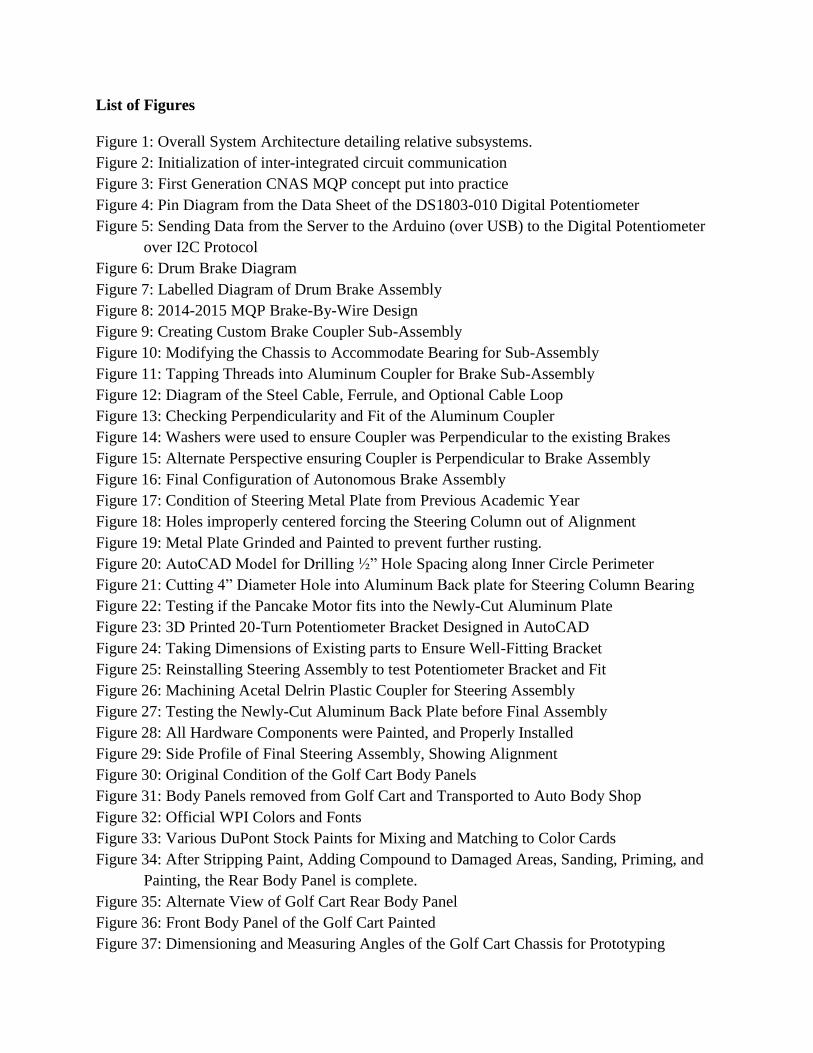
Robocart is an Autonomous Ground Vehicle that requires many subsystems to be
working simultaneously to reach safe and reliable autonomy. Our group broke down the
subsections as follows: Throttle, Brake-by-wire, Steer-by-wire, Chassis Reinforcement, Power
Systems, Server, and Stereoscopic Vision.
Figure 1: Overall System Architecture detailing relative subsystems.
3.2 Design Rationale
3.2.1 Throttle
The Throttle Control on the Autonomous Ground Vehicle had to have high resolution to
have sensitive speed control with the ability to quickly accelerate and decelerate. There must also

12
be safety functionality implemented to ensure the throttle system is robust and reliable in software
applications as well.
To reach these design specifications, our group collectively determined the simplest
implementation would be to replicate the existing accelerator pedal, which is essentially a large
potentiometer ranging from 0 ohms to 5500 ohms.
To replicate this electrical component, we implemented an Addressable Dual Digital
Potentiometer from Maxim, specifically the DS1803-010. Individually, these integrated circuit
chips sell for ~ $2.00 – $3.00 in bulk, and only slightly more for a one-off prototype. These cheap
components allow us to keep the overall cost down and the modularity of a 16-Pin IC chip allows
us to easily swap out the components in case of failure.
This integrated circuit operates, when communicating with a microcontroller over I2C
protocol, by outputting resistances from 0 ohms to 10,000 ohms over 256 steps. This gives us
precise and accurate control over the speed and we have fine control over acceleration and
deceleration through software on the microcontroller as seen in the following chapters.
3.2.2 Brake-by-wire
The existing brake-by-wire system implemented by Prateek Sahay in the 2014 – 2015
academic year utilized a windshield wiper motor. This was a great idea as windshield wiper motors
are powerful and often use worm gears to deliver high torque to the load. These motors could draw
up to 50 amps at stall current, which is within the design specifications of our Sabertooth Dual 60
Amp Motor Driver.
The stall torque is 34 N-m, or 25 ft-lbs. Our group implemented a ¾” coupler to go from
the windshield wiper motor to the industrial bearing bolted onto the I-Beam of the chassis. This
¾” coupler, acting perpendicularly to the motor, acts as a pulley, and using the equation

13
τ = F × r, we should have a force of approximately 66 pounds of force pulling back on the brake
assembly. With a larger diameter coupler, we can maximize distance pulled on the vinyl-coated
wire rope while minimizing the number of rotations allowing the brakes to be deployed more
quickly than designs in previous years.
Considering the mechanical advantage of the brake lever arm from the physical brake
pedal, this should be enough to apply the brakes comparably to a driver depressing the pedal. The
vinyl-coated wire rope, in 3/32” diameter, will support working loads up to 184 pounds, which is
within our force tolerance.
3.2.3 Steer-by-wire
The Steer-by-wire system implemented by Prateek Sahay in the 2014 – 2015 academic
year is a powerful and conceptually sound design, but some further improvements had to be made
for performance and implementation purposes. There was constant issues with aligning the
Steering Column to the existing acrylic plates that were implemented in previous years. Upon
further investigation, as seen in the following chapters, the acrylic plates were not centered and
forcing the steering column out of alignment. Our first design choice was to remove these plates
and come up with an alternate solution.
To correct the perpendicularity of the steering column to the existing steel plate, an
extension had to be made to prevent the potentiometer from hitting the existing aluminum
dashboard. Once the top of the plate was brought out, through small adjustments the plate was now
perpendicular to the natural angle of the steering column. To replace the acrylic plates, and
minimize friction, our team determined an additional ¾” industrial bearing should hold the steering
column in alignment to the plates. Washers were used to fine-tune the distance between the plates
to ensure the chain sits mechanically sound and parallel to all the sprockets.

14
Besides these mechanical adjustments, the motor calculations, torque specifications,
current draw, and speed calculations were all correct from the previous implementations by
Prateek Sahay.
3.2.4 Chassis Reinforcement
A lot of oxidation and rust were seen on the chassis and frame of the Golf Cart that should
be addressed. Our team took wire brushes on power tools and removed the oxidation from the
aluminum, and grinded down whatever exposed rust was on the non-aluminum metals. Oil-based
paint was applied to the non-aluminum metals to prevent further rusting.
Some parts of the I-Beam Chassis running down the golf cart had to be cut to accommodate
the brake systems as seen in the following chapters. These cut segments were reinforced with iron
straight bars bolted to the aluminum assembly. This iron replacement should ensure the structure
remains sturdy for future applications.
The body panels of the Golf Cart were also sanded to remove the existing paint, filled with
compound to remove any dents or imperfections, sanded smooth, painted with primer, and painted
with WPI Maroon as seen in the following chapters. These were cosmetic decisions, but enhanced
the Robocart image we were trying to convey.
3.2.5 Stereoscopic Vision
A graduate student, Guilherme Meira, worked in conjunction with us towards reaching our
goal of a true autonomous platform during the 2015 – 2016 academic year. Guilherme is a Masters
Student who specialized in Raspberry Pi Stereoscopic Vision for his thesis. Based on his
recommendations, our team designed a rack for the front of the golf cart that would allow the
cameras to be spaced at variable distances to maximize the field of view. This gives us design and
testing flexibility further along the process. The modular design of the 80/20 rack would also
15
accommodate additional monitors and hardware to be fitted to the golf cart for prototyping and
testing throughout further development as well. A final prototype could have two brackets that
independently install the cameras in one fixed optimal position. The design features of our
prototype system will become apparent in the following chapters.
3.2.6 Server
In previous academic years other teams working on this Golf Cart attempted to make the
vehicle autonomous via wireless communication to a remote server for image processing.
Although this sounds exceptional in theory, real world latency, bandwidth, and connectivity
jeopardize the safety and performance of the autonomous vehicle. To counter these issues, our
team determined the Golf Cart would have the highest performance with the Server mounted on
the back of the Golf Cart. After software is developed and resources are determined, a smaller and
more cost-effective computer couple be implemented on future prototypes to maximize efficiency.
The steel cage on the Server was modified to a more condensed, but equally protective,
state. This cage was then bolted onto a towing cargo utility rack for vehicles. Modular T-Slotted
80/20 Aluminum bars were bolted onto this cargo rack to accommodate rapid assembly and
disassembly and ensure components can be added and removed, with ease, in the future.
3.2.7 Power Systems
After first inspecting the condition of the Golf Cart during the beginning of the 2015 –
2016 academic year, it was discovered that the existing batteries on the Golf Cart were from 2002
and our team suspected they may not sustain a charge or be usable for untethered operation. After
load testing the fully charged batteries at a local Golf Course facility, the Golf Cart technicians
recommended replacing the batteries. Luckily with our prototype and design flexibility, we were
able to minimize cost and maximize power density for our application. We built a cost and

16
performance matrix in the table on the following page. Our group collectively determined the 29
HM batteries had the highest capacity, charge density, appropriate volume, and justified price for
our application.
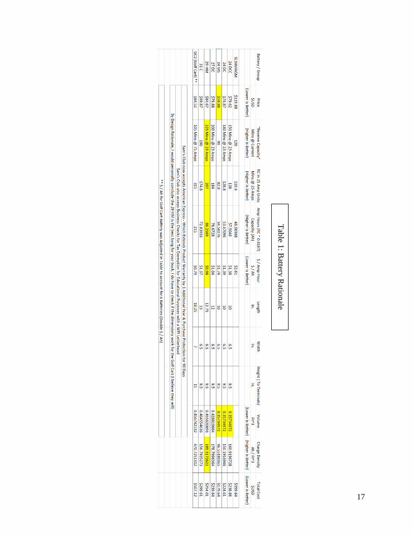
17
Tab
le 1: B
attery R
ationale

18
3.3 Project Logistics
Organization / Management, Coordination, Administration, and Execution
When Raymond and I began this ambitious project, we determined we should do an overall
assessment of the Golf Cart and establish goals for the upcoming academic year. After
disassembling the Golf Cart and getting a better understanding of previous work and current
condition, we broke down our goals based on the following groups:
Power Systems (Rob)
Server and Server Rack (Rob and Ray)
Throttle-by-Wire (Ray)
Brake-by-Wire (Rob)
Steer-by-Wire (Rob)
Stereoscopic Vision (Ray and Guilherme)
Software (Ray and Guilherme)
From a skills perspective, we broke down our talents into the three disciplines of Robotics
Engineering:
Electrical and Computer Engineering – Rob & Ray
Computer Science / Software Engineering - Ray
Mechanical Engineering - Rob
With these subdivisions of labor in the goals list above, each team member is able to focus
their talents where most effective and most relevant. Considering our modular design, and our
common Robotics Engineering background, each of our components will mesh well with the
combined prototype.

19
3.4 Chapter Summary
Our proposed design covers throttle control, braking control, steering control, chassis
reinforcement, and additional reinforcements for mounting stereoscopic vison, server, and power
systems. Each subsystem works independent of each other as its own system, however comes
together to make the entire vehicle functional. By tackling the mechanical, electrical, and software
components, as well as reinforcing the chassis and make improvements to the server and power
systems, we were able to bring the golf cart together as an untethered vehicle capable of
autonomous operation.

20
4 Trinity of Autonomous Vehicles (Throttle, Braking, and Steering)
4.1 Throttle
Throttle control is achieved with an Arduino microcontroller and a DS1803 digital
potentiometer. Since the original golf cart is outfitted with a physical wiper potentiometer
measuring from 5500 ohms at rest and 0 ohms full throttle, we can map the same values to the
digital potentiometer. Through an inter-integrated circuit connection (I2C), communication
between the Arduino and DS1803 can be established. In this specific implementation, we used a
preexisting “Wire” library supplied under a Creative Commons Attribution-ShareAlike 3.0
license. The following code snippet initiates the I2C connection and begins communication with
the Arduino via analog pins A4 and A5 on the Arduino for SCL and SDA pins respectively.

21
The original throttle system operated on a continuously variable potentiometer that
changed its value from 5500 when the acceleration pedal is at rest, to 0 when the pedal is fully
compressed. The simplistic nature of this mechanical system makes it easy to electronically
replicate. There were two replacement control systems the team considered: a linear actuator to
physically compress the acceleration pedal, or manipulate the existing electrical system.
Ultimately the team chose the path of least resistance, making as few physical changes to the golf
cart as necessary.
Figure 2: Initialization of inter-integrated circuit communication
Since the DS1803 uses an 8-bit value (256 decimal values) to control 10,000 ohms of
potentiation, we can obtain control of the resistance within 39 ohm accuracy with each increment
or decrement of the control value. As the golf cart can achieve a maximum velocity of 20 miles
per hour, control of this digital potentiometer would equate to being able to control the velocity of
the golf cart within an accuracy of 0.1418 miles per hour as shown in the equation below:
20 𝑚𝑝ℎ
5500 Ω 𝑥
39 Ω
1 𝑐𝑜𝑛𝑡𝑟𝑜𝑙 𝑡𝑖𝑐𝑘=
0.1418 𝑚𝑝ℎ𝑐𝑜𝑛𝑡𝑟𝑜𝑙 𝑡𝑖𝑐𝑘
⁄

22
To integrate this system with that of the golf cart, the team attached a quad-pull-quad-throw
switch that allows the manual switching between autonomous and manual driving modes design
by the first year MQP team with the CNAS project.
Figure 3: First Generation CNAS MQP concept put into practice
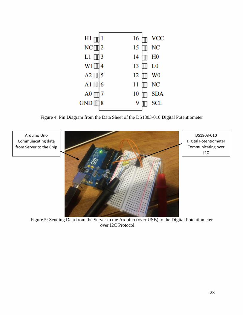
23
Figure 4: Pin Diagram from the Data Sheet of the DS1803-010 Digital Potentiometer
Figure 5: Sending Data from the Server to the Arduino (over USB) to the Digital Potentiometer
over I2C Protocol
DS1803-010
Digital Potentiometer
Communicating over
I2C
Arduino Uno
Communicating data
from Server to the Chip

24
4.2 Braking
The next element our team wanted to address was braking. After the completion and
testing of throttle, our team determined this would be the most appropriate time to implement
and verify the braking system worked. Below is our proposed design flow chart showing the
transition:
The second control system the team tackled was the braking assembly. Shown in Figure 7,
the braking system uses a simple drum mechanism to slow the wheels. As explained below, in
Figure 6, Drum Brakes work with a Brake Cylinder and a Piston. When the Piston is extended, the
two Brake Shoes move outward towards the “Drum” which is on the wheel assembly. The
stationary Brake Shoes expand outward onto the spinning drum, generating friction and slowing
down the wheels. Overtime as the Brake Shoes wear down, the Adjuster Mechanism eases off and
minimizes the gap for the Brake Shoes to come in contact with the Drum. Early on in the project,

25
took off the rear wheels and the hubs, which cover the drum brake assemblies to inspect their
condition. This can be seen below in Figure 8.
The manufacturer of the Golf Cart, Club Car, fitted this Drum Brake design to the golf cart
by implementing a brake wire system which is applied by pressing on the brake pedal, putting
tension on the brake wire, extending the brake shoes which applies friction against the brake drum.
This system is purely mechanical and has no means of autonomous operation. To prepare for
autonomy, the team needed to install a coupler for an electrical system. To accomplish this, the
team designed and created a custom brake coupler attached to a windshield wiper motor with
braided steel wire and outfitted it to the chassis of the golf cart.
Figure 6: Drum Brake Diagram
Figure 7: Labelled Diagram of Drum Brake Assembly
Brake Drum
Brake Lining
Brake Heel
Lugs / Lug Nuts
Brake Shoes Expand out
against the Brake Drum
and apply Friction

26
Figure 8: 2014-2015 MQP Brake-By-Wire Design
The task of creating a custom brake coupler was accomplished by using the lathe in the
Atwater Kent Electrical and Computer Engineering shop. The team bored a hole out of a standard
piece of ¾ inch aluminum stock, which was attached to a solid steel base housing a metal bearing
for smooth rotation. The bored aluminum stock fit securely into the metal bearing assembly and
allowed the mechanical system to be attached to the golf cart.
Figure 9: Creating Custom Brake Coupler Sub-Assembly
Once the construction of the brake assembly was completed, the team needed to install the
assembly onto the chassis of the golf cart. This proved to be far from trivial as parts of the
aluminum I-beam had to be cut away to fit the industrial bearing. To do so, the team used a 4.5”
diameter angle grinder to cut away at the chassis. The team wanted to limit the amount of metal
grinded away from the chassis due to concerns of the tensile strength of the area. To avoid
Lathe in Atwater
Kent ECE Shop
¾” Aluminum Stock
Boring a Hole into the
Aluminum Stock with
a Drill Bit

27
compression and bending of the chassis after the I-beam were cut away, the team reinforced the
chassis with fitted steel plates. The process can be seen in Figures 10 and 11.
Figure 10: Modifying the Chassis to Accommodate Bearing for Sub-Assembly
Figure 11: Tapping Threads into Aluminum Coupler for Brake Sub-Assembly
A hole was drilled out of the Aluminum Coupler, of 3/8” diameter, which was the thickness
of our vinyl-coated steel braided cable. To install the cable, the vinyl-tubing insulation is stripped
from the wire, an aluminum ferrule is attached to incoming and outgoing end of the brake lines
(through the loop of the coupler), and then a swaging tool finalizes the crimp. These elements can
be seen below in the following figures:
Cutting Aluminum
I-Beam on Chassis to
make room for
Industrial Bearing
(Brake Assembly)
4.5” Angle Grinder
Cutting Tool
Location of the
Windshield Wiper
Motor
Location of
Aluminum Coupler
Tapping Threads
into Aluminum
Coupler for Set-
Screw
Using a Vice to
Ensure Coupler
doesn’t Move while
Tapping Threads
Aluminum Ferrule that
will be crimped onto the
Steel-Braided Cable
Optional Cable Loop
(Application Dependent)

28
Figure 12: Diagram of the Steel Cable, Ferrule, and Optional Cable Loop
This would allow a snug and responsive fit when the motor spun the coupler. The larger
diameter of the coupler, ¾”, also maximizes linear travel, applying the brakes more quickly.
Considering the safety aspect of our motivation chapter, this component was crucially important
to the team. Above in Figure 12, you can see a set screw was originally tapped into the first iteration
design of the brake system. Below, in Figure 13, you can see the Set Screw in place and the hole
for the steel braided cable.
Figure 13: Checking Perpendicularity and Fit of the Aluminum Coupler
Aluminum Coupler
with Set-Screw in
place. Checking
Perpendicularity
Hole Drilled out for
Steel Braided Cable
to pull on Existing
Brake System.

29
Figure 14: Washers were used to ensure Coupler was Perpendicular to the existing Brakes
Washers were used to compensate for the angle of the I-Beam chassis that runs through the
frame of the Golf Cart. For best performance, the Motor-Coupler-Bearing system needed to be
perpendicular to the Golf Cart frame and the existing Brake System to maximize torque and
minimize response time. We were able to achieve this with a digital compass and slowly dialing
in 0.0 degrees in respect with the existing brake system.
Figure 15: Alternate Perspective ensuring Coupler is Perpendicular to Brake Assembly
In our final design, we discovered that when the coupler shifted, even subtly, during testing,
that the set screw would become dislodged from the flat portion on our Windshield Wiper Motor.
To correctly fix this, we drilled a hole through the Aluminum coupler, and through the axle of the
Multiple Washers
were used for easy
Calibration and a
Perpendicular Fit.
Holes drilled into
Aluminum I-Beam
Chassis for Windshield
Wiper Motor

30
Windshield Wiper Motor. We then fitted an M3 Bolt through the newly-drilled hole with an M3
Nylock Washer to ensure that the brake assembly wouldn’t come apart, even after repeated use.
Now there should be no slipping when the motor is actuated or when the manual brakes are
depressed repeatedly.
Figure 16: Final Configuration of Autonomous Brake Assembly
The final configuration of the autonomous brake assembly consists of the motor, steel
braided cable, aluminum coupler and bearing assembly shown in Figure 16. Once the entire system
was secured onto the chassis, testing was completed by supplying 12V to the motor until it spun
enough to tension the braided cable and apply tension to the brake line and applied the brakes.
Once this proved to work successfully, the configuration was attached to a Dimension Engineering
Sabertooth 2x60 motor controller which supplied power to both the steering and braking motors.
The motor controller operates via microcontroller pulses such as a PWM signal with a 2
millisecond period to control both speed and direction of the motors attach to the “motor 1” and
“motor 2” lines corresponding to signals 1 and 2 respectively.
Windshield Wiper
Motor Installed
Steel Braided Cable
Tensioned and
Installed on Brake
Side.
Steel Braided Cable
looped through and
crimped
Chassis Reinforced
using 1½” Iron Bar
and bolts.
Set Screw Replaced
with bolt for higher
torque

31
4.3 Steering
Like the other control systems of the golf cart, steering configuration was complete in 3
parts. First we assessed the current state of the assembly to locate areas of improvement, then the
design and implementation of complete system, and finally verifying the new installation. As
shown in Figure 17, the original steering configuration was out of alignment. This results in
difficulty moving the chain and sprocket when applying control to the steering motor.
Figure 17: Condition of Steering Metal Plate from Previous Academic Year
Original Plate from
Previous Group
showing age

32
Figure 18: Holes improperly centered forcing the Steering Column out of Alignment
To address this issue, the team designed and cut an aluminum back plate to retrofit the
previous design. This new design is sturdy enough to withstand the weight of the steering motor
without bending, which would allow the steering column to rest perpendicular to the steering
column.
Figure 19: Metal Plate Grinded and Painted to prevent further rusting.
The cutting of our aluminum back plate design proved to be an obstacle as we did not have
access to a 4” diameter hole saw, nor a computer numerical control (CNC) machine. To make the
proper cut, the team drilled around the circumference of the desired hole and sanded away excess
using a Dremel. The fit of the motor is shown in Figure 22.
Holes Laser-Cut
from Previous
Group Clearly out
of Alignment
Fresh Coat of Oil-
Based Paint (to
prevent future
rusting) Applied to
Old Plate

33
Figure 20: AutoCAD Model for Drilling ½” Hole Spacing along Inner Circle Perimeter
Figure 21: Cutting 4” Diameter Hole into Aluminum Back plate for Steering Column Bearing
Figure 22: Testing if the Pancake Motor fits into the Newly-Cut Aluminum Plate
The next stage of the redesign was to mount the original housing for the steering control
potentiometer on the new design. In doing so, the team realized that when the motor spun at high
Cutting Supplemental
Aluminum Plate to
Support Steering
Column Bearing
Creatively cutting
out a 4” Diameter
Hole in the
aluminum without
a Hole Saw
Pancake Motor has
Snug Fit on newly-
cut Aluminum Plate
AutoCAD Template
for drilling holes
along the perimeter
of an inner circle

34
enough speeds, the potentiometer would freely spin in its housing. This would be a problem when
trying to obtain accurate information about the position of the steering wheel. The team addressed
this issue with a 20-turn potentiometer bracket that secured the potentiometer in place while the
motor is spinning. The design and implementation of the bracket is shown in Figures 23, 24 and
25.
Figure 23: 3D Printed 20-Turn Potentiometer Bracket Designed in AutoCAD
Figure 24: Taking Dimensions of Existing parts to Ensure Well-Fitting Bracket
3D Printed
Potentiometer
Bracket with Notch
to prevent spinning
Measuring all
components
precisely with
Digital Caliber
Measuring Tool
20-Turn
Potentiometer for
Steering Position
Measurements

35
Figure 25: Reinstalling Steering Assembly to test Potentiometer Bracket and Fit
The final step in completing the steering assembly was to ensure the alignment of the
sprocket-steering column system was perpendicular. This was completed with an Acetal Delrin
plastic coupler machined on a lathe that ensured the steering column remained stable in the new
design. Such a piece would secure the steering column in place as well as absorb any shock causing
the steering column to quiver in place.
Figure 26: Machining Acetal Delrin Plastic Coupler for Steering Assembly
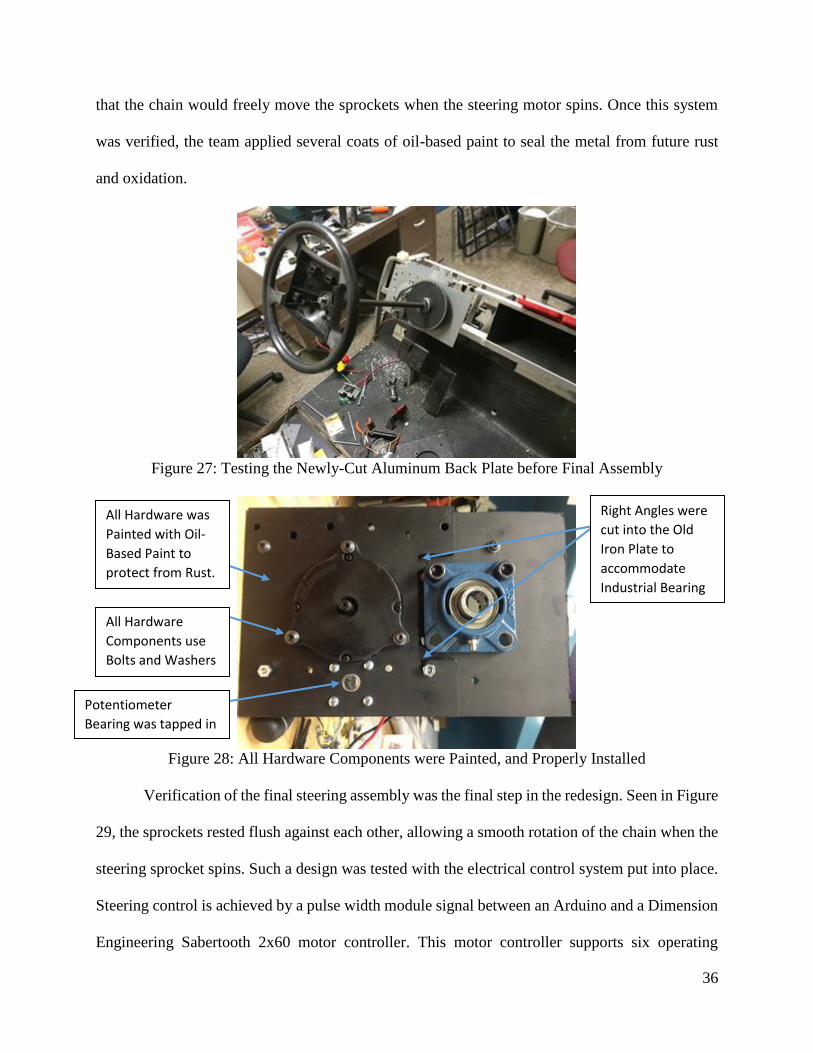
Once the alignment of the steering configuration was secured, the team tested the fit of the
new design on the golf cart. Measurements were taking to ensure that each sprocket was flush so
White 3D Printed
Bracket installed on
the Potentiometer
Lathe in Atwater
Kent ECE Shop
Acetal Delrin Plastic
Drilling out ¾” Hole
for the Steering
Column to fit
through Coupler
36
that the chain would freely move the sprockets when the steering motor spins. Once this system
was verified, the team applied several coats of oil-based paint to seal the metal from future rust
and oxidation.
Figure 27: Testing the Newly-Cut Aluminum Back Plate before Final Assembly
Figure 28: All Hardware Components were Painted, and Properly Installed
Verification of the final steering assembly was the final step in the redesign. Seen in Figure
29, the sprockets rested flush against each other, allowing a smooth rotation of the chain when the
steering sprocket spins. Such a design was tested with the electrical control system put into place.
Steering control is achieved by a pulse width module signal between an Arduino and a Dimension
Engineering Sabertooth 2x60 motor controller. This motor controller supports six operating
Right Angles were
cut into the Old
Iron Plate to
accommodate
Industrial Bearing
All Hardware was
Painted with Oil-
Based Paint to
protect from Rust.
All Hardware
Components use
Bolts and Washers
Potentiometer
Bearing was tapped in

37
modes, of which we used the Mode 2 which allows control via microcontroller pulses. The control
signal uses a PWM signal with a 2ms period to control both speed and direction. With the Arduino
Servo Library, we can effectively control the speed and direction of each motor attached to the
Sabertooth motor controller.
Figure 29: Side Profile of Final Steering Assembly, Showing Alignment
4.4 Chapter Summary
The implementation of the three main subsystems was the focus of this project. Each
subsystem can operate completely separated from the rest of Robocart, which adheres to one of
the project’s overall goal of modularity. After each system was design and built, several tests were
conducted on each proof of concept before implementing on the actual chassis. Once the subsystem
was installed onto the golf cart, verification of functionality was once again conducted by using
the server to communicate to each subsystem connected to an Arduino micro controller.
Sprockets in
Perfect Parallel
Alignment

38
5 Additional Enhancements for the Autonomous Prototype
5.1 Body Restoration
When our team first started the project, we wanted to revitalize the Robocart name and
image. The following chapter describes the restoration process the team undertook to give
Robocart eye-catching appeal. Since the body of the golf cart should not be physically modified
for it to still fit the chassis, we focused on proper automotive painting procedure and a clean finish.
We wanted to give the golf cart a new polished look to represent the modern technology
that it is showcasing. At the beginning, our golf cart had hand-brushed lackluster red paint on it
with dings and chips. After taking apart the golf cart to assess the condition of the chassis, the body
panels were brought to County Line Auto Body in Jackson, New Jersey. The original paint job can
be seen in the following Figures 30 and 31:
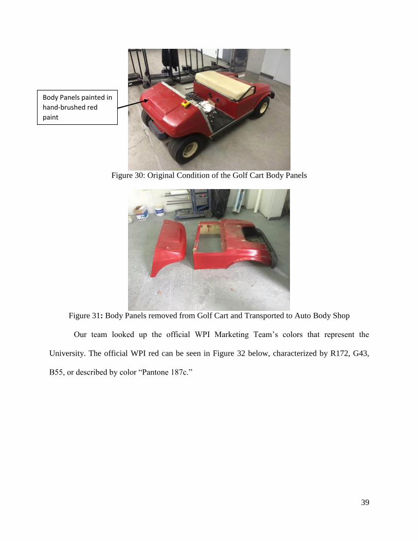
39
Figure 30: Original Condition of the Golf Cart Body Panels
Figure 31: Body Panels removed from Golf Cart and Transported to Auto Body Shop
Our team looked up the official WPI Marketing Team’s colors that represent the
University. The official WPI red can be seen in Figure 32 below, characterized by R172, G43,
B55, or described by color “Pantone 187c.”
Body Panels painted in
hand-brushed red
paint

40
Figure 32: Official WPI Colors and Fonts
With access to an Auto Body DuPont paint shop, our team was able to mix the perfect
blend of colors to match the university’s trademark hue. All of the paint canisters can be seen
below, in Figure 33, each with a significant color code identifier:
Figure 33: Various DuPont Stock Paints for Mixing and Matching to Color Cards
After sandblasting off the old paint job, filling in significant gouges, scratches, and
imperfections, sanding the body smooth, we painted the body with a primer base coat. Then we
Color that would be
painted on the Golf
Cart Body Panels

41
took the WPI blend of red with gloss and pearls added and painted the body. A clear coat was
added over the exterior to protect the finish. This is the new image of Robocart:
Figure 34: After Stripping Paint, Adding Compound to Damaged Areas, Sanding, Priming, and
Painting, the Rear Body Panel is complete.
Figure 35 and 36: Alternate View of Rear Body Panel (left) Front Body Panel (right)
Thin Metal Wire was
used to suspend the
body panel during
drying

42
5.2 Front Rack and Raspberry Pi / Camera Mounts
As mentioned in our proposed design, our team determined we needed some sort of
modular rack in the front of the golf cart to accommodate the Raspberry Pi Computers, Camera
Modules, power lines, Ethernet cables, monitors, and other prototyping equipment. Part of our
design rationale was to have this assembly be modular, so we could easily remove it, service it,
disassemble, and reassemble it at any given time. When prototyping anything, you need accurate
dimensions, which can be seen below when taken with a digital level from an iPhone
accelerometer.

43
Figure 37: Dimensioning and Measuring Angles of the Golf Cart Chassis for Prototyping
Our team 3-D Printed a polylactic acid block which we secured to the aluminum dashboard
of the Golf Cart chassis with bolts and hex nuts. Using “Hex Nut Traps” which are the rectangular
holes on the side of the prototyped part, a 1/4-20 hex nut will sit perfectly flush along its shorter
edges, preventing rotation. A hole is exposed on the underside of the plastic part. A complementary
hole is drilled through the Golf Cart Aluminum Dashboard, and a bolt is secured through the plastic
to the metal hex nut. This ensures a strong, tight fit without using many materials. This design
retains simplicity, minimizes number of parts, and ensures strength while maintaining the overall
modularity we had in mind. Multiple pictures of this design can be seen in the following figures:
Figure 38: Testing fit of 3D Printed Bracket and the strength of the 80/20 Mounted on the block
Measuring the Angle /
Incline of the
Dashboard
Estimating 3D Printed
Block Dimensions to
make Front Rack
Parallel to Floor Pans
Describing Chassis
Features that need to
be accommodated for
in CAD
80/20 T-Slot Extruded
Aluminum bolted to
3D Printed Assembly
3D Printed Block
orients the Aluminum
to be Parallel to the
Floor

44
Figure 39: Side Perspective of Front Rack to ensure Perpendicularity to Floor Pans
To mount the Raspberry Pi Computers to the 80/20 T-Slotted Aluminum Extrusion, our
team designed and 3D-Printed a bracket out of polylactic acid that would match the mounting
holes of the Raspberry Pi and center 1/4-20 bolts to be mounted onto the 80/20 framing solution.
Triangles were cut out of the design as it was not a structural load-bearing component to save on
plastic, and cost, without compromising the integrity of the design. The narrower rectangle, in
Figure 40, is intended to be below the Ethernet and USB ports to match the footprint of the
Raspberry Pi.
Figure 40: 3D-Printed Raspberry Pi to 80/20 Bracket we designed.
Raspberry Pi is
mounted by M3 Bolts
on these 4 corner
holes
1/4-20 Bolts are used
on the sides to attach
to the 80/20 Front
Rack
Triangles were cut out
to maintain strong
and ridged design
while minimizing cost

45
Figure 41: Checking Raspberry Pi Hole Alignment on the 3D Printed Bracket
Figure 42: Checking compressional strength of 3D Printed Bracket and Ease of Adjustability
Figure 43: Rendering of Raspberry Pi Camera Bracket our team designed.
T-Nuts were used to
slide along the 80/20
for fine adjustments
but once tightened,
remain locked in the
channel of the
aluminum
Raspberry Pi Camera
Mounting Holes
M3 Bolt Risers for the
Raspberry Pi Camera
Plate

46
Figure 44: Raspberry Pi Camera Bolted to Bracket and Aligns with Raspberry Pi Hole Mounts
Figure 45: Checking Fit of Raspberry Pi – 80/20 – Camera Bracket System
M3 Bolts securing the
Camera Bracket to the
Raspberry Pi
White 3D Printed
Camera to Raspberry
Pi Bracket
1/4-20 Bolts Secure
the Raspberry Pi –
Camera system to the
Modular 80/20
GPIO Pins are still
exposed for additional
components to be
connected to
Raspberry Pi

47
Figure 46: Screens attached to the modular 80/20 rack for testing and displaying functionality
Figure 47: Alternate Perspective of First Iteration Prototype of Autonomous Ground Vehicle
Modular 80/20 allows
for additional
components, such as
monitors, to be
mounted to the Front
Rack
Raw Camera Data,
Server Information,
Terminal Console, and
other Valuable
Information can be
seen on the Prototype
Displays
The Raspberry Pi with
Cameras can translate
along the front of the
rail to optimize Field
of View during testing.

48
5.3 Server (Software) and Server Rack (Hardware)
In previous years, other MQP teams attempted to wirelessly transmit raw data to a remote
server for image processing and computation. Although this worked as a proof of concept,
problems with latency, occlusion, and packet loss were providing erroneous data to the Golf Cart.
To rectify this, our team determined it would be optimal to move the Server onto the cart and tether
all of the image capturing devices (Raspberry Pi) to the Server over Ethernet cables through a local
unmanaged network switch. This would provide low-latency, high bandwidth, high resolution and
optimal performance for navigating off of processed images. A previous MQP team built a metal
cage around the server to protect it when deployed in the field for testing.

49
Figure 48: Original Angle-Iron Enclosure to protect the Server
To move the server onto the Golf Cart, our team looked at other commercially viable
solutions for cargo and equipment. We found utility trays (See Figure 49) and cargo racks (see
Figure 50) but these were usually priced outside of our budget and provided us with limited
attachment options. Our team opted for a custom modular design using a cost-effective commonly
available tow-hitch utility rack and 80/20 T-Slotted Aluminum Extrusion.
Figure 49: Cargo Box / Tray Solution from JustGolfCarts.com
Upon starting project,
Server was enclosed in
this steel frame and
was meant to be
stored off the Golf
Cart.
50
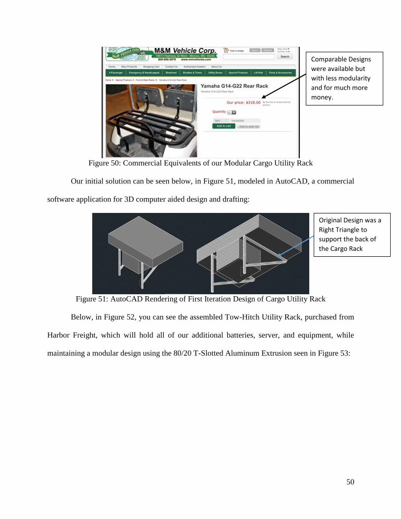
Figure 50: Commercial Equivalents of our Modular Cargo Utility Rack
Our initial solution can be seen below, in Figure 51, modeled in AutoCAD, a commercial
software application for 3D computer aided design and drafting:
Figure 51: AutoCAD Rendering of First Iteration Design of Cargo Utility Rack
Below, in Figure 52, you can see the assembled Tow-Hitch Utility Rack, purchased from
Harbor Freight, which will hold all of our additional batteries, server, and equipment, while
maintaining a modular design using the 80/20 T-Slotted Aluminum Extrusion seen in Figure 53:
Original Design was a
Right Triangle to
support the back of
the Cargo Rack
Comparable Designs
were available but
with less modularity
and for much more
money.
51
Figure 52: Square Tubular Based Construction on Towing Cargo Rack
Figure 53: Taking Inventory of Various Lengths of 80/20 Modular Framing Solution
Air Incorporated generously donated scrap pieces of 80/20 to use for our Project. Our team
took inventory of the lengths, features, and imperfections on the aluminum extrusion before
allocating them towards our project. These allocations and inventory sheets can be seen below in
Table 2:
Cargo Rack has similar
metal square tubular
construction as seen
in previously stated
commercial products.
This is a $40 Cargo
Tow Rack from Harbor
Freight which will
adequately cover our
purposes for this
prototype.

52
Table 2: 80/20 T-Slotted Aluminum Scrap Inventory Sheet
After speaking with the mechanical engineers there and drawing out our design on
Isometric Drafting Paper, we had a pretty good understanding of what type of design
considerations we should keep in mind. Our drafts can be seen below in Figure 54:
Figure 54: Design was drawn out on Isometric Drafting Paper.
Our team considered commercially manufactured 80/20 90o Pivot Brackets, as seen below
in Figure 55. They are very strong and excellent in specific applications, but were overblown for
our application. Our team determined it was more cost effective and convenient to 3D-Print Pivot
Brackets as the polymer Polylactic Acid (PLA) was beyond strong enough for our application.
Original Location of
90-Degree Aluminum
Brackets for Structural
Integrity
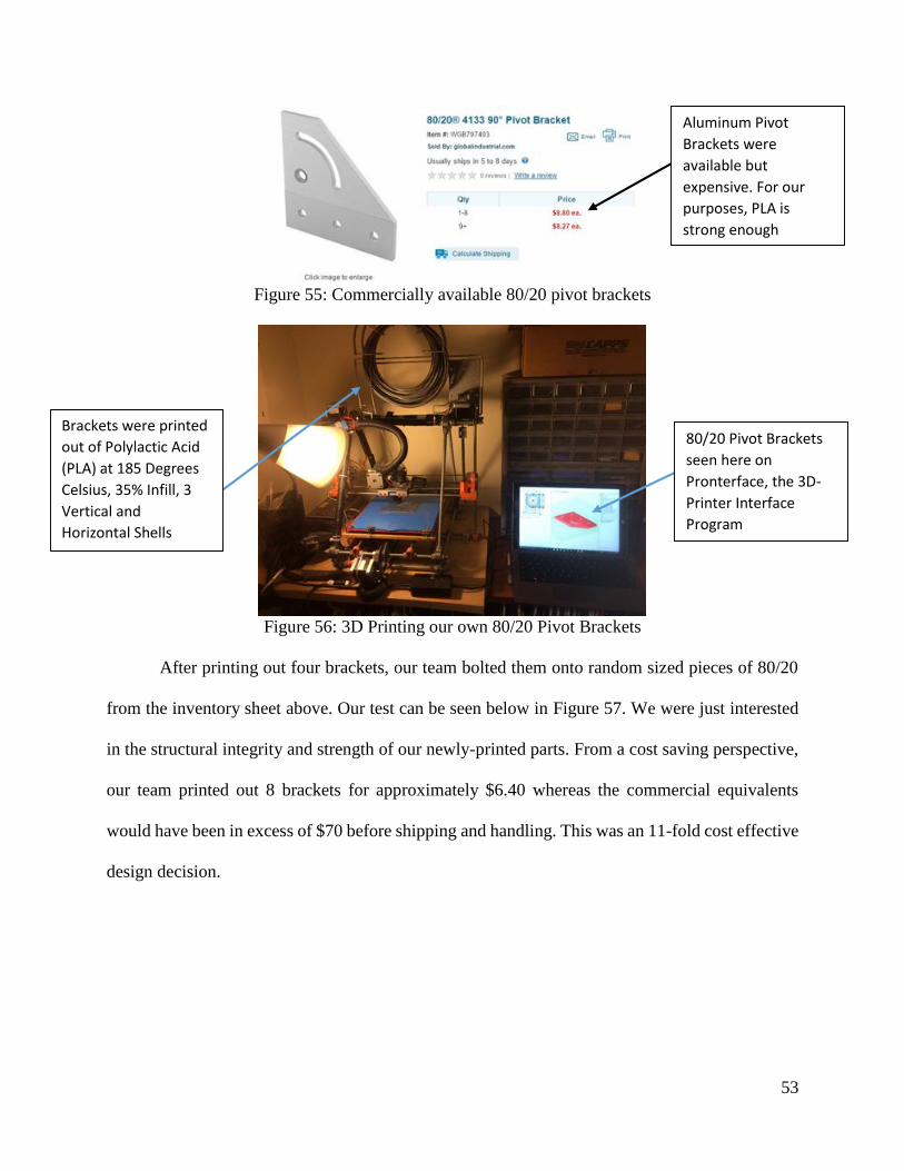
53
Figure 55: Commercially available 80/20 pivot brackets
Figure 56: 3D Printing our own 80/20 Pivot Brackets
After printing out four brackets, our team bolted them onto random sized pieces of 80/20
from the inventory sheet above. Our test can be seen below in Figure 57. We were just interested
in the structural integrity and strength of our newly-printed parts. From a cost saving perspective,
our team printed out 8 brackets for approximately $6.40 whereas the commercial equivalents
would have been in excess of $70 before shipping and handling. This was an 11-fold cost effective
design decision.
80/20 Pivot Brackets
seen here on
Pronterface, the 3D-
Printer Interface
Program
Brackets were printed
out of Polylactic Acid
(PLA) at 185 Degrees
Celsius, 35% Infill, 3
Vertical and
Horizontal Shells
Aluminum Pivot
Brackets were
available but
expensive. For our
purposes, PLA is
strong enough

54
Figure 57: Testing the strength and fit of our 3D-Printed 80/20 Pivot Brackets
To reassure our peers of the strength of Polylactic Acid (PLA), Makerbot Industries, a
New York City-based company founded to engineer and produce 3D-Printers, conducted a study
on the impact, tensile, compressive, and flexural strengths of 3D-Printed plastics. Their results
can be seen below in Figure 58.
Figure 58: Makerbot’s PLA and ABS Strength Data for 3D-Printed Plastics
Three Aluminum
Angle Brackets were
used here to ensure
structural integrity
Two Pivot Brackets
were added with a
Diagonal Member to
support the load
acting on the end of
the 80/20 Bar

55
With these numbers in mind and our application considered, we carefully designed our
Pivot Brackets with flexural and compressive strength in mind to ensure structural integrity. The
annotations and labels in Figure 59 explain our design choices for our brackets:
Figure 59: Showing the Finish and Construction of our 3D-Printed 80/20 Pivot Brackets
5.3.1 Attaching the Cargo Utility Rack Posts to the Prototype:
Using the geometry of the existing holes on the Golf Cart, such as the ones for the old
backrests or the canopy top, our team was able to frame out the parallel and perpendicular lines on
the rear golf cart panel. These markings allowed us to cut lines perpendicular to each other and
prevent paint chipping. Both of these elements are required to get a snug, professional, and
polished look for the final prototype:
Figure 60: Preparing the Rear Body Panel for Modification by Drilling Pilot Holes in the Corners
Concentric Layers on
the Mounting Holes
for Compressive
Strength on Bolts
Rectilinear Layers on
the Surface for
Flexural Strength
Pilot holes drilled into
the corners before
linear cuts are made
Many layers of
painters tape was
used to prevent Paint
Chipping

56
After pilot holes were drilled in the corners, a sharp cutting blade was used on a Dremel,
at medium speeds, to cut through the panel. When looking down, the holes should resemble a 1.25”
x 1.25” square. Due to the stylish and sloping nature of the back of the Golf Cart to accommodate
golf club bags, precise measuring tools had to be used to ensure proper cuts were made. Our
painters tape framing and notes can be seen below in Figure 61:
Figure 61: Framing and Layering Painters Tape on the Body Panel to Prepare for Cutting
Additional layers of Painter’s Tape was added along the perimeter of the cuts to ensure that
the paint didn’t chip up while cleaning up the cuts. Once the initial cuts were made, the cutting
blade was swapped out for a sanding drum on the Dremel. At slow to medium speeds, any
remaining excess from the cuts were sanded down to leave a polished clean cut in the body panels.
This process can be seen below in Figure 62:
Using Geometry of the
Existing Holes, Parallel
and Perpendicular
Painters Tape was laid
on the Body Panels
Using a Dremel and
cutting attachment,
straight lines were cut
through the body
panel before sanding

57
Figure 62: Adding Additional Layers of Painters Tape and Sanding down any rough cuts
After dimensioning all of the edges and testing the fit with the 1¼” square tubing, the
painters tape was removed. The square tubing was secured once again to the chassis using the ½”
bolts and hex nuts and the body was lowered over the posts and snug against the chassis. Due to
careful measurement and planning, the resulting product came out very clean as seen below in
Figure 63:
Figure 63: Square Tubing fitting flush with the new cuts in the rear Body Panel
Additional layers of
Painters Tape was
applied to ensure no
further paint chipping
Sanding Attachment
was used on Cordless
Dremel to smooth out
rough edges for
precise and snug fit
The 1-1/4” Square
Tubing fits snug and
flush with the new
cuts in the Body.
58
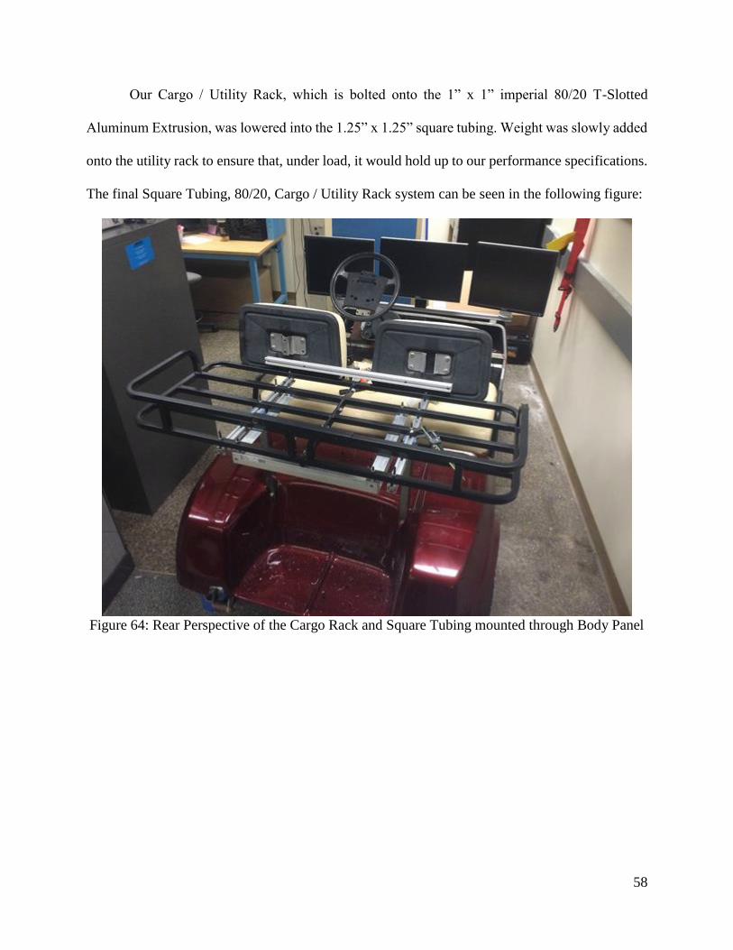
Our Cargo / Utility Rack, which is bolted onto the 1” x 1” imperial 80/20 T-Slotted
Aluminum Extrusion, was lowered into the 1.25” x 1.25” square tubing. Weight was slowly added
onto the utility rack to ensure that, under load, it would hold up to our performance specifications.
The final Square Tubing, 80/20, Cargo / Utility Rack system can be seen in the following figure:
Figure 64: Rear Perspective of the Cargo Rack and Square Tubing mounted through Body Panel
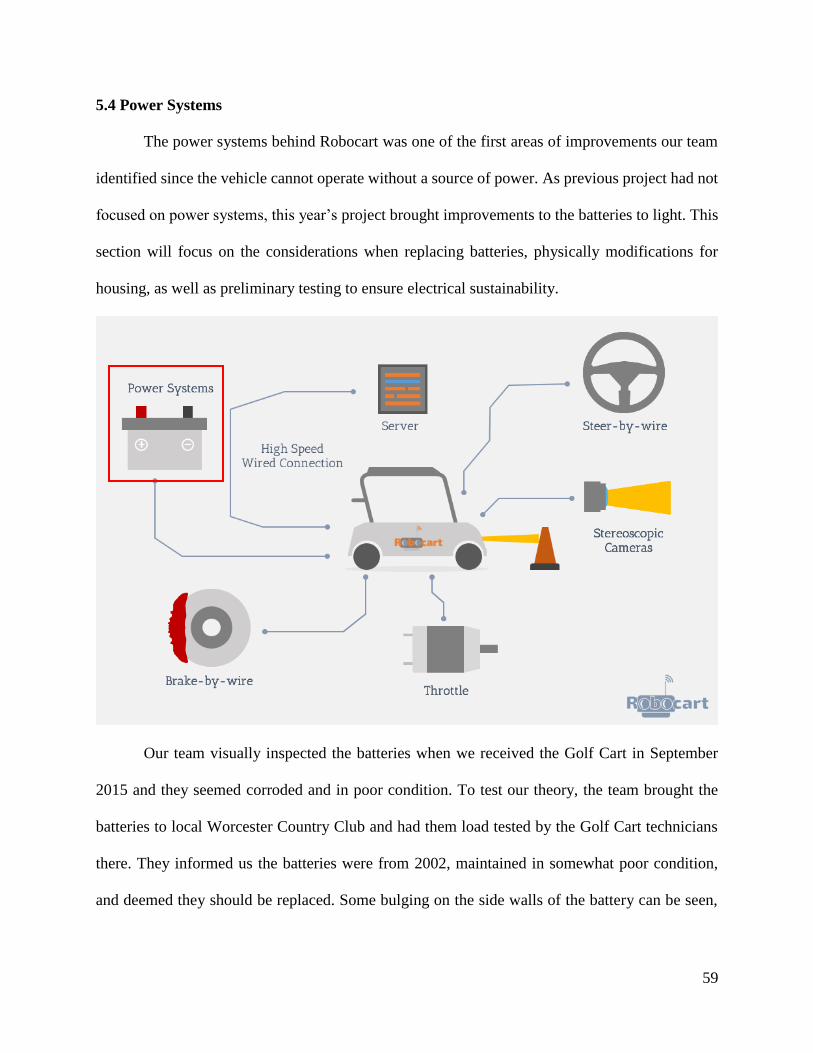
59
5.4 Power Systems
The power systems behind Robocart was one of the first areas of improvements our team
identified since the vehicle cannot operate without a source of power. As previous project had not
focused on power systems, this year’s project brought improvements to the batteries to light. This
section will focus on the considerations when replacing batteries, physically modifications for
housing, as well as preliminary testing to ensure electrical sustainability.
Our team visually inspected the batteries when we received the Golf Cart in September
2015 and they seemed corroded and in poor condition. To test our theory, the team brought the
batteries to local Worcester Country Club and had them load tested by the Golf Cart technicians
there. They informed us the batteries were from 2002, maintained in somewhat poor condition,
and deemed they should be replaced. Some bulging on the side walls of the battery can be seen,

60
which is usually a sign of a weathered battery and should be replaced, when possible. The original
condition of the batteries can be seen below in Figure 65 and Figure 66:
Figure 65: Condition of the Golf Cart Batteries starting the project in September 2015
Figure 66: Batteries exhibiting bulging on the sides and corrosion at the terminals.
Battery Details:
Configuration: 6x 2002 8-Volt NAPA Deep Cycle Batteries
Condition: Charged, Load Tested, Needed to be replaced
Proposed Solution: Replace with Marine Grade Deep Cycle Batteries for Cost Effectiveness
Batteries Considered: -AGM (Absorbed Glass Mat) -Wet Cell (Flooded) -Gel Cell
Batteries were 8V
NAPA Specialty Golf
Cart Batteries from
2002
Lots of corrosion can
be seen around the
terminals The batteries were
also bulging on the
sides

61
Our team went out to local battery department stores and looked at the different form
factors, prices and capacities. Afterwards we determined price per amp hour, volume, charge
density, and total cost of the entire bank. Our results can be seen below in Table 3:
Table 3: Battery Design Rationale
Figure 67: Battery Trays showing signs of rust from weathering and battery acid exposure.
Our team determined it would be most structurally sound if we installed a panel that was
braced on both sides, at all points, for the best case scenario results. Our team opted for ¼” Medium
Density Fiberboard (MDF) due to its high manufacturer standards for straightness of the panels.
We then drilled four holes through each board, and through the aluminum. We secured the boards
to the chassis with bolts, washers, and hex nuts. We placed two batteries cautiously on the center
Existing Battery Trays
were showing rusting
and covered with
some battery acid.

62
battery tray, and to our expectation, the panels supported the batteries without any sign of wear,
warping, or deviation. We deemed this upgrade a success.
Figure 68: New Battery Pans bolted to the Golf Cart Aluminum Chassis
5.5 Chapter Summary
A secondary goal of this year’s project was to improve the physical appearance of
Robocart, as well as reinforce the existing chassis with mechanical improvements. Once body
restoration had been complete, the team worked on designing mechanical components to house
the Server and raspberry pi cameras for future project work. Finally to finish chassis renewal, the
team analyzed and replaced the existing power systems with a new battery configuration.
Wood Floor Pans were
Cut, Painted, and
bolted to sturdy parts
of the existing chassis
to support the weight
of the new batteries
and protect the
electronics
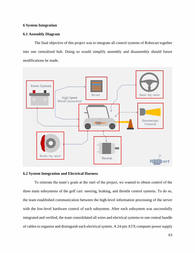
63
6 System Integration
6.1 Assembly Diagram
The final objective of this project was to integrate all control systems of Robocart together
into one centralized hub. Doing so would simplify assembly and disassembly should future
modifications be made.
6.2 System Integration and Electrical Harness
To reiterate the team’s goals at the start of the project, we wanted to obtain control of the
three main subsystems of the golf cart: steering, braking, and throttle control systems. To do so,
the team established communication between the high-level information processing of the server
with the low-level hardware control of each subsystem. After each subsystem was successfully
integrated and verified, the team consolidated all wires and electrical systems to one central bundle
of cables to organize and distinguish each electrical system. A 24-pin ATX computer power supply
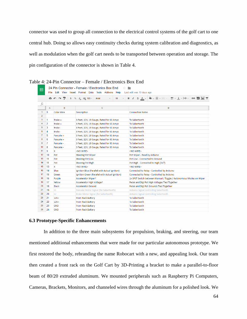
64
connector was used to group all connection to the electrical control systems of the golf cart to one
central hub. Doing so allows easy continuity checks during system calibration and diagnostics, as
well as modulation when the golf cart needs to be transported between operation and storage. The
pin configuration of the connector is shown in Table 4.
Table 4: 24-Pin Connector – Female / Electronics Box End
6.3 Prototype-Specific Enhancements
In addition to the three main subsystems for propulsion, braking, and steering, our team
mentioned additional enhancements that were made for our particular autonomous prototype. We
first restored the body, rebranding the name Robocart with a new, and appealing look. Our team
then created a front rack on the Golf Cart by 3D-Printing a bracket to make a parallel-to-floor
beam of 80/20 extruded aluminum. We mounted peripherals such as Raspberry Pi Computers,
Cameras, Brackets, Monitors, and channeled wires through the aluminum for a polished look. We

65
then tackled the Server integration with both hardware and software. From a physical, hardware,
perspective, our team cut the cage that housed the server into a small form factor and then bolted
it onto a cargo towing utility rack. We framed the rest of the utility rack with modular 80/20 and
installed square tubing on the chassis of the golf cart to accommodate our custom rack. We then
added additional power supplies to the cargo rack to increase the mobile longevity of the power
systems on board the golf cart. For software, the server was reimaged with Ubuntu 14.04. All
embedded microcontrollers, Arduinos, were hooked up to the server through USB. All the
Raspberry Pi Computers communicated with the server over an Ethernet Switch, mounted to the
Golf Cart. Guilherme Meira handled image processing with the Raspberry Pi Cameras and mapped
control commands to the Arduino Serial Monitor which drove our mechanical subsystems. Lastly
our team tackled the power systems. We replaced the older poor-conditioned deep cycle batteries
for a brand new set of marine-grade deep cycle batteries. With flexibility in form factor, we were
able to use a cost matrix to get the best performance per dollar and keep the costs down. After
some verification testing and proof of concept testing, we pushed our design to the extremes and
ensured it would hold up to the test conditions for next year’s software applications. With these
three essential systems followed by the four enhancement systems, we were able to accomplish all
seven goals addressed in our proposed approach top-level diagram above.
6.4 Chapter Summary
The integration of the system focused on bring all electrical components added to Robocart
to one centralized hub. Using the server as a command center, we were able to communicate to
each subsystem of the golf cart and remotely control each of the subsystems. Once control was
verified, all wires and electrical components were consolidated for each access and removal should
the golf cart need to be relocated.

66
7 Experimental Tests
7.1 Introduction
Throughout the course of this project, the team compiled a list of experimental tests and
procedures to which had both positive and negative outcomes. In this chapter, we will focus on
these procedures and their outcomes. Let this chapter be a stepping stone for which future project
teams can use as a guide for potential risks and failures.
7.2 Steering Over-rotation
Due to the design of the current rack and pinion system of the steering assembly, it is
possible to spin the steering wheel and attempt to turn the wheel beyond its physical limitations.
Doing so would cause the rack and pinion to separate, making it impossible to turn the wheel
unless the system was reassembled. Such a case could also cause the rack and pinion or subparts
to bend or shatter. Neither scenarios would have a quick fix, therefore it is in the project’s best
benefit to refrain from overdriving the steering without using feedback from the steering
potentiometer.
7.3 Steering Overdrive
Another potential threat to the stability of the steering system is the overdrive of the
steering motor. Supplying the motor with a voltage beyond 6V would destabilize the chain and
sprocket, causing the chain to separate from the sprockets. To resolve this issue, reattached the
chain around the sprockets in the order from smallest to largest. When parts of the chain is around
the largest sprocket (the steering column sprocket), slowly spin the sprocket until the entire chain
rests fully around all sprockets. It may help if the set screws for each sprocket is loosened such
that each spins freely. Another method that the team found was effective in reattaching the chain
was to take all three sprockets off of the steering assembly, wrap the chain around the largest
67
sprocket, then fit the smaller two within the chain. Afterwards, reassemble the three sprockets back
onto the steering column assembly and tighten the set screws.
7.4 Throttle Signal Short
An important aspect of the operation of the autonomous golf cart lies in throttle control.
As stated in the chapters covering the original operation of the golf cart, the onboard computer
handles every electrical operation of the entire vehicle. However, the system is still simplistic in
nature as this vehicle was manufactured in the year 1995. That being said, the signal the computer
reads as throttle control is an analog signal representing the voltage of the continuously variable
potentiometer that changes when the acceleration pedal is compressed. Should there be a short in
any part of this system, the computer will read the signal as a 0V signal, which is when the
acceleration pedal fully compressed. For the current state of the system, this is dangerous when
implementing autonomous operations.
7.5 Steering Potentiometer
Part of this team’s accomplishments included creating a bracket to mount and secure the
steering potentiometer onto the back-plate of the steering assembly. By doing so, the potentiometer
would no longer be allowed to freely rotate should enough torque be applied from the steering
motor. This year’s design allows accurate readings from the potentiometer. However, there is no
mechanical stop to which stops the spinning of the motor when the potentiometer have reached
either a maximum or minimum. When the potentiometer is spun beyond its limits, this would cause
erroneous readings from the potentiometer as well as affect future readings.
7.6 Speed Control
There are currently no means of monitoring the velocity of the vehicle when in operation.
The current method of speed control is by mapping the digital potentiometer values to estimated
68
velocities as the vehicle is driving on a flat surface. However, these values would change with the
slightest change in inclination. Future considerations may include outfitting a motor encoder to the
electrical motor powering the golf cart or the back wheel shaft to record the rotations per minute.
Because such a system still relies on relative positons and velocities, slippage would still need to
be account for. Combining internal relative data with global positioning satellite data may be a
possible solution for future teams to explore further.
7.7 Braking Motor
Much like any motor, when the motor stalls, it will pull as much current as it can from its
power supply until either the supply or the motor overheats or burns out. The windshield wiper
motor attached to the braking assembly only needs several rotations in either the clockwise or
counterclockwise direction to apply tension to the brake line and engage the brakes. Any attempt
to drive the motor once the brakes are fully engaged will cause the motor to stall. Stalling the motor
for extended periods of time may potentially damage both the motor and the power supply it is
connected to.
7.8 Chapter Summary
The implementation of the three main subsystems this project had focused on did not prove
to be trivial. As the team designed and implemented each subsystem, new problems arose and were
addressed. Main issues around the control of the subsystems involved being aware of the physical
limitations of the existing golf cart as the team had to work around these limitations by making
note in software.

69
8 Conclusion & Future Work
At the conclusion of this year’s project work, the team has outfitted a 1995 Club Car golf
cart with the mechanical and electrical systems in preparation for autonomous operation. The team
improved upon previous project teams’ designs, as well as providing new designs covering flaws
not addressed in previous projects. Although the team tackled all three control systems of the
vehicle: steering, throttle, and brake control, the project is by no means complete. The following
sections outline potential areas of improvement for future teams to build upon, as well as problems
mentioned from the Experimental Tests chapters that may be addressed to improve the quality of
testing and operation.
8.1 Mobile Path Planning and Collision avoidance
Mobile path planning is currently a separate project worked as a Master’s thesis under the
advisory of Dr. Alexander Wyglinski. Areas of improvement include but not limited to serial
communication between low-level control systems and high-level navigation commands, and
further integration between throttle, brakes, and steering control.
Work involving low-level collision avoidance mechanism may also be further explored as
currently there is no mechanism is directly communicate with the control systems of the golf cart
in the event of oncoming collision. Potential systems may include ultrasonic sensors that directly
communicates to the Arduino microcontrollers attached to the motor controllers such that in the
event of oncoming collision, information would not needed to be relayed to the server for
processing then for driving data to be relayed back for control systems to be applied.

70
8.2 Integration with Maps for Navigation
One area that was explored but not focused on was the integration with GPS data and maps.
The team successfully installed a Globalsat BU-353 GPS receiver module for the Ubuntu platform
of the server. Data was then retrieved from the GPS module through the use of gpsmon command
as plain text. Future projects can be focused around processing and analyzing the collected data to
be able to accurately predict the trajectory of the car based on current position, speed, and
acceleration data available internal to the vehicle. Further work may be done to integrate with map
data by using longitude and latitude information to update the location of the golf cart in real-time.
8.3 Application Integration
Another possible lead for the expansion of this Major Qualifying Project may be towards the
development of applications supporting the operation of the autonomous vehicle. Such application
may be on smartphone, desktop, or web platforms. Such apps could use information available on
the user’s platform such as a phone’s GPS location data, and combine that with the location of the
golf cart to plan routes for automatic pick-up and drop-off of passengers. Other applications may
focus on diagnostics information of the autonomous vehicle such to monitor the position, velocity,
acceleration, battery life, and other pertinent information.

71
References
[01] A. Davies, “Infiniti’s New Steering System Is a Big Step Forward Unless You Love Cars,”
2014. [Online]. Available: http://www.wired.com/2014/06/infiniti-q50-steer-by-wire/
[02] A. Goncalves and S. Joao, “Low Cost Sensing for Autonomous Car Driving in Highways.”
[Online]. Available: http://welcome.isr.ist.utl.pt/img/pdfs/1663_hans_icinco07.pdf
[03] A. Iliafar, “LIDAR, Lasers, and Logic: Anatomy of an Autonomous Vehicle | Digital
Trends,” 2013. [Online]. Available: http://www.digitaltrends.com/cars/ lidar-lasers-and-beefed-
up-computers-the-intricate-anatomy-of-an-autonomous-vehicle/
[04] Air Bags and Seat Belts. Reuters. Thomson Reuters, 5 Jan. 2011. Web. 6 Mar. 2015.
[05] Anderson, J., Kalra, N., Stanley, K., Sorensen, P., Samaras, C., & Oluwatola, O. (2014).
[06] Artificial Intelligence - Self Parking. Retrieved March 6, 2015, from
http://s1.cdn.autoevolution.com/images/news/how-self-parking-cars-work-3874_1.JPG
[07] Association for Safe International Road Travel, Retrieved March 2, 2016, from
http://asirt.org/initiatives/informing-road-users/road-safety-facts/road-crash-statistics
[08] Autonomous Vehicle Legislation in the United States. Retrieved March 6, 2015, from
https://cyberlaw.stanford.edu/wiki/images/0/06/Statusmap14small.jpg
[09] Autonomous Vehicle Technology - A Guide for Policymakers. Retrieved March 6, 2015,
from http://www.rand.org/content/dam/rand/pubs/research_reports/RR400/RR443-
1/RAND_RR443-1.pdf
[10] C. Albanesius, “Prepare for Self-Driving Cars by 2025,” 2014. [Online]. Available:
http://www.pcmag.com/article2/0,2817,2428935,00.asp
[11] Carter, J. Autonomous Vehicle Technology - Other Activities. Retrieved March 6, 2015,
from http://www.jamieacarter.com/wp-content/uploads/2013/03/HIRES-Volvo-SARTREjpg.jpg
[12] Company Data - Morgan Stanley Research. Retrieved March 6, 2015, from
https://media.licdn.com/mpr/mpr/shrinknp_750_750/p/6/005/096/073/02b4075.png
[13] D. Pomerleau, “RALPH: Rapidly Adapting Lateral Position Handler,” IEEE Symposium,
no. September, 1995. [Online]. Available: http://www.cs.cmu.edu/~tjochem/nhaa/ralph.html
[14] Davies, A. (2012, November 20). Here's How Mercedes-Benz Tested Its New Self-Driving
Car. Retrieved March 6, 2015.
[15] E. Guizzo, “How Google’s Self-Driving Car Works - IEEE Spectrum,” 2011. [Online].
Available: http://spectrum.ieee.org/automaton/robotics/artificial-intelligence/ how-google-self-
driving-car-works

72
[16] Economic Impact of Public Transportation. Web. 6 Mar. 2015.
First New Jersey Tesla Supercharger Station due Thursday. Retrieved March 6, 2015.
[17] Google Self Driving Car. Retrieved March 6, 2015, from
https://i1.ytimg.com/vi/cdgQpa1pUUE/maxresdefault.jpg
[18] H. Fountain, “Yes, Driverless Cars Know the Way to San Jose - NYTimes.com,” 2012.
[Online]. Available: http://www.nytimes.com/2012/10/28/automobiles/ yes-driverless-cars-
know-the-way-to-san-jose.html
[19] Harris, M. MnDOT on the wall-path: What if residents don't want highway sound barriers?
Retrieved March 6, 2015, from http://www.minnpost.com/cityscape/2013/07/mndot-wall-path-
what-if-residents-don-t-want-highway-sound-barriers
[20] Hybrid & Electric Vehicle Implementing Agreement. Retrieved March 6, 2015.
[21] IHS, “Self-Driving Cars Moving into the Industry Driver A-Seat,” 2014. ´ [Online].
Available: http://press.ihs.com/press-release/automotive/ self-driving-cars-moving-industrys-
drivers-seat
[22] J. Davis, “Say Hello to Stanley,” 2006. [Online]. Available: http://archive.wired.
com/wired/archive/14.01/stanley.html?pg=1&topic=stanley&topic_set=
[23] J. L. Kent, “Driverless van crosses from Europe to Asia,” 2010. [Online]. Available:
http://edition.cnn.com/2010/TECH/innovation/10/27/driverless.car/index.html? iref=allsearch
[24] J. Laukkonen, “What Is Brake-By-Wire?” 2014. [Online]. Available:
http://cartech.about.com/od/Safety/a/Brake-by-wire.htm
[25] J. Schmiduber, “Professor Schmidhuber’s Highlights of Robot Car History,” 2011. [Online].
Available: http://people.idsia.ch/~juergen/robotcars.html
[26] K. Nice, “The Future of Power Steering - How Car Steering Works,” 2001. [Online].
Available: http://auto.howstuffworks.com/steering5.htm
[27] Knorr-Bremse, “Electronic Systems,” 2015. [Online]. Available: http://www.knorr-
bremse.de/en/commercialvehicles/products_1/ electronicsystems/electronicsystems.jsp
[28] KurzweilAI, “Fully Self-Driving Cars Expected by 2030, Says Forecast,” 2014. [Online].
Available: http://www.kurzweilai.net/fully-self-driving-cars-expected-by-2030-says-forecast
[29] L. Hardesty, “Think fast, robot,” 2014. [Online]. Available:
http://newsoffice.mit.edu/2014/think-fast-robot-0530
[30] L. Martin, “Driving Forces: Lockheed Martin’s Autonomous Land Vehicles,” 2012.
[Online]. Available: http://www.lockheedmartin.com/us/100years/stories/alv.html 68
[31] Lexus - Lane Drift Assist. Retrieved March 6, 2015, from http://www.lexus.com/cm-
img/features/2014-Lexus-LS-lane-assist-overlay-safety-1204x677-IL46112.jpg
73
[32] M. Novak, “DARPA Tried to Build Skynet in the 1980s,” 2013. [Online]. Available: http:
//paleofuture.gizmodo.com/darpa-tried-to-build-skynet-in-the-1980s-1451000652
[33] Mercedes Benz - Autonomous Vehicle Technology. Retrieved March 6, 2015, from
https://www.mercedes-benz.com/wp-content/uploads/sites/3/2015/01/05-Mercedes-Benz-F-015-
Luxury-in-Motion-680x436.jpg
[34] P. Stenquist, “On the Road to Autonomous, a Pause at Extrasensory,” 2013. [Online].
Available: http://www.nytimes.com/2013/10/27/automobiles/ on-the-road-to-autonomous-a-
pause-at-extrasensory.html?pagewanted=all 69
[35] P. Yih, “Steer-by-Wire: Implications for Vehicle Handling and Safety,” Dissertation,
Stanford University, 2005. [Online]. Available: http://www-
cdr.stanford.edu/dynamic/bywire/dissertation.pdf
[36] Warren Buffet - Berkshire Hathaway. Retrieved March 6, 2015, from
https://fortunedotcom.files.wordpress.com/2014/10/buf27_h.jpg

74
Reference URLs:
http://www.thingiverse.com/thing:873036/#comments
80/20 Adjustable Angle Bracket on Thingiverse
http://www.mmvehicles.com/Yamaha-G14-G22-Rear-Rack.html
Rear Rack we’re closely replicating
https://eu.makerbot.com/fileadmin/Inhalte/Support/Datenblatt/MakerBot_R__PLA_and_ABS_St
rength_Data.pdf
3D Printed Strength Test
http://www.ebay.com/itm/Waterproof-DC-DC-Converter-Regulator-36V-Step-down-to-12V-
120W-10A-Golf-Cart-NEW-/351252726738?hash=item51c84b43d2
36V -> 12V 10A = 120W
$13.78
http://www.ebay.com/itm/Waterproof-DC-DC-Converter-Voltage-Regulator-36V-Step-down-to-
12V-120W-10A-/291323889848?hash=item43d441c8b8
36V -> 12V 10A = 120W
$15.98
http://www.ebay.com/itm/Waterproof-DC-DC-Converter-Voltage-Regulator-36V-Step-down-to-
12V-120W-10A-/321166218041?hash=item4ac6ff9339
36V -> 12V 10A = 120W
$17.56
http://www.ebay.com/itm/Waterproof-DC-DC-Car-Voltage-Converter-36V-Step-down-to-12V-
10A-Power-Supply-/141757728866?hash=item21016b4862
36V -> 12V 10A = 120W
$13.99
http://www.ebay.com/itm/DC-DC-Step-Down-Converter-Voltage-Regulator-36V-TO-12V-30A-
360W-Waterproof-/252085811752?hash=item3ab17c3a28
36V -> 12V 30A = 360W
$39.90
http://www.ebay.com/sch/i.html?_from=R40&_trksid=p2050601.m570.l1313.TR0.TRC0.H0.X
DC+36V+Step+Down+12V+.TRS0&_nkw=DC+36V+Step+Down+12V+&_sacat=0
The Classification of this part is a “Voltage Reducer”
Step Down (36V -> 12V)
Buck Converter
Voltage Converter / Voltage Regulator
http://www.omega.com/pptst/DRF-VDC_VAC.html
Voltage Conditioner – to smooth the 60Hz 120V Sine Wave coming from the Power Inverter

75
Appendix A
EPC’s Magnetic Absolute Encoder
Source: encoder.com

76

77
Appendix B
EPC’s Magnetic Absolute Encoder
Specification Sheets
Source: encoder.com

78

79

80
Appendix C
Steering Motor Specifications Sheet
Source: alibaba.com

81

82
Appendix D
Brake Motor Specifications Sheet
Source: usfirst.org

83

84
Appendix E
1995 – 2003 48 Volt Electric Club Car Wiring
Diagram
Source: clubcar.com

85

86
Appendix F
Power Inverter Specifications
Source: Centech.com
Source: http://www.manualslib.com/products/Cen-Tech-66817-3544955.html

87

88

89
Appendix G
Golf Cart Dimensions
Source: ClubCar.com

90
Appendix H
Golf Cart Owner’s Manual
Source:
http://www.clubcar.com/content/dam/cc-corp/documents/pdf/pdf/ownersmanuals/DS-
Manuals/101883801%200895F0196A.pdf

91
Appendix I
Golf Cart Maintenance Manual
Source:
http://gaminde.net/clubcar/man/1995_96_ds_gas_elec_service_manual.pdf


![MT41[1]-1 - Highway Equipment Company · 2016. 1. 13. · Steering cylinders (two): Double-acting The steering is approved according to ISO 5010 Max. steering angle: 450 Ground driven](https://img.dokumen.tips/doc/110x75/6129431ccad6e94f8b16b7fb/mt411-1-highway-equipment-company-2016-1-13-steering-cylinders-two-double-acting.jpg)