Embed Size (px)
DESCRIPTION
Guide
Citation preview

Pagina 1Automotive & Heavy Duty Muffler Clamps, U Bolts, Stainless Steel Band Clamps - Ohio - Clamps, Inc.
06/07/2014 08:57:47http://www.clampsinc.com/guidelines-for-u-bolt-design.html
Call: 800.837.0141 | 419.729.2141
Printable Page Email This Page
Clamps, Inc. is an ISO 9001:2008 CertifiedManufacturer of Automotive & Heavy Duty Muffler Clamps,
Stainless Steel Band Clamps, Industrial Grade U-bolts, Industrial Grade Custom Bent Bolts& Custom Stampings
Products
3/8" U Bolt Round Clamps
3/8" U Bolt Flat Clamps
5/16" U Bolt Round Clamps
1/4" U Bolt Round Clamps
Band Clamps
Capabilities
Custom ManufacturedBent Bolts
Custom Progressive & SingleDie Stamping
Value Added Services
Custom Packaging, Printingand UPC Labeling
Technical Data
Guidelines for U-Bolt Design
Guidelines for U-Bolt Design
IntroductionWire Diameters for 2A ThreadsCold Drawing and Bolt StrengthSelection of MaterialsGeneral DefinitionsGeneral TolerancesChamfering
Minimum Bend RadiusNecking at the RadiusCommon Tools MarksInterference of Threads and RadiusFlattened/Coined U-BoltsMetric ThreadsThread Standards
Introduction
The design and manufacture of various types of u-bolts generally does not receive prolonged attention from engineers, buyers orproduction personnel. However, the materials and processes used to construct these items have undergone significant technologicalchanges. The push for high quality, cost-effective manufacturing, increasing physical demands and the ever present sensitivity to liabilityissues have made threaded products a highly engineered component of critical importance in any joint.
The past practice of hot forging u-bolts from cold-finished bars with cut threads has given way to less-costly high speed production ofrolled threads on cold drawn wire. Modern materials and cold working often attain strength levels that previously required heat treatment,while retaining toughness and reducing production costs.
In particular, rolled threads have several advantages over cut threads:
Fine surface finishHigh rates of production with no material wasteStrong threads with a work-hardened surface
The purpose of this guide is to provide engineers and other interested users with the informal rules of thumb that will allow u-bolt designsthat can be consistently manufactured within tolerances that modern practices permit while avoiding unnecessary costs. It must beunderstood that these are only general guidelines and there are exceptions to every rule. Clamps, Inc. assumes no responsibility for theuse of these guidelines by any party. The design, testing, construction, inspection and use of any product are the responsibility of thecustomer. Clamps, Inc. manufactures products to customer specifications and assumes no liability beyond that point.
Back to Top
Wire Diameters for 2A Threads
Wire for cut threads is drawn at the nominal major diameter, but as the illustration shows, wire forstronger rolled threads is drawn to a smaller diameter, approximately equal to the pitch diameter of thethreads. The rolled threads are squeezed by die pressure into the roots and crowns of the threads.
The value and tolerance of blank diameters for regular or metric rolled threads should be governed bypublished standards for pitch diameter 2A or 6G threads. For example, if a 1/2-13 UNC-2A thread isdesired, the standard pitch diameter range is .4435 to .4485 inches. The wire diameter should be lessthan .0005 of an inch.
The following are desired wire diameters for stated 2A thread sizes:
UNC-2A UNF-2A
Thread Size Wire Ø Thread Size Wire Ø
1/4-20 .2140-.2160 1/4-28 .2230-.2250
5/16-18 .2725-.2745 5/16-24 .2815-.2835
3/8-16 .3300-.3320 3/8-24 .3440-.3460
7/16-14 .3860-.3385 7/16-20 .4000-.4025
Home Fastener Industry Links Request Information About Us Contact Us Search Catalog

Pagina 2Automotive & Heavy Duty Muffler Clamps, U Bolts, Stainless Steel Band Clamps - Ohio - Clamps, Inc.
06/07/2014 08:57:47http://www.clampsinc.com/guidelines-for-u-bolt-design.html
1-2/13 .4445-.4470 1/2-20 .4625-.4650
9/16-12 .5030-.5060 9/16-18 .5210-.5240
5/8-11 .5600-.5630 5/8-18 .5840-.5870
3/4-10 .6785-.6815 3/4-16 .7040-.7070
7/8-9 .7960-.7990 7/8-14 .8230-.8260
1"-8 .9120-.9150 1"-12 .9400-.9430
Back to Top
Cold Drawing and Bolt Strength
The need to accurately size the wire for the best pitch diameter has led to the use of cold drawn material. This tight diameter control hasled to other advantages, better surface conditions and higher tensile strengths due to cold working of the wire. Most normal boltconditions and higher tensile strengths due to cold working of the wire. Most normal bolt materials, such as 1022, 1038 and 1541 willhave greater than average strength and toughness after cold working, especially if cold-headed quality rod is purchased from the steelmill. 1541 steel will regularly exceed SAE grade 5 tensile strength levels.
The advantage of lower cost is accompanied by an increased toughness and fracture resistance. The hardness of a cold drawn bolt mayrun lower than a heat treated bolt of similar tensile strength. This advantage during manufacture may at first seem to be detrimentalduring use, but there are normally additional considerations.
1. Hardness as a method of estimating tensile strength is not as reliable as a standard tensile test.2. As the vast majority of u-bolts are subjected to a tensile service load, tensile strength is the primary determining factor of grade,material, and diameter selection.3. The general hardness of a u-bolt is usually not a consideration in the service life as there is often no wear involved. The threads aremuch harder, due to the tremendous cold working they undergo during rolling, than the rest of the bolt. Because of the thread geometry,a hardness test is not practical in the threads themselves and a tensile test is a better indication of overall bolt strength. The additionalhardness of the threads provides the necessary torque values during assembly. If higher hardness values are required, a stress relievedor heat treated bolt is necessary.
The yield strength can be a governing factor in the design due to a fear of plastic deformation of the bolt when yield strength isexceeded. This causes a loss of joint preload. In this case, redesign of the material, bolt diameter, or joint should be considered in orderto provide an adequate safety margin. A joint load that consumes a large percentage of the yield strength is not a safe joint. While itmay not fail under a static load, cyclic will cause premature failure.
Back to Top
Selection of Materials
The determining factor in material selection for u-bolts is generally the load carrying capacity of the unit. The forces experienced in thejoint, including normal, shock and cyclic, must be evaluated to determine the capacity required. In conjunction with published inch andmetric standards, a nominal diameter should be selected to provide a sufficient capacity with a margin of safety. If weight is not aconsideration, a larger diameter may prove less expensive than a heat treatment of a higher alloy.
The torque requirements during assembly may demand a higher grade material than the loadrequirements do. For example, a 5/8-11 bolt with a 90,000 p.s.i. tensile requirement wouldnormally consist of 1038 steel. But if a minimum torque requirement of 105 ft-lbs is specifiedan increase to 1541 steel is necessary. In this case, the hardness and matching of materialsof both bolt and nut are critical. Selection of washer material also affects torque readings.
Corrosion resistance can be accomplished with a variety of coatings including zinc plating,paint, Sermagard® or hot dipped galvanizing. Other coatings may also be available. Plated u-bolts may also be baked after zinc plating to avoid hydrogen embitterment at the radii andthread roots, especially bolts of high tensile material. Stainless steel grades are also availablefor corrosion resistance or improved appearance. There are several stainless steel gradesthat are easily roll threaded and formed at a variety of strength levels.
Back to Top
General Definitions
U-bolts come in all sizes and shapes, but, there are many common features. In themanufacture of millions of these items, there is a common nomenclature that appearsthroughout the industry for many of the dimensional characteristics. The illustrated roundbend and square bend u-bolts demonstrate the dimensioning and symbology of these roll-threaded products.
Inside leg length: Distance from the inside radius or flat to the end of the leg.
Thread Length: The full thread length shall be measured, parallel to the axis of the thread, fromthe extreme end of the bolt to the last complete (full form) thread that will accept a gage or nut.
Reference Dimension: Perpendicular distance between major thread diameters of two legs,measured within six threads of the end of the legs.
Centerline Width: Perpendicular distance between the centerlines of the legs, measured atthe end of the legs.
Radius: Inside radius of the bolt form.
Major Diameter: Maximum outside diameter of the threads.
Minor Diameter: Diameter of the threads from root to root.
Pitch Diameter: Diameter of threads at the point where the distance across a crown equals the distance across a root.
Pitch: Number of threads per inch.
Wire Diameter: Diameter of bolt blank, approximately equal to the pitch diameter in roll threading.
Pagina 3Automotive & Heavy Duty Muffler Clamps, U Bolts, Stainless Steel Band Clamps - Ohio - Clamps, Inc.
06/07/2014 08:57:47http://www.clampsinc.com/guidelines-for-u-bolt-design.html
Back to Top
General Tolerances
The tolerances of the above dimension vary, but there are general levels of compliance that the u-bolt industry expects equipment andtooling to meet. Tighter tolerances may not be economically attainable in high volume production or may be negated by subsequentprocessing. Cold forming can meet a requirement of +/- .030 inches for the centerline width of a medium tensile u-bolt, but tumbling in abarrel during zinc plating may cause the legs to spring back in an unpredictable manner, resulting in rework to return the legs toconformance. Loose tolerances are often of no manufacturing or assembly advantage and in many cases other features are adverselyaffected.
FEATURE TOLERANCE
Inside Leg Length +/- .060
Thread Length +/- .060
Centerline Width +/- .030 Min. --- +/- .120 Max.
Reference Dimension +/- .030 Min. --- +/- .120 Max.
Radius +/- .015
Pitch Diameter Published Standards
Major Diameter Published Standards
Wire Diameter Within +/- .030 of Pitch Diameter
Angles +/- 3 º
Centerline tolerances are determined based on the bolts leg length. The following are recommended tolerances:
Leg Length Tolerance
0 - 5" +/- .030
5" - 8" +/- .060
8" - 12" +/- .090
Over 12" +/- .120
U-bolts with leg lengths exceeding 20 inches should be assigned a tolerance on a part by part basis as determined by Clamps, Inc. andthe customer.
If tighter tolerances are desired, Clamps, Inc. should be consulted to ensure capability on a part by part basis. If the centerline width isassigned a tolerance, the reference dimension will be assigned the same tolerance; in any case, the tolerance for these should be thesame.
Back to Top
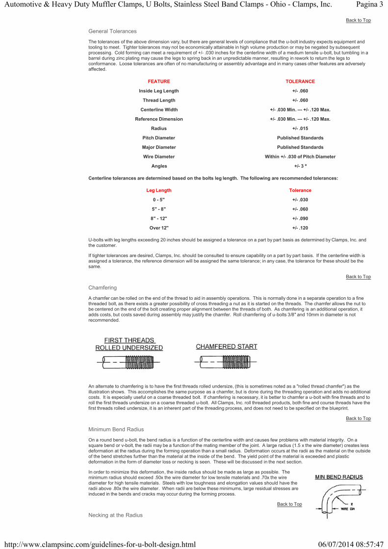
Chamfering
A chamfer can be rolled on the end of the thread to aid in assembly operations. This is normally done in a separate operation to a finethreaded bolt, as there exists a greater possibility of cross threading a nut as it is started on the threads. The chamfer allows the nut tobe centered on the end of the bolt creating proper alignment between the threads of both. As chamfering is an additional operation, itadds costs, but costs saved during assembly may justify the chamfer. Roll chamfering of u-bolts 3/8" and 10mm in diameter is notrecommended.
An alternate to chamfering is to have the first threads rolled undersize, (this is sometimes noted as a "rolled thread chamfer") as theillustration shows. This accomplishes the same purpose as a chamfer, but is done during the threading operation and adds no additionalcosts. It is especially useful on a coarse threaded bolt. If chamfering is necessary, it is better to chamfer a u-bolt with fine threads and toroll the first threads undersize on a coarse threaded u-bolt. All Clamps, Inc. roll threaded products, both fine and course threads have thefirst threads rolled undersize, it is an inherent part of the threading process, and does not need to be specified on the blueprint.
Back to Top
Minimum Bend Radius
On a round bend u-bolt, the bend radius is a function of the centerline width and causes few problems with material integrity. On asquare bend or v-bolt, the radii may be a function of the mating member of the joint. A large radius (1.5 x the wire diameter) creates lessdeformation at the radius during the forming operation than a small radius. Deformation occurs at the radii as the material on the outsideof the bend stretches further than the material at the inside of the bend. The yield point of the material is exceeded and plasticdeformation in the form of diameter loss or necking is seen. These will be discussed in the next section.
In order to minimize this deformation, the inside radius should be made as large as possible. Theminimum radius should exceed .50x the wire diameter for low tensile materials and .70x the wirediameter for high tensile materials. Steels with low toughness and elongation values should have theradii above .80x the wire diameter. When radii are below these minimums, large residual stresses areinduced in the bends and cracks may occur during the forming process.
Back to Top
Necking at the Radius
Pagina 4Automotive & Heavy Duty Muffler Clamps, U Bolts, Stainless Steel Band Clamps - Ohio - Clamps, Inc.
06/07/2014 08:57:47http://www.clampsinc.com/guidelines-for-u-bolt-design.html
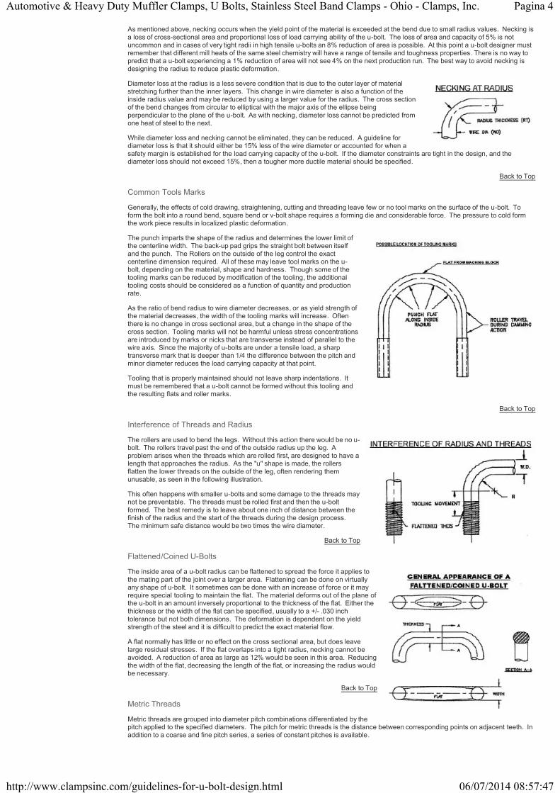
As mentioned above, necking occurs when the yield point of the material is exceeded at the bend due to small radius values. Necking isa loss of cross-sectional area and proportional loss of load carrying ability of the u-bolt. The loss of area and capacity of 5% is notuncommon and in cases of very tight radii in high tensile u-bolts an 8% reduction of area is possible. At this point a u-bolt designer mustremember that different mill heats of the same steel chemistry will have a range of tensile and toughness properties. There is no way topredict that a u-bolt experiencing a 1% reduction of area will not see 4% on the next production run. The best way to avoid necking isdesigning the radius to reduce plastic deformation.
Diameter loss at the radius is a less severe condition that is due to the outer layer of materialstretching further than the inner layers. This change in wire diameter is also a function of theinside radius value and may be reduced by using a larger value for the radius. The cross sectionof the bend changes from circular to elliptical with the major axis of the ellipse beingperpendicular to the plane of the u-bolt. As with necking, diameter loss cannot be predicted fromone heat of steel to the next.
While diameter loss and necking cannot be eliminated, they can be reduced. A guideline fordiameter loss is that it should either be 15% less of the wire diameter or accounted for when asafety margin is established for the load carrying capacity of the u-bolt. If the diameter constraints are tight in the design, and thediameter loss should not exceed 15%, then a tougher more ductile material should be specified.
Back to Top
Common Tools Marks
Generally, the effects of cold drawing, straightening, cutting and threading leave few or no tool marks on the surface of the u-bolt. Toform the bolt into a round bend, square bend or v-bolt shape requires a forming die and considerable force. The pressure to cold formthe work piece results in localized plastic deformation.
The punch imparts the shape of the radius and determines the lower limit ofthe centerline width. The back-up pad grips the straight bolt between itselfand the punch. The Rollers on the outside of the leg control the exactcenterline dimension required. All of these may leave tool marks on the u-bolt, depending on the material, shape and hardness. Though some of thetooling marks can be reduced by modification of the tooling, the additionaltooling costs should be considered as a function of quantity and productionrate.
As the ratio of bend radius to wire diameter decreases, or as yield strength ofthe material decreases, the width of the tooling marks will increase. Oftenthere is no change in cross sectional area, but a change in the shape of thecross section. Tooling marks will not be harmful unless stress concentrationsare introduced by marks or nicks that are transverse instead of parallel to thewire axis. Since the majority of u-bolts are under a tensile load, a sharptransverse mark that is deeper than 1/4 the difference between the pitch andminor diameter reduces the load carrying capacity at that point.
Tooling that is properly maintained should not leave sharp indentations. Itmust be remembered that a u-bolt cannot be formed without this tooling andthe resulting flats and roller marks.
Back to Top
Interference of Threads and Radius
The rollers are used to bend the legs. Without this action there would be no u-bolt. The rollers travel past the end of the outside radius up the leg. Aproblem arises when the threads which are rolled first, are designed to have alength that approaches the radius. As the "u" shape is made, the rollersflatten the lower threads on the outside of the leg, often rendering themunusable, as seen in the following illustration.
This often happens with smaller u-bolts and some damage to the threads maynot be preventable. The threads must be rolled first and then the u-boltformed. The best remedy is to leave about one inch of distance between thefinish of the radius and the start of the threads during the design process. The minimum safe distance would be two times the wire diameter.
Back to Top
Flattened/Coined U-Bolts
The inside area of a u-bolt radius can be flattened to spread the force it applies tothe mating part of the joint over a larger area. Flattening can be done on virtuallyany shape of u-bolt. It sometimes can be done with an increase of force or it mayrequire special tooling to maintain the flat. The material deforms out of the plane ofthe u-bolt in an amount inversely proportional to the thickness of the flat. Either thethickness or the width of the flat can be specified, usually to a +/- .030 inchtolerance but not both dimensions. The deformation is dependent on the yieldstrength of the steel and it is difficult to predict the exact material flow.
A flat normally has little or no effect on the cross sectional area, but does leavelarge residual stresses. If the flat overlaps into a tight radius, necking cannot beavoided. A reduction of area as large as 12% would be seen in this area. Reducingthe width of the flat, decreasing the length of the flat, or increasing the radius wouldbe necessary.
Back to Top
Metric Threads
Metric threads are grouped into diameter pitch combinations differentiated by thepitch applied to the specified diameters. The pitch for metric threads is the distance between corresponding points on adjacent teeth. Inaddition to a coarse and fine pitch series, a series of constant pitches is available.

Pagina 5Automotive & Heavy Duty Muffler Clamps, U Bolts, Stainless Steel Band Clamps - Ohio - Clamps, Inc.
06/07/2014 08:57:47http://www.clampsinc.com/guidelines-for-u-bolt-design.html
For each of the two main thread elements - pitch diameter and crest diameter - there are numerous tolerance grades. The number of thetolerance grade reflects the tolerance size. For example: Grade 4 tolerances are smaller than Grade 6 tolerances; Grade 8 tolerancesare larger than Grade 6 tolerances.
In each case, Grade 6 tolerances should be used for medium quality length of engagement applications. The tolerance grades belowGrade 6 are intended for applications involving fine quality and/or short lengths of engagement. Tolerance grades above Grade 6 areintended for coarse quality and/or long periods of engagement.
In addition to the tolerance grade, positional tolerance is required. The positional tolerance defines the maximum-material limits of thepitch and crest diameters of the external and internal threads and indicates their relationship to the basic profile.
In conformance with current coating (or plating) thickness requirements and the demand for ease of assembly, a series of tolerancepositions reflecting the application of varying amounts of allowance has been established:
For External Threads:
Tolerance position "e" (large allowance)Tolerance position "g" (small allowance)Tolerance position "h" (no allowance)
For Internal Threads:
Tolerance position "G" (small allowance)Tolerance position "H" (no allowance)
ISO metric screw threads are defined by nominal size (basic major diameter) and pitch, both expressed in millimeters. An "M" specifyingan ISO metric screw thread precedes the nominal size and as "X" separates the nominal size from the pitch. For coarse thread series,the pitch is shown only when the dimension for the length of the thread is required. When specifying the length of thread, an "X" is usedto separate the length of thread from, the rest of the designations. For external threads, the length of thread may be given as adimension on the drawing.
For example, a 10 mm diameter, 1.25 pitch, fine thread series is expressed as M10 X 1.25. A 10 mm diameter, 1.5 pitch, coarse threadseries is expressed as M10; the pitch need not be shown unless the length of the thread is required. If the latter thread was 25 mm longand this information was required on the drawing, the thread callout would be M10 X 1.5 X 25.
In addition to the basic designation, complete designation for an ISO metric screw thread includes a tolerance class identification. Adash separates the tolerance class identification from the basic designation and includes the symbol for the pitch diameter tolerancefollowed immediately by the symbol for crest diameter tolerance. Each of these symbols consists of a numeral indicating the gradetolerance followed by a letter indicating the tolerance position (a capital letter for internal threads and lowercase letter for externalthreads). Where the pitch and crest diameter symbols are identical, the symbol is necessary only once. Figure A illustrates the labelingof metric threads.
Figure B shows a comparison of metric threads and inch threads.
Back to Top
Thread Standards
There are several places to search for published standards relating to bolts and threaded items. Listed below are some of the majorsources with links to their web site.
Standards Organizations
ASTM - American Society For Testing and Materials
SAE - Society of Automotive Engineers

Pagina 6Automotive & Heavy Duty Muffler Clamps, U Bolts, Stainless Steel Band Clamps - Ohio - Clamps, Inc.
06/07/2014 08:57:47http://www.clampsinc.com/guidelines-for-u-bolt-design.html
Email: [email protected] www.clampsinc.com
Privacy Policy Site MapClamps, Inc. 5960 American Road East, Toledo, OH 43612
Phone: 800.837.0141 419.729.2141 Fax: 419.729.5776
IFI - Industrial Fasteners Institute
ISO - International Organization for Standardization
SCREW THREAD STANDARDS
ANSI B1.1 - Unified Screw ThreadsANSI B1.13M - Metric Screw Threads - M ProfileIFI - "Fastener Standards"IFI - "Metric Fastener Standards"
MATERIAL STANDARDS
ASTM Volume 15.08 - FastenersASTM A193/93M - Alloy-Steel and Stainless Steel Bolting Materials for High Temperature Service.ASTM A307 - Carbon Steel Bolts and Studs, 60,000 P.S.I Tensile strength.ASTM A325 - Structural Bolts, Steel, Heat Treated, 120/105 ksi Minimum Tensile Strength.SAE J429 - Mechanical and Material Requirements for Externally Threaded FastenersSAE J1199 - Mechanical and Material Requirements for Metric Externally Threaded Fasteners.
PLATING STANDARDS
ASTM A153 - Specification for Zinc Coating (Hot Dipped) on Iron and Steel Hardware.ASTM B633 - Electrodeposited Coatings of Zinc on Threaded Components.ASTM F871M - Electrodeposited Coatings of Threaded Components (Metric)ASTM A165 - Specifications for Electrodeposited Coatings of Cadmium on Steel.
Back to Top
Site created by ThomasNet Web Solutions and powered by Navigator Platform